Hanchett Entry Systems RF5X10 HES Hybrid Electric Strike User Manual users manual
Hanchett Entry Systems, Inc. HES Hybrid Electric Strike users manual
users manual

5015 B.U. Bowman Drive Buford, GA 30518 USA Voice: 770-831-8048 Fax: 770-831-8598
FCC Part 15.209
Transmitter Certification
Test Report
FCC ID: VC3-RF5X10
FCC Rule Part: 15.209
ACS Report Number: 07-0074-15C
Manufacturer: Hanchett Entry Systems, Inc.
Model(s): RF5010-IA, RF5010-EA, RF5210-IA, RF5210-EA
Installation Guide
Steel, Aluminum, Wood
Included
Cylindrical
RF5010: Accomodates up to 5/8" Latchbolt
RF5210: Accomodates up to 3/4" Latchbolt
Not Recommended for Outdoor use
32 F 150 F (0 C 65 C)
5 95%, Non-condensing
®RF5010 and RF5210
Installation Instructions
Cutout Template
Outswing Version
Product
Description
Dimensions
Orientation
Compatibility
Access Control Systems
Proximity Cards
Frequency
Indicators
Supervision
Integrated Electric Strike and Proximity Card Reader
See page 4
Non-handed, Reversible
Open Architecture
Interfaces with Wiegand Protocol Systems
Supports HID 26 39 Bit Formats
Supports HID 125 KHz Credentials
Red/Green LED and Buzzer
Door Position Switch and Latchbolt Monitor
Cable Detail
Reader Module
Distance to Host
Recommended Type
Electric Strike Module
Distance to Power
Recommended Type
500 ft. Max.
18 22 AWG (Dependent on Distance) Stranded and Shielded
See Page 3
See Page 3
Certifications
Compliance
Security
FCC Part 15 (USA and Canada)
UL 1034, Burglary-Resistant Listed
ANSI/BHMA 156.31, Grade 1
MEA New York City Accepted
Warranty
Lifetime Waranty
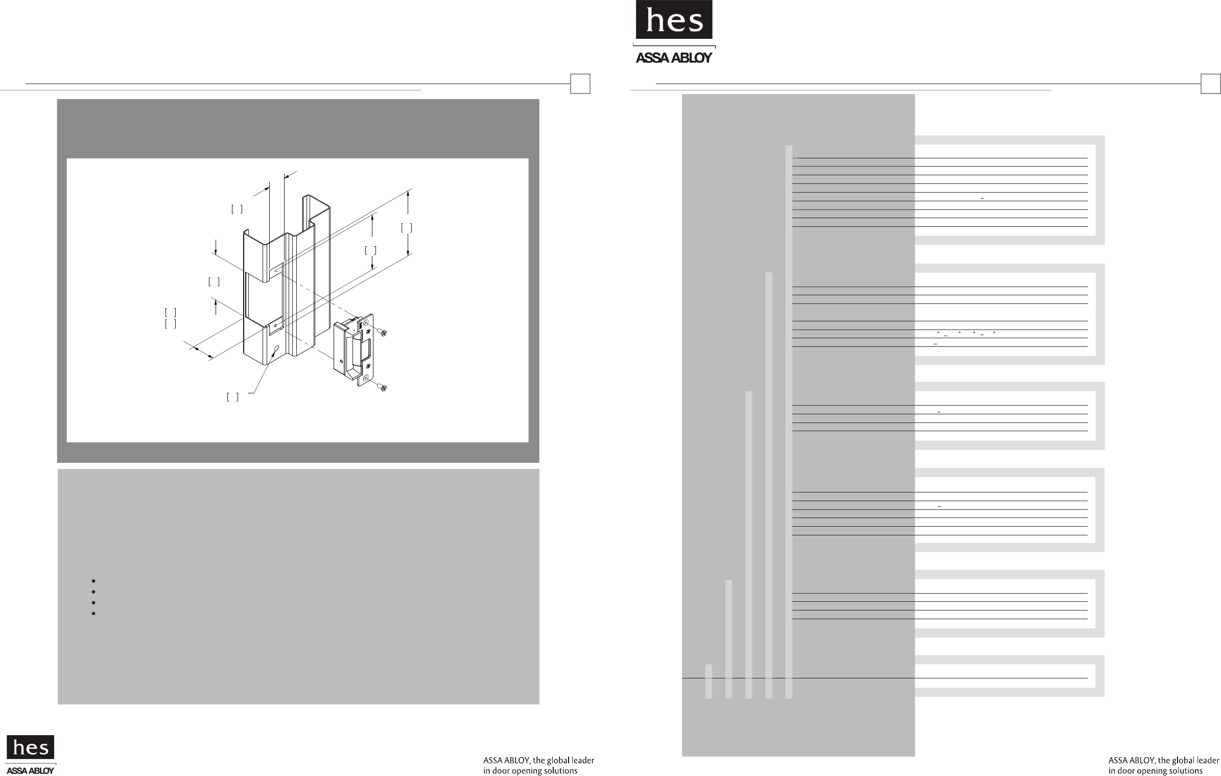
HYBRID ELECTRIC STRIKES: OUTSWING VERSIONRF5010 and RF52010: OUTSWING VERSION
HES, Inc.
22630 N. 17th Ave.
Phoenix, AZ 85027
800-626-7590
© 2007 HES, Inc.
0000000000.002 rev A
Door Position Switch Hybrid Electric Strike
®
Electrical
Reader Module
Operating Voltage 10 14VDC
Operating Current 125 mA Max. at 12VDC
Electric Strike Module 250mA @12VDC
Applications
Frames
Trim Enhancer
Locks
Latchbolts Released*
Environment
Temperature
Humidity
HID is a registered trademark of HID Corporation.
14
*Faceplate options accommodate
various keeper and latchbolt
actions. For more detail, contact
HES tech support
at 800-626-7590
3 -3/8"
86
43
46
1-1/4"
32
4 -7/8"
124
4 -1/8"
105
3/8"
10
RF5010: 11/16"
RF5210: 13/16"
1-1/4” x 4-7/8” Square Corner Faceplate
ANSI Metal Jamb Installation
RF5010 or RF5210 with 501 Faceplate
Warning: Changes or modification to this device not expressly approved by HES, Inc. could void the user’s authority to
operate the equipment.
NOTE: This equipment has been tested and found to comply with the limits for a class [B] digital device, pursuant to Part
15 of the FCC Rules. These limits are designed to provide reasonable protection against harmful interference in a
residential installation. This equipment generates, uses, and can radiate radio frequency energy and, if not installed and
used in accordance with the instructions, may cause harmful interference to radio communications. However, there is no
guarantee that interference will not occur in a particular installation. If this equipment does cause harmful interference
to radio or television reception, which can be determined by turning the equipment off and on, the user is encouraged to
try to correct the interference by one or more of the following measures:
Reorient or relocate the receiving antenna.
Increase the separation between the equipment and receiver.
Connect the equipment into an outlet on a circuit different from that to which the receiver is connected.
Consult the dealer or an experienced radio/TV technician for help
This class [B] digital apparatus meets all requirements of the Canadian interference Causing Equipment Regulations.
Operation is subject to the following two conditions: (1) this device may not cause harmful interference, and (2) this
device must accept any interference received, including interference that may cause undesired operation.
Cet appareillage numérique de la classe [B] répond à toutes les exigences de l’inerférencé canadienne causant des
réglements d’équipement. L’opération est sujette aux deux conditions suivantes: (1) ce dispositif peut ne pas causer
l’interférence nocive, et (2) ce dispositif doit accepter n’importe quelle interférence reçue, y compris l’interférence qui
peut causer l’opération peu désirée.
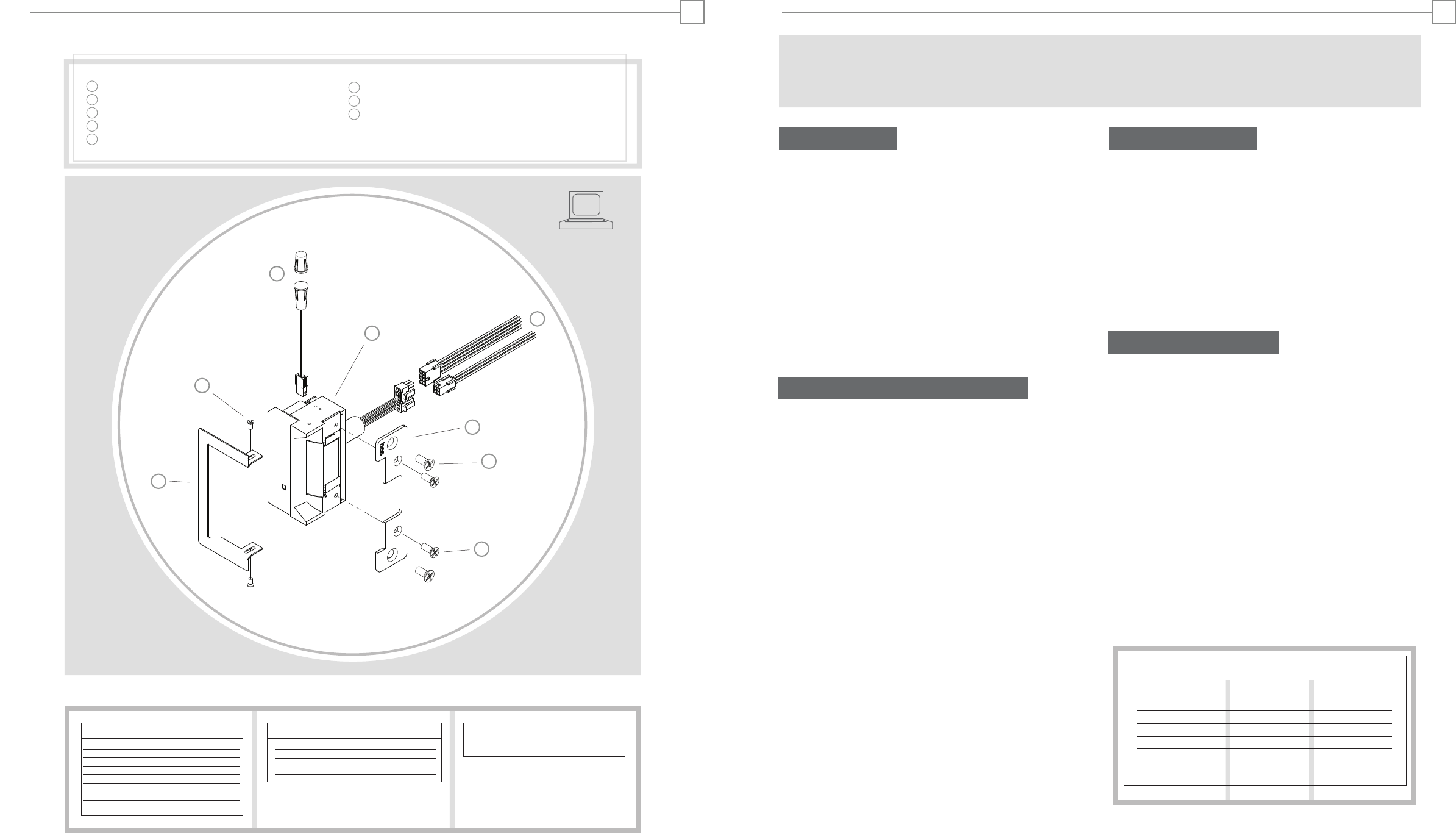
Product Components
RF5010 and RF5210: OUTSWING VERSION RF5010 and RF5210: OUTSWING VERSION
Hybrid Electric Strike
Pigtail Connectors (8 pin and 4 pin)
Faceplate (sold separately)
#12-24 Mounting Screws (included with faceplate)
#8-32 Faceplate Screws (included with faceplate)
Trim Enhancer (optional)
Trim Enhancer Screws
Door Position Switch, Press-Fit Magnet
and 10” Connector Cable (2 pin)
1
2
3
4
5
6
7
8
Access Control System
Control Panel and Power Supply
(By others)
8 Pin Connector (Reader Module)
Red (+) Board Power 10 - 14 VDC
Black ( ) Board Power
Green Data 0
White Data 1
Yellow LED/Buzzer
Blue Not Used
Orange Not Used
Brown Not Used
Wire Gauge Diagram
Max. One-way Distance Voltage Drop/100’ Recommended AWG
800’
500’
300’
200’
120’
100’ or less
4 Pin Connector (Strike Module)
Gray (+) Strike Power 12 VDC
Violet ( ) Strike Power
Tan Common
Pink Door Closed and Latch Engaged
2 Pin Connector (Door Position Switch)
Wire plugs into Hybrid Electric Strike
Installation Directions
CAUTION! Before connecting any device at the installation site, verify that there is 12VDC input voltage using a multimeter.
Many power supplies and low voltage transformers operate at higher levels than listed. Any input voltage outside the electrical
specifications outlined on page 1 may cause severe damage to the unit and will void the warranty.
1. Prepare door jamb for hybrid electric strike per the appro-
priate template detail (see page 4). Be sure to allow enough
room behind the strike in the cutout to avoid pinching any
wires.
2. Drill a 3/8” hole for the door position switch per the appro-
priate template detail (see page 4). Note that the door position
switch may be positioned as desired, within limits of its 10”
connector. Next, drill a matching 3/8” hole in the door and
install the press-fit magnet so that it comes into contact with
the door position switch.
3. Install mounting tabs (sold separately as P/N 152) when
applicable, using #10-32 screws.
4. Check that the wires running from the host control panel
and/or power supply are correct for the components and
distance (see Wiring Diagram on page 2 and Wire Gauge
Diagram below). Connect the two pigtails provided (8 pin and
4 pin) to these wires. Note that a linear power supply is
recommended.
5. Connect and mount the door position switch, routing its 10”
cable from the door position switch to the hybrid electric
strike.
6. Plug the loose end of the door position switch cable into the
2 pin connector on the bottom of the hybrid electric strike.
7. Connect the wire bundle on the side of the hybrid electric
strike to the pigtails/wire back to the host control panel. Check
any pertinent information from the access control system
installation guide or manual.
Prepare Frame
8. Attach the faceplate to the hybrid electric strike, using the
#8-32 screws provided.
9. Install the trim enhancer on the hybrid electric strike (if
needed to cover any extra space).
10. Install the hybrid electric strike in jamb cutout, using
#12-24 screws provided (or wood screws where necessary).
11. Tighten the #10-32 screws holding the mounting tabs
(when applicable).
Finishing Installing
12. When power is supplied to the hybrid electric strike, the
LED should flash green three times, while the beeper simulta-
neously beeps. The LED should then turn red. This sequence
indicates that the micro-controller is operating properly.
13. Present a Proximity ID card to the reader/antenna. The LED
will turn green, while the beeper beeps once. This indicates
that the card was read successfully.
14. Simultaneously, the keeper should click open. This
indicates that communication between the host and the
hybrid electric strike is operational.
15. For further testing of communication with the host, consult
the manual for the host control panel or the site’s system
administrator.
Testing and Operation
Connect Components and Wiring
12VDC @ 250 mA
0.16
0.25
0.40
0.64
1.01
1.6
12 Gauge
14 Gauge
16 Gauge
18 Gauge
20 Gauge
22 Gauge
Wiring Diagram
23
- -
1
2
3
4
5
6
8
7
®RF5010 and RF5210
1-1/4” x 4-7/8” Square Corner Faceplate
ANSI Metal Jamb Installation
RF5000 or RF5200 with 501 Faceplate
1-1/4” x 4-7/8” Square Corner Faceplate
ANSI Metal Jamb Installation
RF5000 or RF5200 with 501 Faceplate
Installation Instructions
Cutout Template
Product
Applications
Electrical
Cable detail
Certifications
Warranty
Description
Dimensions
Orientation
Compatibility
Access Control Systems
Proximity Cards
Frequency
Indicators
Supervision
Electric Strike and Proximity Card Reader with
Antenna Module Mounted Separately in Frame
See page 4
Non handed, Reversible
Open Architecture
Interfaces with Wiegand Protocol Systems
Supports HID 26 39 Bit Formats
Supports HID 125 KHz Credentials
Red/Green LED and Buzzer
Door Position Switch and Latchbolt Monitor
Frames
Trim Enhancer
Locks
Latchbolts Released*
Environment
Temperature
Humidity
Steel, Aluminum, Wood
Included
Cylindrical
RF5010: Accomodates up to 5/8" Latchbolt
RF5210: Accomodates up to 3/4" Latchbolt
Suitable for Exterior Doors
32 F 150 F (0 C 65 C)
5 95%, Non-condensing
Reader Module
Distance to Host
Recommended Type
Electric Strike Module
Distance to Power
Recommended Type
500 ft. Max.
18 22 AWG (Dependent on Distance) Stranded and Shielded
See Page 3
See Page 3
Compliance
Security FCC Part 15 (USA and Canada)
UL 1034, Burglary-Resistant Listed
ANSI/BHMA 156.31, Grade 1
MEA New York City Accepted
Lifetime Waranty
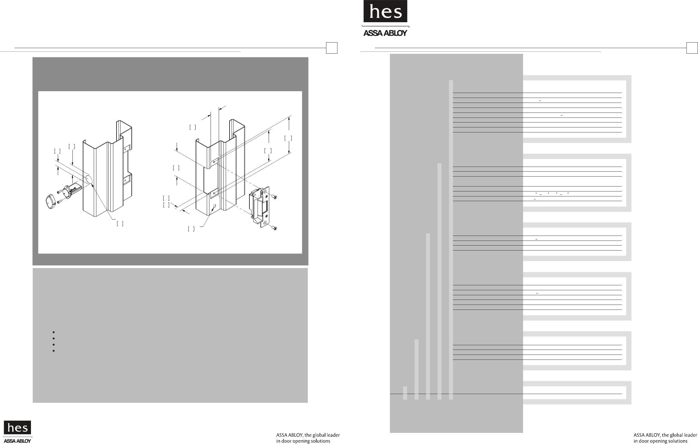
Inswing Version
HYBRID ELECTRIC STRIKES: INSWING VERSIONHYBRID ELECTRIC STRIKES: INSWING VERSION
HES, Inc.
22630 N. 17th Ave.
Phoenix, AZ 85027
800-626-7590
3 -3/8"
86
RF5010: 11/16"
RF5210: 13/16" 21
1-1/4"
32
4- 7/8"
124
4-1/8"
105
3/8"
10
1"
1-5/16"
33
5/8"
17
25
17
© 2007 HES, Inc.
0000000000.001 rev A
Reader/Antenna Door Position Switch Hybrid Electric Strike
®
Reader Module
Operating Voltage 10 14VDC
Operating Current 125 mA Max. at 12VDC
Electric Strike Module 250mA @12VDC
HID is a registered trademark of HID Corporation.
14
*Faceplate options accommodate
various keeper and latchbolt
actions. For more detail, contact
HES tech support
at 800-626-7590
1-1/4” x 4-7/8” Square Corner Faceplate
ANSI Metal Jamb Installation
RF5010 or RF5210 with 501 Faceplate
Warning: Changes or modification to this device not expressly approved by HES, Inc. could void the user’s authority to
operate the equipment.
NOTE: This equipment has been tested and found to comply with the limits for a class [B] digital device, pursuant to Part
15 of the FCC Rules. These limits are designed to provide reasonable protection against harmful interference in a
residential installation. This equipment generates, uses, and can radiate radio frequency energy and, if not installed and
used in accordance with the instructions, may cause harmful interference to radio communications. However, there is no
guarantee that interference will not occur in a particular installation. If this equipment does cause harmful interference
to radio or television reception, which can be determined by turning the equipment off and on, the user is encouraged to
try to correct the interference by one or more of the following measures:
Reorient or relocate the receiving antenna.
Increase the separation between the equipment and receiver.
Connect the equipment into an outlet on a circuit different from that to which the receiver is connected.
Consult the dealer or an experienced radio/TV technician for help
This class [B] digital apparatus meets all requirements of the Canadian interference Causing Equipment Regulations.
Operation is subject to the following two conditions: (1) this device may not cause harmful interference, and (2) this
device must accept any interference received, including interference that may cause undesired operation.
Cet appareillage numérique de la classe [B] répond à toutes les exigences de l’inerférencé canadienne causant des
réglements d’équipement. L’opération est sujette aux deux conditions suivantes: (1) ce dispositif peut ne pas causer
l’interférence nocive, et (2) ce dispositif doit accepter n’importe quelle interférence reçue, y compris l’interférence qui
peut causer l’opération peu désirée.
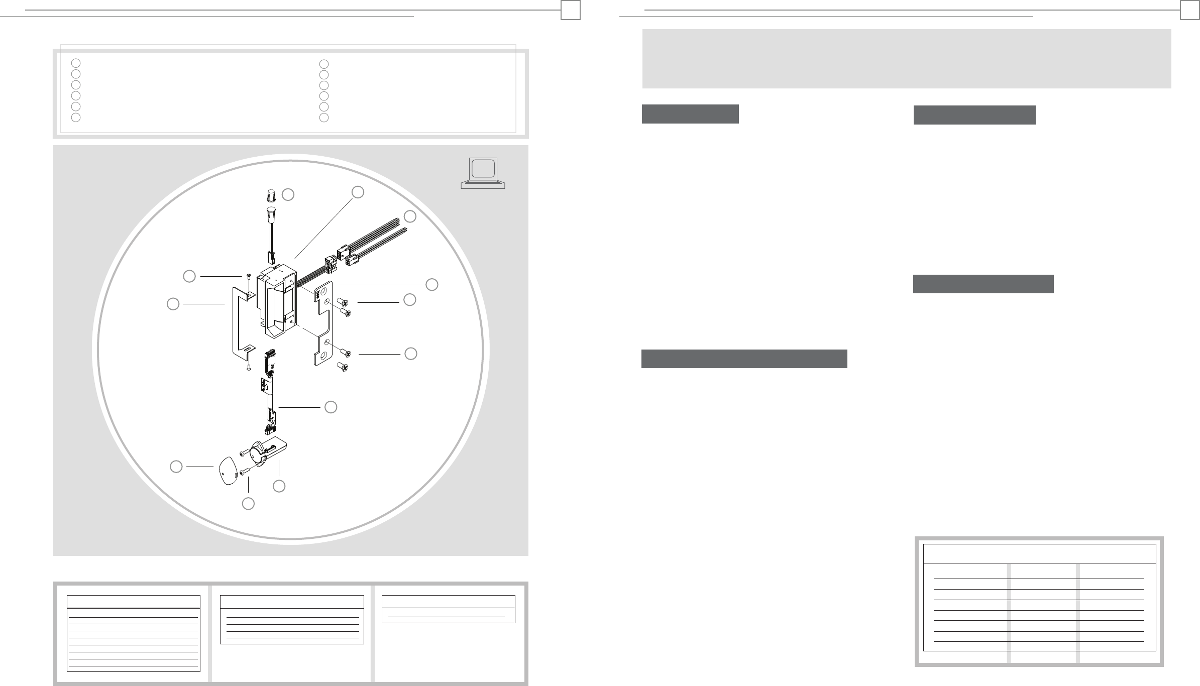
Product Components
Environment
Hybrid Electric Strike
Pigtail Connectors (8 pin and 4 pin)
Faceplate (sold separately)
#12-24 Mounting Screws (included with faceplate)
#8-32 Faceplate Screws (included with faceplate)
24” Cable (connecting reader/antenna and strike)
Reader/Antenna Body
#6-32 Reader/Antenna Screws
Reader/Antenna Cover
Trim Enhancer (optional)
Trim Enhancer Screws
Door Position Switch, Press-Fit Magnet
and 10” Connector Cable (2 Pin)
RF5010 and RF5210: INSWING VERSION RF5010 and RF5210: INSWING VERSION
12
10
11
1
2
3
4
5
6
7
8
9
1
2
3
4
5
6
7
8
9
11
10
12
Access Control System
Control Panel and Power Supply
(By others)
8 Pin Connector (Reader Module)
Red (+) Board Power 10 -14 VDC
Black ( ) Board Power
Green Data 0
White Data 1
Yellow LED/Buzzer
Blue Not Used
Orange Not Used
Brown Not Used
Wire Gauge Diagram
Max. One-way Distance Voltage Drop/100’ Recommended AWG
800’
500’
300’
200’
120’
100’ or less
4 Pin Connector (Strike Module)
Gray (+) Strike Power
Violet ( ) Strike Power 12 VDC
Tan Common
Pink Door Closed and Latch Engaged
2 Pin Connector (Door Position Switch)
Wire plugs into Hybrid Electric Strike
Installation Directions
CAUTION! Before connecting any device at the installation site, verify that there is 12VDC input voltage using a multimeter.
Many power supplies and low voltage transformers operate at higher levels than listed. Any input voltage outside the electrical
specifications outlined on page 1 may cause severe damage to the unit and will void the warranty.
1. Prepare door jamb for hybrid electric strike per the appro-
priate template detail (see page 4). Be sure to allow enough
room behind the strike in the cutout to avoid pinching any
wires.
2. Drill a 1” diameter hole for reader/antenna per the appropri-
ate template detail (see page 4). Note that the reader/antenna
may be positioned as desired, within limits of the 24”cable.
3. Drill a 3/8” hole for the door position switch per the appro-
priate template detail (see page 4). Note that the door position
switch may be positioned as desired, within limits of its 10”
connector. Next, drill a matching 3/8” hole in the door and
install the press-fit magnet so that it comes into contact with
the door position switch.
4. Install mounting tabs (sold separately as P/N 152) when
applicable, using #10-32 screws.
5. Check that the wires running from the host control panel
and/or power supply are correct for the components and
distance (see Wiring Diagram on page 2 and Wire Gauge
Diagram below). Connect the two pigtails provided (8 pin and
4 pin) to these wires. Note that a linear power supply is
recommended.
6. Connect and mount the door position switch, routing its 10”
cable from the door position switch to the hybrid electric
strike.
7. Plug the loose end of the door position switch cable into the
2 pin connector on the bottom of the hybrid electric strike.
8. Connect the 24” cable to the reader/antenna (check labels to
insure that you connect the correct end). Then, install the
reader/antenna in the frame, using the #6-32 screws provided.
Snap on the reader/antenna cover and pull the 24”cable
through to the hybrid electric strike.
9. Plug the loose end of the 24” cable into the 7 pin connector
on the side of the hybrid electric strike.
10. Connect the wire bundle on the top of the hybrid electric
strike to the pigtails/wire back to the host control panel. Check
any pertinent information from the access control system
installation guide or manual.
Prepare Frame
11. Attach the faceplate to the hybrid electric strike, using the
#8-32 screws provided.
12. Install the trim enhancer on the hybrid electric strike (if
needed to cover any extra space).
13. Install the hybrid electric strike unit in jamb cutout, using
#12-24 screws provided (or wood screws where necessary).
14. Tighten the #10-32 screws holding the mounting tabs
(when applicable).
Finishing Installing
15. When power is supplied to the hybrid electric strike, the
LED should flash green three times, while the beeper simulta-
neously beeps. The LED should then turn red. This sequence
indicates that the micro-controller is operating properly.
16. Present a Proximity ID card to the reader/antenna. The LED
will turn green, while the beeper beeps once. This indicates
that the card was read successfully.
17. Simultaneously, the keeper should click open. This
indicates that communication between the host and the
hybrid electric strike is operational.
18. For further testing of communication with the host, consult
the manual for the host control panel or the site’s system
administrator.
Testing and Operation
Connect Components and Wiring
12VDC @ 250 mA
0.16
0.25
0.40
0.64
1.01
1.6
12 Gauge
14 Gauge
16 Gauge
18 Gauge
20 Gauge
22 Gauge
Wiring Diagram
23
- -