Hanchett Entry Systems XX20 HES Hybrid Electric Strike iCLASS User Manual ic5020 ic5220 1 8
Hanchett Entry Systems, Inc. HES Hybrid Electric Strike iCLASS ic5020 ic5220 1 8
Installation Instructions
IC5020 and IC5220
Installation Instructions
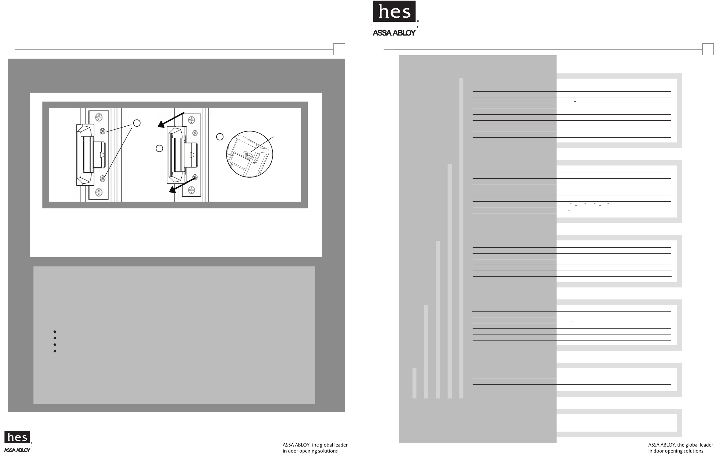
Horizontal Adjustability
Product
Applications
Electrical
Cable detail
Certifications
Warranty
Description
Dimensions
Orientation
Compatibility
Access Control Systems
Proximity Cards
Frequency
Indicators
Supervision
Electric Strike and Proximity Card Reader with
Antenna Module Mounted Separately in Frame
See pages 4-6
Non handed
Open Architecture
Interfaces with Wiegand Protocol Systems
Supports HID 26, 32, 34, 37, 40 & 56 Bit Formats
Supports HID 13.56 MHz Credentials
Red/Green LED and Buzzer
Door Position Switch and Latchbolt Monitor
Frames
Trim Enhancer
Locks
Latchbolts Released*
Environment
Temperature
Humidity
Steel, Aluminum
Included
Cylindrical
IC5020: Accomodates up to 5/8" Latchbolt
IC5220: Accomodates up to 3/4" Latchbolt
Suitable for Exterior Doors
32 F 150 F (0 C 65 C)
5 95%, Non-condensing
Reader Module
Distance to Host
Recommended Type
Electric Strike Module
Distance to Power
Recommended Type
500 ft. Max.
18 22 AWG (Dependent on Distance) Stranded and Shielded
See Page 3
See Page 3
Compliance
Security
FCC Part 15/IC Class B
ANSI/BHMA 156.31, Grade 1
Lifetime Waranty against defects
in materials and workmanship
IC5020 and IC5220: EXTERNAL ANTENNAIC5220 (ONLY):
HES, Inc.
22630 N. 17th Ave.
Phoenix, AZ 85027
800-626-7590
©2010 HES, Inc.
3065006.001 rev A1
Reader Module
Operating Voltage 12VDC +/- 20%
Operating Current
Electric Strike Module
Operating Voltage 12-24VDC +/- 10%
Operating Current 240 mA max. @ 12VDC 120mA max. @ 24VDC
HID is a registered trademark of HID Corporation.
18
*Faceplate options accommodate
various keeper and latchbolt
actions. For more detail, contact
HES tech support
at 800-626-7590
Warning:Changes or modification to this device not expressly approved by HES, Inc., could void the user’s authority
to operate the equipment.
NOTE: This equipment has been tested and found to comply with the limits for a class [B] digital device, pursuant to Part
15 of the FCC Rules. These limits are designed to provide reasonable protection against harmful interference in a
residential installation. This equipment generates, uses, and can radiate radio frequency energy and, if not installed and
used in accordance with the instructions, may cause harmful interference to radio communications. However, there is no
guarantee that interference will not occur in a particular installation. If this equipment does cause harmful interference
to radio or television reception, which can be determined by turning the equipment off and on, the user is encouraged to
try to correct the interference by one or more of the following measures:
Reorient or relocate the receiving antenna.
Increase the separation between the equipment and receiver.
Connect the equipment into an outlet on a circuit different from that to which the receiver is connected.
Consult the dealer or an experienced radio/TV technician for help
This class [B] digital apparatus meets all requirements of the Canadian Interference Causing Equipment Regulations.
Operation is subject to the following two conditions: (1) this device may not cause harmful interference, and (2) this
device must accept any interference received, including interference that may cause undesired operation.
Cet appareillage numérique de la classe [B] répond à toutes les exigences de l’inerférencé canadienne causant des
réglements d’équipement. L’opération est sujette aux deux conditions suivantes: (1) ce dispositif peut ne pas causer
l’interférence nocive, et (2) ce dispositif doit accepter n’importe quelle interférence reçue, y compris l’interférence qui
peut causer l’opération peu désirée.
125 mA Max. @ 12VDC
a
b
c
a. If you need to make horizontal adjustments, begin by slowly turning the horizontal adjustment screws on the faceplate.
Do not remove the screws or rotate them more than 3 full turns
b. Adjust the unit in the frame.
c. To finish, securely tighten the screws. this allows the K-nut’s teeth to dig into the unit’s housing to prevent slippage during use.
K-NUT
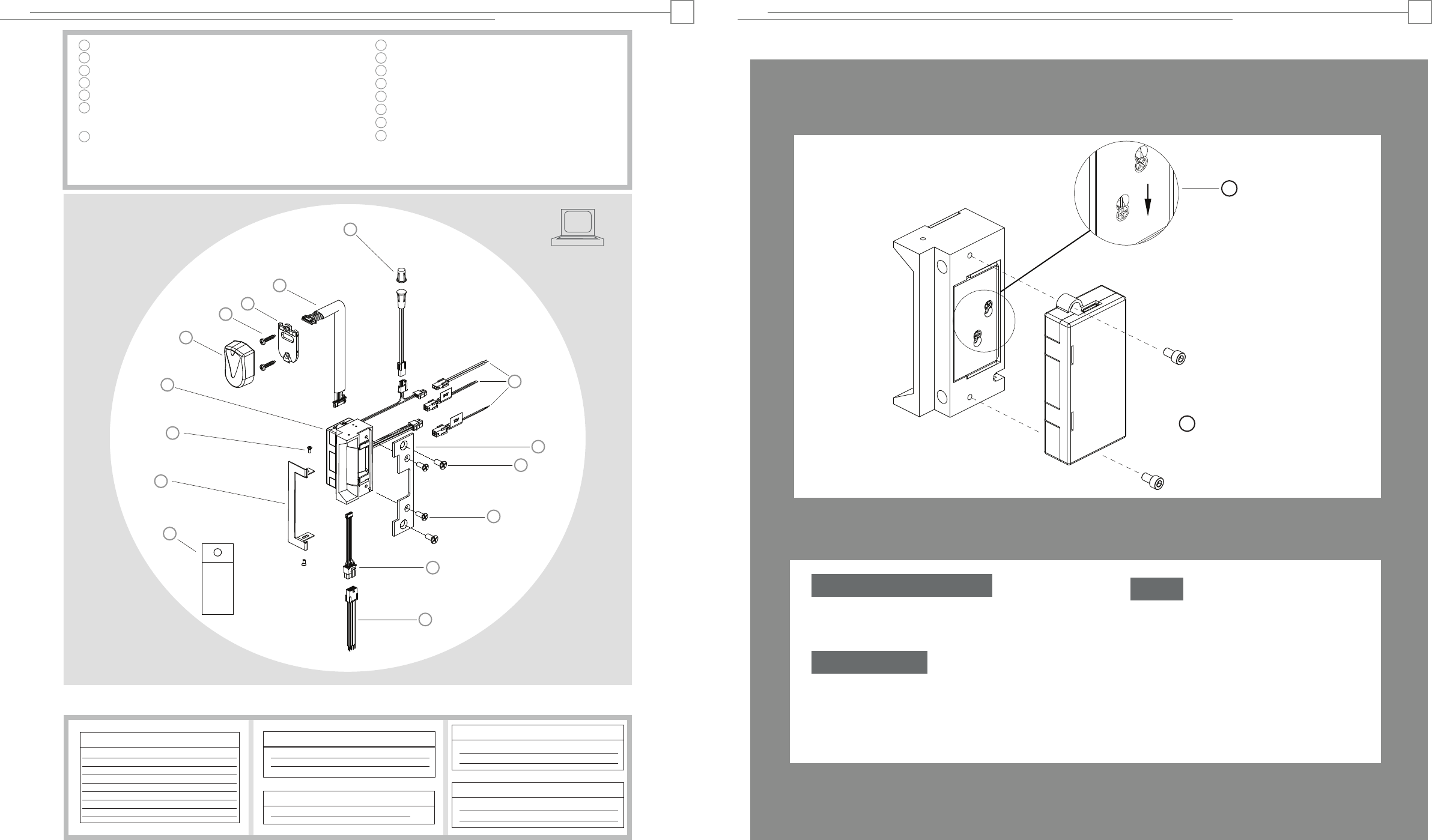
Hybrid Electric Strike
Reader/Antenna Body
#6-32 Reader/Antenna Screws
Reader/Antenna Mounting Plate
24” Cable (connecting reader/antenna and strike)
Door Position Switch, Press-Fit Magnet
and 10” Connector Cable (2 pin)
Product Components
Pigtail Connectors
2 pin-DPS & LBM
4 pin-12V Strike Power
4 pin-24V Strike Power
Faceplate (sold seperately)
#12-24 Mounting Screws (included with faceplate)
#8-32 Faceplate Screws (included with faceplate)
Prox & Data Connector (connects to strike)
Prox & Data Pigtail
Dielectric Grease (for humid applications)
IC5020 and IC5220: EXTERNAL ANTENNA
1
2
3
4
5
6
7
8
9
11
10
12
13
Access Control System
Control Panel and Power Supply
(By others)
8 Pin Connector (Reader Module)
Red (+) Board Power
Black ( ) Board Power
Green Data 0
White Data 1
Yellow LED/Buzzer
Blue Not Used
Orange Not Used
Brown Not Used
2 Pin Connector (Door Position Switch)
Wire plugs into Hybrid Electric Strike
Wiring Diagram
2
Fail Safe Conversion
IC5020 and IC5220: EXTERNAL ANTENNA 7
-
2 pin Connector (Strike Module)
Tan Common
Pink Door Closed and Latch Engaged
Dielectric
Grease
a. In order to change the mode of operation from fail secure
(standard) to fail safe, first detach the reader module by removing
the two screws on the back of the hybrid electric strike.
Remove Reader Module
b. Loosen the two #2-56 screws located on the back of the
strike module, as shown above, but do not remove them.
c. Move screws from the top of the hole to fail safe position.
d. Tighten screws.
Convert Mode
e. Replace the reader module and tighten the two
screws to hold it in place.
Finish
cFail Safe
-or-
1
2
3
5
6
7
8
9
10
12
11
14
15
4
13
a
Trim Enhancer
14
Trim Enhancer Screws
15
4 Pin Connector (12V Strike Power)
Red (+) Strike Power
Black (−) Strike Power
4 Pin Connector (24V Strike Power)
Violet (+) Strike Power
Black (−) Strike Power
Cutout Template
IC5020 and IC5220: EXTERNAL ANTENNA 6
10
3/8”
17
5/8”
19
3/4”
1 - 9/16” 40
86
3 - 3/8”
35
1 - 3/8”
1/8”
254
10”
33
1 - 5/16”
17
IC5020: 11/16”
Reader/Antenna Hybrid Electric Strike
4
R- 5/32”
21
IC5220: 13/16”
3
IC5020 and IC5220: EXTERNAL ANTENNA
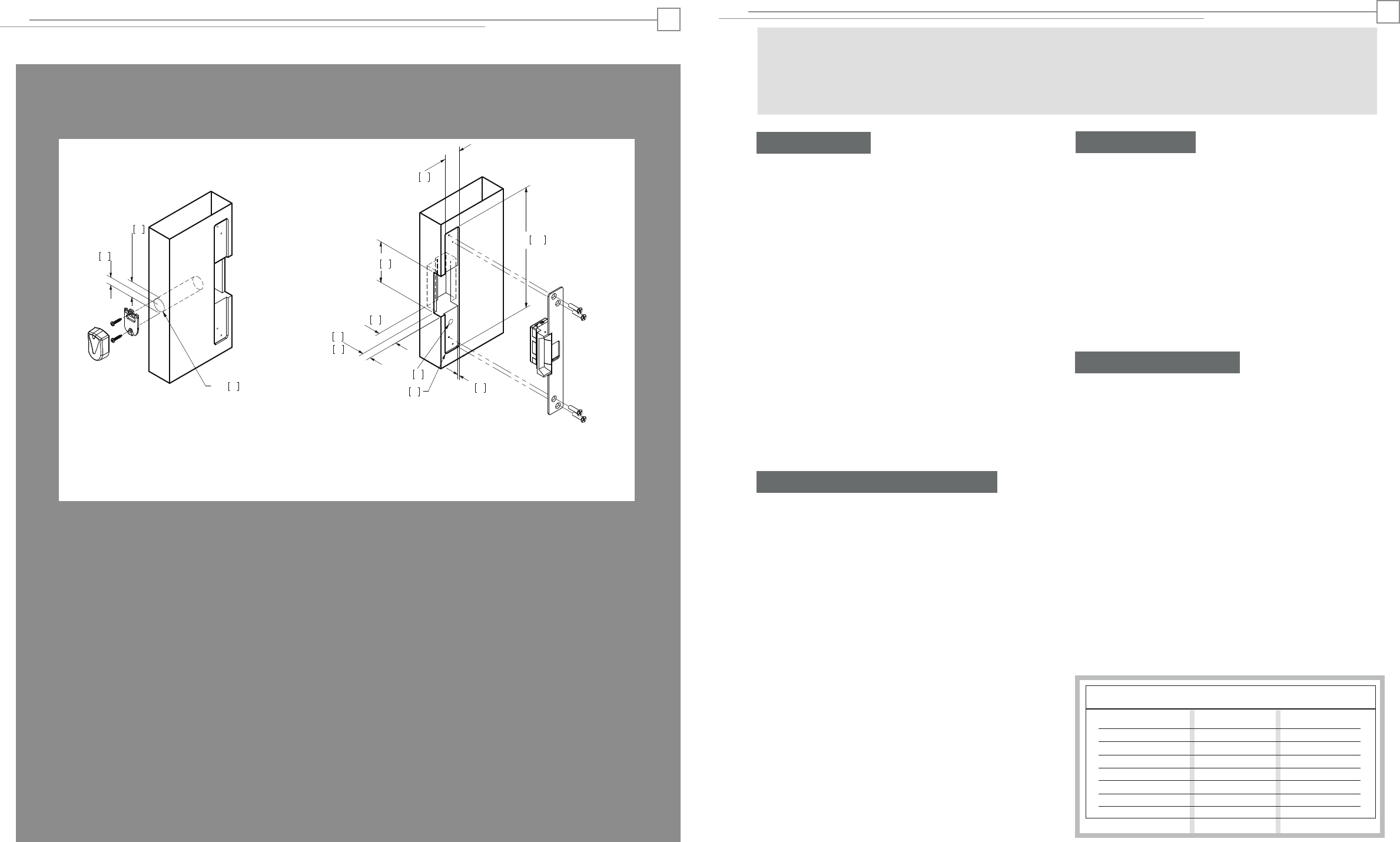
Installation Directions
1. Prepare door jamb for hybrid electric strike per the appropriate
template detail (see pages 4-6). Be sure to allow enough room
behind the strike in the cutout to avoid pinching any wires.
2. Drill a 1” diameter hole for reader/antenna per the appropriate
template detail (see pages 4-6). Note that the reader/antenna may
be positioned as desired, within limits of the 24”cable. If necessary,
drill a channel from the reader/antenna to the hybrid electric strike
to accomodate the 24“ cable.
3. Drill a 3/8” hole for the door position switch per the appropriate
template detail (see pages 4-6). Note that the door position switch
may be positioned as desired, within limits of its 10” connector. If
necessary, drill a channel from the door position switch to hybrid
electric strike to accomodate the 10“ cable. Next, drill a matching
3/8” hole in the door and install the press-fit magnet so that it will
contact with the door position switch.
4. If applicable (e.g. aluminum frames), install mounting tabs (sold
separately as P/N 152) using #10-32 screws.
5. Verify that the strike is in the correct mode of operation. This
unit ships in fail secure mode. If you need to convert to fail safe, see
page 7.
10. Plug the loose end of the 24” cable into the connector on the
side of the hybrid electric strike.
Prepare Frame
11. Attach the faceplate to the hybrid electric strike, using the
#8-32 screws provided.
12. Install the trim enhancer on the hybrid electric strike (if
needed to cover any extra space).
13. Install the hybrid electric strike unit in jamb cutout, using
#12-24 screws provided.
14. If needed, see page 8 to make horizontal adjustments in
frame (IC5220 only).
15. If applicable, tighten the #10-32 screws holding the
mounting tabs.
Finish Installing
16. When power is supplied to the hybrid electric strike, the LED
will flash green three times, while the beeper simultaneously
beeps. The LED will then turn red. This sequence indicates that the
micro-controller is operating properly.
17. Present a Proximity ID card to the reader/antenna. The LED will
turn green, while the beeper beeps once. This indicates that the
card was read successfully.
18. Simultaneously, the keeper will click open. This indicates that
communication between the host and the hybrid electric strike is
operational.
19. For further testing of communication with the host, consult the
manual for the control panel or the site’s system administrator.
Testing and Operation
Connect Components and Wiring
Wire Gauge Diagram
Max. One-way Distance Voltage Drop/100’ Recommended AWG
800’
500’
300’
200’
120’
100’ or less
12VDC @ 240 mA
0.15
0.24
0.38
0.61
0.97
1.53
12 Gauge
14 Gauge
16 Gauge
18 Gauge
20 Gauge
22 Gauge
3
Remove additional material as
needed to provide clearance for
hybrid electric strike and wires
6. Check that the wires running from the host control panel are
adequate wire gauge for the components and distance (see Wire
Gauge Diagram below). Connect the wire leads of the three pigtails
provided to the host control panel wiring based on the wiring
diagram on page 2 and the appropriate termination at the host
control panel.
7. Mount the door position switch (DPS) into the frame. Route the
10” cable back to the electric strike and connect it to the 2 pin
connector coming out of the hybrid electric strike. It does not
matter which 2 pin connector is used. Note: the LBM & DPS are
wired in series--a ‘closed’ electrical circuit depicts a closed door
and extended latchbolt into the hybrid electric strike.
8. Attach the 8, 4 and 2 pin connectors at the hybrid electric strike
to the equivalent pigtail connectors routed from the host control
panel. Apply grease to the pigtail electrical terminals if used in a
humid environment
CAUTION! Before connecting any device at the installation site, verify input voltage using a multimeter. Many power supplies
and low voltage transformers operate at higher levels than listed. Any input voltage outside the electrical specifications
outlined on page 1 may cause severe damage to the unit and will void the warranty. This product contains electrostatic sensitive
components. We recommend proper grounding techniques be observed during installation.
IC5020 or IC5220 with 504 Faceplate
1-3/8” x 10” Radius Corner Faceplate
Aluminum Jamb Installations
9. Secure the Reader/Antenna Mounting Plate to the frame
using the #6-32 screws provided. Connect the 24” cable to
the Reader/Antenna, snap the Reader/Antenna to the
Reader/Antenna Mounting Plate and pull the 24” cable
through to the hybrid electric strike.
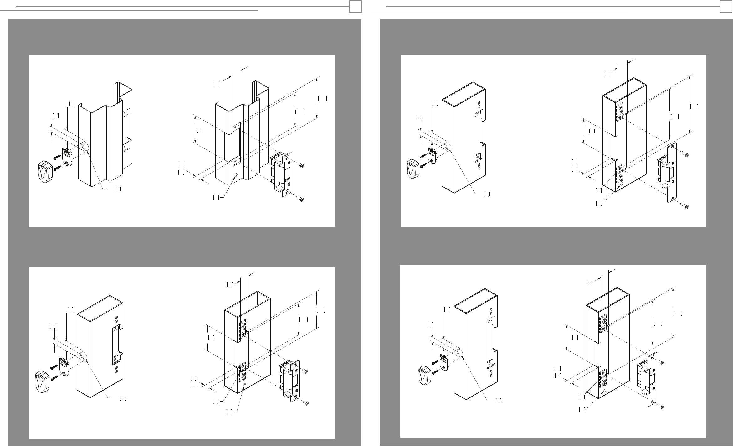
1-1/4” x 4-7/8” Square Corner Faceplate
ANSI Metal Jamb Installations
IC5020 or IC5220 with 501 Faceplate
1-1/4” x 4-7/8” Radius Corner Faceplate
Aluminum Jamb Installations
IC5020 or IC5220 with 501-A Faceplate
Cutout Template
IC5020 and IC5220: EXTERNAL ANTENNA
10
86
32
33
17
3-3/8”
1-1/4”
3/8”
1-5/16”
5/8”
124
4 -7/8”
4 -1/8” 105
17
11/16”
IC5020:
21
13/16”
IC5220:
Reader/Antenna Hybrid Electric Strike
Reader/Antenna Hybrid Electric Strike
33
1 - 5/16”
4 - 1/8” 105
124
4 - 7/8”
3/8” 10
R- 5/32” 4
17
5/8”
3 - 3/8” 86
32
1 - 1/4”
17
IC5020 :11/16”
21
IC5220: 13/16”
4
1-7/16” x 7-15/16” Radius Corner Faceplate
Aluminum Jamb Installations
IC5020 or IC5220 with 502 Faceplate
1-1/4” x 6-7/8” Radius Corner Faceplate
Aluminum Jamb Installations
IC5010 or IC5220 with 503 Faceplate
Cutout Template
IC5020 and IC5220: EXTERNAL ANTENNA
Reader/Antenna Hybrid Electric Strike
Reader/Antenna Hybrid Electric Strike
175
6 - 7/8”
3/8”
3 - 3/8”
6 -1/8” 156
R- 5/32”
86
21
11/16”
IC5020:
IC5220: 13/16”
5
32
1 - 1/4”
33
1 - 5/16"
17
5/8"
4
10
17
Remove additional material as
needed to provide clearance for
hybrid electric strike and wires
19
3/4”
19
3/4”
19
3/4”
202
7 - 15/16”
3/8”
3 - 3/8”
7 -7/16” 189
R- 5/32”
86
21
11/16”
IC5020:
IC5220: 13/16”
37
1 - 7/16”
33
1 - 5/16"
17
5/8"
4
10
17
19
3/4”