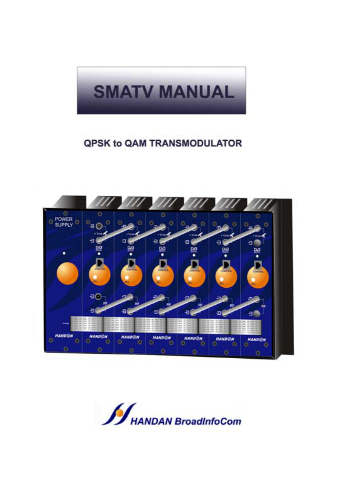
Handan BroadInfoCom HST-2000SC Digital Satellite Receiver User Manual users manual
Handan BroadInfoCom Digital Satellite Receiver users manual
users manual

1
CONTENTS
1. Safety Instructions 2
2. Specifications 6
3. Assembling Instructions 8
4. Descriptions 11
5. Installation 16
6. Channel & Frequency Table 19
•Read Instructions - All the safety and operating instructions should be read before the product is
operated.
•Retain Instructions - The safety and operating instructions should be retained for future reference.
•Heed Warnings - All warning on the product in the operating instructions should be adhered to.
•Follow Instructions - All operating and use instructions should be followed.
•Cleaning - Unplug this product from the wall outlet before cleaning. Do not use liquid cleaners or
aerosol cleaners. Use a damp cloth for cleaning.
•Attachments - Do not use attachments not recommended by the product manufacturer as they may
cause hazards.
•Water and Moisture - Do not use this product near water – for example, near bath tub, wash bowl,
kitchen sink, or laundry tub; in a wet basement; or near a swimming pool; and the like.
•Accessories - Do not place this product on an unstable cart, stand, tripod, bracket, or table. The
product may fall, causing serious injury to a child or adult, and serious damage to the product. Use
only with a cart, stand, tripod, bracket, or table recommended by the manufacturer, or sold with the
product. Any mounting of the product should follow the manufacturer’s instructions, and should use a
mounting accessory recommended by the manufacturer.
To prevent electric shock, match wide blade of plug to wide slot, fully insert.
To prevent fire or electric shock, Do not expose this appliance to rain or moisture.
WARNING
WARNING
CAUTION
CAUTION
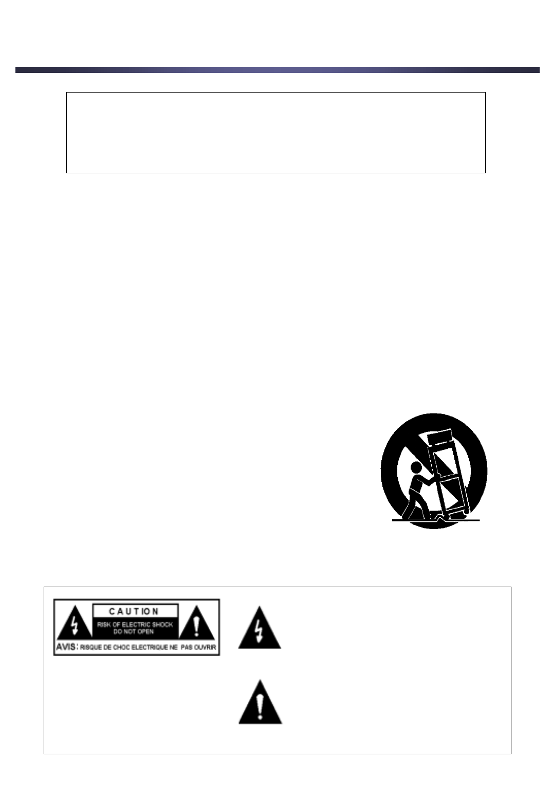
Portable cart warning
• A product and cart combination should be moved with care. Quick
stops, excessive force, and uneven surfaces may cause the product
and cart combination to overturn.
•Ventilation - Slots and openings in the cabinet are provided for
ventilation and to ensure reliable operation of the product and to
product it from overheating, and these openings must not be blocked
or covered. The openings should never be blocked by placing the
product on a bed, sofa, rug, or other similar surface. This product
should not be placed in a built-in installation such as a bookcase or
rack unless proper ventilation is provided or the manufacturer’s
instructions have been adhered to.
•Power Sources - This product should be operated only from the
type of power source indicated on the marking label. If you are not
sure of the type of power supply to your home, consult your product
dealer or local power company. For products intended to operate from
battery power, or other source, refer to the operating instructions.
The lighting flash with arrowhead symbol,
within an equilateral triangle is intended to
alter the user to the presence of uninsulated
“dangerous voltage” within the product’s
enclosure that may be of sufficient magnitude
to constitute a risk of electric shock o persons.
The exclamation point within a equilateral
triangle is intended to alert the user to the
presence of important operating and
maintenance(Servicing) instruction in the
literature accompanying the appliance.
CAUTION :
TO REDUCE THE RISK OF
ELECTRIC SHOCK. DO NOT
REMOVE COVER (OR BACK). NO
USER SERVICEABLE PARTS
INSIDE REFER SERVICING TO
QUALIFIED SERVICE PERSONNEL
2
1. Safety Instructions
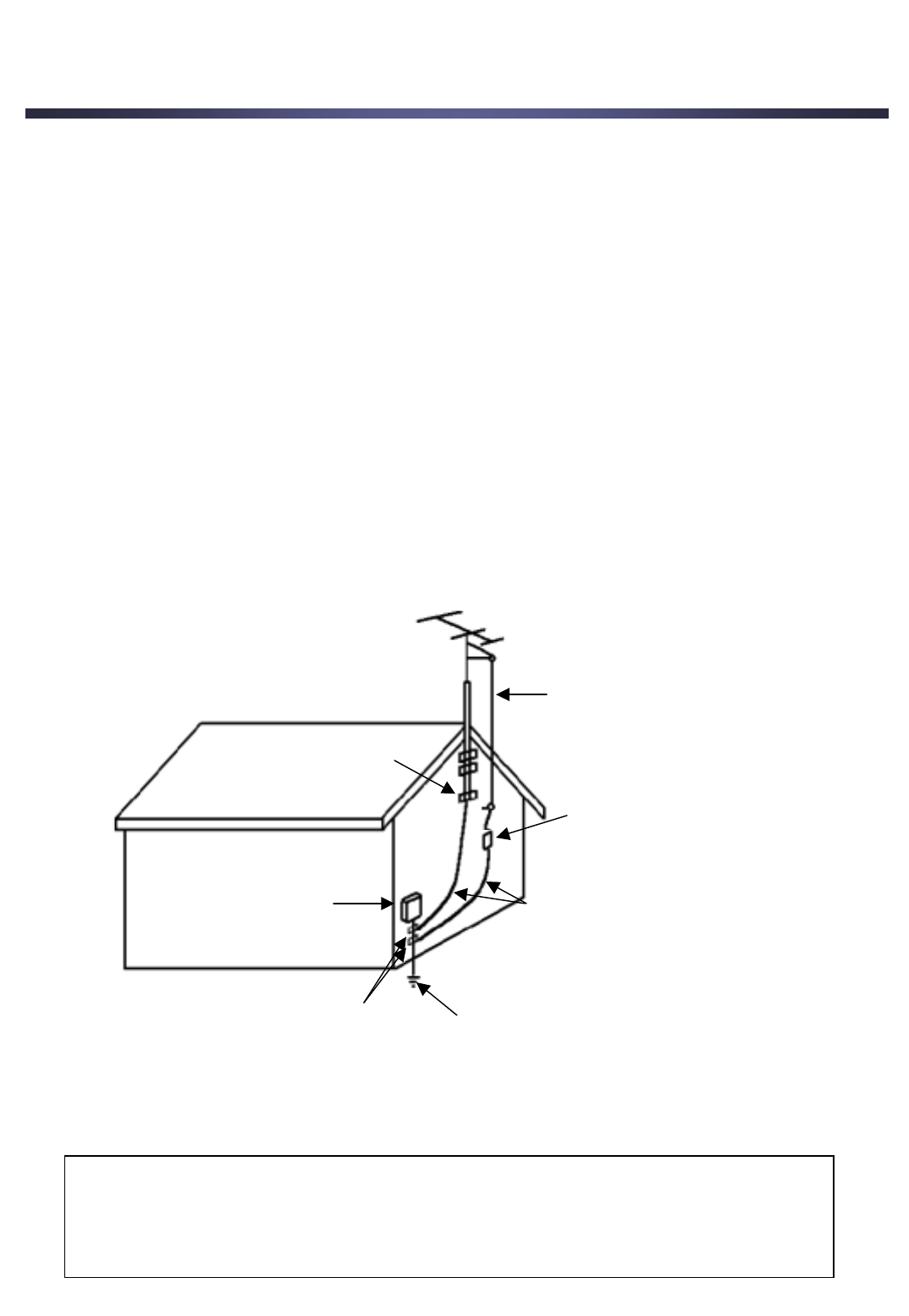
Example of Antenna grounding as per National Electric Code, ANSI/NFPA 70
(NEC – National Electrical Code)
ANTENNA LEAD IN WIRE
ANTENNA DISCHARGE UNIT
(NEC SECTION 810-20)
GROUNDING CONDUCTORS
(NEC SECTION 810-21)
GROUND CLAMPS POWER SERVICE GROUNDING ELECTRODE SYSTEM
(NEC AR 250, PART H)
GROUND CLAMP
ELECTRIC SERVICE
EQUOPMENT
Note to CATV System Installer
This reminder is provided to call the CATV system installer’s attention to Article 820-40 of
the NEC that provides guidelines for proper grounding and, in particular, specifies that the
cable ground shall be connected to the grounding system of the building, as close to the
point of cable entry as practical.
•Grounding or Polarization - This product may be equipped with a polarized alternating-current line
plug (a plug having one blade wider than the other). This plug will fit into the power outlet only one way.
This is a safety feature. If you are unable to insert the plug fully into the outlet, try reversing the plug. If
the plug should still fail to fit, contact your electrician to replace your obsolete outlet. Do not defeat the
safety purpose of the polarized plug.
•Alternate Warnings - This product is equipped with a three-wire grounding-type plug, a plug having
a third (grounding) pin. This plug will only fit into a grounding-type power outlet. This is a safety feature.
If you are unable to insert the plug into the outlet, contact your electrician to replace your obsolete
outlet. Do not defeat the safety purpose of the grounding-type plug.
•Power-Cord Protection - Power-supply cords should be routed so that they are not likely to be
walked on or pinched by items placed upon or against them, paying particular attention to cords at
plugs, convenience receptacles, and the point where they exit from the product.
•Productive Attachment Plug - The product is equipped with an attachment plug having overload
protection. This is a safety feature. See Instruction Manual for replacement or resetting of protective
device. If replacement of the plug is required, be sure the service technician has used a replacement
plug specified by the manufacturer that has the same overload protection as the original plug.
•Outdoor Antenna Grounding - If an outside antenna or cable system is connected to the product,
be sure the antenna or cable system is grounded so as to provide some protection against voltage
surges and built-up static charges. Article 810 of the National Electrical Code, ANSI/NFPA 70,
provides information with regard to proper grounding of the mast and supporting structure, grounding
of the lead-in wire to an antenna discharge unit, size of grounding conductors, location of antenna-
discharge unit, connection to grounding electrodes, and requirements for the grounding electrode.
3
1. Safety Instructions

•Lightning - For added protection for this product during a lighting storm, or when it is left
unattended and unused for long periods of time, unplug it from the wall outlet and disconnect the
antenna or cable system. This will prevent damage to the product due to lightning and power-line
surges.
•Power Lines - An outside antenna system should not be located in the vicinity of overhead
power lines or other electric light or power circuits, or where it can fall into such power lines or
circuits. When installing an outside antenna system, extreme care should be taken to keep from
touching such power lines or circuits as contact with them might be fatal.
•Overloading - Do not overload wall outlets, extension cords, or integral convenience
receptacles as this can result in a risk of fire or electric shock.
•Object and Liquid Entry - Never push objects of any kind into this product through openings
as they may touch dangerous voltage points or shout-out parts that could result in a fire or
electric shock. Never spill liquid of any kind on the product.
•Servicing - Do not attempt to service this product yourself as opening or removing covers may
expose you to dangerous voltage or other hazards. Refer all servicing to qualified service
personnel.
•Damage Requiring Service - Unplug this product from the wall outlet and refer servicing to
qualified service personnel under the following conditions.
a) When the power-supply cord or plug is damaged.
b) If liquid has been spilled, or objects have fallen into the product.
c) If the product has been exposed to rain or water.
d) If the product does not operate normally by following the operating instructions.
Adjust only those controls that are covered by the operating instructions as an
improper adjustment of other controls may result in damage and will often
require extensive work by a qualified technician to restore the product to its
normal operation.
e) If the product has been dropped or damaged in any way, and
f) When the product exhibits a distinct change in performance - this indicates a
need for service
•Replacement Parts - When replacement parts are required, be sure the service technician
has used replacement parts specified by the manufacturer or have the same characteristics as
the original part. Unauthorized substitutions may result in free, electric shock, or other hazards.
•Safety Check - Upon completion of any service or repairs to this product, ask the service
technician to perform safety checks to determine that the product is in proper operating condition.
•Wall or Ceiling Mounting - The product should be mounted to a wall or ceiling only as
recommended by the manufacturer.
•Heat - The product should be situated away from heat sources such as radiators, heat registers,
stoves, or other products (including amplifiers) that produce heat.
4
1. Safety Instructions
Instructions on Protection from ESD
The set is fitted with components sensitive to electrostatic. These can be irreparably damaged or
their service life impaired by the effect of an electric field or electrostatic discharge.
It is imperative that the following protective measures be observed for modules at risk from
electrostatic discharge.
• Before you commence work on one of the modules at risk, form an equipotential
bond between yourself and the surrounding environment. It is imperative that the
base unit be earthed via the earth terminal during this process.

FCC NOTICE
THIS DEVICE COMPLIES WITH PART 15 OF THE FCC RULES.
OPERATION IS SUBJECT TO THE FOLLOWING TWO CONDITIONS:
(1) THIS DEVICE MAY NOT CAUSE HARMFUL INTERFERENCE, AND
(2) THIS DEVICE MUST ACCEPT ANY INTERFERENCE RECEIVED,
INCLUDING INTERFERENCE THAT MAY CAUSE UNDERSIRED OPERATION.
This equipment has been tested and found to comply with the limits for a Class B digital device,
pursuant to part 15 of the FCC Rules. These limits are designed to provide reasonable
protection against harmful interference in a residential installation. This equipment generates,
uses and can radiate radio frequency energy and, if not installed and used in accordance with
the instructions, may cause harmful interference to radio communication. However, there is no
guarantee that interference will not occur in a particular installation. If this equipment does
cause harmful interference to radio or television reception, which can be determined by turning
the equipment off and on, the user is encouraged to try to correct the interference by one or
more of the following measures :
- Reorient or relocate the receiving antenna.
- Increase the separation between the equipment and receiver.
- Connect the equipment into an outlet on a circuit difference from that to which the receiver is
connected.
- Consult the dealer of an experienced radio/TV technician for help.
NOTE : The manufacturer is not responsible for any radio or TV interference caused by
unauthorized modifications to this equipment. Such modifications could void the user's authority
to operate the equipment.
5
1. Safety Instructions

2. Specifications
6
1. IF Input
Receiving Frequency Range
950MHz ~2150MHz
Input Level
-65dBm ~ -25dBm
Capture Range
+/- 5MHz
Step Frequency
125KHZ
Input Connector
"F" Female
Output Connector
"F" Female
Input Impedance
75 Ohm
Loop-through Losses
< 2dB typ
LNB Power
0/13V/18V, 22KHz on/off (400mA typ)
IF Frequency
Zero IF
IF Bandwidth
36MHz
2. QPSK Demodulator
Symbol Rate
2 to 45Ms/s
FEC Convolutional Code
Viterbi 1/2, 2/3, 3/4, 5/6, 7/8
FEC Block Code
Reed Solomon (204, 188)
Roll-off
35%
Deinterleaving
DVB ETS300421
Descrambing
DVB TES300421
3. QAM Modulator
Modulation Format
16, 32, 64, 128, 256 QAM
Maximum Symbol Rate
7.0 MBaud
Roll-off
15% (12%, 18% Programmable)
FEC Block Code
Reed Solomon (204, 188)
Scrambling
DVB ETS300429
Interleaving
DVB ETS300429
Bandwidth
8MHz
Spectrum Inversion
Programmable
2. Specifications
7
4. RF Output
Frequency range
47MHz to 862MHz Programmable
Output Level
70dBuV to 85dBuV typ
Adjustable Output Level
20dB typ
Output Loop Losses
< 2.0 dB typ
Return Losses
> 12dB typ
Connector type
"F" Female
Output Impedance
75 Ohm
C/N
> 46dB typ
Ouput Spurious Level
< -55dB typ
5. Power Supply Unit
Main AC Voltage
120V, 60Hz
Output DC Voltage & Currents
3.3V (0.6A per 6 sets)
5V (3.8A per 6 sets)
8V (1.2A per 6 sets)
12V (0A per 6sets)
22V (0.4A per 6 sets)
30V (40mA per 6 sets)
6. Dimension
W x H x D
17" x 8.7" x 10"
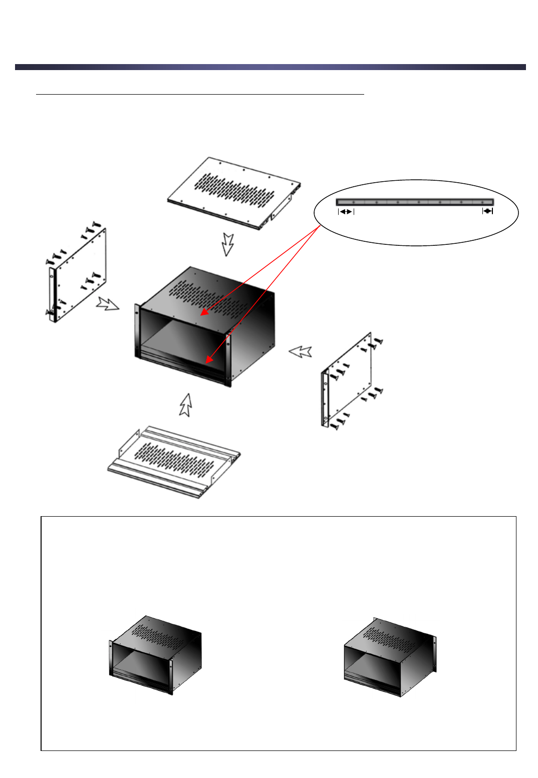
3. Assembling Instructions
1. Assemble the each board by screwing as following pictures.
Note : The section “A” is wider than the section “B” because the Power Supply
Board is lager than a Transmodulator module.
AB
[Picture 1- Rack Mount] [Picture 2- Wall Mount]
Reference : Depending on the frame location of the rack, you can use two methods.
•Rack Mount [Picture 1] – It is useful if you want to screw the rack of the unit to
other equipment.
•Wall Mount [Picture 2] – It is useful if you want to screw the rack of the unit
to the wall.
8

3. Assembling Instructions
2. Assemble the Power Supply Board first and then the Transmodulator modules from
the left side of the rack one by one with screws.
3. Connect the LNB Out to LNB In socket with loop through cable.
Connect the Power socket with the Power Connection cable.
Connect the RF In to RF Out socket with loop through cable.
9
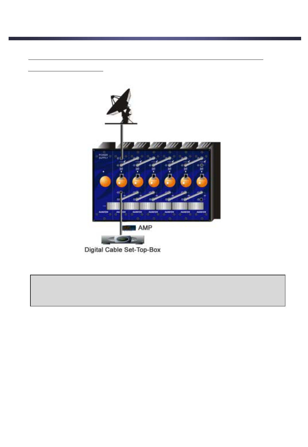
3. Assembling Instructions
4. Connect the LNB In socket of the first unit to LNB and the RF out socket to the
Digital Cable Set-top-box.
Note > You must always power on after all connections and installations are
completed.
10
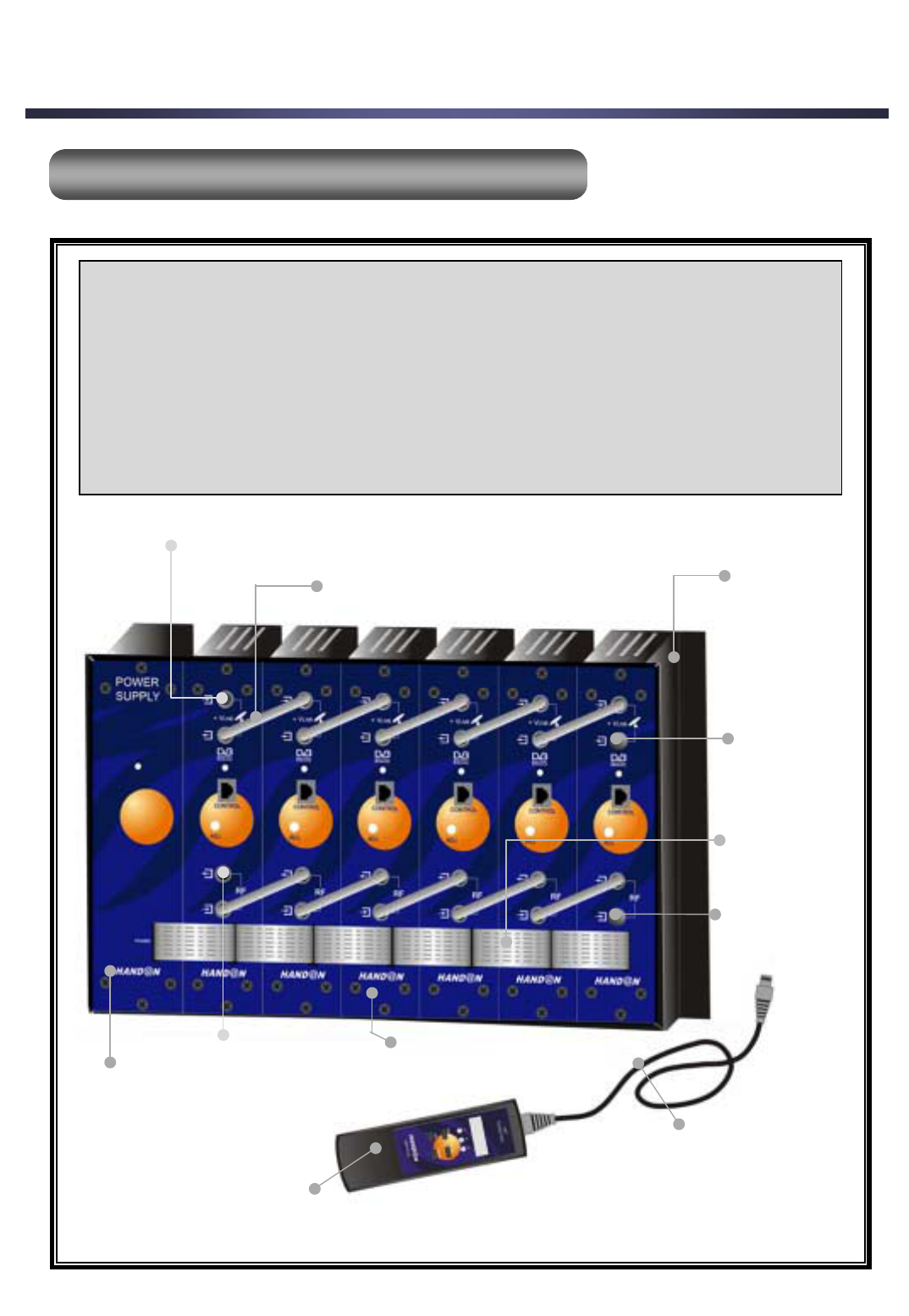
4. Descriptions
1. Overview of System compositions
1. Overview of System compositions
Rack Mount
Loopthrough Cable
HST-2000SC
HSP-2000SC
HSR-2000M
Power
Connection
Cable
HST Control Unit Cable
Termination
•HSP-2000SC : Power Supply Unit
•HST-2000SC : Transmodulator
•HSR-2000M : HST Control Unit
•Rack mount
•Accessories : Loopthrough Cable, HST Control Unit Cable, Power Connection Cable,
Termination
11
LNB Input
RF Output
Termination
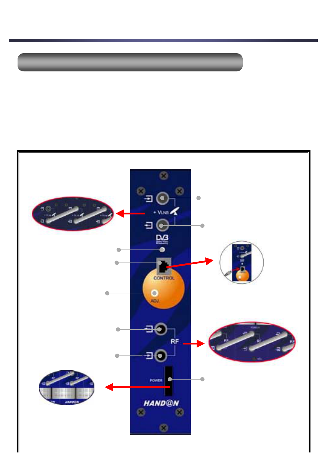
4. Descriptions
2. HST
2. HST-
-K2001Q Front View (
K2001Q Front View (Transmodulator
Transmodulator)
)
1. LNB Input
2. LNB Output
3. LED for Status Display
4. HST Control Socket
5. Power Socket
6. RF Output
7. RF input
8. Adjustable Gain
Control
The HST-2000SC receives the data from each transponder of a satellite and performs the
QPSK demodulation of the input channel containing MPEC Transport Stream.
After that, it performs the QAM modulation of MPEC Transport Stream with the data entered
through the HSR-2000M and then complete the output to the RF frequency.
It is available to select the Input frequency and the output channel using the HSR-2000M.
The descriptions of the each on the HST-2000M front are as follows.
12
4. Descriptions
1. LNB Input : It is used for receiving the data from each TP of a satellite or from
a previous unit.
2. LNB Output : It enables to supply the input signal to the next HST-2000SC, so it is
used for loop through.
3. LED for Status Display : The color of LED is changed as follows.
Power On : Orange
QPSK Lock : Red
QAM Lock : Green
4. HST Control Socket : It should be connected to the HSR-2000M.
5. Power Socket : It enables to supply the power to the HST-2000SC and should be
connected to the Power Supply Unit(HSP-2000SC).
6. RF Input : It is used to receive the data from the next HST-2000SC.
7. RF Output : It has the functionality to combine the channels before amplification
and should be connected to the RF Input of the previous HST-2000SC module.
8. Adjustable Gain Control(ADJ.) : It is set to Max. at initial situation.
You could reset the data but it is recommended to
remain the initial status.
13
4. Descriptions
3. HSP
3. HSP-
-K2002P View (Power Supply Unit)
K2002P View (Power Supply Unit)
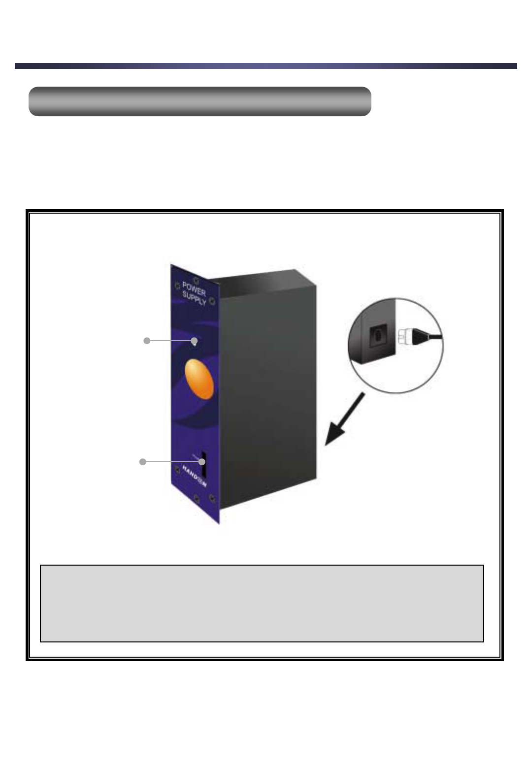
Power on LED
Power Socket
•Power on LED : The color of LED is Green when it has the input power.
•Power Socket : It should be connected to the HSR-2000M.
The HSP-2000SC is used to supply the input power with the HST-2000SC.
Because a HSP-2000SC could control just 6 HST-2000SC, if you want to use HST-2000SC
more than 6 unit, you need more HSP-2000SC power supply unit.
You could see the LED of HSR-2000M power on just when the HSP-2000SC has input power.
14
4. Descriptions
4. HSR
4. HSR-
-2000Q View (HST Control Unit)
2000Q View (HST Control Unit)
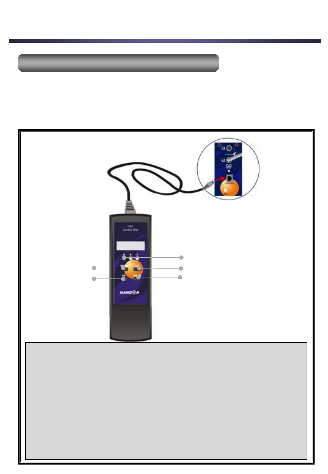
LED
UP
DOWN
MENU
OK
You could perform all programming with the below four buttons of the HSR-2000M.
It is available just when the HST-K2001Q has input power and is connected to the HSR-2000M.
Because the HST-2000SC could control only one TP, you should set the HST-2000SC
according to the number of TP which you would use.
•MENU : It is used to set the HST-2000M initially and to go to the previous menu.
If you want to set the HST-2000M, press the MENU once.
•OK : It is used to go to the next menu.
•UP : It is used to go up the data while setting.
•DOWN : It is used to go down the data while setting.
•LED : You could find the LED status to change while setting.
A B C
1) Correct Functioning : ¤¤¤
2) QPSK Demodulator Locking : ¤o ¤
3) QAM Modulator Locking : ¤¤¤
15
5. Installation
1. Before the Installation
1. Before the Installation
1-1. Preparatory Tasks
The LNB should be ready for being able to receive the signal from a satellite. Then you
should connect the LNBs input socket to the unit to receive the input frequency.
If you want to use several the HST-2000SC, you should connect the one LNBs output to
the next LNBs input with loop through cable.
You should connect between the RF input and RF output same as the above with loop
through cable.
Note > You must always power on after all connections and installations are
completed.
1-2. The Installation Procedure
You can find the [----] display when the HSR-2000M is connected to the HST-2000SC
initially.
The unit will return to the initial stage after it past one minute without any operation while
you are installing.
16
2. Installation
2. Installation
2-1. Installation Flow Chart
[----]
[LNB]
[0] / [13] / [18]
[ON] / [OFF]
[Fre]
[****]
[SR]
[**]
[****]
[good] / [err]
[256] / [128] / [64] / [32] / [16]
[****]
[****]
[----]
←Initial display
←User Selection
←User Selection
←Input the Frequency
←Input the first two digit of the Symbol Rate
←Input the rest digit of the Symbol Rate
←User Selection
←User Selection
←Display the calculated data
←Final display

5. Installation
17
2-2. Variety of LNB polarity control menu : 0/13V/18V and 0/22KHz tone
• You can find the [LNB] display on the HSR-2000M when you press the OK key initially.
• Press the OK key again to display the polarity control then select the one out of [0], [13V],
[18V] using the UP/Down keys.
• Press the OK key to confirm the previous selection and go to the next selection of the
0/22KHz tone.
• Select the [On] or [Off] using the UP/Down keys.
2-3. IF Frequency Input menu
• Press the OK key to set the input frequency data when [Fre] is displayed on the HSR-2000M.
• Press the Up or Down key till you can reach the input frequency values which you want to fix
then release the Up or Down key.
• Press the OK key to go to the symbol rate menu using the UP/ Down keys. The available
range is between 2 and 32.00Mbaud.
In case you want to set the 24.800MBaud, you should first set the [24] and press the OK key
and then set the [800] using the Up/Down keys.
If the input value coincide with the Input signal, the [good] is displayed on the display window
of the HSR-2000M after waiting for 2 or 3 seconds.
If it doesn’t coincide with, the [Err] is displayed.
2-4. Modulation format (256, 128, 64, 32, 16)
• Press the OK key to select the modulation format when the [good] is displayed.
• Select the one out of 256, 128, 64, 32 and 16 using the Up/Down keys.

2-5. RF output menu
• Press the OK key to go to the output channel menu.
You could choose the range between 52 and 858M using the Up/Down keys.
It goes up or down 8M step at one time.
• Press the OK key then the information of the QAM symbol rate is displayed.
This data is calculated according to the value of modulation format automatically and is useful
for you to know.
By pressing the OK key, you confirms to complete all procedure to install on the HST-2000M
module and at the same time all information which you set is saved.
Then it shows the [- - - -] on the display window of the HSR-2000M.
3. Adjusting the RF Output Signal Level
3. Adjusting the RF Output Signal Level
You should control the signal transmitted through the final module.
It is recommended that you should use the amplified signal from pre-amplifier.
5. Installation
18

6. Channel & Frequency Table
No. CH Freq. Cen-Fre No. CH Freq. Cen-Fre No. CH Freq. Cen-Fre No. CH Freq. Cen-Fre
1 2 55.25 57 62 W+21 421.25 423 123 W+82 787.25 789 184 72 819.25 821
2 3 61.25 63 63 W+22 427.25 429 124 W+83 793.25 795 185 73 825.25 827
3 4 67.25 69 64 W+23 433.25 435 125 W+84 799.25 801 186 74 831.25 833
4 A-8 HRC,IRC 65 W+24 439.25 441 126 14 471.25 473 187 75 837.25 839
5 5 77.25 79 66 W+25 445.25 447 127 15 477.25 479 188 76 843.25 845
6 6 83.25 85 67 W+26 451.25 453 128 16 483.25 485 189 77 849.25 851
7 A-5 91.25 93 68 W+27 457.25 459 129 17 489.25 491 190 78 855.25 857
8 A-4 97.25 99 69 W+28 463.25 465 130 18 495.25 497
9 A-3 103.25 105 70 W+29 469.25 471 131 19 501.25 503
10 A-2 109.25 111 71 W+30 475.25 477 132 20 507.25 509
11 A-1 115.25 117 72 W+31 481.25 483 133 21 513.25 515
12 A 121.25 123 73 W+32 487.25 489 134 22 519.25 521
13 B 127.25 129 74 W+33 493.25 495 135 23 525.25 527
14 C 133.25 135 75 W+34 499.25 501 136 24 531.25 533
15 D 139.25 141 76 W+35 505.25 507 137 25 537.25 539
16 E 145.25 147 77 W+36 511.25 513 138 26 543.25 545
17 F 151.25 153 78 W+37 517.25 519 139 27 549.25 551
18 G 157.25 159 79 W+38 523.25 525 140 28 555.25 557
19 H 163.25 165 80 W+39 529.25 531 141 29 561.25 563
20 I 169.25 171 81 W+40 535.25 537 142 30 567.25 569
21 7 175.25 177 82 W+41 541.25 543 143 31 573.25 575
22 8 181.25 183 83 W+42 547.25 549 144 32 579.25 581
23 9 187.25 189 84 W+43 553.25 555 145 33 585.25 587
24 10 193.25 195 85 W+44 559.25 561 146 34 591.25 593
25 11 199.25 201 86 W+45 565.25 567 147 35 597.25 599
26 12 205.25 207 87 W+46 571.25 573 148 36 603.25 605
27 13 211.25 213 88 W+47 577.25 579 149 37 609.25 611
28 J 217.25 219 89 W+48 583.25 585 150 38 615.25 617
29 K 223.25 225 90 W+49 589.25 591 151 39 621.25 623
30 L 229.25 231 91 W+50 595.25 597 152 40 627.25 629
31 M 235.25 237 92 W+51 601.25 603 153 41 633.25 635
32 N 241.25 243 93 W+52 607.25 609 154 42 639.25 641
33 O 247.25 249 94 W+53 613.25 615 155 43 645.25 647
34 P 253.25 255 95 W+54 619.25 621 156 44 651.25 653
35 Q 259.25 261 96 W+55 625.25 627 157 45 657.25 659
36 R 265.25 267 97 W+56 631.25 633 158 46 663.25 665
37 S 271.25 273 98 W+57 637.25 639 159 47 669.25 671
38 T 277.25 279 99 W+58 643.25 645 160 48 675.25 677
39 U 283.25 285 100 W+59 649.25 651 161 49 681.25 683
40 V 289.25 291 101 W+60 655.25 657 162 50 687.25 689
41 W 295.25 297 102 W+61 661.25 663 163 51 693.25 695
42 W+1 301.25 303 103 W+62 667.25 669 164 52 699.25 701
43 W+2 307.25 309 104 W+63 673.25 675 165 53 705.25 707
44 W+3 313.25 315 105 W+64 679.25 681 166 54 711.25 713
45 W+4 319.25 321 106 W+65 685.25 687 167 55 717.25 719
46 W+5 325.25 327 107 W+66 691.25 693 168 56 723.25 725
47 W+6 331.25 333 108 W+67 697.25 699 169 57 729.25 731
48 W+7 337.25 339 109 W+68 703.25 705 170 58 735.25 737
49 W+8 343.25 345 110 W+69 709.25 711 171 59 741.25 743
50 W+9 349.25 351 111 W+70 715.25 717 172 60 747.25 749
51 W+10 355.25 357 112 W+71 721.25 723 173 61 753.25 755
52 W+11 361.25 363 113 W+72 727.25 729 174 62 759.25 761
53 W+12 367.25 369 114 W+73 733.25 735 175 63 765.25 767
54 W+13 373.25 375 115 W+74 739.25 741 176 64 771.25 773
55 W+14 379.25 381 116 W+75 745.25 747 177 65 777.25 779
56 W+15 385.25 387 117 W+76 751.25 753 178 66 783.25 785
57 W+16 391.25 393 118 W+77 757.25 759 179 67 789.25 791
58 W+17 397.25 399 119 W+78 763.25 765 180 68 795.25 797
59 W+18 403.25 405 120 W+79 769.25 771 181 69 801.25 803
60 W+19 409.25 411 121 W+80 775.25 777 182 70 807.25 809
61 W+20 415.25 417 122 W+81 781.25 783 183 71 813.25 815
19