Handheld Group 1127824 Rugged Tablet PC User Manual

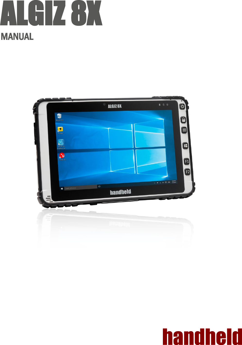
Handheld Group AB Rugged Tablet PC

User manual

  ALGIZ 8X MANUAL
Ver 1.0    2 CONTENT   1. Getting Started ......................................................................................................................................... 6 1.1 System Specification........................................................................................................................... 6 1.2Unpacking ........................................................................................................................................... 7 1.3 Description Of Parts ............................................................................................................................ 8 1.4 Hot Key For Specific Functions ......................................................................................................... 10 1.5First-time Operation ........................................................................................................................... 11 1.6 Powering On/Off ............................................................................................................................... 12 2. Quick Access through Hottab ................................................................................................................. 13 2.1 Hottab Introduction ........................................................................................................................... 13 2.2.Device ON/OFF ................................................................................................................................ 14 3. Frequently Used Settings ....................................................................................................................... 26 3.1Replacing Hot Swappable Battery ...................................................................................................... 26 3.2 Using Recovery Wizard to Restore Computer .................................................................................... 27 3.3 Docking Connector Pin Definition ...................................................................................................... 28 3.4 Expansion Port Pin Definition ............................................................................................................ 28 3.5. COM Port Definition ......................................................................................................................... 29
Ver 1.0    3 Copyright Notice Copyright © 2012 Handheld Inc., ALL RIGHTS RESERVED. No part of this document may be reproduced, copied, translated, or transmitted in any form or by any electronic or mechanical means, for any purposes without the permission of the original manufacturer in advance.  Trademark Acknowledgement Brand and product name are trademarks or registered trademarks of their respective owners.  Disclaimer Handheld Inc. reserves the right to make any product changes without notice, including circuits and/or software described or contained in this manual in order to improve product design and/or performance. Handheld Inc. assumes no responsibility or liability for the use of the described product(s), conveys no license or title under any patent, copyright, or masks work rights to these products, and makes no representations or warranties that these products are free from patent, copyright, or mask work right infringement, unless otherwise specified. Applications that are described in this manual are for illustration purposes only. Handheld Inc. makes no representation or warranty that such application will be suitable for the specified use without further testing or modification.  Warranty Handheld Inc. guarantees that all Handheld products will be free including material and workmanship defects for one year from the invoice date. If the customer discovers any defects, Handheld will, at its option, repair or replace the defective product without any charge to customers, and ship the returned product with prepaid transportation charges during the warranty time of one year. The returned product must be properly packaged in its original packaging to be qualified for warranty service. If there is a time gap of over 30 days between the date marked on the serial number and the shipping date, the one-year warranty time will then activate from the shipping date.  The third and fourth digits of the serial numbers stand for the manufacturing year and the fifth digit stands for the manufacturing month (e. g., with A for October, B for November and C for December).  For example, the serial number 1W10Axxxxxxxx means October of year 2010.    This device complies with Part 15 of the FCC Rules. Operation is subject to the following two conditions: (1) This device may not cause harmful interference, and (2) this device must accept any interference received, including interference that may cause undesired operation. This equipment has been tested and found to comply with the limits for a Class B digital device, pursuant to Part  15  of  the  FCC  Rules.    These  limits  are  designed  to  provide  reasonable  protection  against  harmful interference  in  a  residential  installation.  This  equipment  generates,  uses  and  can  radiate  radio  frequency energy and, if not installed and used in accordance with the instructions, may cause harmful interference to radio  communications.    However,  there  is  no  guarantee  that  interference  will  not  occur  in  a  particular installation.  If this equipment does cause harmful interference to radio or television reception, which can be determined by turning the equipment off and on, the user is encouraged to try to correct the interference by one of the following measures:   Reorient or relocate the receiving antenna.   Increase the separation between the equipment and receiver.   Connect the equipment into an outlet on a circuit different from that to which the receiver is connected.   Consult the dealer or an experienced radio/TV technician for help.  FCC Caution:   Any changes or modifications not expressly approved by the party responsible for compliance could void the user's authority to operate this equipment.   This transmitter must not be co-located or operating in conjunction with any other antenna or transmitter.
Ver 1.0    4 FOR PORTABLE DEVICE USAGE (<20cm from body/SAR needed) Radiation Exposure Statement: This device meets the government’s requirements for exposure to radio waves. This device is designed and manufactured not to exceed the emission limits for exposure to radio frequency (RF) energy set by the Federal Communications Commission of the U.S. Government. The exposure standard for wireless device employs a unit of measurement known as the Specific Absorption Rate, or SAR. The SAR limit set by the FCC is 1.6W/kg. *Tests for SAR are conducted using standard operating positions accepted by the FCC with the device transmitting at its highest certified power level in all tested frequency bands. FOR COUNTRY CODE SELECTION USAGE (WLAN DEVICES) Note: The country code selection is for non-US model only and is not available to all US model. Per FCC regulation, all WiFi product marketed in US must fixed to US operation channels only.
Ver 1.0    5 Safety Precautions  WARNING -Always completely disconnect the power cord from the device before you uncover the device and work on the hardware.  Do not connect the electronic device with power socket while the power is on. Sensitive electronic components can be damaged by sudden power surges. Only experienced electronics personnel are suggested to open mechanical housing.  CAUTION -Always ground yourself to remove any static charge before touching the CPU card.  The electronic devices are very sensitive to static electricity.  For safety concerns, please use a grounding wrist strap all the time. Place all electronic components in a static-dissipative surface or static-shielded bag when they are outside of the chassis.  UL Safety Announcement UL Classification: Class I mark: with respect to electronic shock; Fire and hazardous material only in accordance with the regulation of UL-60950 and CAN/CSA C22.2 No. 601.1.     Power Supply Announcement The Handheld Rugged Tablet PC Power is supplied by Power Adapter and Battery Pack, the power rating announcement and manufacturer information are listed as below. Power Notice! Please notice that the power code of adapter needs to be connected to the ground (earth).   Please push the power button for at least 4 seconds to enter sleep mode.Starting and Stopping the Tablet PC.  Power Adapter Manufacture: EDAC Power Electronics Co Ltd Model: EA10633B(01)Level IV Input Rated: 100-240Vac, 2.0A, 50-60Hz. Output Rated: DC  19V, 3.42A. Battery Pack Manufacture :JHT Electronic Co., Ltd Model: ALG8X-08A Rated: 5200mAh DC 7.6V  WARNING -Do not fix or replace battery, it may cause explosion! Only use with specified battery by following the manufacturer’s user manual’s instruction.
Ver 1.0    6 1. GETTING STARTED  1.1 System Specification System Processor Intel® Pentium® Processor N3710  (2M Cache, up to 2.56 GHz) BIOS AMI System BIOS Memory 1 x SODIMM, DDR3L 16004GB Storage SATA III 6Gb/s M.2 SSD 128GB Audio Digital Microphone with noise canceling (Internal) 1.5W Speaker (Internal)   Display Specification Size  8” (16:10) Resolution 800 x 1280 Brightness 700 cd/m2 (typ.) Touch Projected Capacitive Touch. Support Normal Mode,Rain Mode, Gloves Mode.  I/O Connectors Right Side 2x USB 3.0 , 1xMicro HDMI ,4 different types of inter-changeable I/O Port(Dummy--Deafault,LAN,COM,2D Barcode,  Bottom Side 1x Pogo-pin for Docking, 1x DC Power Jack Rear Side 1x Pogo-pin for Expansion I/O Port     Buttons and Indicators Control Button 1 x Power (Front)    1 x Touch Lock Key,1 x Menu Key, 1x Home Key, 2 programmable Function Keys LED indicators 1 x Power LED (Green) 1 x Storage(Green) 1 x Battery (Green & Red) 1 x Configuration (It should be off unless configured by the user.)
Ver 1.0    7 1.2  Unpacking  Check and identify the supplied accessories: Tablet Computer           Standard Battery      Power Adapter             Power Cord and Plugs
Ver 1.0    8 1.3 Description Of Parts Front:              Left:     No Item Description 1 Front Camera 2 Megapixel Webcam 2 LED Indicators:  Front LED Indicators Detail: Show the current status of the Tablet Computer 3 Touch Screen Display and act as one of the inputs for the Tablet Computer 4 Power Button Power on/off tablet 5 Touch Lock Touch mode select and touch screen lock to prevent input. 6  Menu Button Hottab Quick Access 7 Home Button Windows Start Menu 8 F1 Button Programmable function key configured by Hottab Utility 8 F2 Button Programmable function key configured by Hottab Utility 9 Digital Microphone With noise canceling function. 10 USB 3.0 High speed USB port connects to USB devices, such as USB flash drive, mouse, keyboard, printer, etc. 11 Micro HDMI HDMI output to external display 12 Changeable I/O Port Adapter port for LAN/RS232/2D Barcode Reader. Default is dummy.
Ver 1.0    9  Rear:              Bottom:         No Item Description 13 Rear Camera 8MP with Autofocus 14 Service Windows For WWAN Card 15 Expansion Port Provide optional connectivity to custom modules for special application. 16 Main Battery Slot For Main Battery pack. 17 MicroSD  & Micro SIM Card Port Memory card & SIM card reader port  18 Power Jack DC-IN power input jack 19 Docking Connector Port to docking solutions such as vehicle docking to provide power
Ver 1.0    10 1.4 Hot Key For Specific Functions For the physical buttons on the ALGIZ 8X tablet computer, in addition to their dedicated functions detailed in the previous section, they can also be used to emulate commonly used keyboard key strokes. Under different scenario, a single physical button or a combination of physical buttons provide different keyboard key strokes, which are specified below:  During POST (before Windows boots up):      During Windows:        Buttons Keystroke Menu F7 to enter BIOS setup screen F1 Recovery Menu F2 ESC Menu + F1 Enter   Buttons Keystroke Power Power ON/ OFF Touch Lock Touch mode select and touch screen lock to prevent input. Menu  Hottab Quick Access Home Normal start menu Quick Access F1 Default: Web Browser F2 Default: Windows 10 Action Center    LED Indicators: Item  Description Power Indicator  Green – Tablet is ON No light – Tablet is OFF Battery Status  Orange – AC adapter is plugged in and charging Green – AC adapter is plugged in and battery is full charged  Solid Red - Low battery (<10%) Blinking Red – Battery is being hot swapped. No light – Battery is in use and more than 10% Disk Activity Indicator  Green - Disk Activity No light - Disk Idling Configuration)  It should be off unless configured by the user.
Ver 1.0    11 1.5  First-time Operation Inserting Battery Pack To insert the standard battery pack into the Tablet Computer: 1.  Disconnect AC adapter and power cord from the tablet computer. 2.  Turn the tablet computer over, back facing up. 3.  Insert the battery on the connector-pins side first, and then lower the battery into the battery compartment. Continue to hold the Battery before battery is fully inserted. 4.  Make sure the battery is completely lowered into the compartment before letting go the Battery will be flat against the housing once fully inserted          Removing the Battery Pack 1.  Power off the tablet computer (or put it to sleep). Disconnect any cords connected to the computer. 2.  Turn the tablet computer over, back facing up. 3.  Lift the battery out using the opening on side of battery compartment.  Connecting to Power Supply The Tablet Computer operates either on external AC power or internal battery power. It is recommended to use AC power when you start up the Tablet Computer for the first time.  CAUTION - Use only the AC adapter included with your Tablet Computer. Using other AC adapters may damage the Tablet Computer and the Battery. CAUTION - For users start up the Tablet Computer for the first time with internal battery power, please make sure the battery is full charged before using. Perform the following to connect the Tablet computer to AC Power: 1.  On the side of the Tablet computer, lift the I/O protective cover by pulling on the latch 2.  Plug the DC cord of the AC adapter into the Power Jack of the tablet computer. 3.  Plug the AC power cord into the AC adapter. 4.  Finally, Plug the AC power cord into the electrical outlet.   When the AC Adapter is connected, the battery pack starts charging. The battery LED indicator on the tablet computer would show different states. Please refer to description of LED indicator on Description of Parts
Ver 1.0    12 1.6 Powering On/Off Powering On Press and hold the power button for 3.5 seconds until the blue LED power indicator light up. _________________________________________________________________________________________________________________________________________________ NOTE  Do not press the power button repeatedly.  Do not perform the following operations until the Disk Activity Indicator off o Connecting or disconnecting the AC adapter o Pressing the power button o Touching the tablet buttons, screen, or external keyboard/mouse __________________________________________________________________________________________________________________________________________________  Powering Off Perform the following procedure to power off the Tablet Computer: 1.  Make sure you have closed any programs that are open on the Desktop. 2.  Under Windows 10 OS, click the Start menu, you'll see a lengthy pop-up shortcut menu. 3.  Tap on Power. 4.  Tap on Shut Down. 5.  Wait for Tablet Computer to power off.  NOTE The computer will forcibly be powered off if the power button is pressed and held for 6 seconds or longer.
Ver 1.0    13 2. QUICK ACCESS THROUGH HOTTAB  2.1Hottab Introduction Hottab provides quick access to the tablet’s functions and features, such as setting up shortcuts, using camera, powering on/off built-in devices, programming function key, and changing power management. As Windows starts up, Hottab starts and runs in the background. To display the Hottab control utility, press the  (Menu) Button located on the front panel, or launching the Hottab Utility application.  (Menu) Button on the Front Panel:      Hottab Utility Icon:    The main user interface is located on the right side of the screen. There are 3 main menu options: Device ON/OFF, Settings and Touch Lock. Operations and functions on each menu options is explained in detail in the coming section.           Device button enables/disables tablet computer’s hardware functions. The configurable functions are WWAN(3G/4G/LTE), GPS, Camera, GPS/WWAN Antenna routing and Touch mode options.   Setting button provides users information such as PC Information, Battery status, and also device settings such as power management setting, and function key mappings.   Disable the double click and front panel OSD functions.
Ver 1.0    14 2.2.  Device ON/OFF This section provides a quick access to set-up built-in devices, including turning on/off RF modules, camera module and setting up touch mode.
Ver 1.0    15 Using the Wireless WAN (3G/LTE) feature Insert SIM card (For Optional 3G/LTE equipped device) CAUTION - Please power off the tablet before installing the 3G/LTE module and Micro SIM card, or the tablet computer might be damaged by the incorrect installation behaviors. The Tablet Computer supports data connection with 3G/LTE modules and fits Micro-SIM card. (Note: 3G/LTE feature is optional). Before using the data connection program, please perform the following procedures to insert the Micro-SIM card to your Tablet Computer: 1.  Power off the Tablet Computer. 2.  Remove the service window in the rear by unscrewing four screws. 3.  Remove the screw that is securing the 3G/LTE module. 4.  Carefully lift the 3G wireless module up, and be cautious not to damage the connected cable. 5.  Make sure the SIM card IC contact patch is faced down, notch is in the direction of insertion (towards right).                 Micro SD Card
Ver 1.0    16 Use Wireless WAN Feature For tablets equipped with wireless WAN (3G or 4G/LTE) card, to use the wireless WAN feature to connect to the network, perform the following procedure: 1.  Open the Hottab utility by press the (Menu) Button located on the front panel, OR launching the Hottab Utility application. 2.  Tap on the Device ON/OFF button. 3.  Check the status color of the WWAN icon: Item   Status Color Description  Orange WWAN (3G/4G) is enabled. White WWAN (3G/4G) is disabled.  4.  If the WWAN feature is disabled (white), tap on the WWAN icon to enable it (orange). 5.  You can check the wireless WAN connection status through the wireless network connection status icon in the Windows notification area. The more bars encompassed, the better the signal is. NOTE - For the Windows 10 operating system, you also can check the Access Connections gauge, the Access Connections status icon, or the Access Connections wireless status icon in the Windows notification area.       Using the GPS feature To enable the wireless GPS feature, perform the following procedure: 1.  Open the Hottab utility by press the  (Menu) Button located on the front panel, OR launching the Hottab Utility application. 2.  Tap on the Device ON/OFF button. 3.  Check the status color of the GPS icon: Item   Status Color Description  Orange GPS is enabled. White GPS is disabled.    4.  If the GPS feature is disabled (white), tap on the GPS icon to enable it (orange). 5.  Now the GPS feature is ready to be used with an application utilizing the GPS.
Ver 1.0    17 Using Camera Features This Hottab menu option allows users take a picture or record a video. Before use, make sure the Camera is powered on under Devices menu with the following scenarios: 1.  Open the Hottab utility by press the  (Menu) Button located on the front panel, OR launching the Hottab Utility application. 2.  Tap on Device  button to check the built-in devices status. 3.  Check the status color of the Camera icon: Item   Status Color Description  Orange Camera is enabled.   White Camera is disabled.   4.  If the Camera feature is disabled (white), tap on the Camera icon to enable it (orange). 5.  Go back to the Hottab main menu by pressing the  (Menu) Button located on the front panel OR click on the back arrow on top. 6.  Tap on the HotTabCamera  shortcut to go into the Camera menu. The Camera user interface will take up the entire screen as shown below:         Description of Camera User Interface Buttons:   No Item  Description 1 Review  Preview the take picture.  2 Settings  Brings up Camera settings page.Available Settings:   Photo format: modify/inspect saved location for pictures.   Rear Video Resolution: Picture compression quality.   File Location: Opens the location where pictures and videos are saved in a window. 3 Switch Camera  Switches the front or rear camera device.  4 Flash Control  Enable/Disables LED Flash when taking picture.  5 Video Record  Video Record Button. Tap to Start, and press again to stop recording.
Ver 1.0    18 6 Shutter  Camera Shutter Button. Tap to take picture.  7 Exit  Exits the Camera and hide Hottab Utility.
Ver 1.0    19 Turn on/off the GPS Ext. Antenna  CAUTION - The vehicle dock of ALGIZ 8X Tablet PC supports external GPS antenna through standard SMA connector. To work with external GPS antenna, please make sure the tablet PC is well installed to vehicle dock, and the vehicle dock has connected with external GPS antenna. When working with vehicle dock connecting to external antenna, user can switch GPS antenna from the internal one to the external one from Hottab menu. To enable/disable the External GPS Antenna, perform the following procedure: 1.  Open the Hottab utility by press the (Menu) Button located on the front panel, or launching the Hottab Utility application. 2.  Tap on the Device icon. 3.  Check the status color of the External GPS icon: Item Status Color Description  Orange GPS Ext. Antenna is enabled, and using external antenna if available White GPS Ext. Antenna is disabled, and using built-in antenna  4.  If the External GPS antenna is disabled (white), tap on the External GPS icon to enable it (orange).   Switch Touch Modes The tablet’s advanced capacitive touchscreen has 3 built-in operating modes, for users to choose under different usage scenarios:
Ver 1.0    20 To switch between the different touchscreen modes via the HotTab utility, perform the following procedure: 1.  Open the Hottab utility by press the  (Menu) Button located on the front panel, OR launching the Hottab Utility application. 2.  Tap on the Device button. 3.  Check the status color of the Touch Set icon: Item Status Color Description  White Switch between the different modes available.
Ver 1.0    21 Setting This Hottab menu option provides users information such as PC Information, Battery status, and also device settings such as power management setting, and function key mappings. Perform the following procedure to access the Hottab Setting menu: 1.  Open the Hottab utility by press the  (Menu) Button located on the front panel, OR launching the Hottab Utility application. 2.  Tap on the Settings button. 3.  Below shows the items listed in Settings Menu.  PC Information: This section provides user device information in regards to BIOS Version, EC Versions, Hottab Versions, OS Versions, as well as Unit Serial Number, shown in the picture sample.        Battery Information: This section provides user battery Information.  Main Battery:The main battery Icon displays the battery level in percentages (0 to 100%). Backup Battery: (Optional)The backup battery used for battery hot swapping displays its state in text with the following meanings.   Status Description  High Backup battery is fully charged, and can be used for hot swapping  Medium Backup battery level is intermediate, but can be used for hot swapping  Low Backup battery level is low, and hot swapping is not recommended.  Battery Charge Time:The Battery Information also displays estimated time needed to fully charge the main battery when AC adapter is plugged in. Meanwhile, the backup battery is charged by the main battery.
Ver 1.0    22 Using the physical function keys (Hotkeys) The function key mapping menu option allows user to change the physical function buttons, F1 and F2. Users can change what application will be launched with short press or long press of keys.     To configure function key mapping, perform the following:   1. Open the Hottab utility by press the        (Menu) Button located on the front panel, or launching the Hottab Utility application. 2. Tap on the Setting button. 3. Tap on function key icon for the corresponding key that you want to change. 4. At top of utility, it will say “Short Press” or “Long Press” to indicate what type of press is being configured 5. You can switch what type of press you want to configure by tapping on the “Short Press” or “Long Press” icon at the bottom of the utility window. 6. Pick from list of preset applications by tapping on the application icons OR customize which application to execute using the picker.  Using the Custom picker: 1. Tap the         icon to reveal browser window           2. Navigate to the desired executable to map to function key                                                     3. Tap on “Done” to save selection.  To map the function key to another application: 1.  Tap on the   icon to remove connection to the original application, and pick again tapping on  icon.  Using the physical function keys: 1.  While operating the tablet, click on the physical function keys to activate functions mapped via the setup in this section.
Ver 1.0    23 Adjust the Brightness Level   The panel brightness can be adjusted from Hottab menu. To adjust the brightness, perform the following procedure: 1.  Open the Hottab utility by press the (Menu) Button located on the front panel, or launching the Hottab Utility application. 2.  Tap on the Setting button. 2. 3.  Tap on the Brightness       icon:
Ver 1.0    24 How to disable automatic brightness adjustments For computers with a light sensor, Windows 10 has the ability to automatically adjust the screen brightness depending on the ambient light levels. This feature can be more annoying than helpful, either leaving your screen too dark or frequently adjusting the brightness levels. Here’s three ways to disable the Ambient light sensor 1: using the systems setting Open the Windows start menu and click on ‘Settings’         1. In the settings window, click on ‘System’         2. The ‘Display’ menu should selected on the left, if it is not – click on‘Display’ 3. Turn the ‘Change brightness automatically when lighting changes’ to ‘Off’ 4. Click ‘Apply’ to save the changes.
Ver 1.0    25 Adjust the Volume Level The volume level can be adjusted fromHottab menu. To perform volume adjustment. The adjustment slide bar will appear on screen transparently. Tap on the right side of the bar to increase the volume and Tap on the left side of the bar to decrease the volume .Open the Hottab utility by press the  (Menu) Button located on the front panel, or launching the Hottab Utility application. 1.  Tap on the Setting button. 2.  Tap on the Volume      icon:
Ver 1.0    26 3. FREQUENTLY USED SETTINGS  3.1  Replacing Hot Swappable Battery The tablet computer supports hot-swapping of batteries, meaning the tablet doesn’t need to be powered off in order to replace the main battery. To support such mechanism, there is a backup battery inside the tablet that is charged up with the main battery. This backup battery cannot be removed, and needs to have adequate power for hot swapping of main battery to be done without issue. When the backup battery is fully charged, it can sustain up to 5 minutes of runtime to allow for battery hot-swapping.  Perform the following to hot swap the batteries: 1.  While the tablet is powered on, go to Hottab utility to check on the power level of the Backup battery. 2. If the Backup battery level is at “Low”, please charge the tablet with AC Power until the Backup battery level is at “Medium” or “High”, and do not remove the main battery. 3. If the Backup battery level is at “Medium” or “High”, continue to remove the main battery. 4.  Insert a new charged up removable battery into the battery compartment. 5.  Go to Hottab utility to check if Main battery level can be correctly read. If not, check if the new removable battery is inserted properly. 6.  If Main battery level can be read, continue to use the tablet computer.  CAUTION - To keep battery health and prevent possible issues from battery over-discharged, please charge the tablet built-in back-up battery once for every 2 months.
Ver 1.0    27 3.2 Using Recovery Wizard to Restore Computer ALGIZ 8X tablet computer has a dedicate recovery partition stored on the hard drive of the tablet to enable quick one-key recovery process. This partition occupies about 11GB of the storage space, and comes built-in to each ALGIZ 8X tablet computer. WARNING - Before starting the recovery process, be sure to backup all user data, as all data will be lost after the recovery process. Follow the procedure below to enable quick one-key recovery procedure: 1.  Plug-in the AC adapter to ALGIZ 8X tablet computer. Make sure the ALGIZ 8X tablet computer stays plugged in to power source during the recovery process. 2.  Power on the tablet computer, and when the boot screen shows up, press the F1 button (Recovery Key) on the front bezel or press F6 when using an external USB keyboard to initiate the Recovery Wizard. 3.  The following screen shows the Recovery Wizard. Click on “Recovery” button to continue.    4.  A warning message about data loss will show up. Make sure data is backed up before recovery, and click on “Yes” to continue.  5.  Wait till the recovery process to complete. During the recovery process, a command prompt will show up to indicate the percent of recovery process. After recovery is completed, and the tablet computer will restart automatically.
Ver 1.0    28 3.3 Docking Connector Pin Definition ALGIZ 8X tablet computer supports one 20-pin docking connector at the bottom side. The pin definition is listed as the following table. 20 Pin Docking Connector   Pin No. Description Pin No. Description 1 DOCK1_USB_P 11 GND_WWAN 2 DOCK_DET# 12 GND_WWAN 3 DOCK1_USB_M 13 ANT_GPS 4 DOCK_USB_P 14 GND_WWAN 5 GND 15 ANT_SEL_DET 6 DOCK_USB_N 16 GND_GPS 7 DOCK_PWR 17 GND_GPS 8 GND 18 ANT_WWAN 9 DOCK_PWR 19 DETECT- 10 DOCK_PWR  GND_GPS   3.4Expansion Port Pin Definition ALGIZ 8X tablet computer supports one optional 19-pin expansion port at the rear side. The pin definition is listed as the following table. 19 Pin Docking Connector   Pin No. Description Pin No. Description 1 POGO_PWR 11 GND 2 USB3V_POGO 12 USB_D4- 3 POGO_PWR 13 USB_D4+ 4 POGO_PWR 14 GND 5 USB5V_POGO 15 FK_CTS2 6 DET 16 DETECT_POGO 7 FK_SOUT2 17 GND 8 GND 18 FK_RTS2 9 FK_SIN2 19 DET 10 GND
Ver 1.0    29 3.5. COM Port Definition ALGIZ 8X tablet computer uses Hottab utility for built-in peripherals control. All the COM port numbers have been defined in the OS image coming with the package. COM Port Device COM 1 RS232 at I/O COM 2 RS232 of Expansion Port (optional) COM 3 GPS  COM 11 RS232 at Docking (optional) COM 12 RS232 at Docking (optional)  For some special applications, user might re-install OS and lose the COM port settings. To make sure the features works properly with Hottab utility, please follow the procedure below to re-define the COM port numbers: 1.  Go to "Device Manager", right click on the COM number need to be changed, and tap on "Properties" to open the setting page.
Ver 1.0    30 2.  Tap on "Port Setting" tab and click on "Advanced" button.                 3.  Tap on the dropdown list and choose the correct COM Port Number (refer to the COM Port Definition Table), and click "OK".             4.  Double check "Device Manager" to make sure the COM Port number has been re-defined successfully, and then restart the system.

Navigation menu