Handlink Technologies AP-100 AP-100 Smart Wi-Fi Access Point User Manual
Handlink Technologies Inc. AP-100 Smart Wi-Fi Access Point Users Manual
UserManual.wiki
>
Handlink Technologies
>
AP 100 User Manual
Users Manual
Navigation menu
Upload a User Manual
Namespaces
Wiki Guide
HTML
PDF
Info
Views
User Manual
Discussion / Help
Navigation
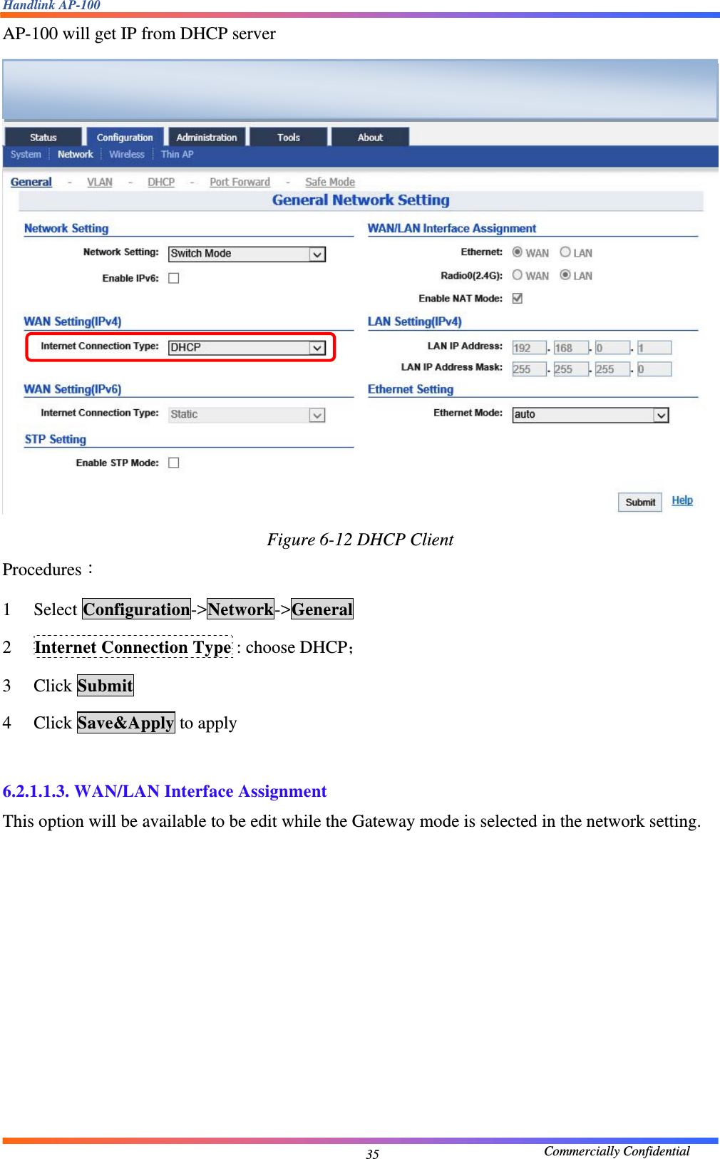
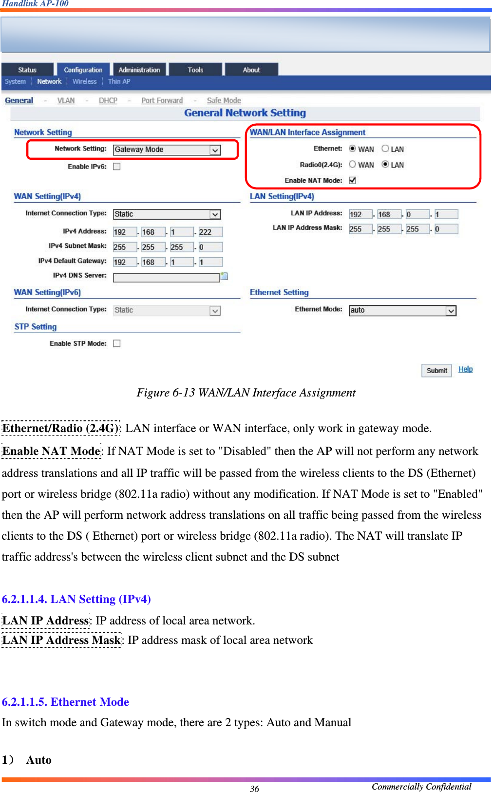
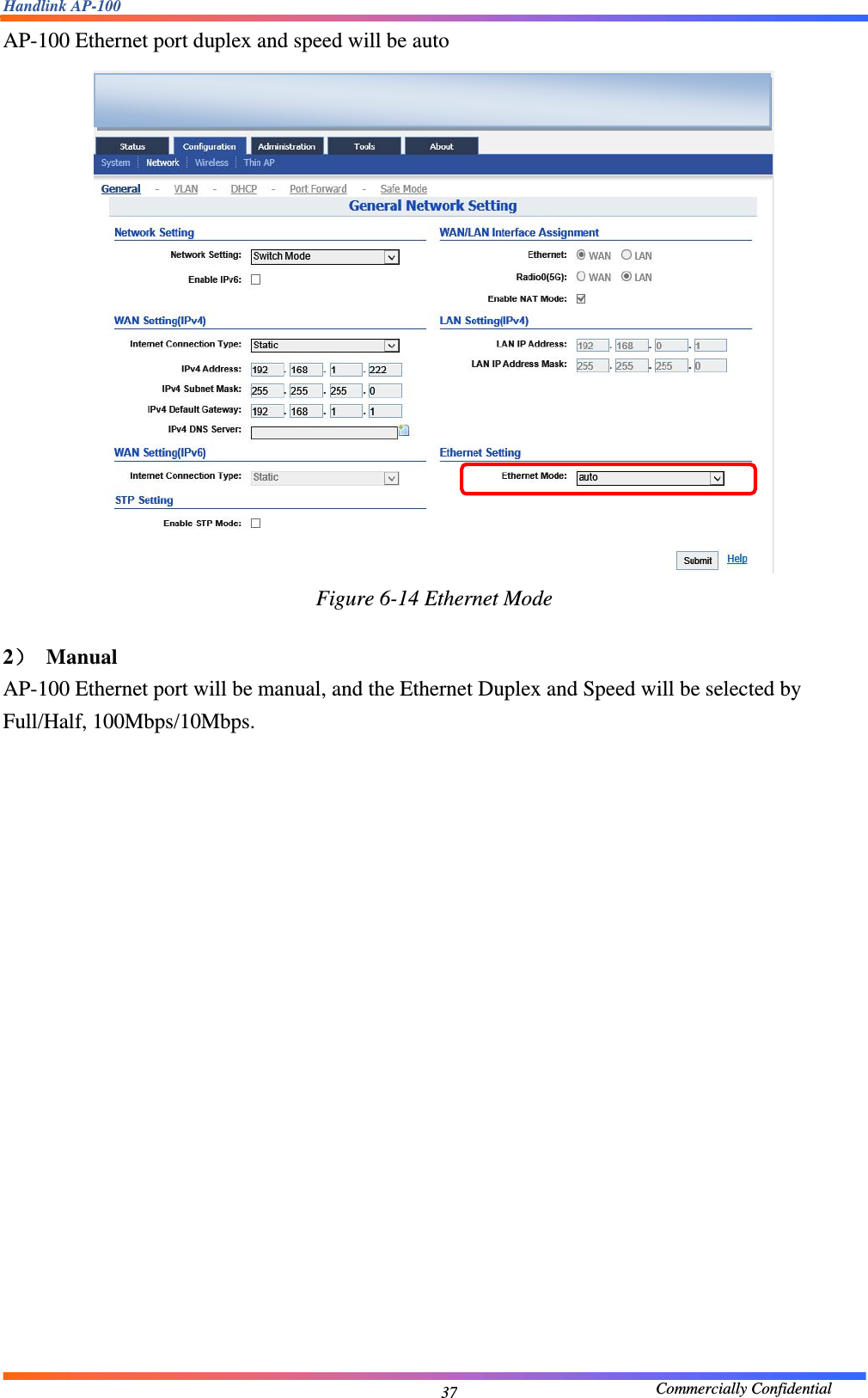
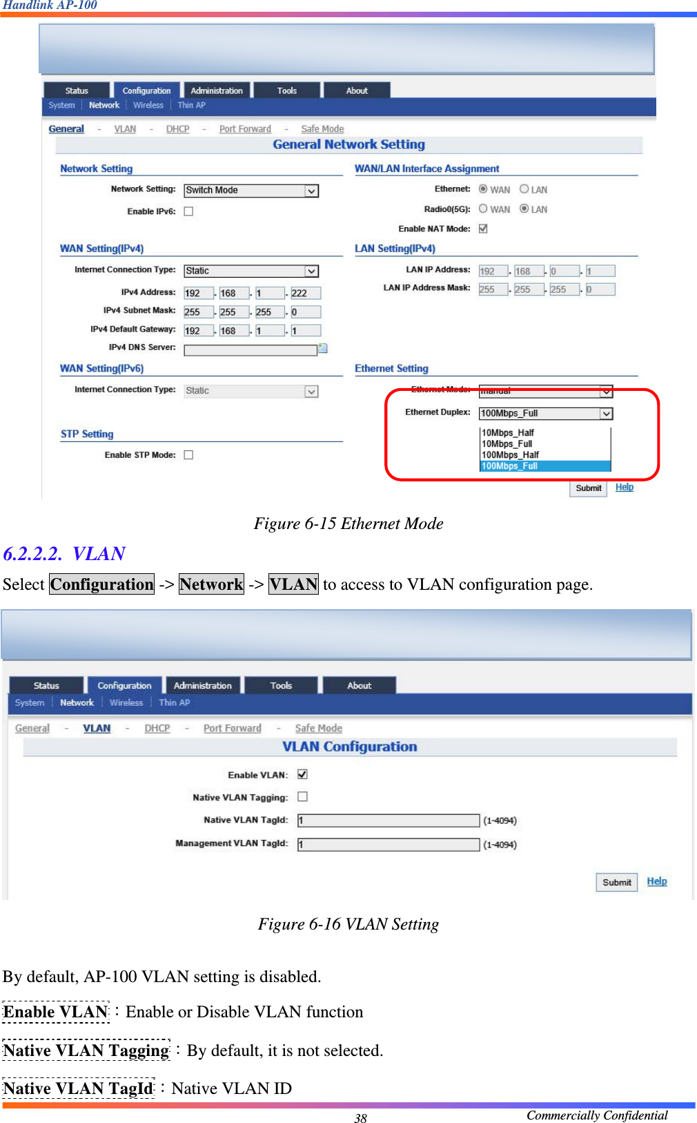
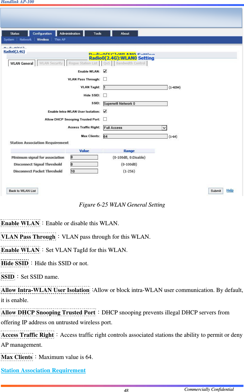
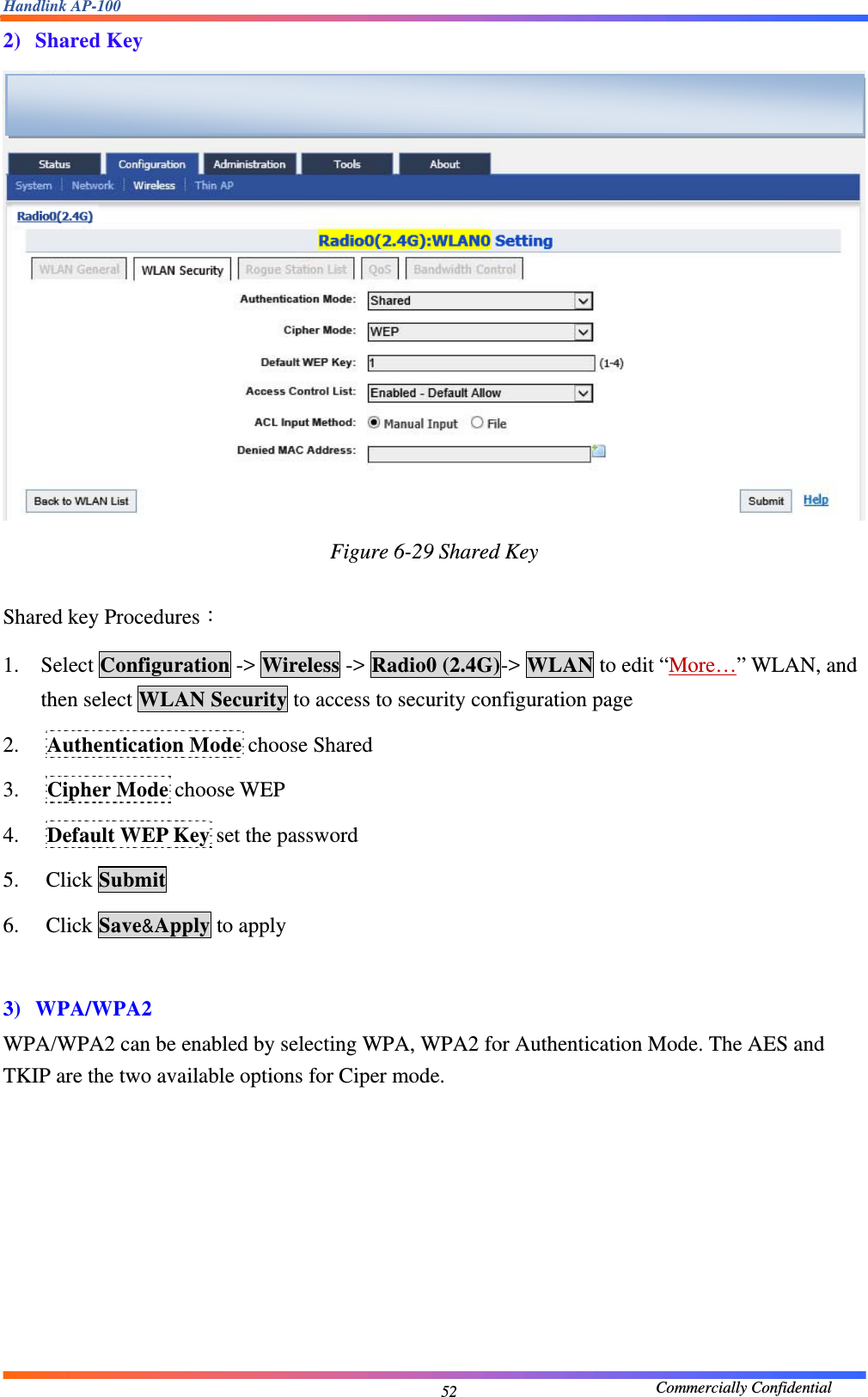
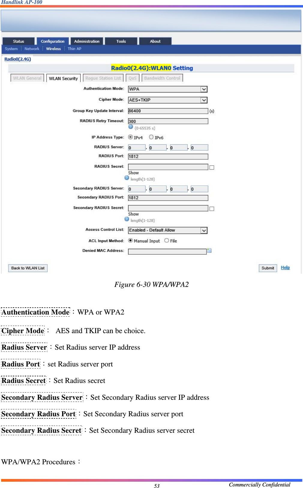
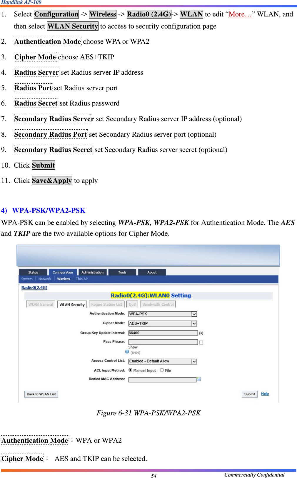
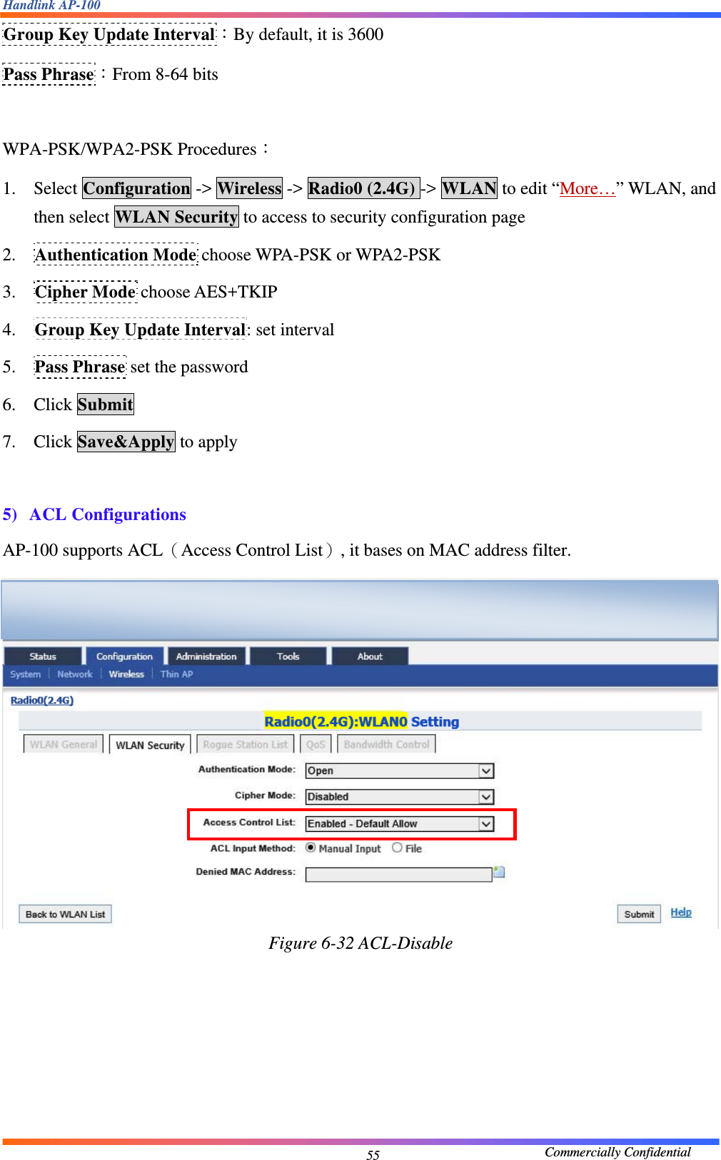
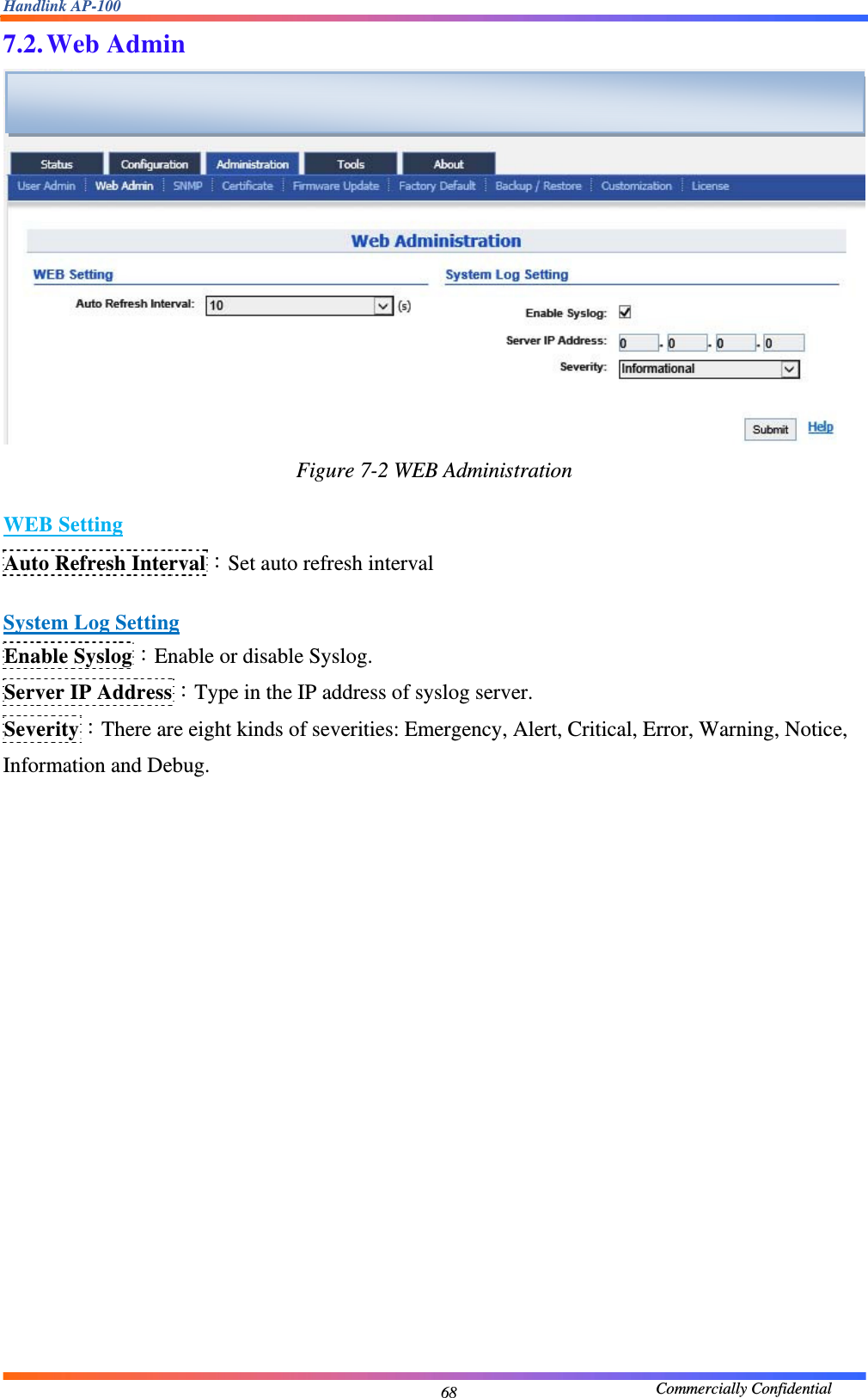
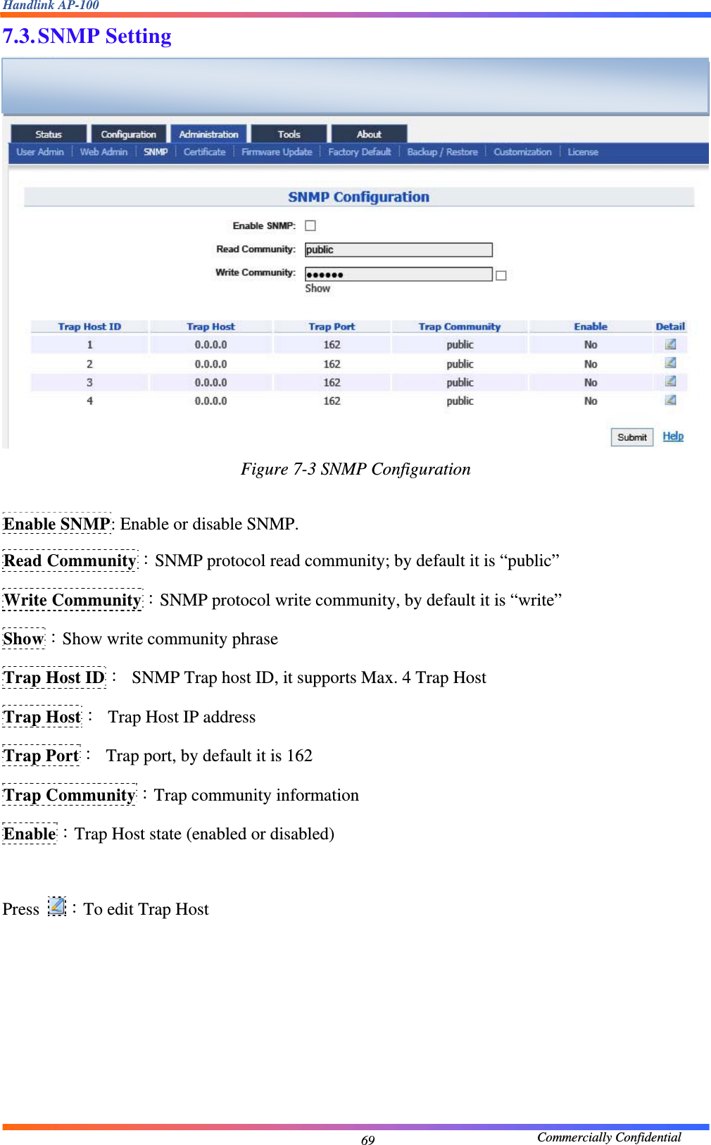
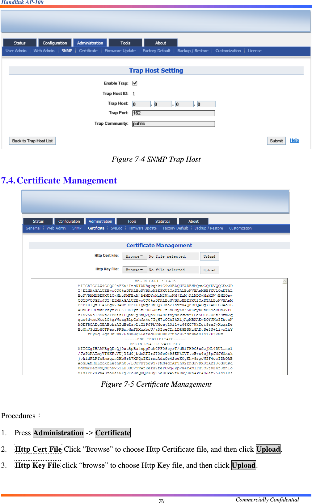
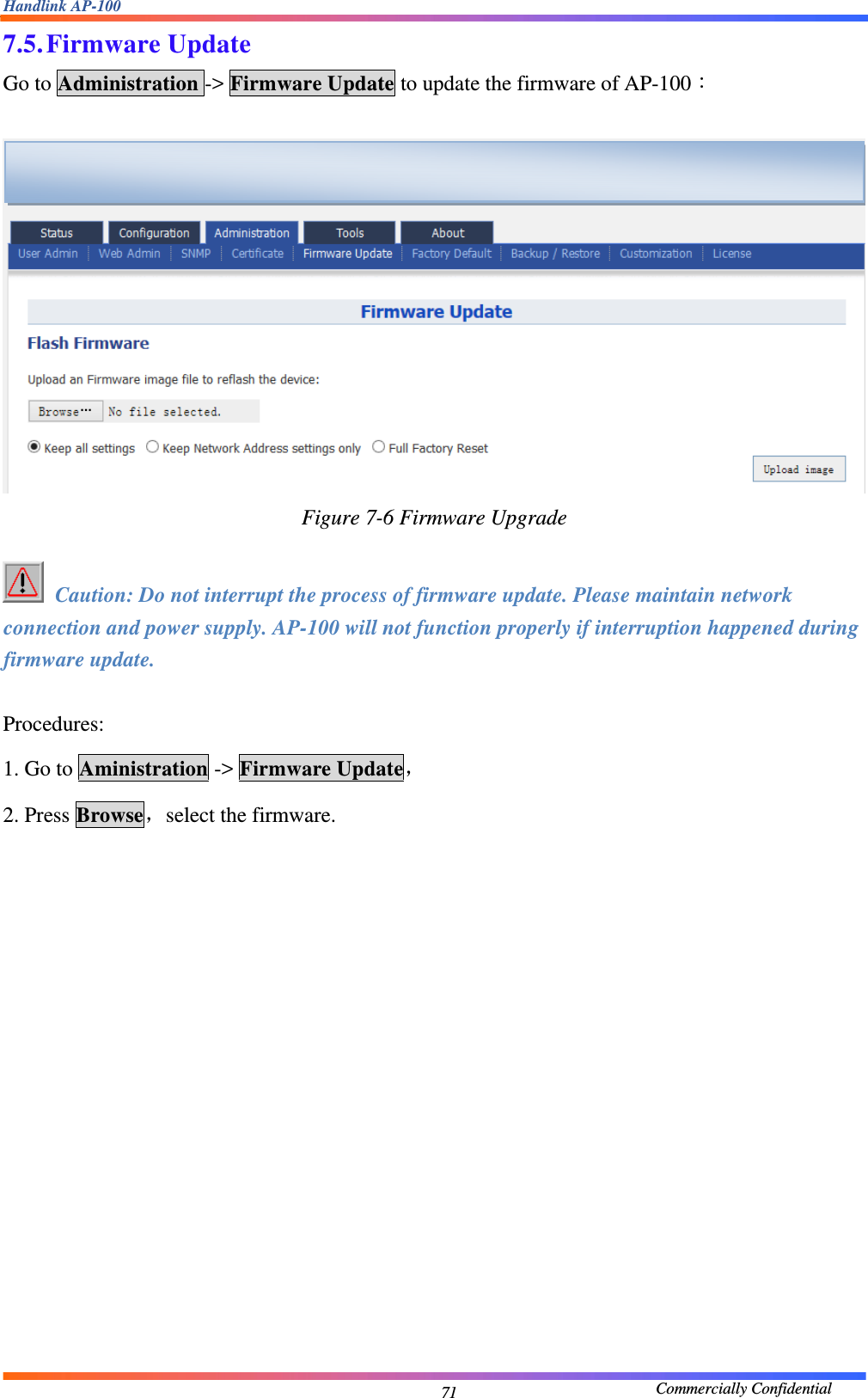
![Handlink AP-100 Commercially Confidential 6 Manual Conventions Bold Bold type within paragraph text indicates commands, files names, directory names, paths, output, or returned values. Italic Within commands, italics indicate a variable that the user must specify.Titles of manuals or other published documents are also set in italics. _____ Underline means that you have to pay attention to the words. Courier The courier font indicates output or display. [ ] Within commands, items enclosed in square brackets are optional parameters or values that the user can choose to specify or omit. { } Within commands, item enclosed in braces are options which the user must choose from. | Within commands, the vertical bar separates options. … An ellipsis indicates a repetition of preceding parameter. > The right angle bracket separates successive menu selection. NOTE: This message denotes neutral or positive information that calls out important points to the text. A note provides information that applies only in special cases. Caution: Cautions call special attention to hazards that can cause system damage or data corruption, to a lesser degree than warnings. Warnings: Warnings call special attention to hazards that can cause system damage, data corruption, personal injury, or death.](https://usermanual.wiki/Handlink-Technologies/AP-100/User-Guide-2090868-Page-6.png)