HandyWave HPS-120 Wireless Serial Adapter User Manual UserMan
HandyWave Co., Ltd. Wireless Serial Adapter UserMan
UserManual.wiki
>
HandyWave
>
HPS 120 User Manual
UserMan
Navigation menu
Upload a User Manual
Namespaces
Wiki Guide
HTML
PDF
Info
Views
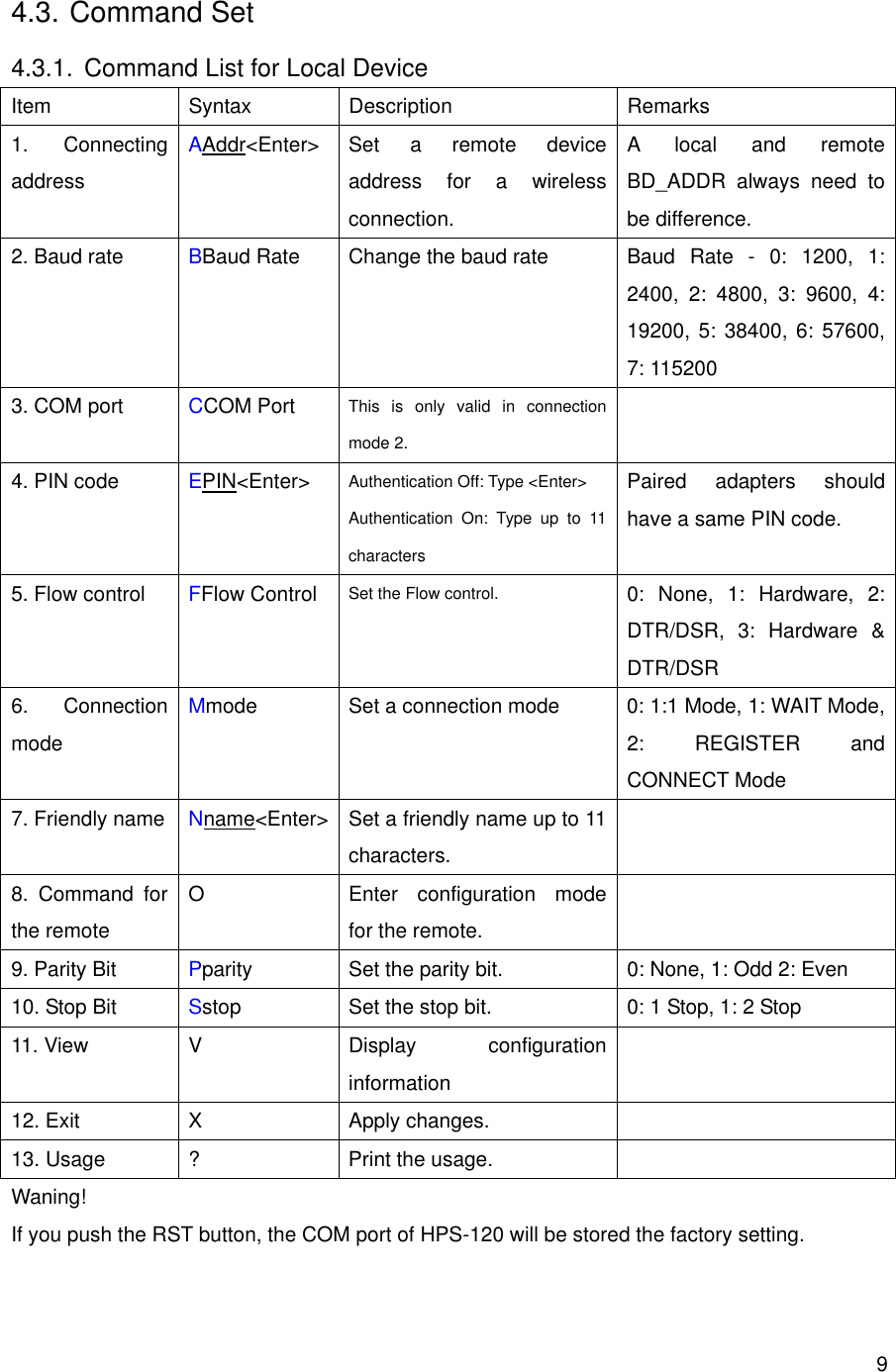
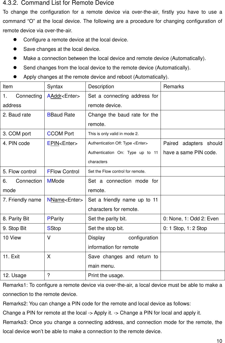
User Manual
Discussion / Help
Navigation