Hangzhou AiXiangJi Technology TYWE3S WiFi Module User Manual TYWE3S EN V1x
Hangzhou AiXiangJi Technology Co., Ltd. WiFi Module TYWE3S EN V1x
UserManual.wiki
>
Hangzhou AiXiangJi Technology
>
TYWE3S User Manual
>
Users Manual
Contents
1.
Users Manual
2.
User Manual
Users Manual
Navigation menu
Upload a User Manual
Namespaces
Wiki Guide
HTML
PDF
Info
Views
User Manual
Discussion / Help
Navigation
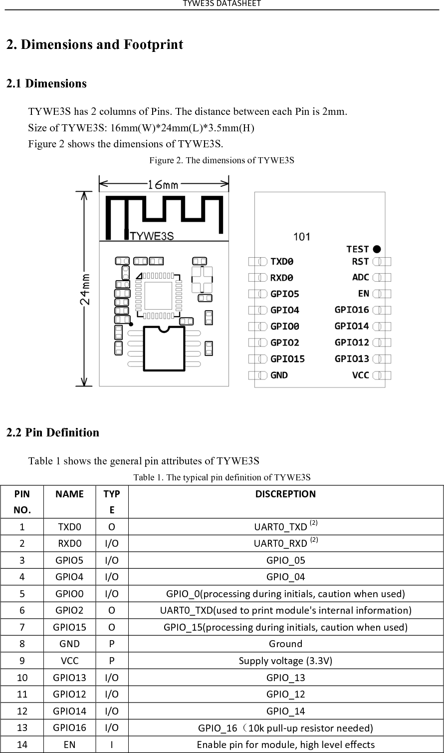
![!"#$%&'()!)&*$$!'+9')(U')5')(U'F?<MABGH2+-Z[AF@'&)0')(U4'2+4'+L'0&!'56.'$\F?<BGH'<?@?F'2H=J'H?W?H'?OO?>F@I'FK?<?N@'GH<?GDV'KGD';EHHZE;'<?@A@F=<4''Note: S: Power supply pins; I/O: Digital input or output pins; AI: Analog input. RST pin is the module hardware reset pin; it cannot eliminate module-pairing information. (*1) This pin can only be used as ADC input, cannot use it as normal I/O. when not using, just connect nothing. When used as ADC input, the input voltage range is 0~1.0V. (*2) UART0 is serial port, during power on progress; this serial port will output something, which can be ignored. 2.3 Test Pin Definition Table 2 shows the general test pin definition of TYWE3S Table 2. The general test pin definition of TYWE3S PIN$NO.$NAME$TYPE$DESCRIPTION$Z'!$&!'5'/@?D'O=<'M=DEH?]@';<=DE>FA=B'F?@F'Note: This test pin is not recommended to use.](https://usermanual.wiki/Hangzhou-AiXiangJi-Technology/TYWE3S.Users-Manual/User-Guide-3525098-Page-4.png)