Hangzhou AiXiangJi Technology TYWE3S WiFi Module User Manual TYWE3S EN V1x
Hangzhou AiXiangJi Technology Co., Ltd. WiFi Module TYWE3S EN V1x
Contents
- 1. Users Manual
- 2. User Manual
Users Manual
!"#$%&'()!)&*$$!'
TUYA WiFi Module
1. Product Overview
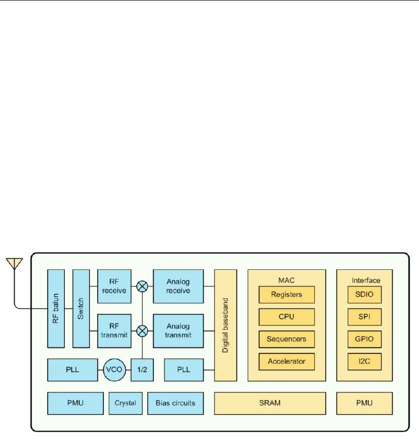
TYWE3S is a low power consumption module with built-in Wi-Fi connectivity solution
designed by HangZhou Tuya Technology Corporation. The Wi-Fi Module consists of a highly
integrated wireless radio chip ESP8266 and some extra component that has been programed with
Wi-Fi network protocol and plenty of software examples. TYWE3S include a 32-bit CPU, 1M
byte flash, 50k SRAM and various peripheral resources.
TYWE3S is a RTOS platform, embedded with all the Wi-Fi MAC and TCP/IP protocol
function examples, users can customize their Wi-Fi product by using these software examples.
Figure 1 shows the block diagram of the TYWE3S.
Figure 1. The block diagram of the TYWE3S
'
1.1 Features
² Integrated low power consumption 32-bit CPU, also known as application processor
² Basic frequency of the CPU can support both 80MHz and 160MHz
² Supply voltage range: 3V to 3.6V
² Peripherals: 9 GPIO channels, 1 UART, 1 ADC
² Wi-Fi connectivity:
l 802.11 b/g/n
l channel 1 to 11@2.4G for FCC,channel 1 to 13 @2.4G for EU
l Support WPA/WPA2
l +20dBm output power in 802.11b mode
l Support STA/AP/STA+AP operation mode
l Support SmartConfig function for both Android and IOS devices
l On-board PCB antenna
l Operating temperature range: -20℃ to 85℃

!"#$%&'()!)&*$$!'
1.2 Main Application Fields
² Intelligent Building
² Intelligent home, Intelligent household applications
² Health care
² Industrial wireless control
² Baby monitor
² Webcam
² Intelligent bus
'
'
!"#$%&'()!)&*$$!'
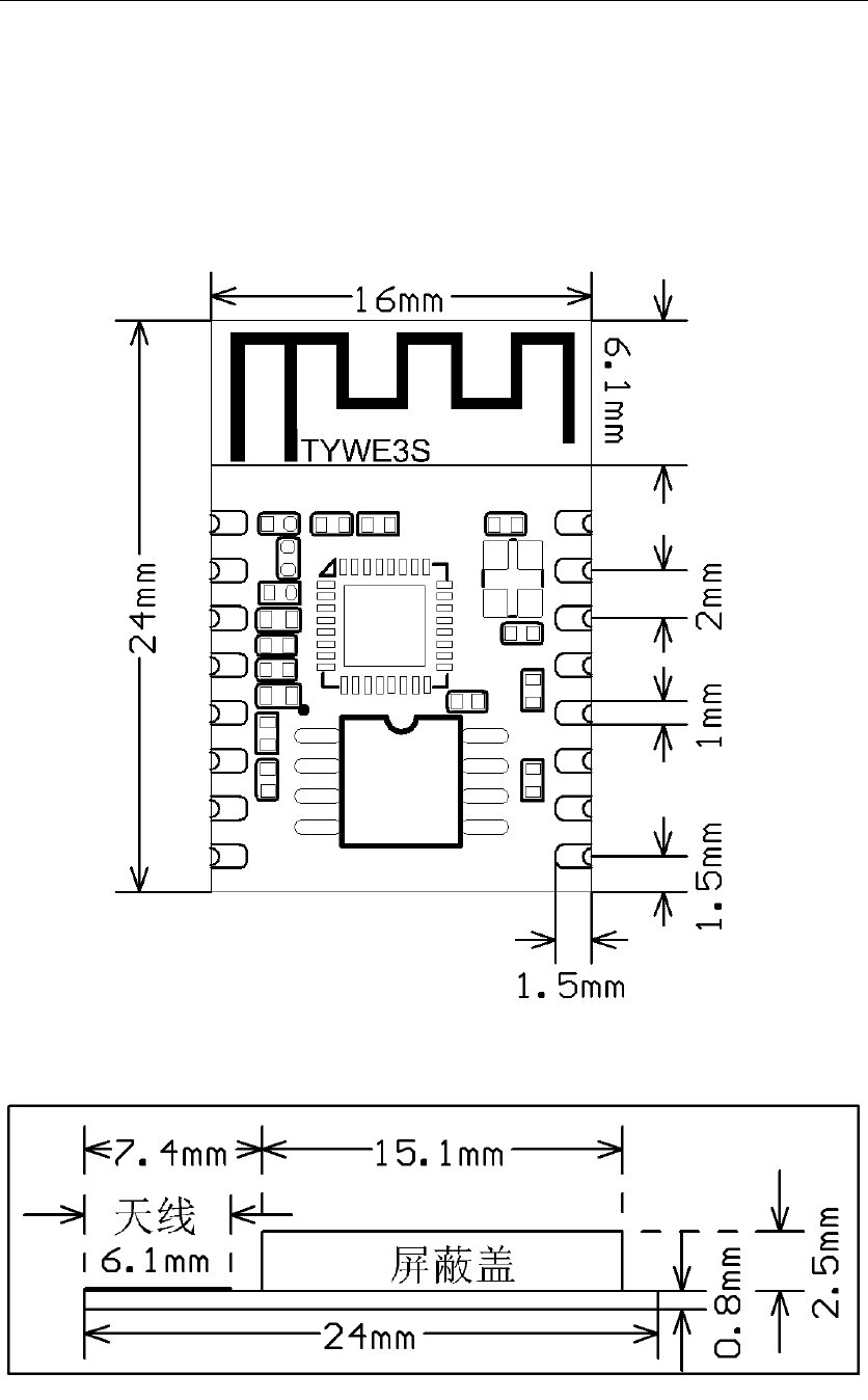
2. Dimensions and Footprint
2.1 Dimensions
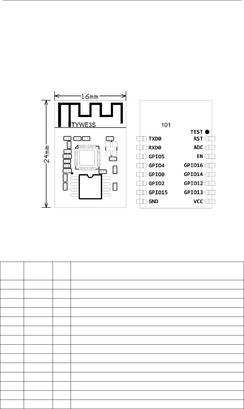
TYWE3S has 2 columns of Pins. The distance between each Pin is 2mm.
Size of TYWE3S: 16mm(W)*24mm(L)*3.5mm(H)
Figure 2 shows the dimensions of TYWE3S.
Figure 2. The dimensions of TYWE3S
'
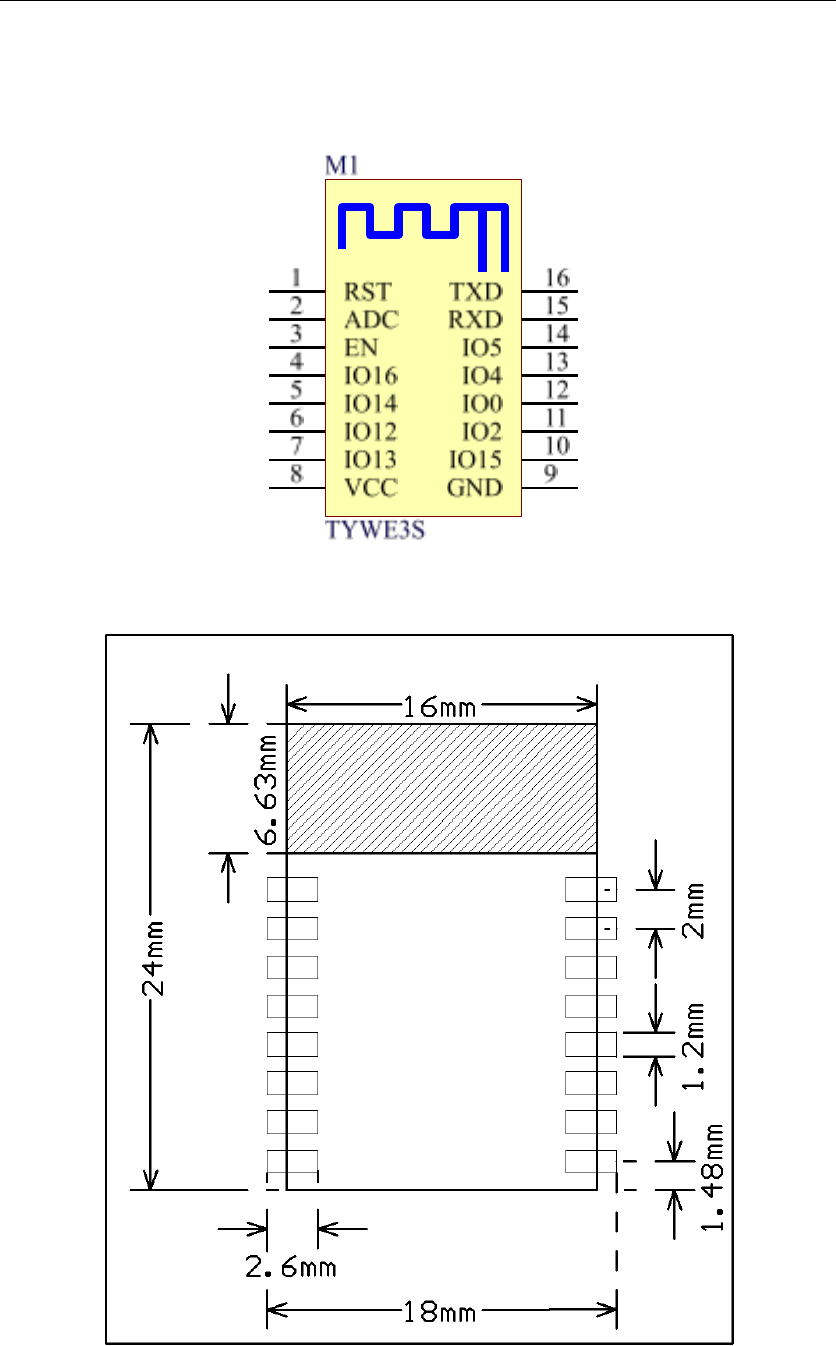
2.2 Pin Definition
Table 1 shows the general pin attributes of TYWE3S
Table 1. The typical pin definition of TYWE3S
PIN$
NO.$
NAME$
TYP
E$
DISCREPTION$
+'
!,(-'
.'
/)0!-1!,('234'
3'
0,(-'
56.'
/)0!-10,('234'
%'
785.9'
56.'
785.1-9'
:'
785.:'
56.'
785.1-:'
9'
785.-'
56.'
785.1-2;<=>?@@ABC'DE<ABC'ABAFAGH@I'>GEFA=B'JK?B'E@?D4'
L'
785.3'
.'
/)0!-1!,(2E@?D'F=';<ABF'M=DEH?N@'ABF?<BGH'ABO=<MGFA=B4'
P'
785.+9'
.'
785.1+92;<=>?@@ABC'DE<ABC'ABAFAGH@I'>GEFA=B'JK?B'E@?D4'
Q'
7R('
8'
7<=EBD'
S'
TUU'
8'
&E;;HV'W=HFGC?'2%X%T4'
+-'
785.+%'
56.'
785.1+%'
++'
785.+3'
56.'
785.1+3'
+3'
785.+:'
56.'
785.1+:'
+%'
785.+L'
56.'
785.1+L(+-Y';EHHZE;'<?@A@F=<'B??D?D4'
+:'
$R'
5'
$BG[H?';AB'O=<'M=DEH?I'KACK'H?W?H'?OO?>F@'
!"#$%&'()!)&*$$!'
+9'
)(U'
)5'
)(U'F?<MABGH2+-Z[AF@'&)0')(U4'2+4'
+L'
0&!'
56.'
$\F?<BGH'<?@?F'2H=J'H?W?H'?OO?>F@I'FK?<?N@'GH<?GDV'KGD';EHHZE;'<?@A@F=<4'
'
Note: S: Power supply pins; I/O: Digital input or output pins; AI: Analog input. RST pin is
the module hardware reset pin; it cannot eliminate module-pairing information.
(*1) This pin can only be used as ADC input, cannot use it as normal I/O. when not using,
just connect nothing. When used as ADC input, the input voltage range is 0~1.0V.
(*2) UART0 is serial port, during power on progress; this serial port will output something,
which can be ignored.
2.3 Test Pin Definition
Table 2 shows the general test pin definition of TYWE3S
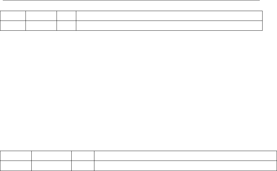
Table 2. The general test pin definition of TYWE3S
PIN$NO.$
NAME$
TYPE$
DESCRIPTION$
Z'
!$&!'
5'
/@?D'O=<'M=DEH?]@';<=DE>FA=B'F?@F'
Note: This test pin is not recommended to use.
!"#$%&'()!)&*$$!'
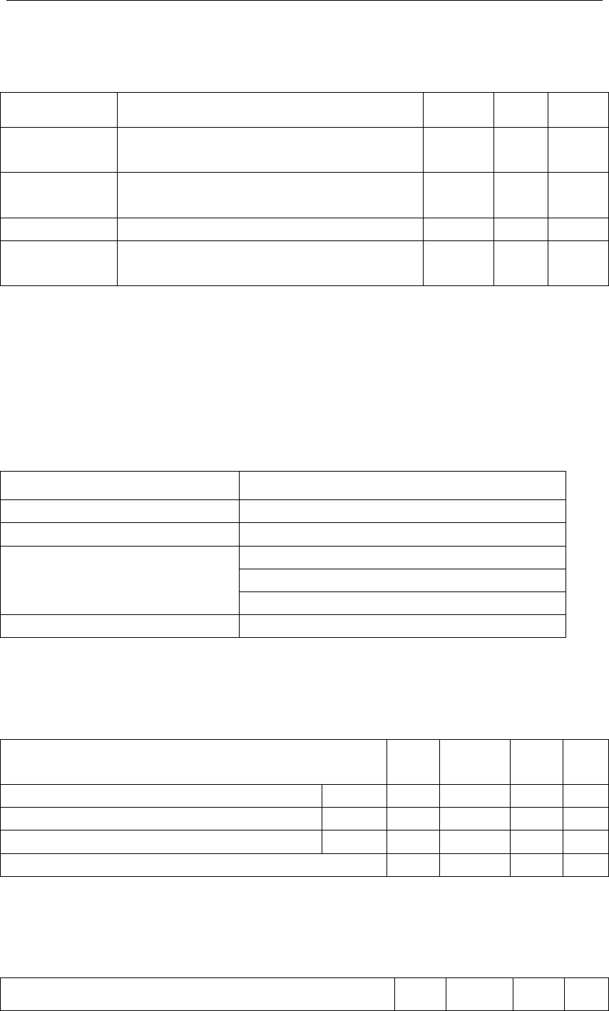
3. Electrical Characteristics
3.1 Absolute Maximum Ratings
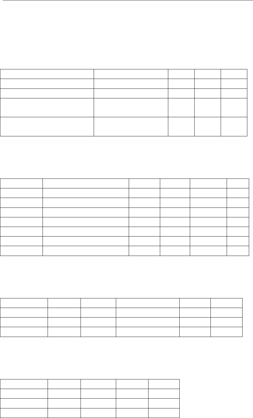
Table 3. Absolute Maximum Ratings
PARAMETERS$
DESCRIPTION$
MIN$
MAX$
UNIT$
!@'
&F=<GC?'F?M;?<GFE<?'
Z3-'
Q9'
℃'
TUU'
&E;;HV'W=HFGC?'
Z-X%'
%XL'
T'
&FGFA>'?H?>F<A>AFV'W=HFGC?' '
2KEMGB'M=D?H4'
!)^_Z39℃'
Z'
3'
`T'
&FGFA>'?H?>F<A>AFV'W=HFGC?'
'2MG>KAB?'M=D?H4'
!)^_Z39℃'
Z'
-X9'
`T'
'
3.2 Electrical Conditions
Table 4. Electrical Conditions
PARAMETERS$
DESCRIPTION$
MIN$
TYPICAL$
MAX$
UNIT$
!G'
#=<YABC'F?M;?<GFE<?'
Z3-'
Z'
Q9'
℃'
TUU'
#=<YABC'W=HFGC?'
%'
%X%'
%XL'
T'
T5a'
5.'H=J'H?W?H'AB;EF'
Z-X%'
Z'
TUUb-X39'
T'
T5*'
5.'KACK'H?W?H'AB;EF'
TUUb-XP9'
Z'
TUU'
T'
T.a'
5.'H=J'H?W?H'=EF;EF'
Z'
Z'
TUUb-X+'
T'
T=*'
5.'KACK'H?W?H'=EF;EF'
TUUb-XQ'
Z'
TUU'
T'
5MG\'
5.'D<AW?'>E<<?BF'
Z'
Z'
+3'
M)'
'
3.3 Wi-Fi Transmitting Current Consumptions
Table 5. Wi-Fi TX current consumption
8)0)^$!$0&'
^.($'
0)!$'
F<GB@MAFFABC';=J?<'
!"85U)a'
/R5!'
50c'
++['
++^[;@'
d+PD_M'
33-'
M)'
50c'
++C'
9:^[;@'
d+9D_M'
++-'
M)'
50c'
++B'
^U&P'
d+%D_M'
+--'
M)'
'
3.4 Wi-Fi Receiving Current Consumptions
Table 6. Wi-Fi RX current consumption
PARAMETERS$
MODE$
RATE$
TYPICAL$
UNIT$
50c'
++['
++^[;@'
PL'
M)'
50c'
++C'
9:^[;@'
PL'
M)'
50c'
++B'
^U&P'
PL'
M)'
'
!"#$%&'()!)&*$$!'
3.5 Working Mode Current Consumptions
Table 7. The module working current consumption
WORK$MODE$
AT$TA=25℃$
TYPICAL$
MAX*$
UNIT$
$e'^=D?'
!"#$%&'A@'EBD?<'$e';G<ABC'M=D?I'#AZcA'
ABDA>GF=<'HACKF'OHG@K?@'fEA>YHV'
Q-'
+9+'
M)'
)8'^=D?'
!"#$%&'A@'EBD?<')8';G<ABC'M=D?I'#AZcA'
ABDA>GF=<'HACKF'OHG@K?@'@H=JHV'
S-'
:9+'
M)'
.;?<GFA=B'^=D?'
!"#$%&'A@'>=BB?>F?DI'#AZcA'ABDA>GF=<'HACKF'A@'=B'
9QX9'
:++'
M)'
(A@>=BB?>FA=B'
^=D?'
!"#$%&'A@'DA@>=BB?>F?DI'#AZcA'ABDA>GF=<'HACKF'A@'
=OO'
Q-'
:%-'
M)'
4. WLAN Radio Specification
4.1 Basic Radio Frequency Characteristics
Table 8. Basic Radio frequency characteristics
PARAMETERS$
DESCRIPTION$
c<?fE?B>V'[GBD'
3X:7*g'F='3X97*g'
#AZcA'@FGBDG<D'
5$$$'Q-3X++B6C6['2!?<MABGH'+Z+:4'
(GFG'F<GB@MAFFABC'<GF?'
++[h+I3I9X9I++2^[;@4'
++ChLISI+3I+QI3:I%LI:QI9:2^[;@4'
++Bh*!3-I'^U&-iP'
)BF?BBG'FV;?'
.BZ[=G<D'8U_')BF?BBG' '
'
4.2 Wi-Fi Transmitting Power
Table 9. Wi-Fi transmitting power
PARAMETERS$
MIN$
TYPICAL$
MAX$
UNI
T$
0c'GW?<GC?'=EF;EF';=J?<I'Q-3X++['UU`'^=D?'
++^'
Z'
3-'
Z'
D_M'
0c'GW?<GC?'=EF;EF';=J?<I'Q-3X++C'.c(^'^=D?'
9:^'
Z'
+P'
Z'
D_M'
0c'GW?<GC?'=EF;EF';=J?<I'Q-3X++B'.c(^'^=D?'
^U&P'
Z'
+:'
Z'
D_M'
!K?'c<?fE?B>V'?<<=<'
Z+-'
Z'
+-'
;;M'
'
4.3 Wi-Fi Receiving Sensitivity
Table 9. Wi-Fi Receiving sensitivity
PARAMETERS$
MIN$
TYPICAL$
MAX$
UNI

!"#$%&'()!)&*$$!'
T$
8$0jQkI'0?>?AWABC'@?B@AFAWAFVI'Q-3X++['UU`'^=D?'
++^'
Z'
ZS+'
Z'
D_M'
8$0j+-kI'0?>?AWABC'@?B@AFAWAFVI'Q-3X++C'.c(^'^=D?'
9:^'
Z'
ZP9'
Z'
D_M'
8$0j+-kI'0?>?AWABC'@?B@AFAWAFVI'Q-3X++B'.c(^'^=D?'
^U&P'
Z'
ZP3'
Z'
D_M'
'
'

!"#$%&'()!)&*$$!'
5. Antenna Information
5.1 Antenna Type
Antenna can be connected only using On-board PCB antenna.
5.2 Reduce Antenna Interference
While using the On-board PCB antenna, in order to have the best Wi-Fi performance, it’s
recommended to keep a minimum 15mm distance between the antenna part and the other metal
pieces.
User’s own PCBA design is recommended NOT to pass any wire, NOT do copper pour under
the region of the module’s antenna, to avoid interferences.
!"#$%&'()!)&*$$!'
6. Packaging Information And Production Guide
6.1 Mechanical Dimensions
Figure 3. Top view of the module
'
'
Figure 4. The module’s mechanical view
'
!"#$%&'()!)&*$$!'
6.2 PCB Recommended Package
Figure 5. PCB schematic Drawing
' '
Figure 6. PCB Package Drawing
'
'
!"#$%&'()!)&*$$!'
6.3 Production Guide
² The storage for the delivered module should meet the following condition:
1. The anti-moisture bag should be kept in the environment with temperature < 30℃ and
humidity < 85% RH.
2. The expiration date is 6 months since the dry packaging products was sealed.
² Cautions:
1. All the operators should wear electrostatic ring in the whole process of production.
2. While operating, water and dirt should not have any contact with the modules.
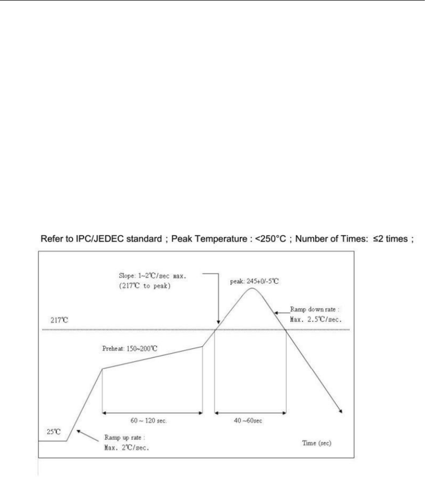
6.4 Recommended furnace temperature curve
Figure 7. PCB Package Drawing'Recommended furnace temperature curve
'
7. Declaration
7.1 Federal Communications Commission (FCC) Declaration of Conformity
FCC Caution: Any changes or modifications not expressly
approved by the party responsible for compliance could void the user's
authority to operate this equipment.
This device complies with Part 15 of the FCC Rules.

!"#$%&'()!)&*$$!'
Operation is subject to the following two conditions: (1) This device may not
cause harmful interference, and (2) this device must accept any interference
received, including interference that may cause undesired operation.
This device and its antenna(s) must not be co-located or operating in conjunction
with any other antenna or transmitter.
15.105 Information to the user.
(b) For a Class B digital device or peripheral, the instructions furnished the
user shall include the following or similar statement, placed in a prominent
location in the text of the manual:
Note: This equipment has been tested and found to comply
with the limits for a Class B digital device, pursuant to part 15 of the FCC Rules.
These limits are designed to provide reasonable protection against harmful
interference in a residential installation. This equipment generates, uses and
can radiate radio frequency energy and, if not installed and used in
accordance with the instructions, may cause harmful interference to radio
communications. However, there is no guarantee that interference will not
occur in a particular installation. If this equipment does cause harmful
interference to radio or television reception, which can be determined by
turning the equipment off and on, the user is encouraged to try to correct the
interference by one or more of the following measures:
—Reorient or relocate the receiving antenna.
—Increase the separation between the equipment and receiver.
—Connect the equipment into an outlet on a circuit different from that to which
the receiver is connected.
—Consult the dealer or an experienced radio/TV technician for help.
This equipment complies with FCC radiation exposure limits set forth for an
uncont
rolled environment. This equipment should be installed and operated with
minimum
distance 20cm between the radiator and your body.
Radiation Exposure Statement:
This equipment complies with FCC radiation exposure limits set forth for an
uncontrolled environment.
This transmitter must not be co-located or operating in conjunction with any other
antenna or transmitter.
The availability of some specific channels and/or operational frequency bands
are country dependent and are firmware programmed at the factory to match
the intended destination.
The firmware setting is not accessible by the end user.
The final end product must be labelled in a visible area with the following:
“Contains Transmitter Module 2AFNL-TYWE3S”
!"#$%&'()!)&*$$!'
This radio module must not installed to co-locate and operating simultaneously
with
other radios in host system, additional testing and equipment authorization may
be
required to operating simultaneously with other radio.
This LMA does not have RF shielding and is tested and approved as standalone
configuration, additional evaluation may be required for any system integrated
this radio module.
This transmitter module is authorized only for use in device where the antenna
may be installed such that 20 cm may be maintained between the antenna and
users. The final end product must be labeled in a visible area with the following:
“Contains FCC ID: 2AFNL-TYWE3S”.
7.2 Declaration of Conformity European notice
Hereby, Hangzhou AiXiangJi Technology Co., Ltd declares that this Wifi module
product is in compliance with essential requirements and other relevant provisions
of Directive 2014/53/EC. A copy of the Declaration of conformity can be found at
http://www.tuya.com.
'
$R'%--'%3Q'T3X+X+'
$R'%-+':QSZ+'T3X+X+l'$R'%-+':QSZ+P'T%X+X+'
$R'L3%++h3--Q'
$R'L-S9-Z+h3--Ld)++h3--Sd)+h3-+-d)+3h3-++d)3h3-+%'
The OEM integrator has to be aware not to provide information to the end user
regarding how to install or remove this RF module in the user's manual of the end
product which integrates this module. The end user manual shall include all required
regulatory information /warming as shown in this manual