Hangzhou Great Star KK4000 Wi-Fi Bluetooth Dual One Module User Manual KK 4000 UserMaunal
Hangzhou Great Star Industrial Co., Ltd. Wi-Fi Bluetooth Dual One Module KK 4000 UserMaunal
User Manual
KK-4000 User Manual
1. Overview
KK-4000 is a single chip integrated with 2.4 GHz Wi-Fi and Bluetooth dual mode. Using
TSMC (TSMC) ultra low power consumption nanotechnology, it has the best power performance,
RF performance, stability, versatility and reliability. It is suitable for various applications and
different power consumption requirements.
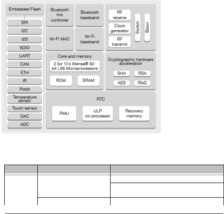
Table 1: The block diagram of the KK-4000
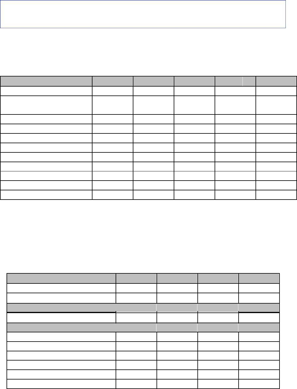
1.1 KK-4000 Specifications
Categories Items Specifications
IEEE 802.11b/g/n (802.11n up to 150 Mbps)
Wi-Fi Protocols A-MPDU and A-MSDU aggregation and 0.4 s guard
interval support
Frequency range 2.4GWi-Fi:2412-2462MHz(802.11b/g/n-HT20)
2422-2452MHz(802.11n-HT40)

Protocols Bluetooth v4.2 BR/EDR and BLE specification
NZIF receiver with -97 dBm sensitivity
Bluetooth Radio class-2 transmitter
AFH
Audio CVSD and SBC
Categories Items Specifications
SD card, UART, SPI, SDIO, I2C, LED PWM, Motor
Module interface PWM, I2S, IR
GPIO, capacitive touch sensor, ADC, DAC
On-chip sensor Hall sensor, temperature sensor
Hardware
Operating voltage/Power supply 2.7 ~ 3.6V
Operating current Average: 80 mA
Minimum current delivered by 500 mA
power supply
Operating temperature range -40°C ~ +85°C
Ambient temperature range Normal temperature
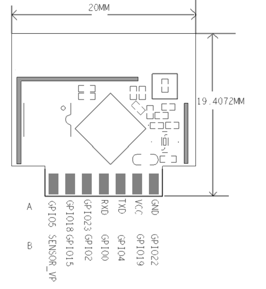
Package size 20 mm x 19.4mm x 3mm
1.2 application
universal low power IoT sensor Hub
general low power IoT recorder
Video streaming transmission of camera
OTT TV box / set-top box equipment
Music player - network music player - audio streaming media device
Wi-Fi toys - counter - Toy anti - loss devices
Wi-Fi speech recognition equipment
Ear wheat
Intelligent socket
family automation
Mesh network
Industrial wireless control
baby monitor
Wearable electronic products
2. PIN
DEFINITIONS
2.1 Dimensions
ESP32

2.2 Pin Description
KK-4000 has 14 pins. See pin definitions in Table 2.
Table 2: Pin Definitions
Name No. Function
GND_POWER A1 Power pipe foot, grounding
VDD_33 A2 Power pipe pin, 3.3V voltage input
UTXD A3 GPIO1、U0TXD、CLK_OUT3、EMAC_RXD2
URXD A4 GPIO3、U0RXD、CLK_OUT2
GPIO23 A5 GPIO23、VSPID、HS1_STROB
GPIO18 A6 GPIO18、VSPICLK、HS1_DATA7
GPIO5 A7 GPIO5、VSPICS0、HS1_DATA6、EMAC_RX_CL
GPIO22 B1 GPIO22、VSPIWP、U0RTS、EMAC_TXD1
GPIO19 B2 GPIO19、VSPIQ、U0CTS、EMAC_TXD
GPIO4 B3 GPIO4、ADC2_CH0、TOUCH0、RTC_GPIO10、HSPIHD、
HS2_DATA1、SD_DATA1、EMAC_TX_ER
GPIO0 B4 GPIO0、ADC2_CH1、TOUCH1、RTC_GPIO11、CLK_OUT1、
EMAC_TX_CLK
GPIO2 B5
GPIO2、ADC2_CH2、TOUCH2、RTC_GPIO12、HSPIWP、
HS2_DATA0、SD_DATA0
GPIO15 B6 General GPIO pin
SEBNSOR_VP B7 GPIO39、ADC1_CH3、ADC_PRE_AMP、RTC_GPIO3
3. Electrical Characteristics
Note:
The specifications in this chapter have been tested under the following general condition: VDD = 3.3V, TA = 27°C, unless
otherwise specified.
3.1 Absolute Maximum Ratings
Table 3: Absolute Maximum Ratings
Parameter Symbol Min Typ Max Unit
Power supply VDD 2.7 3.3 3.6 V
Minimum current delivered by IV DD 0.5 - - A
power supply
Input low voltage
V
IL -0.3 -
0.25×V
IO
1
V
Input high voltage
V
IH 0.75×VIO
1
-VIO
1
+0.3 V
Input leakage current
I
IL --50 nA
Input pin capacitance
C
pad - - 2 pF
Output low voltage
V
OL - - 1V
0.1×V
I
O
Output high voltage
V
OH 1- - V
0.8×V
I
O
Maximum output drive capability
I
MAX - - 40 mA
Storage temperature range
T
ST R -40 -85 °C
Operating temperature range
T
OP R -40 -85 °C
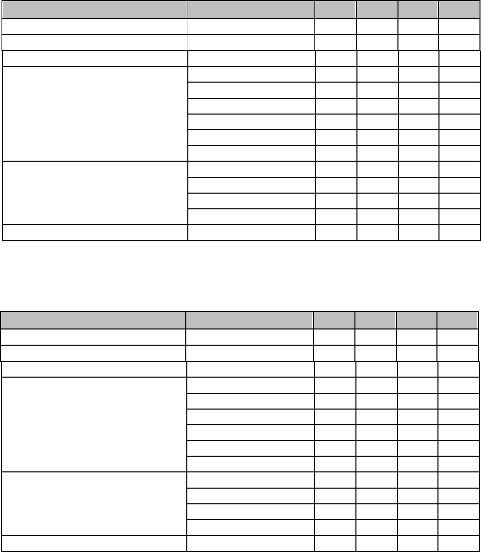
3.2 Wi-Fi Radio
Table 4: Wi-Fi Radio Characteristics
Description
Min Typical Max Unit
Input frequency
2412
-
2462
MHz
Input reflection
---10 dB
Tx power
Output power of PA for 11b mode 18.32 18.98 19.03 dBm
Sensitivity
DSSS, 1 Mbps --98 -dBm
CCK, 11 Mbps - -91 - dBm
OFDM, 6 Mbps - -93 - dBm
OFDM, 54 Mbps - -75 - dBm
HT20, MCS0 - -93 - dBm
HT20, MCS7 --73 -dBm

Description Min Typical Max Unit
HT40, MCS0 --90 -dBm
HT40, MCS7 - -70 - dBm
MCS32 - -89 - dBm
Adjacent channel rejection
OFDM, 6 Mbps - 37 - dB
OFDM, 54 Mbps - 21 - dB
HT20, MCS0 -37 -dB
HT20, MCS7 -20 -dB
3.3 BLE Radio
3.3.1 Receiver
Table 6: Receiver Characteristics — BLE
Parameter Conditions Min Typ Max Unit
Sensitivity @30.8% PER - - -97 - dBm
Maximum received signal @30.8% PER
- 0 - - dBm
Co-channel C/I - - +10 - dB
F = F0 + 1 MHz - -5 - dB
F = F0 - 1 MHz--5 - dB
Adjacent channel selectivity C/I F = F0 + 2 MHz --25 - dB
F = F0 - 2 MHz - -35 - dB
F = F0 + 3 MHz - -25 - dB
F = F0 - 3 MHz - -45 - dB
30 MHz ~ 2000 MHz -10 -- dBm
Out-of-band blocking performance 2000 MHz ~ 2400 MHz -27 - - dBm
2500 MHz ~ 3000 MHz -27 - - dBm
3000 MHz ~ 12.5 GHz -10 - - dBm
Intermodulation --36 - - dBm

3.3.2 Transmitter
Table 7: Transmitter Characteristics — BLE
Parameter Conditions Min Typ Max Unit
RF transmit power - - 0 - dBm
RF power control range - -1 - +1 dBm
Parameter Conditions Min Typ Max Unit
F = F0 + 1 MHz - -14.6 - dBm
F = F0 - 1 MHz - -12.7 - dBm
F = F0 + 2 MHz - -44.3 - dBm
Adjacent channel transmit power F = F0 - 2 MHz - -38.7 - dBm
F = F0 + 3 MHz --49.2 - dBm
F = F0 - 3 MHz - -44.7 - dBm
F = F0 + > 3 MHz - -50 - dBm
F = F0 - > 3 MHz - -50 - dBm
∆ f1avg - - - 265 kHz
∆ f2max - 247 - - kHz
∆ f2avg/∆ f1avg - - -0.92 - -
ICFT - - -10 - kHz
Drift rate - - 0.7 - kHz/50 s
Drift - - 2 - kHz
3.4 Bluetooth Radio
3.4.1 Receiver (BDR)
Table 7: Receiver Characteristics — BDR
Parameter Conditions Min Typ Max Unit
Sensitivity @0.1% PER - - -94 - dBm
Maximum received signal @30.8% PER
- 0 - - dBm
Co-channel C/I - - +17- dB
F = F0 + 1 MHz - - - 6dB
F = F0 - 1 MHz - - -6 dB
Adjacent channel selectivity C/I F = F0 + 2 MHz ---25 dB
F = F0 - 2 MHz - -- 33 dB
F = F0 + 3 MHz - --25 dB
F = F0 - 3 MHz - -- 45 dB
30 MHz ~ 2000 MHz -10 -- dBm
Out-of-band blocking performance 2000 MHz ~ 2400 MHz -27 - - dBm
2500 MHz ~ 3000 MHz -27 - - dBm
3000 MHz ~ 12.5 GHz -10 - - dBm
Intermodulation --36 - - dBm
Table 7: Receiver Characteristics — EDR(π/4 DPSK)
Parameter Conditions Min Typ Max Unit
Sensitivity @0.1% PER - - -90 - dBm
Maximum received signal @30.8% PER
- 0 0- dBm
Co-channel C/I - - +11- dB
F = F0 + 1 MHz - -7 - dB
F = F0 - 1 MHz - -7 -dB
Adjacent channel selectivity C/I F = F0 + 2 MHz --25 -dB
F = F0 - 2 MHz - -35 - dB
F = F0 + 3 MHz - -25 -dB
F = F0 - 3 MHz - -45 - dB
30 MHz ~ 2000 MHz --- dBm
Out-of-band blocking performance 2000 MHz ~ 2400 MHz -- - dBm
2500 MHz ~ 3000 MHz -- - dBm
3000 MHz ~ 12.5 GHz -- - dBm
Intermodulation --- - dBm
3.4.2 Receiver (EDR)
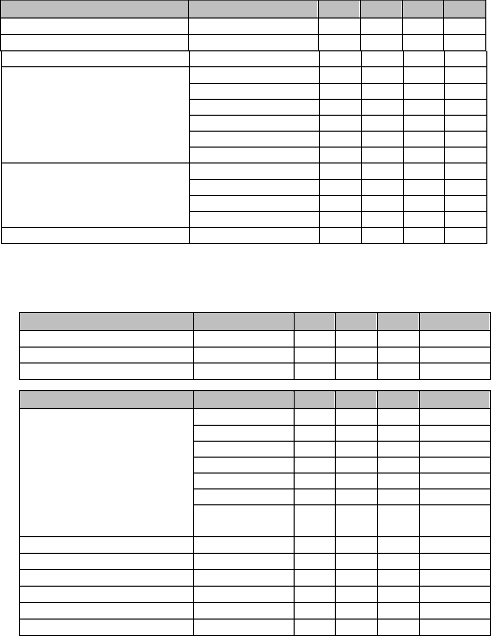
Table 8: Receiver Characteristics — EDR(8 DPSK)
Parameter Conditions Min Typ Max Unit
Sensitivity @0.1% PER - - -84 - dBm
Maximum received signal @30.8% PER
- 0 5- dBm
Co-channel C/I - - +18- dB
F = F0 + 1 MHz - 2- dB
F = F0 - 1 MHz -2-dB
Adjacent channel selectivity C/I F = F0 + 2 MHz --25 -dB
F = F0 - 2 MHz - -25 - dB
F = F0 + 3 MHz - -25 -dB
F = F0 - 3 MHz - -38 - dB
30 MHz ~ 2000 MHz --- dBm
Out-of-band blocking performance 2000 MHz ~ 2400 MHz -- - dBm
2500 MHz ~ 3000 MHz -- - dBm
3000 MHz ~ 12.5 GHz -- - dBm
Intermodulation --- - dBm
3.4.3 Transmitter
Table 9: Transmitter Characteristics — BDR
Parameter Conditions Min Typ Max Unit
RF transmit power - - -1.61 - dBm
RF power control range - -1.81 - -1.39 dBm
Parameter Conditions Min Typ Max Unit
F = F0 + 1 MHz - -24 - dBm
F = F0 - 1 MHz - -16.1 - dBm
F = F0 + 2 MHz - -40.8 - dBm
Adjacent channel transmit power F = F0 - 2 MHz - -35.6 - dBm
F = F0 + 3 MHz --45.7 - dBm
F = F0 - 3 MHz - -40.2 - dBm
45.6 - dBm F = F0 + > 3 MHz -
F = F0 - > 3 MHz - 45.6 - dBm
∆ f1avg - - - 155 kHz
∆ f2max - 133.7 - - kHz
∆ f2avg/∆ f1avg - - 0.92 - -
ICFT - - -7- kHz
Drift rate - - 0.7 - kHz/50 s
Drift - - 6 - kHz

Table 10: Transmitter Characteristics — EDR
Parameter Conditions Min Typ Max Unit
RF transmit power - - -0.02 - dBm
RF power control range - -0.48 - 0.49 dBm
Parameter Min Typ Max Unit
- -0.72 - kHz
- -6 - kHz
- -7.42 - kHz
- 0.7 - kHz
--9.6 - kHz
- -10 kHz
4.28 - %
-30 %
-13.3 -%
8DPSK modulation accuracy
- %
- 5.8
- - %
-14 - %
- -34 - dBm
In-band spurious emissions
- -40.2 - dBm
Gain controll step - - - - dBm
π/4 DQPSK max w0
π/4 DQPSK max wi
π/4 DQPSK max (wi+w0)
8DPSK max w0
8DPSK max wi
8DPSK max (wi+w0)
π/4 DQPSK modulation accuracy
--34 155 dBm
- dBm-
- 36
- -38 dBm
--40.3 - dBm
- -- 41.5 dBm
- 100 - %
EDR differential phase coding
20
RMS DEVM
99% DEVM
Peak DEVM
RMS DEVM
99% DEVM
Peak DEVM
F = F0 + 1MHz
F = F0 – 1MHz
F = F0 + 2MHz
F = F0 – 2MHz
F = F0 + 3MHz
F = F0 – 3MHz
F = F0 ± >3MHz
-
-
-
• 520 kB (8 kB RTC FAST Memory included) of on-chip SRAM for data and instruction.
– 8 kB of SRAM in RTC, which is called RTC FAST Memory and can be used for data storage; it is
accessed by the main CPU during RTC Boot from the Deep-sleep mode.
• 8 kB of SRAM in RTC, which is called RTC SLOW Memory and can be accessed by the co-processor
during the Deep-sleep mode.
• 1 kbit of eFuse, of which 320 bits are used for the system (MAC address and chip configuration) and
the remaining 704 bits are reserved for customer applications, including Flash-Encryption and Chip-ID.
4.2 External Flash and SRAM
KK-4000 supports up to four 16-MB of external QSPI flash and SRAM with hardware encryption based
on AES to protect developers’ programs and data.
KK-4000 can access the external QSPI flash and SRAM through high-speed caches.
• Up to 16 MB of external flash are memory-mapped onto the CPU code space, supporting 8, 16 and 32-
bit access. Code execution is supported.
• Up to 8 MB of external flash/SRAM are memory-mapped onto the CPU data space, supporting 8, 16 and 32-
KK-4000bit access. Data-read is supported on the flash and SRAM. Data-write is supported on the SRAM.
integrates 4 MB of external SPI flash. The 4-MB SPI flash can be memory-mapped onto the CPU code
space, supporting 8, 16 and 32-bit access. Code execution is supported.
4.3 Crystal Oscillators
The KK-4000 Wi-Fi/BT firmware can only support 40 MHz crystal oscillator for now.
4. Functional Description
This chapter describes the modules and functions integrated in KK-4000
4.1 CPU and Internal Memory
KK-4000 contains two low-power Xtensa® 32-bit LX6 microprocessors. The internal memory includes:
• 448 kB of ROM for booting and core functions.
FCC Statement
Any Changes or modifications not expressly approved by the party responsible for compliance could void the user’s
authority to operate the equipment.
This device complies with part 15 of the FCC Rules. Operation is subject to the following two conditions:
(1) This device may not cause harmful interference, and
(2) This device must accept any interference received, including interference that may cause undesired operation.
FCC Radiation Exposure Statement:
This equipment complies with FCC radiation exposure limits set forth for an uncontrolled environment .This equipment
should be installed and operated with minimum distance 20cm between the radiator& your body.
ISED RSS Warning/ISED RF Exposure Statement
ISED RSS Warning:
This device complies with Innovation, Science and Economic Development Canada licence-exempt RSS standard(s).
Operation is subject to the following two conditions: (1) this device may not cause interference, and (2) this device must
accept any interference, including interference that may cause undesired operation of the device.
Le présent appareil est conforme aux CNR d'ISED applicables aux appareils radio exempts de licence. L'exploitation est
autorisée aux deux conditions suivantes: (1) l'appareil ne doit pas produire de brouillage, et (2) l'utilisateur de l'appareil doit
accepter tout brouillage radioélectrique subi, même si le brouillage est susceptible d'en compromettre le fonctionnement.
ISED RF exposure statement:
This equipment complies with ISED radiation exposure limits set forth for an uncontrolled environment. This equipment
should be installed and operated with minimum distance 20cm between the radiator& your body.This transmitter must not be
co-located or operating in conjunction with any other antenna or transmitter.
Le rayonnement de la classe b repecte ISED fixaient un environnement non contrôlés.Installation et mise en œuvre de ce
matériel devrait avec échangeur distance minimale entre 20 cm ton corps.Lanceurs ou ne peuvent pas coexister cette antenne
ou capteurs avec d’autres.
FCC & ISED Label Instructions
The outside of final products that contains this module device must display a label referring to the enclosed module. This
exterior label can use wording such as: “Contains Transmitter Module FCC ID: 2AMI2-KK4000,IC:22853-KK4000" or
“Contains FCC ID: 2AMI2-KK4000,IC:22853-KK4000” Any similar wording that expresses the same meaning may be used.