Hangzhou Hikvision Digital Technology D0211506 Dual-tech Detector User Manual
Hangzhou Hikvision Digital Technology Co., Ltd. Dual-tech Detector Users Manual
User Manual
DS-PD2-D15E
15m DualͲƚech Detector
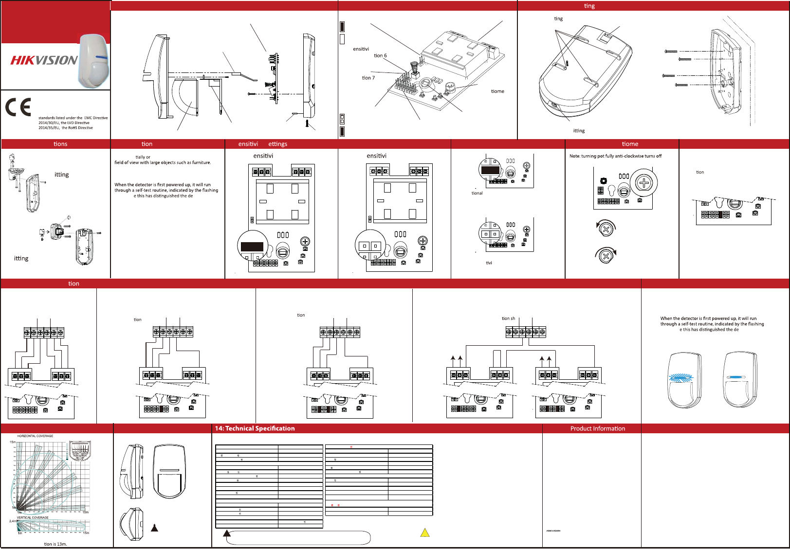
1: Disassembling the KX
4: Bracket Connec 6: S ty S 7: AND/OR Mode 8: Microwave Poten ter5: Installa Hints 9: EOL Resistor Headers
a) Auto S ty (Default)
b) Wall Bracket
F
a) Ceiling
Bracket
F
b) High S ty
ALARM CONTROL PANEL
+-
ZONE1
COM
TAM PER
TAM PER
+-
5K6
5K6
6K8
4K7
4K7
2K2
1K
1K
ALARM
TAM PER
TAM PERALM ALM
a) Normally Closed
ALARM CONTROL PANEL
+-
ZONE1
COM
TAM PER
TAM PER
+-
5K6
5K6
6K8
4K7
4K7
2K2
1K
1K
ALARM
TAM PE R
TAM PERALM ALM
b) Single End of Line Wiring
ALARM CONTROL PANEL
+-
ZONE1
COM
TAM PER
TAM PER
+-
Link
+-
+-
5K6
5K6
6K8
4K7
4K7
2K2
1K
1K
ALARM
TAM PE R
TAM PERALM ALM
+-
5K6
5K6
6K8
4K7
4K7
2K2
1K
1K
ALARM
TAM PE R
TAM PERALM ALM
5K6
5K6
6K8
4K7
4K7
2K2
1K
1K
ALARM
TAM PER
ALARM CONTROL PANEL
+-
ZONE1
COM
TAM PER
TAM PER
+-
5K6
5K6
6K8
4K7
4K7
2K2
1K
1K
ALARM
TAM PE R
TAM PERALM ALM
c) Double End of Line Wiring d) Two Double End of Line Detectors to One Input
15:
2: The Printed Circuit Board 3: Cable Entry + Moun
10: Choose the Connec Type: 11: Powering Up
12: The 15m Volumetric Lens 13: Dimensions and Weight
b) Lens Illuminator
a) Printed Circuit Board
d) Lens Holder
c) Lens
f) Back
Tamper
e) PCB
Screw
f) Nut
g) Casing Screw
h) Microwave
Poten ter
f) Tamper and Alarm
Resistor Headers
a) Terminals a) Moun Screw
Knockouts
b) Cable Entry
Knockout
c) Case Lid Screw
F
b) Mains Frequency
c) S ty Auto/High
See Sec
d) AND/OR
e) ALARM LED
See sec
50Hz
(Default)
LED Disable
60Hz
LED Enable
(Default)
g) Pyro Sensor
DO NOT TOUCH
The device has 2 set of header pin s at the top of
the printed circuit board. These headers are used
to select the End of Line resistance for EOL wiring
applica s.
If EOL wiring is not used, leave the headers OFF.
microwave
Conven Dual Tech (Both technologies need to
be triggered simultaneously to generate an alarm)
AND
OR
If either single technology detects prolonged
intruder ac ty an alarm will be generated
The connec ows
the example values
4k7 for alarm, 4k7 for
tamper (EOL).
The
connec
shows the
example value
4k7 for tamper
(EOL).
The
connec
shows the
example
values of 4k7
for Alarm and
4K7 for tamper
(EOL).
Avoiding False Alarms
117 x 69 x 50mm
125g (4.4 oz)
without bracket
LEDs. Onc tector is
ready to use.
1. Avoid placing the detector in direct sunlight.
2. Do not let pets and other animals wander freely
whilst the alarm system is armed.
3. Do not mount the detector near heaters or
radiators.
4. Do not mount the detector near open windows or
Do not par completely obscure the detector’s
C
5
Minimum
Range (0m)
Maximum
Range (15m)
85°
60 zones
7 planes
RLNS074
* In an EN50131-1 (and INCERT) system the
maximum detec
LEDs. Onc tector is
ready to use.
NOT READY READY 9
8
®
This product operates in a European non-harmonised
frequency band
!
This product and - if applicable - the
supplied accessories too are marked with
"CE" and comply therefore with the
applicable harmonized European
2011/65/EU.
DetectorDetectorDetector
Detector Detector
Coverage 85°, 60zones, 7planes
Maximum range 15m
Op mal installa on height 1.8- 2.4m
Creep-zone protec on yes
Blue Wave Technology yes
Automa c sensi vity yes
Digital temperature compensa on yes
Separate indica on: microwave, PIR and alarm yes
3 microwave frequencies to avoid interference yes
DEOL resistors on board yes
Tampe r protec on included yes
Signal Strength Indicators (SSI) n/a
Power supply 9-16 DC (12DC nominal)
Current consump on at rest 23mA
Current consump on i n alarm 30mA
Relay type Solid state
Output re lay 60DC, 50mA pro te c on
Tamper terminal 12DC max, 50mA max
Key fe atures
Wired
Microwave frequency 10.515, 10.525, 10.535GHz
Al arm re spon se 2.5 second
Dete c on speed 0.3 - 3m/s
Direct light Įlter 6500 Lux
Op cs Sealed
Geometric lens conĮgura on 3D
Opera ng tempe rature -10°C / +40°C
Weight 125g
Dimensions 117 x 69 x 5Ϭmm
Accessories
Wall/ceiling brackets included yes
Electrical conformity CE
Warranty 2 years
Electrical speciĮca ons
Other details
Cer Įca ons and warranty
&/ŶĨŽƌŵĂƟŽŶ
WůĞĂƐĞƚĂŬĞĂƩĞŶƟŽŶƚŚĂƚĐŚĂŶŐĞƐŽƌŵŽĚŝĮĐĂƟŽŶŶŽƚĞdžƉƌĞƐƐůLJĂƉƉƌŽǀĞĚďLJ
the party responsible for compliance could void the user’s authority to operate
the equipment.
FCC compliance: This equipment has been tested and found to comply with the
limits for a Class B digital device, pursuant to part 15 of the FCC Rules. These
ůŝŵŝƚƐĂƌĞĚĞƐŝŐŶĞĚƚŽƉƌŽǀŝĚĞƌĞĂƐŽŶĂďůĞƉƌŽƚĞĐƟŽŶĂŐĂŝŶƐƚŚĂƌŵĨƵůŝŶƚĞƌĨĞƌĞŶĐĞ
ŝŶĂƌĞƐŝĚĞŶƟĂůŝŶƐƚĂůůĂƟŽŶ͘dŚŝƐĞƋƵŝƉŵĞŶƚŐĞŶĞƌĂƚĞƐ͕ƵƐĞƐĂŶĚĐĂŶƌĂĚŝĂƚĞƌĂĚŝŽ
frequency energy and, if not installed and used in accordance with the
ŝŶƐƚƌƵĐƟŽŶƐ͕ŵĂLJĐĂƵƐĞŚĂƌŵĨƵůŝŶƚĞƌĨĞƌĞŶĐĞƚŽƌĂĚŝŽĐŽŵŵƵŶŝĐĂƟŽŶƐ͘,ŽǁĞǀĞƌ͕
ƚŚĞƌĞŝƐŶŽŐƵĂƌĂŶƚĞĞƚŚĂƚŝŶƚĞƌĨĞƌĞŶĐĞǁŝůůŶŽƚŽĐĐƵƌŝŶĂƉĂƌƟĐƵůĂƌŝŶƐƚĂůůĂƟŽŶ͘/Ĩ
ƚŚŝƐĞƋƵŝƉŵĞŶƚĚŽĞƐĐĂƵƐĞŚĂƌŵĨƵůŝŶƚĞƌĨĞƌĞŶĐĞƚŽƌĂĚŝŽŽƌƚĞůĞǀŝƐŝŽŶƌĞĐĞƉƟŽŶ͕
ǁŚŝĐŚĐĂŶďĞĚĞƚĞƌŵŝŶĞĚďLJƚƵƌŶŝŶŐƚŚĞĞƋƵŝƉŵĞŶƚŽīĂŶĚŽŶ͕ƚŚĞƵƐĞƌŝƐ
encouraged to try to correct the interference by one or more of the following
measures:
—Reorient or relocate the receiving antenna.
Ͷ/ŶĐƌĞĂƐĞƚŚĞƐĞƉĂƌĂƟŽŶďĞƚǁĞĞŶƚŚĞĞƋƵŝƉŵĞŶƚĂŶĚƌĞĐĞŝǀĞƌ͘
ͶŽŶŶĞĐƚƚŚĞĞƋƵŝƉŵĞŶƚŝŶƚŽĂŶŽƵƚůĞƚŽŶĂĐŝƌĐƵŝƚĚŝīĞƌĞŶƚĨƌŽŵƚŚĂƚƚŽǁŚŝĐŚ
the receiver is connected.
—Consult the dealer or an experienced radio/TV technician for help
&ŽŶĚŝƟŽŶƐ
dŚŝƐĚĞǀŝĐĞĐŽŵƉůŝĞƐǁŝƚŚƉĂƌƚϭϱŽĨƚŚĞ&ZƵůĞƐ͘KƉĞƌĂƟŽŶŝƐƐƵďũĞĐƚƚŽƚŚĞ
ĨŽůůŽǁŝŶŐƚǁŽĐŽŶĚŝƟŽŶƐ͗
1. This device may not cause harmful interference.
2. This device must accept any interference received, including interference that
ŵĂLJĐĂƵƐĞƵŶĚĞƐŝƌĞĚŽƉĞƌĂƟŽŶ͘
User Manual
COPYRIGHT ©2018 Hangzhou Hikvision Digital Technology Co., Ltd.
ALL RIGHTS RESERVED.
ŶLJĂŶĚĂůůŝŶĨŽƌŵĂƟŽŶ͕ŝŶĐůƵĚŝŶŐ͕ĂŵŽŶŐŽƚŚĞƌƐ͕ǁŽƌĚŝŶŐƐ͕
ƉŝĐƚƵƌĞƐ͕ŐƌĂƉŚƐĂƌĞƚŚĞƉƌŽƉĞƌƟĞƐŽĨ,ĂŶŐnjŚŽƵ,ŝŬǀŝƐŝŽŶŝŐŝƚĂů
dĞĐŚŶŽůŽŐLJŽ͕͘>ƚĚ͘ŽƌŝƚƐƐƵďƐŝĚŝĂƌŝĞƐ;ŚĞƌĞŝŶĂŌĞƌƌĞĨĞƌƌĞĚƚŽďĞ
͞,ŝŬǀŝƐŝŽŶ͟Ϳ͘dŚŝƐƵƐĞƌŵĂŶƵĂů;ŚĞƌĞŝŶĂŌĞƌƌĞĨĞƌƌĞĚƚŽďĞ͞ƚŚĞ
Manual”) cannot be reproduced, changed, translated, or
ĚŝƐƚƌŝďƵƚĞĚ͕ƉĂƌƟĂůůLJŽƌǁŚŽůůLJ͕ďLJĂŶLJŵĞĂŶƐ͕ǁŝƚŚŽƵƚƚŚĞƉƌŝŽƌ
ǁƌŝƩĞŶƉĞƌŵŝƐƐŝŽŶŽĨ,ŝŬǀŝƐŝŽŶ͘hŶůĞƐƐŽƚŚĞƌǁŝƐĞƐƟƉƵůĂƚĞĚ͕
,ŝŬǀŝƐŝŽŶĚŽĞƐŶŽƚŵĂŬĞĂŶLJǁĂƌƌĂŶƟĞƐ͕ŐƵĂƌĂŶƚĞĞƐŽƌ
ƌĞƉƌĞƐĞŶƚĂƟŽŶƐ͕ĞdžƉƌĞƐƐŽƌŝŵƉůŝĞĚ͕ƌĞŐĂƌĚŝŶŐƚŽƚŚĞDĂŶƵĂů͘
About this Manual
This manual is applicable to detector.
dŚĞDĂŶƵĂůŝŶĐůƵĚĞƐŝŶƐƚƌƵĐƟŽŶƐĨŽƌƵƐŝŶŐĂŶĚŵĂŶĂŐŝŶŐƚŚĞ
ƉƌŽĚƵĐƚ͘WŝĐƚƵƌĞƐ͕ĐŚĂƌƚƐ͕ŝŵĂŐĞƐĂŶĚĂůůŽƚŚĞƌŝŶĨŽƌŵĂƟŽŶ
ŚĞƌĞŝŶĂŌĞƌĂƌĞĨŽƌĚĞƐĐƌŝƉƟŽŶĂŶĚĞdžƉůĂŶĂƟŽŶŽŶůLJ͘dŚĞ
ŝŶĨŽƌŵĂƟŽŶĐŽŶƚĂŝŶĞĚŝŶƚŚĞDĂŶƵĂůŝƐƐƵďũĞĐƚƚŽĐŚĂŶŐĞ͕ǁŝƚŚŽƵƚ
ŶŽƟĐĞ͕ĚƵĞƚŽĮƌŵǁĂƌĞƵƉĚĂƚĞƐŽƌŽƚŚĞƌƌĞĂƐŽŶƐ͘WůĞĂƐĞĮŶĚƚŚĞ
latest version in the company website
;ŚƩƉ͗ͬͬŽǀĞƌƐĞĂƐ͘ŚŝŬǀŝƐŝŽŶ͘ĐŽŵͬĞŶͬͿ͘
Please use this user manual under the guidance of professionals.
Trademarks Acknowledgement
and other Hikvision’s trademarks and logos are the
ƉƌŽƉĞƌƟĞƐŽĨ,ŝŬǀŝƐŝŽŶŝŶǀĂƌŝŽƵƐũƵƌŝƐĚŝĐƟŽŶƐ͘KƚŚĞƌƚƌĂĚĞŵĂƌŬƐ
ĂŶĚůŽŐŽƐŵĞŶƟŽŶĞĚďĞůŽǁĂƌĞƚŚĞƉƌŽƉĞƌƟĞƐŽĨƚŚĞŝƌƌĞƐƉĞĐƟǀĞ
owners.
The Input voltage should meet both the SELV (Safety Extra Low Voltage) and the Limited Power Source according
to the IEC60950-1 standard. Please refer to technical specifications for detailed information.
!