Hangzhou Hikvision Digital Technology H2TR03 Thermal Telescope User Manual
Hangzhou Hikvision Digital Technology Co., Ltd. Thermal Telescope Users Manual
Users Manual

Thermal Scope
User Manual
.
UD11400B
0504001080820
COPYRIGHT © 2018 Hikvision. ALL RIGHTS RESERVED

About This Manual
COPYRIGHT ©2018 Hangzhou Hikvision Digital Technology
Co., Ltd.
ALL RIGHTS RESERVED.
Any and all information, including, among others, wordings, pictures,
graphs are the properties of Hangzhou Hikvision Digital Technology
Co., Ltd. or its subsidiaries (hereinafter referred to be “Hikvision”).
This user manual (hereinafter referred to be “the Manual”) cannot be
reproduced, changed, translated, or distributed, partially or wholly,
by any means, without the prior written permission of Hikvision.
Unless otherwise stipulated, Hikvision does not make any warranties,
guarantees or representations, express or implied, regarding to the
Manual.
This Manual is applicable to Handheld Thermal scope.
The Manual includes instructions for using and managing the product.
Pictures, charts, images and all other information hereinafter are for
description and explanation only. The information contained in the
Manual is subject to change, without notice, due to firmware updates
or other reasons. Please find the latest version in the company
website (http://overseas.hikvision.com/en/).
Please use this user manual under the guidance of professionals.
Trademarks Acknowledgement
and other Hikvision’s trademarks and logos are the
properties of Hikvision in various jurisdictions. Other trademarks and
logos mentioned below are the properties of their respective owners.
Legal Disclaimer
TO THE MAXIMUM EXTENT PERMITTED BY APPLICABLE
LAW, THE PRODUCT DESCRIBED, WITH ITS HARDWARE,
SOFTWARE AND FIRMWARE, IS PROVIDED “AS IS”, WITH
ALL FAULTS AND ERRORS, AND HIKVISION MAKES NO
WARRANTIES, EXPRESS OR IMPLIED, INCLUDING
WITHOUT LIMITATION, MERCHANTABILITY,
SATISFACTORY QUALITY, FITNESS FOR A PARTICULAR
PURPOSE, AND NON-INFRINGEMENT OF THIRD PARTY. IN
NO EVENT WILL HIKVISION, ITS DIRECTORS, OFFICERS,
EMPLOYEES, OR AGENTS BE LIABLE TO YOU FOR ANY
SPECIAL, CONSEQUENTIAL, INCIDENTAL, OR INDIRECT
DAMAGES, INCLUDING, AMONG OTHERS, DAMAGES FOR
LOSS OF BUSINESS PROFITS, BUSINESS INTERRUPTION, OR
LOSS OF DATA OR DOCUMENTATION, IN CONNECTION
WITH THE USE OF THIS PRODUCT, EVEN IF HIKVISION HAS
BEEN ADVISED OF THE POSSIBILITY OF SUCH DAMAGES.
REGARDING TO THE PRODUCT WITH INTERNET ACCESS,
THE USE OF PRODUCT SHALL BE WHOLLY AT YOUR OWN
RISKS. HIKVISION SHALL NOT TAKE ANY
RESPONSIBILITES FOR ABNORMAL OPERATION, PRIVACY
LEAKAGE OR OTHER DAMAGES RESULTING FROM CYBER
ATTACK, HACKER ATTACK, VIRUS INSPECTION, OR
OTHER INTERNET SECURITY RISKS; HOWEVER, HIKVISION
WILL PROVIDE TIMELY TECHNICAL SUPPORT IF
REQUIRED.
SURVEILLANCE LAWS VARY BY JURISDICTION. PLEASE
CHECK ALL RELEVANT LAWS IN YOUR JURISDICTION
BEFORE USING THIS PRODUCT IN ORDER TO ENSURE
THAT YOUR USE CONFORMS THE APPLICABLE LAW.
HIKVISION SHALL NOT BE LIABLE IN THE EVENT THAT
THIS PRODUCT IS USED WITH ILLEGITIMATE PURPOSES.
IN THE EVENT OF ANY CONFLICTS BETWEEN THIS
MANUAL AND THE APPLICABLE LAW, THE LATER
PREVAILS.
Regulatory Information
FCC Information
Please take attention that changes or modification not expressly
approved by the party responsible for compliance could void the
user’s authority to operate the equipment.
FCC compliance: This equipment has been tested and found to
comply with the limits for a Class B digital device, pursuant to part
15 of the FCC Rules. These limits are designed to provide reasonable
protection against harmful interference in a residential installation.
This equipment generates, uses and can radiate radio frequency
energy and, if not installed and used in accordance with the
instructions, may cause harmful interference to radio communications.
However, there is no guarantee that interference will not occur in a
particular installation. If this equipment does cause harmful
interference to radio or television reception, which can be determined
by turning the equipment off and on, the user is encouraged to try to
correct the interference by one or more of the following measures:

—Reorient or relocate the receiving antenna.
—Increase the separation between the equipment and receiver.
—Connect the equipment into an outlet on a circuit different from
that to which the receiver is connected.
—Consult the dealer or an experienced radio/TV technician for help.
FCC Conditions
This device complies with part 15 of the FCC Rules. Operation is
subject to the following two conditions:
1. This device may not cause harmful interference.
2. This device must accept any interference received, including
interference that may cause undesired operation
EU Conformity Statement
This product and, if applicable, the supplied
accessories are marked with “CE” and comply
therefore with the applicable harmonized
European standards listed under the Radio
Equipment Directive 2014/53/EU, the EMC
Directive 2014/30/EU, the RoHS Directive
2011/65/EU.
2012/19/EU (WEEE directive): Products marked
with this symbol cannot be disposed of as unsorted
municipal waste in the European Union. For
proper recycling, return this product to your local
supplier upon the purchase of equivalent new
equipment, or dispose of it at designated collection
points. For more information see:
www.recyclethis.info.
2006/66/EC (battery directive): This product
contains a battery that cannot be disposed of as
unsorted municipal waste in the European Union.
See the product documentation for specific battery
information. The battery is marked with this
symbol, which may include lettering to indicate
cadmium (Cd), lead (Pb), or mercury (Hg). For
proper recycling, return the battery to your
supplier or to a designated collection point. For more information see:
www.recyclethis.info.
After the laboratory measurement, the device satisfies the RF exposure
requirement

WARNINGS AND CAUTIONS
All the electronic operation should be strictly compliance with
the electrical safety regulations, fire prevention regulations and
other related regulations in your local region.
Please use the power adapter, which is provided by normal
company. The power consumption cannot be less than the
required value.
Do not connect several devices to one power adapter as adapter
overload may cause over-heat or fire hazard.
Do not drop the device or subject it to physical shock, and do not
expose it to high electromagnetism radiation. Avoid the device
installation on vibrations surface or places subject to shock
(ignorance can cause equipment damage).
Do not place the device in extremely hot (refer to the
specification of the device for the detailed operating
temperature), cold, dusty or damp locations, and do not expose it
to high electromagnetic radiation.
The device cover for indoor use should be kept from rain and
moisture.
Exposing the device to direct sun light, low ventilation or heat
source such as heater or radiator is forbidden (ignorance can
cause fire danger).
Do not aim the device at the sun or extra bright places. A
blooming or smear may occur otherwise (which is not a
malfunction however), and affecting the endurance of sensor at
the same time.
For long-term storage of the battery, make sure you fully charge it
every half year, to ensure the battery quality. Otherwise, you may
damage the battery.
SAVE THIS MANUAL FOR FUTURE REFERENCE
1 Introduction
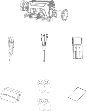
1.1 Box Content
Handheld Thermal Scope (×1)
Power
Adapter (×1)
USB Cable
(×1)
Battery
Charger (×1)
Manual (×1)
Battery (×4)
Lens
Cleaning
Cloth (×1)
1.2 Overview
The handheld thermal scope is equipped with
high-sensitivity IR detector, and adopts
advanced thermal imaging technology, to get
clear view in poor visibility or dark
environment.
It helps aiming at the target and measuring the
distance.
The scope is not only small in size and light in
weight, but also strong and durable. It can aim
at the moving target and meets the outdoor
using condition. The thermal scope can be
widely used in patrolling, crime hunting, and
shooting, etc.
1.3 Features
High performance chip, and DDE
(Digital Detail Enhancement) technique
1024 × 768 Resolution OLED display
Built-in rechargeable Li-ion battery
Up to 8 hours continuous running
USB Cable
Small in size and light in weight
IPX7 water-proof
1.4 Functions
Distance Measurement
The device realizes distance measurement
function after marking the top and bottom of
target, and input the target height.
Range Table Correction
The crosshair helps you to aim at the target fast
and accurately.
Picture in Picture
The device zooms in the central part of the live
view, and displays it inside the live view, so
that you can see the details.
Wi-Fi Hot Spot
Device can capture snapshots, record videos,
and set parameters via APP after being
connected to your phone.
DPC
The camera can correct the defective pixels on
the screen which are not performing as
expected.
GPS Function
The device can be located with GPS system.
Storage
Built-in memory module (up to 16 GB)
supports video recording/snapshot capturing.
Digital Zoom
Device supports 1×, 2×, and 4× digital zoom.
CVBS Output
The device can be connected to a CVBS cable.
2 Appearance
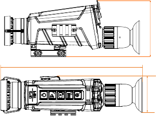
2.1 Dimensions
Take the figure below for the dimensions of the
thermal scope.
60
Unit:mm
235
100
95mm(3.74”)
65mm(2.56”)
225mm(8.86”)
Note: the dimension varies according to
different camera models.
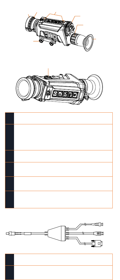
2.2 Scope Interfaces
Take the figure below for the interfaces
description of thermal scope.
Water-proof Aviation Plug Connector
1
Lens Cover
Cover the lens.
2
Objective Lens
Adjust the distance
between the lens and the
sensor to view the target
much clearer.
3
Focus Ring
Adjust the sight view.
4
Buckling Bolt
Loosen the buckling bolt to
install the batteries.
5
Locking Screw
Secure the scope to the
gun/base.
6
Aviation Plug
Connector
Connect with the output
cables.
BNC
USB
DB9
1
BNC
Connect it to the display screen.
2
USB
Connect it to your PC to backup
videos/images.
视度调节圈
眼罩
锁紧螺母
镜头盖
按键
手拧螺钉
物镜
Lens Cover
Locking Screw
Button
Bucking Bolt
Focus Ring
Eyepiece
Objective Lens
3
DB9
Reserved.
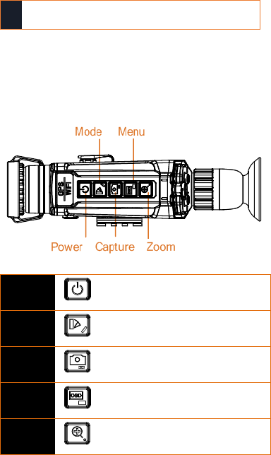
2.3 Buttons
Take the figure below for the buttons
description of thermal scope.
Power
Press: Power On
Hold: Power Off
Mode
Press: Switch Pallet
Hold: Distance Measure
Capture
Press: Capture Snapshot
Hold: Start/Stop Record Video
Menu
Press: OSD On/Off
Hold: Menu Operation
Zoom ±
Press: Digital Zoom
Hold: Enable/Disable Crosshair
Note: For detailed operations of the menu,
refer to Menu Operation Section.
3 Basic Operations
3.1 Charging the Battery
Please charge the scope with the delivered
power adapter. The charging temperature
should be 0 °C to 45 °C (32 °F to 113 °F).
Steps:
1. Take the proper plug adapter.
2. Push and hold it, at the mean time slide it
toward the inside to assemble the power
adapter.
电源键
模式键
拍摄键
菜单键
变倍键
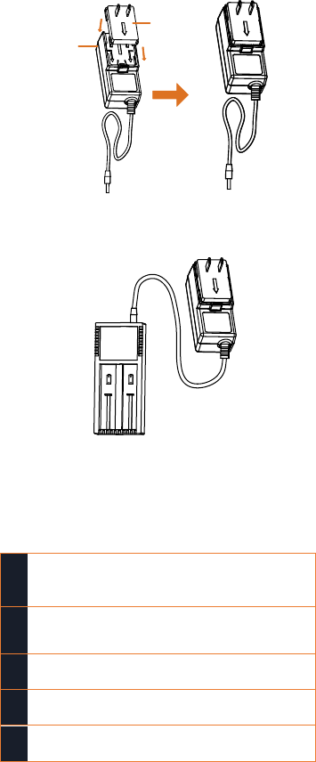
1
2
Plug
Adapter
Charger
Base
3. Connect the power adapter to the battery
charger.
4. Insert the batteries in the charger with
positive/negative terminals corresponded.
Note:
The charger will detect the battery’s status, and
show it on the display. The status description
are shown below:
1
Model & battery
bars
Standby mode
2
Unlighted
Power-saving mode
Press any button.
3
Err
Battery is damaged.
4
Blinking
Battery is being charged.
5
Chg.Finish
Battery is fully charged.
5. Complete battery charging and
disassemble the battery.
3.2 Install the Battery
Turn on the scope, and the OSD (on-screen
display) shows the battery information. When it
says: Low Battery, charge the battery in time.
Steps:
1. Anticlockwise rotate the buckling knob to
loosen it.
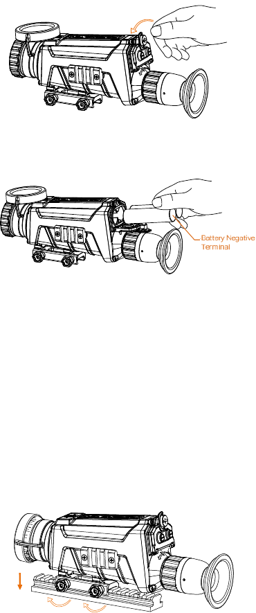
2. Make sure the battery’s positive terminal
is heading the inside, and insert the
batteries.
3. Clockwise rotate the buckling knob to
tighten it.
Note: For long-time not using the device, take
the battery away.
3.3 Secure the Scope
Notes:
Turn off the scope first.
Use the Non-dust cloth to clear the scope
base and your gun’s base.
Step:
Install the scope to the gun base as arrow 1, and
then tighten the knobs to secure the scope as
arrow 2.
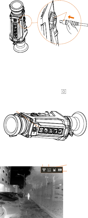
3.4 Connect Cable
Note:
Do NOT drag the cables when you connect it to
the scope.
Step:
Make sure the red dot of the cable aligns with
the red dot of the aviation plug connector, and
connect the cable.
松
电池负极
2
1
Loosen
Red Dot
3.5 Power On/Off
Power On
Press the POWER button to power on the
device. After the device is powered on, you can
view the live view.
Power
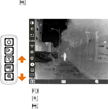
Refer to the figure below for the main view of
the thermal scope.
Wi- Fi Hot Spot Digital ZoomMemory Capacity
Battery
Power Off
When the scope is turned on, hold the POWER
button for four seconds to power off the device.
3.6 Thermal View Observation
Steps:
1. Power on the scope.
2. Pull out the lens cover and place it on the
top of the lens.
Note:
Do NOT drag the lens cover to avoid
damaging it.
3. Hold the scope and make sure the
eyepiece covers your eye.
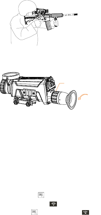
4. Slide the focus ring to adjust the diopter
until the OSD text or image is clear.
Note: You must perform the diopter
adjustment before any further use of the
scope.
5. Point the scope towards the target.
3.7 Files Operation
Connect the thermal scope to your PC with
USB cable, you can export the recorded videos
and captured snapshots.
Before you start:
Turn off the Wi-Fi hot spot first.
1. Hold the button to enter the menu.
2. Select the icon .
3. Press and the icon turns to and
the Wi-Fi hot spot function is disabled.
Step:
Connect the thermal scope to your PC with
USB cable, you can see a detected removable
disk.
Notes:
When you connect the device to
PC for the first time, it installs the
drive program automatically.
When you connect the device to
PC, the device displays images, but
functions such as recording,
capturing and Wi-Fi hot spot are
disabled.
File Export
Steps:
1. Connect the thermal scope to your PC
with USB cable and open the detected
disk.
2. Enter DCIM>100EZVIZ to view the
videos and snapshots.
远视
视度调节圈
Loose
n
Focus Ring
- Select and copy the videos to PC
and play the file with the player.
- Select and copy the snapshots to PC
and view the files.
3. Disconnect the device from your PC.
Upgrade
Steps:
1. Connect the thermal scope to your PC
with USB cable and open the detected
disk.
2. Copy the upgrade file and paste it to the
root directory of the device.
3. Disconnect the device from your PC.
4. Reboot the thermal scope and the device
upgrades automatically. The upgrading
process will be displayed in the main
interface.
4 Device Settings
4.1 Menu Operation
When the scope is turned on, hold the button
for three seconds to display the OSD
menu.
OK
Previous OK/Switc h Next
Press to move the cursor up.
Press to move the cursor down.
Press to confirm.
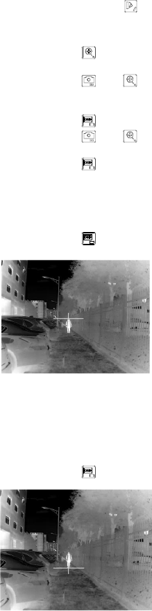
4.2 Distance Measurement
Before you start:
Make sure you hold the scope steadily to
ensure the accuracy.
Purpose:
Mark the top and bottom of the target in the
distance to calculate the distance.
Steps:
1. In the view node, hold to enter the
distance measurement mode.
2. Define the target height.
a) Press to enter the height
setting interface.
b) Press and to select the
target from Deer, Wolf, Bear, and
Custom.
c) Press to confirm.
d) Press and to set the
target height.
e) Press to confirm.
3. Set the top of the target.
a) Move the thermal scope slightly
to place the top mark above the
target top.
b) Press to confirm.
4. Set the bottom of the target after the
cursor flash.
a) Move the thermal scope slightly
to place the bottom mark below
the target bottom.
b) Press to confirm.
The distance between you and the target
and the height of target will display on
the upper left corner of the live view
interface.
1.8m 10
Note:
Enter the distance measurement interface,
press to view the measured
distance.
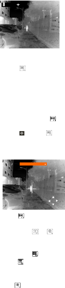
4.3 Range Table Correction
Purpose:
Enable the range table to aim at the target.
Steps:
1. In the view node, hold to show the
menu.
2. Select and press to confirm,
enter the range table correction interface.
A crosshair shows in the center of the
view.
Range Table 1
3. Press to select the range table type.
4. Set the crosshair position.
a) Press or to move the
cursor to the direction icon: ▲, ▼,
◄, and ►.
b) Press to move the crosshair.
5. Hold to exit the settings interface.
4.4 Digital Zoom
Press the button in the view mode, the live
view will switch between 1× digital zoom, 2×
digital zoom, and 4× digital zoom.
4.5 Picture in Picture
Notes:
If digital zoom is enabled, the PIP view
also zooms. If the digital zoom ratio
exceeds 2, the PIP does not zoom.
When you select Upper Right PIP type,
the OSD will be blocked.
Purpose:
The device zooms in the central part of the live
view, and displays it inside the live view, so
that you can see the details.
Steps:
1. In the view node, hold to show the
menu.
2. Select and enter PIP mode. The
details shows in the upper left corner.
When range table is enabled, the
PIP view is the detail of crosshair.
When range table is not enabled,
the PIP view is the detail of
central part.
3. Press to switch the PIP type, upper
left, upper middle, upper right, and off are
selectable.
4. Hold to exit the settings interface.
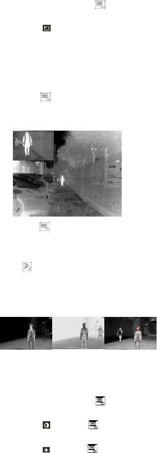
4.6 Palettes Settings
Press to select different palettes to see the
scene in different effects.
White Hot
Black Hot
Red Hot
4.7 Image Settings
Steps:
1. In the view node, hold to show the
menu.
2. Select and press to adjust the
image contrast.
3. Select and press to adjust the
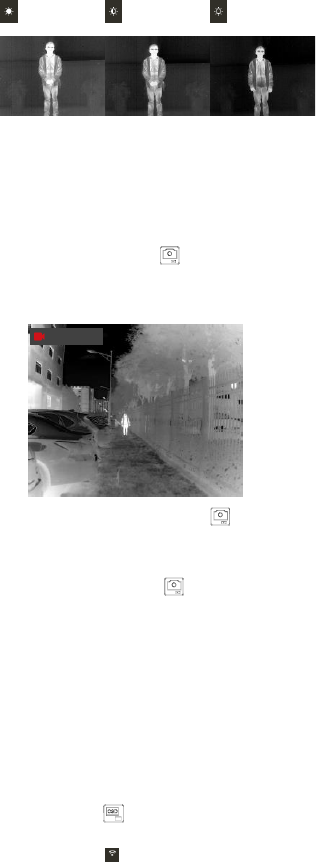
image brightness.
Note:
The brightness is for the screen display, here is
the example of white hot palette mode.
High
Medium
Low
In black hot mode, the brightness of the image
turns in the opposite way.
4.8 Record/Capture
Video Recording
In the view mode, hold for 3 s to record.
In the upper left corner, the recording time
displays.
00:04:29
After recording the video, hold for 3 s
again to stop recording.
Snapshot Capturing
In the view mode, press , the live view
freezes for 1 s, and the snapshot is captured.
4.9 Network Configuration
Connect your phone to the Wi-Fi or hot spot of
the thermal scope, you can configure the
parameters and realize functions of the device.
Wi-Fi
Steps:
1. Hold the button to show the menu of
thermal scope.
2. Press the key to enable Wi-Fi
function.
3. Setting the Wi-Fi name and password of
your phone or the router as follow:
- Wi-Fi Name: WLAN-IPTP.
- Wi-Fi Password: abcd1234.
4. Search the “IVMS-4500” on App Store
(iOS System) or Google Play TM (Android

System) to download and install the app.
5. Open the APP and connect your phone
with the device. You can view the
interface of thermal scope on your
phone.
Hot Spot
Steps:
1. Hold the button to show the menu of
thermal scope.
2. Press the key to enable hot spot
function.
3. Turn on the WLAN and connect to the
hot spot.
- Hot Spot Name: HIK-IPTS Serial
No.
- Hot Spot Password: S + serial No.
4. Search the “IVMS-4500” on App Store
(iOS System) or Google Play TM (Android
System) to download and install the app.
5. Open the APP and connect your phone
with the device. You can view the
interface of thermal scope on your
phone.
4.10 DPC
The camera can correct the defective pixels on
the screen which are not performing as
expected.
Dead Pixel Repair
Purpose:
This function can correct the dead pixel.
Steps:
1. Cover the lens cover.
2. Hold the button to show the menu of
thermal scope.
3. Press the key.
4. Press and to select Dead Pixel
Repair.
5. Press to confirm.
Dead Pixel Restore
Purpose:
This function can restore dead pixel to original
statue when the dead pixel repair or camera
operation is abnormal.
Steps:
1. Cover the lens cover.
2. Hold the button to show the menu of
thermal scope.
3. Press the key.
4. Press and to select Dead Pixel

Restore.
5. Press to confirm.
External Correction
Purpose:
This function can correct the image when the
displaying is not perform good after long time
using.
Steps:
1. Cover the lens cover.
2. Hold the button to show the menu of
thermal scope.
3. Press the key.
4. Press and to select External
Correction.
5. Press to confirm.
4.11 Others
CVBS Output
After connecting the scope to the screen with
CVBS cable, call the menu and select CVBS
and confirm to enable/disable CVBS output.
Reset Device
Select from the menu and confirm to
reboot the scope, and restore all parameters to
default settings.
Version Information
Select from the menu and confirm to view
all the version information.
5 FAQ
Q: The image/crosshair is vague.
A: Perform the diopter adjustment
referring to section 3.3.
Q: Wi-Fi is not found.
A: Examine whether the Wi-Fi function is
turned on. If not, go to OSD menu and
turn on Wi-Fi.
Q: Capturing or recording fails.
A: Examine the items below:
1. Whether the device is connected to
your PC and disabled the capturing and
recording.
2. Whether the storage space is full.
3. Whether the device is low-battery.
Q: There is no GPS signal.
A: Examine the using environment. If the
device receives no signal in indoor
environment, please go to outdoor

spaces. It takes about 10 min to power
on and search for the signal.
Q: There is no CVBS signal output.
A: Examine the items below:
1. Whether the CVBS connection is
loosen.
2. Whether the cable works.
3. Whether the CVBS is enabled in the
OSD menu.
Q: The PC cannot identify the scope.
A: Examine the items below:
1. Whether the device is connected to
your PC with standard USB cable.
2. If you use other USB cables, make sure
the cable length is no longer than 1m.
3. Whether the Wi-Fi function is turned
on. If so, go to OSD menu and turn off
Wi-Fi.
Q: There is no live view.
A: Examine whether the lens cover is
removed.
Q: The OLED display is dark.
A: Examine the items below:
1. Whether you turned on the device by
holding for 3 s.
2. Whether the battery ran out.
3. Whether the batteries are installed
oppositely.