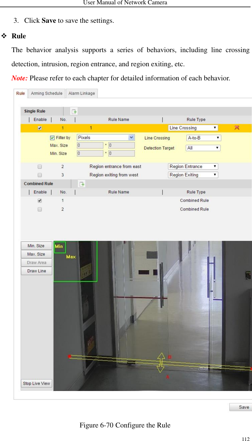
Hangzhou Hikvision Digital Technology I0D2400 Network Camera User Manual
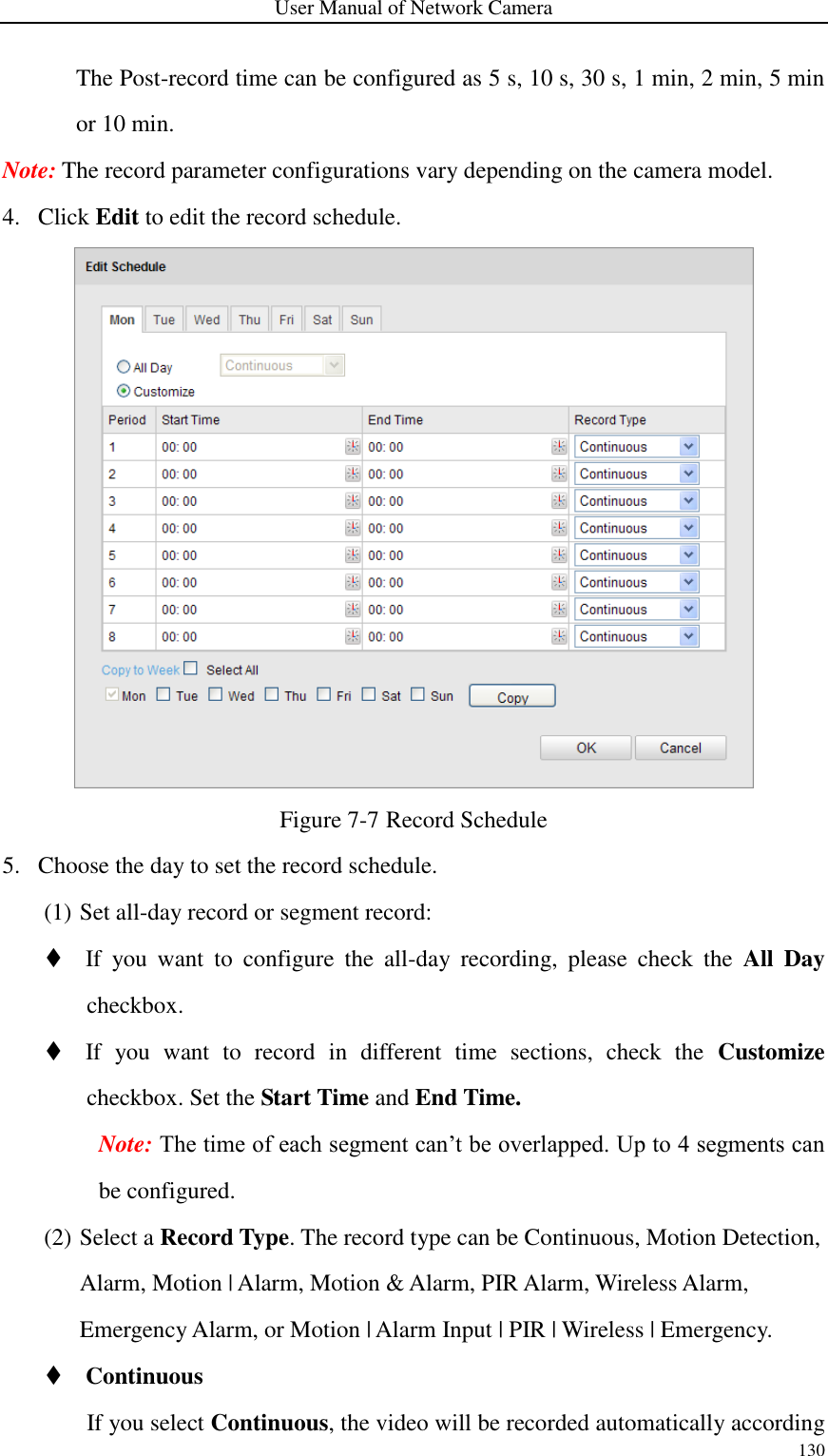
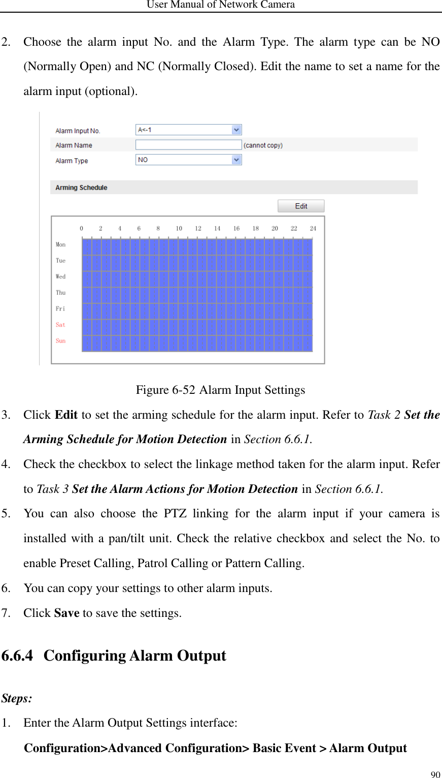
Hangzhou Hikvision Digital Technology Co., Ltd. Network Camera Users Manual
UserManual.wiki
>
Hangzhou Hikvision Digital Technology
>
I0D2400 User Manual
Users Manual
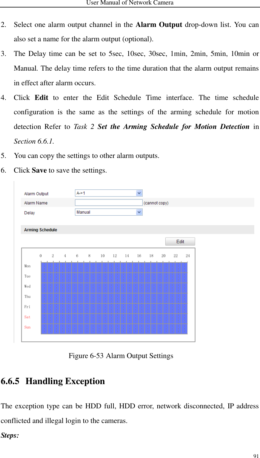
Navigation menu
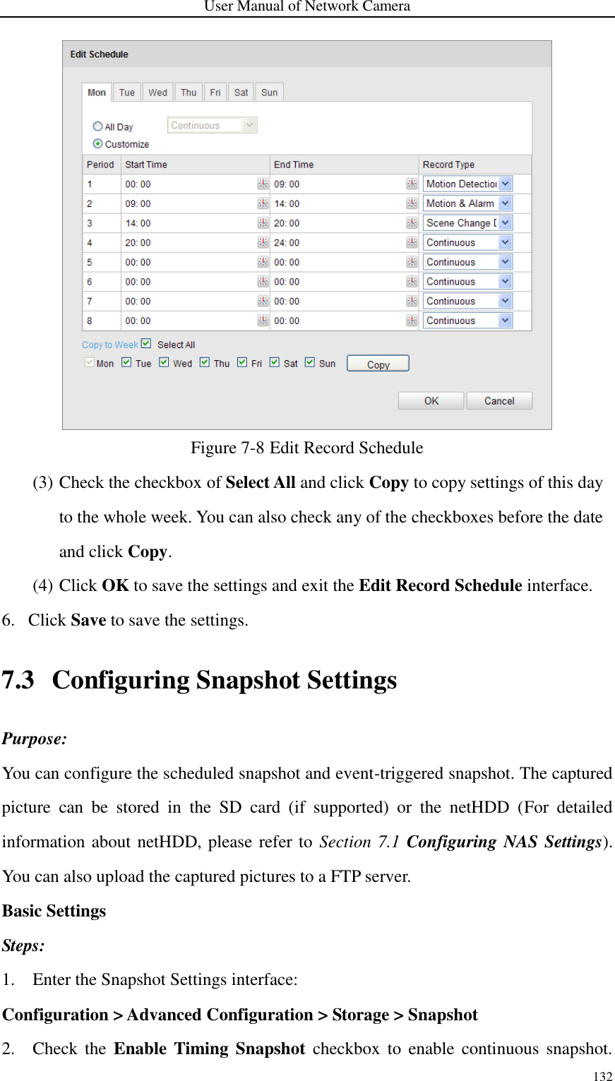
Upload a User Manual
Namespaces
Wiki Guide
HTML
PDF
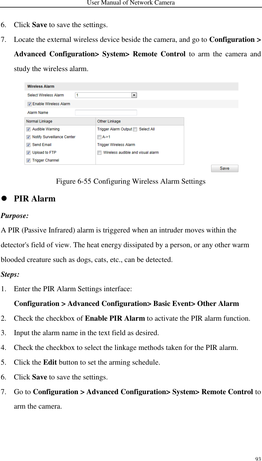
Info
Views
User Manual
Discussion / Help
Navigation
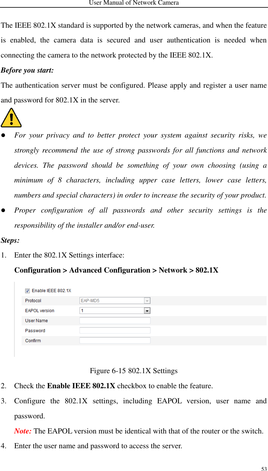
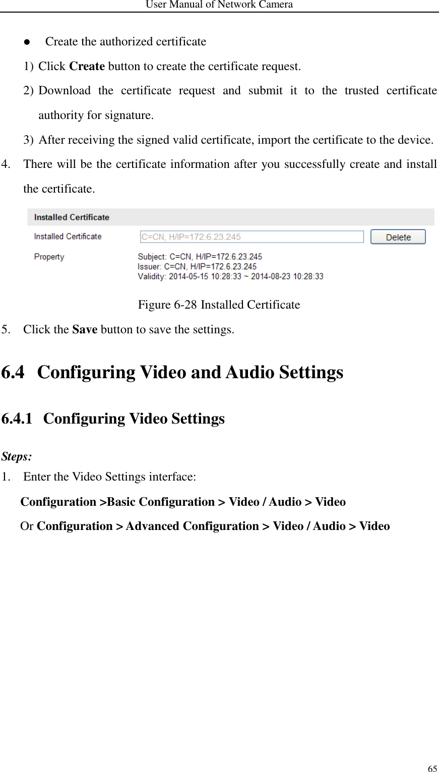
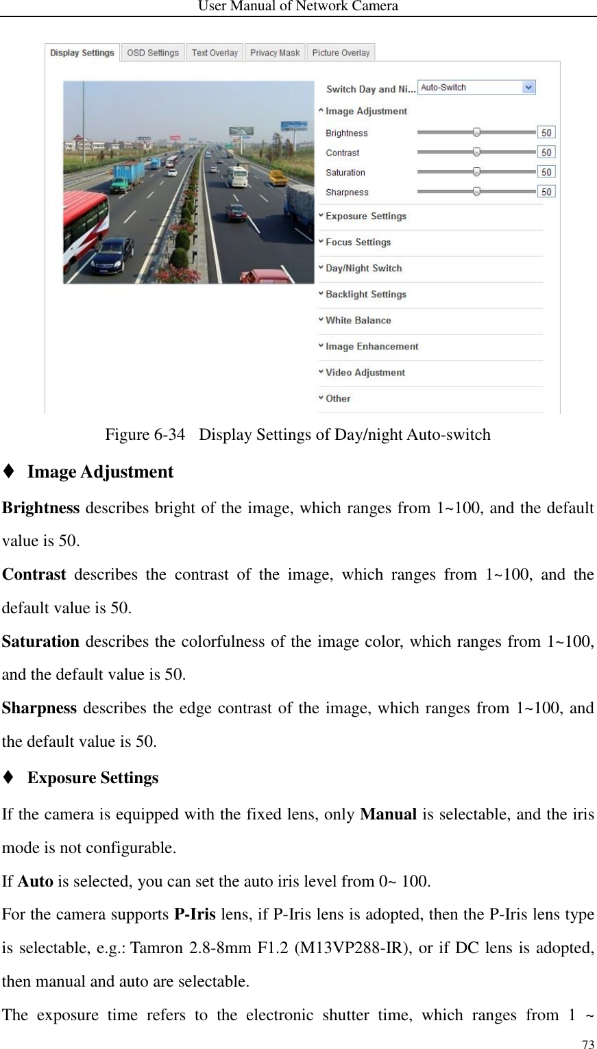
![User Manual of Network Camera 76 Figure 6-36 White Balance Image Enhancement Digital Noise Reduction: DNR reduces the noise in the video stream. OFF, Normal Mode and Expert Mode are selectable. Set the DNR level from 0~100, and the default value is 50 in Normal Mode. Set the DNR level from both space DNR level [0~100] and time DNR level [0~100] in Expert Mode. Defog Mode: You can enable the defog function when the environment is foggy and the image is misty. It enhances the subtle details so that the image appears clearer. Electrical Image Stabilizer: EIS reduces the effects of vibration in a video. Grey Scale: You can choose the range of the grey scale as [0-255] or [16-235]. Video Adjustment Mirror: It mirrors the image so you can see it inversed. Left/Right, Up/Down, Center, and OFF are selectable. Rotate: To make a complete use of the 16:9 aspect ratio, you can enable the rotate function when you use the camera in a narrow view scene. When installing, turn the camera to the 90 degrees or rotate the 3-axis lens to 90 degrees, and set the rotate mode as on, you will get a normal view of the scene with 9:16 aspect ratio to ignore the needless information such as the wall, and get more meaningful information of the scene. Scene Mode: Choose the scene as indoor or outdoor according to the real environment. Video Standard: 50 Hz and 60 Hz are selectable. Choose according to the different video standards; normally 50 Hz for PAL standard and 60 Hz for NTSC standard. Capture Mode: It’s the selectable video input mode to meet the different demands of field of view and resolution. Lens Distortion Correction: Select ON / OFF to enable / disable the lens distortion correction. The distorted image caused by the wide-angle lens can be corrected if this function enabled. Other](https://usermanual.wiki/Hangzhou-Hikvision-Digital-Technology/I0D2400/User-Guide-3488779-Page-80.png)

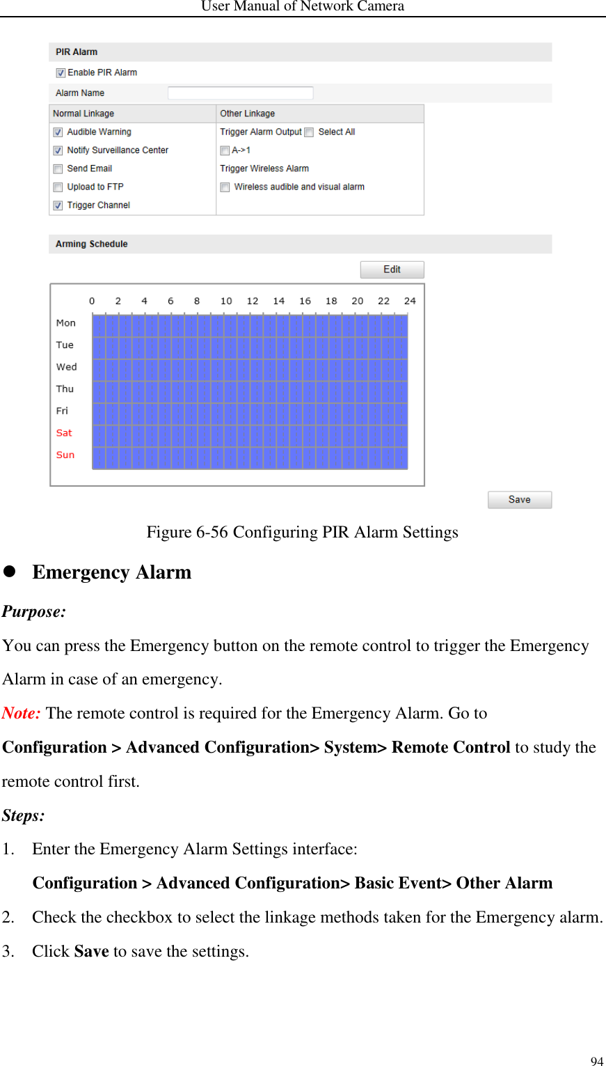
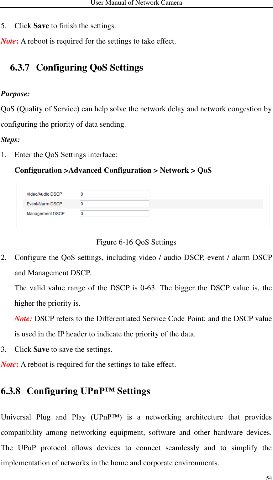
![User Manual of Network Camera 95 Figure 6-57 Configuring Emergency Alarm Settings 6.6.7 Configuring Audio Exception Detection Purpose: Audio exception detection function detects the abnormal sounds in the surveillance scene, such as the sudden increase / decrease of the sound intensity, and some certain actions can be taken when the alarm is triggered. Note: Audio exception detection function varies according to different camera models. Steps: 1. Enter the Audio Exception Detection settings interface: Configuration > Advanced Configuration> Smart Event> Audio Exception Detection 2. Check the checkbox of Audio Loss Exception to enable the audio loss detection function. 3. Check the checkbox of Sudden Increase of Sound Intensity Detection to detect the sound steep rise in the surveillance scene. You can set the detection sensitivity and threshold for sound steep rise. 4. Check the checkbox of Sudden Decrease of Sound Intensity Detection to detect the sound steep drop in the surveillance scene. You can set the detection sensitivity and threshold for sound steep drop. Notes: Sensitivity: Range [1-100], the smaller the value is, the more severe the change should be to trigger the detection.](https://usermanual.wiki/Hangzhou-Hikvision-Digital-Technology/I0D2400/User-Guide-3488779-Page-99.png)
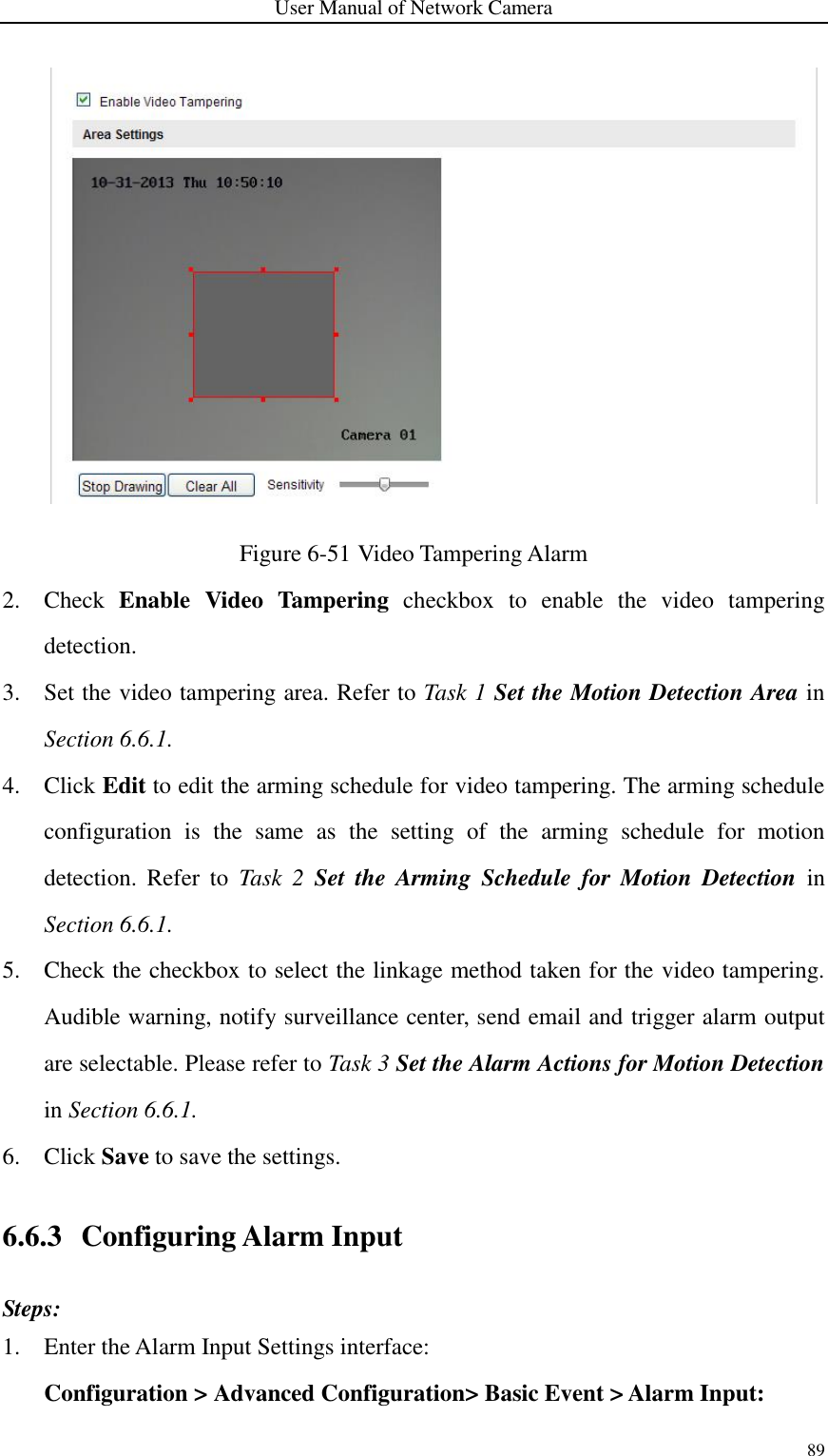
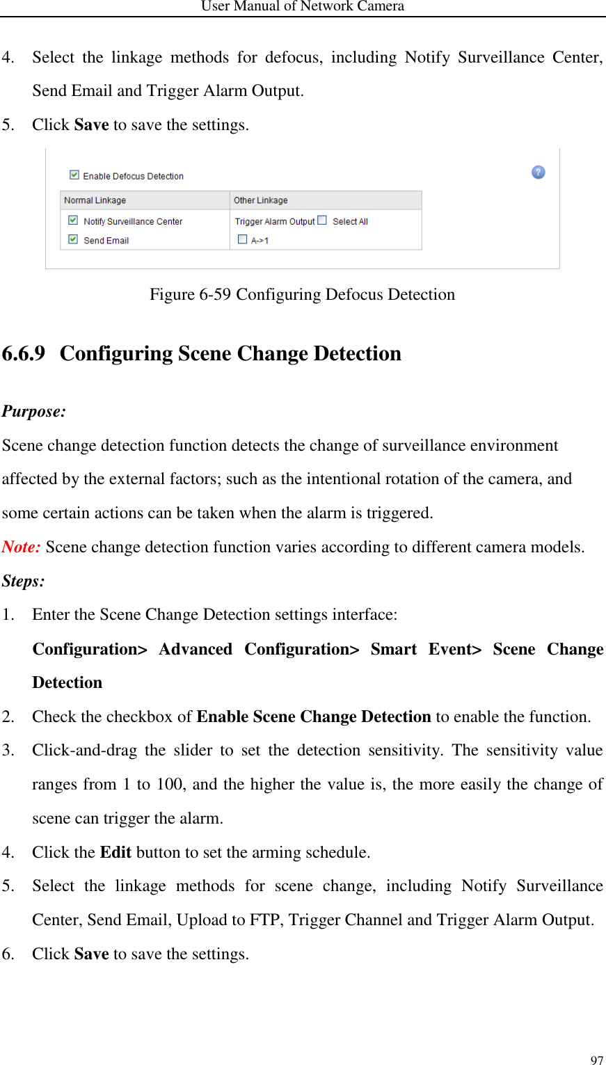
![User Manual of Network Camera 96 Sound Intensity Threshold: Range [1-100], it can filter the sound in the environment, the louder the environment sound, the higher the value should be. You can adjust it according to the real environment. 5. You can view the real-time volume of the sound. 6. Click the Edit button to set the arming schedule. 7. Select the linkage methods for audio exception, including Notify Surveillance Center, Send Email, Upload to FTP, Trigger Channel for recording and Trigger Alarm Output. 8. Click Save to save the settings. Figure 6-58 Configuring Audio Exception Detection 6.6.8 Configuring Defocus Detection Purpose: The image blur caused by defocus of the lens can be detected, and some certain actions can be taken when the alarm is triggered. Note: Defocus detection function varies according to different camera models. Steps: 1. Enter the Defocus Detection settings interface: Configuration> Advanced Configuration> Smart Event> Defocus Detection 2. Check the checkbox of Enable Defocus Detection to enable the function. 3. Click-and-drag the slider to set the detection sensitivity. The sensitivity value ranges from 1 to 100, and the higher the value is, the more easily the defocus image can trigger the alarm.](https://usermanual.wiki/Hangzhou-Hikvision-Digital-Technology/I0D2400/User-Guide-3488779-Page-100.png)
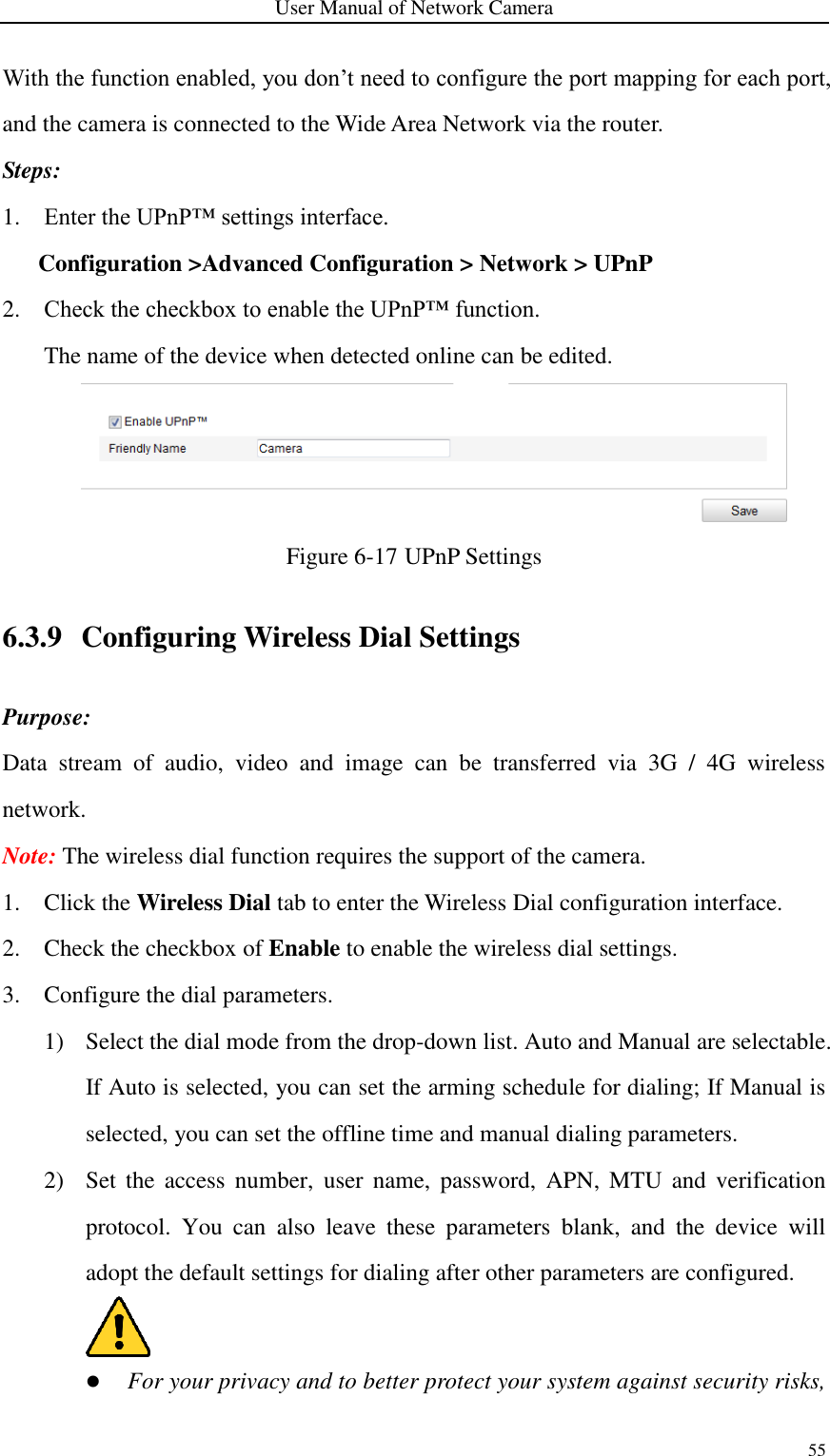
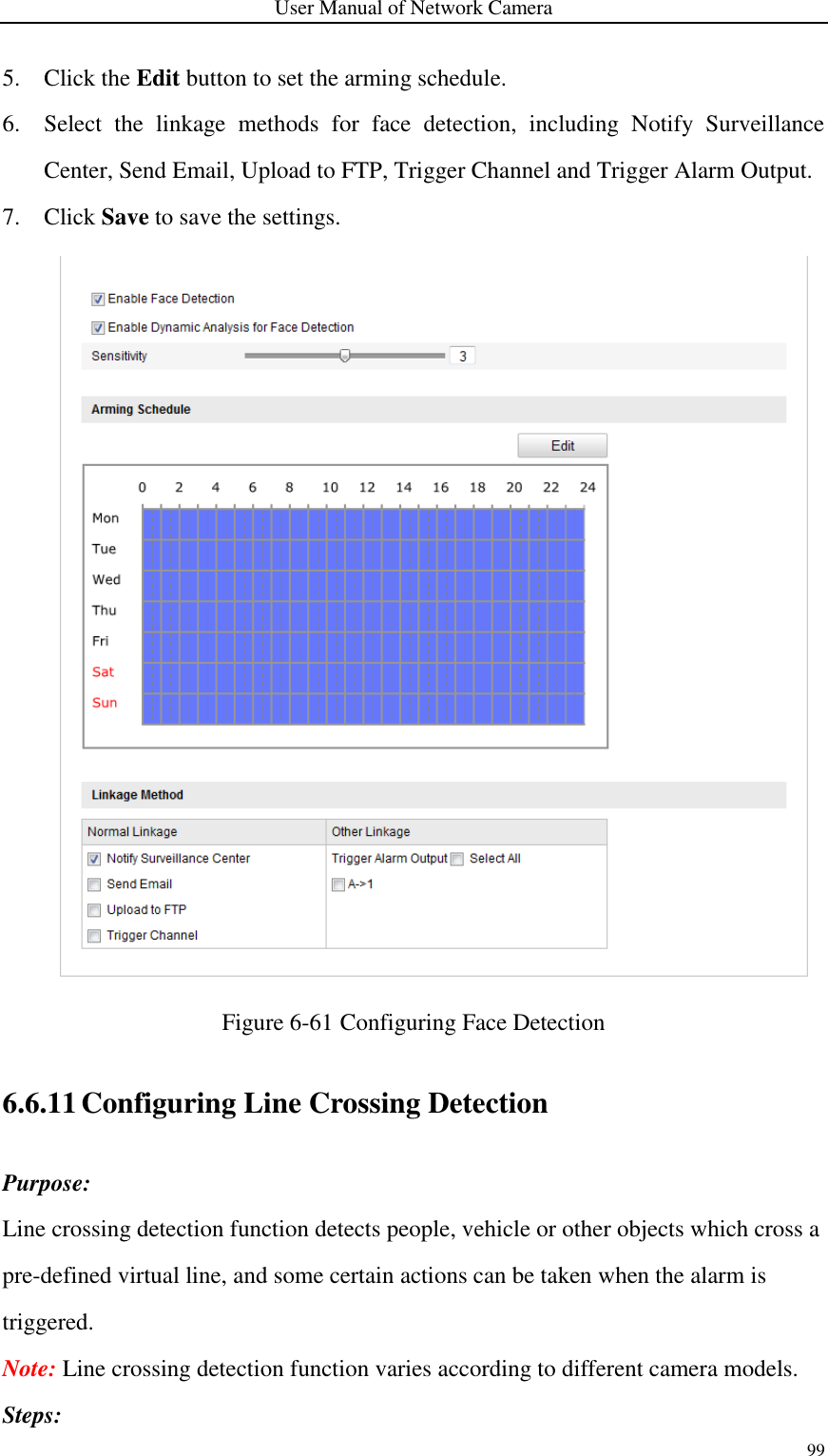
![User Manual of Network Camera 98 Figure 6-60 Configuring Scene Change Detection 6.6.10 Configuring Face Detection Purpose: Face detection function detects the face appears in the surveillance scene, and some certain actions can be taken when the alarm is triggered. Note: Face detection function varies according to different camera models. Steps: 1. Enter the Face Detection settings interface: Configuration> Advanced Configuration> Smart Event> Face Detection 2. Check the checkbox of Enable Face Detection to enable the function. 3. (Optional) Check the checkbox of Enable Dynamic Analysis for Face Detection, and then the detected face is marked with green rectangle on the live video. Note: To mark the detected face on the live video, go to Local Configuration> Live View Parameters and enable the Rules. 4. Click-and-drag the slider to set the detection sensitivity. Sensitivity: Range [1-5]. The higher the value is, the more easily the face can be detected.](https://usermanual.wiki/Hangzhou-Hikvision-Digital-Technology/I0D2400/User-Guide-3488779-Page-102.png)
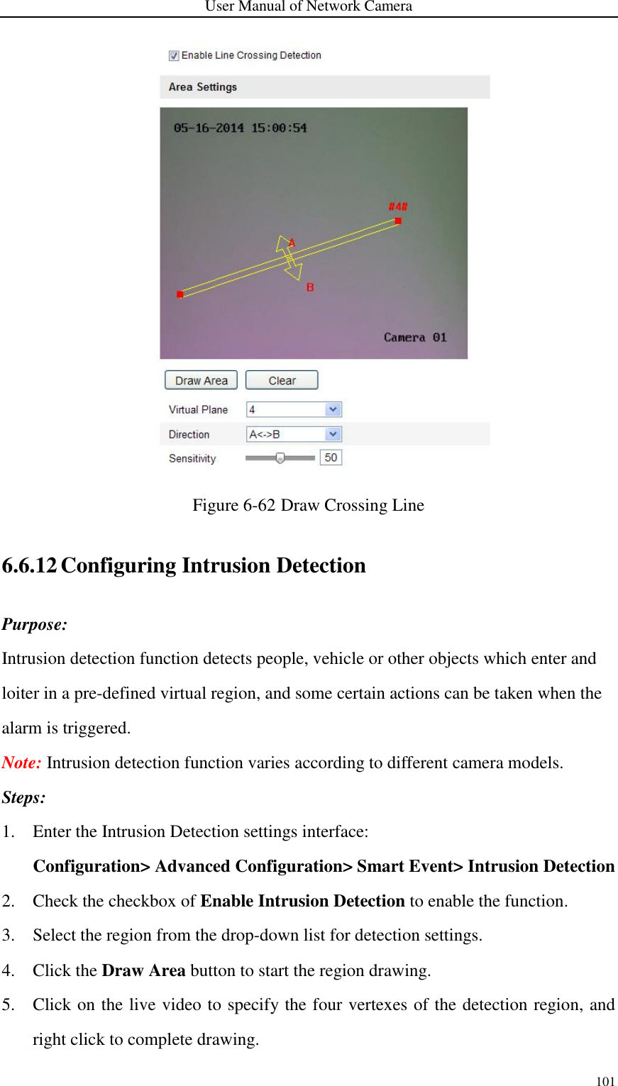
![User Manual of Network Camera 100 1. Enter the Line Crossing Detection settings interface: Configuration> Advanced Configuration> Smart Event> Line Crossing Detection 2. Check the checkbox of Enable Line Crossing Detection to enable the function. 3. Select the line from the drop-down list for detection settings. 4. Click the Draw Area button, and a virtual line is displayed on the live video. 5. Click-and-drag the line, and you can locate it on the live video as desired. Click on the line, two red squares are displayed on each end, and you can click-and-drag one of the red squares to define the shape and length of the line. 6. Select the direction for line crossing detection. And you can select the directions as A<->B, A ->B, and B->A. A<->B: Only the arrow on the B side shows; when an object going across the plane with both direction can be detected and alarms are triggered. A->B: Only the object crossing the configured line from the A side to the B side can be detected. B->A: Only the object crossing the configured line from the B side to the A side can be detected. 7. Click-and-drag the slider to set the detection sensitivity. Sensitivity: Range [1-100]. The higher the value is, the more easily the line crossing action can be detected. 8. Repeat the above steps to configure other lines. Up to 4 lines can be set. You can click the Clear button to clear all pre-defined lines. 9. Click the Edit button to set the arming schedule. 10. Select the linkage methods for line crossing detection, including Notify Surveillance Center, Send Email, Upload to FTP, Trigger Channel and Trigger Alarm Output. 11. Click Save to save the settings.](https://usermanual.wiki/Hangzhou-Hikvision-Digital-Technology/I0D2400/User-Guide-3488779-Page-104.png)
![User Manual of Network Camera 102 6. Set the time threshold, detection sensitivity and object percentage for intrusion detection. Threshold: Range [0s-10s], the threshold for the time of the object loitering in the region. If you set the value as 0, alarm is triggered immediately after the object entering the region. Sensitivity: Range [1-100]. The value of the sensitivity defines the size of the object which can trigger the alarm. When the sensitivity is high, a very small object can trigger the alarm. Percentage: Range [1-100]. Percentage defines the ratio of the in-region part of the object which can trigger the alarm. For example, if the percentage is set as 50%, when the object enters the region and occupies half of the whole region, the alarm is triggered. 7. Repeat the above steps to configure other regions. Up to 4 regions can be set. You can click the Clear button to clear all pre-defined regions. 8. Click the Edit button to set the arming schedule. 9. Select the linkage methods for intrusion detection, including Notify Surveillance Center, Send Email, Upload to FTP, Trigger Channel and Trigger Alarm Output. 10. Click Save to save the settings. Figure 6-63 Configuring Intrusion Area](https://usermanual.wiki/Hangzhou-Hikvision-Digital-Technology/I0D2400/User-Guide-3488779-Page-106.png)
![User Manual of Network Camera 103 6.6.13 Configuring Region Entrance Detection Purpose: Region entrance detection function detects people, vehicle or other objects which enter a pre-defined virtual region from the outside place, and some certain actions can be taken when the alarm is triggered. Note: Region entrance detection function varies according to different camera models. Steps: 1. Enter the Region Entrance Detection settings interface: Configuration> Advanced Configuration> Smart Event> Region Entrance Detection 2. Check the checkbox of Enable Region Entrance Detection to enable the function. 3. Select the region from the drop-down list for detection settings. 4. Click the Draw Area button to start the region drawing. 5. Click on the live video to specify the four vertexes of the detection region, and right click to complete drawing. 6. Click-and-drag the slider to set the detection sensitivity. Sensitivity: Range [1-100]. The value of the sensitivity defines the size of the object which can trigger the alarm. When the sensitivity is high, a very small object entering the region can trigger the alarm. 7. Repeat the above steps to configure other regions. Up to 4 regions can be set. You can click the Clear button to clear all pre-defined regions. 8. Click the Edit button to set the arming schedule. 9. Select the linkage methods for region entrance detection, including Notify Surveillance Center, Send Email, Upload to FTP, Trigger Channel and Trigger Alarm Output. 10. Click Save to save the settings.](https://usermanual.wiki/Hangzhou-Hikvision-Digital-Technology/I0D2400/User-Guide-3488779-Page-107.png)
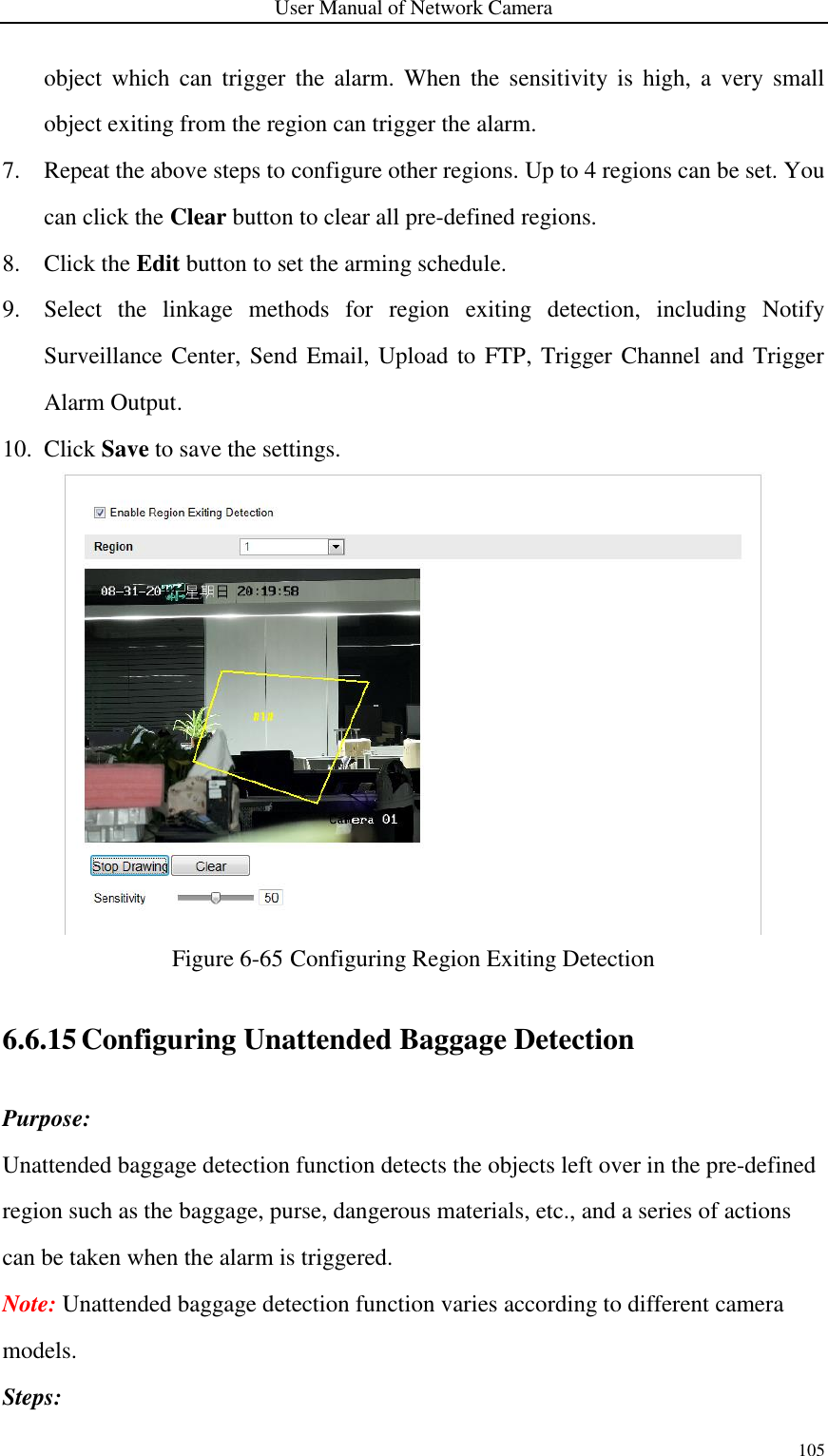
![User Manual of Network Camera 104 Figure 6-64 Configuring Region Entrance Detection 6.6.14 Configuring Region Exiting Detection Purpose: Region exiting detection function detects people, vehicle or other objects which exit from a pre-defined virtual region, and some certain actions can be taken when the alarm is triggered. Note: Region exiting detection function varies according to different camera models. Steps: 1. Enter the Region Exiting Detection settings interface: Configuration> Advanced Configuration> Smart Event> Region Exiting Detection 2. Check the checkbox of Enable Region Exiting Detection to enable the function. 3. Select the region from the drop-down list for detection settings. 4. Click the Draw Area button to start the region drawing. 5. Click on the live video to specify the four vertexes of the detection region, and right click to complete drawing. 6. Click-and-drag the slider to set the detection sensitivity. Sensitivity: Range [1-100]. The value of the sensitivity defines the size of the](https://usermanual.wiki/Hangzhou-Hikvision-Digital-Technology/I0D2400/User-Guide-3488779-Page-108.png)
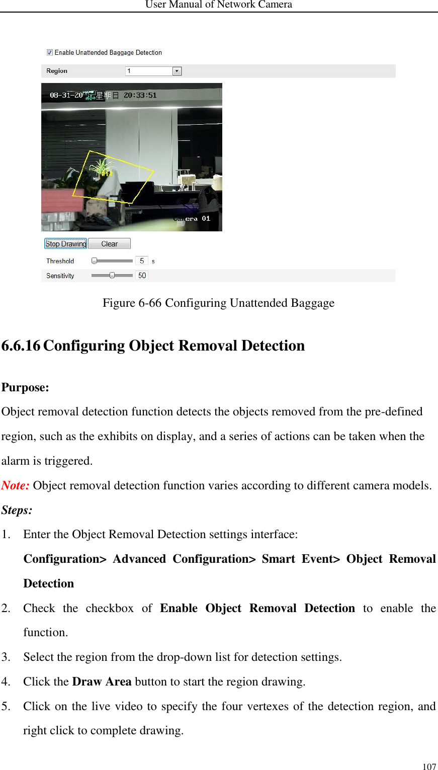
![User Manual of Network Camera 106 1. Enter the Unattended Baggage Detection settings interface: Configuration> Advanced Configuration> Smart Event> Unattended Baggage Detection 2. Check the checkbox of Enable Unattended Baggage Detection to enable the function. 3. Select the region from the drop-down list for detection settings. 4. Click the Draw Area button to start the region drawing. 5. Click on the live video to specify the four vertexes of the detection region, and right click to complete drawing. 6. Set the time threshold and detection sensitivity for unattended baggage detection. Threshold: Range [5s-20s], the threshold for the time of the objects left over in the region. If you set the value as 10, alarm is triggered after the object is left and stay in the region for 10s. Sensitivity: Range [1-100]. The value of sensitivity defines the similarity degree of the background image. Usually, when the sensitivity is high, a very small object left in the region can trigger the alarm. 7. Repeat the above steps to configure other regions. Up to 4 regions can be set. You can click the Clear button to clear all pre-defined regions. 8. Click the Edit button to set the arming schedule. 9. Select the linkage methods for unattended baggage detection, including Notify Surveillance Center, Send Email, Upload to FTP, Trigger Channel and Trigger Alarm Output. 10. Click Save to save the settings.](https://usermanual.wiki/Hangzhou-Hikvision-Digital-Technology/I0D2400/User-Guide-3488779-Page-110.png)
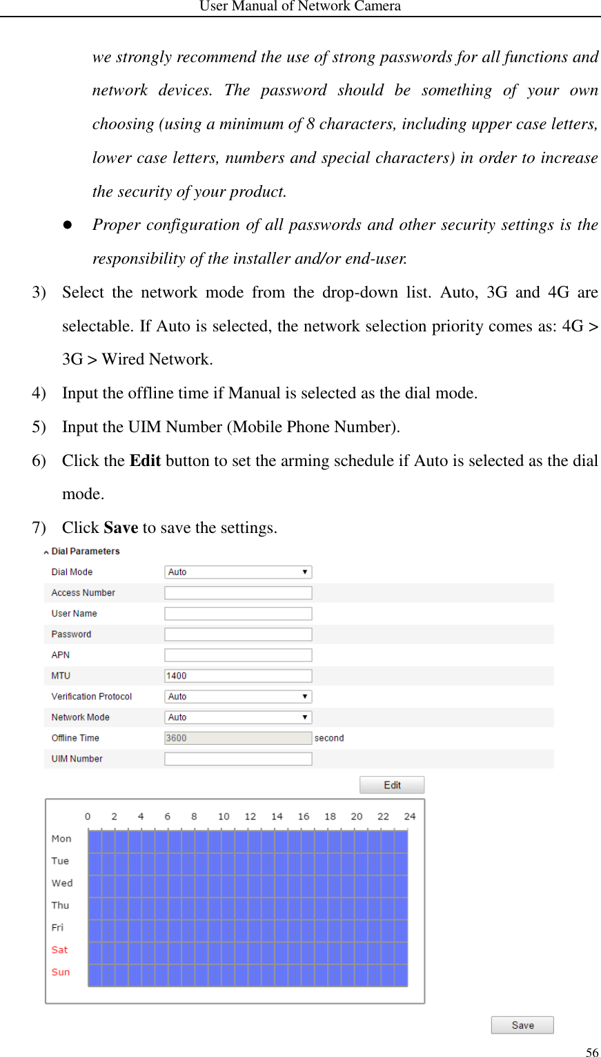
![User Manual of Network Camera 108 6. Set the time threshold and detection sensitivity for object removal detection. Threshold: Range [5s-20s], the threshold for the time of the objects removed from the region. If you set the value as 10, alarm is triggered after the object disappears from the region for 10s. Sensitivity: Range [1-100]. The value of sensitivity defines the similarity degree of the background image. Usually, when the sensitivity is high, a very small object taken from the region can trigger the alarm. 7. Repeat the above steps to configure other regions. Up to 4 regions can be set. You can click the Clear button to clear all pre-defined regions. 8. Click the Edit button to set the arming schedule. 9. Select the linkage methods for object removal detection, including Notify Surveillance Center, Send Email, Upload to FTP, Trigger Channel and Trigger Alarm Output. 10. Click Save to save the settings. Figure 6-67 Configuring Object Removal Detection](https://usermanual.wiki/Hangzhou-Hikvision-Digital-Technology/I0D2400/User-Guide-3488779-Page-112.png)
![User Manual of Network Camera 114 6. Click Save to save the settings. 7. Click Arming Schedule tab, click Edit to set the schedule time for each rule, and click Save to save the settings. 8. Click Alarm Linkage tab, check the checkbox of corresponding linkage method for each rule, and click Save to save the settings. Advanced Configuration ● Parameter Configure the following parameters to detail the configuration. Figure 6-71 Advanced Configuration Detection Sensitivity [0~4]: Refers to the sensitivity of the camera detects a target. The higher the value, the easier a target be recognized, and the higher the misinformation is. The default value of 3 is recommended. Background Update Rate [0~4]: It refers to the speed of the new scene replaces the previous scene. The default value of 3 is recommended. Single Alarm: If single alarm is selected, the target in the configured area will trigger the alarm for only once. If it is not checked, the same target will cause the continuous alarm in the same configured area. Leave Interference Suppression: Check this checkbox to stop the interference caused by the leaves in the configured area. Output Type: Select the position of the frame. Target center, bottom center, and top centers are selectable. E.g.: The target will be in the center of the frame if target center is selected.](https://usermanual.wiki/Hangzhou-Hikvision-Digital-Technology/I0D2400/User-Guide-3488779-Page-118.png)
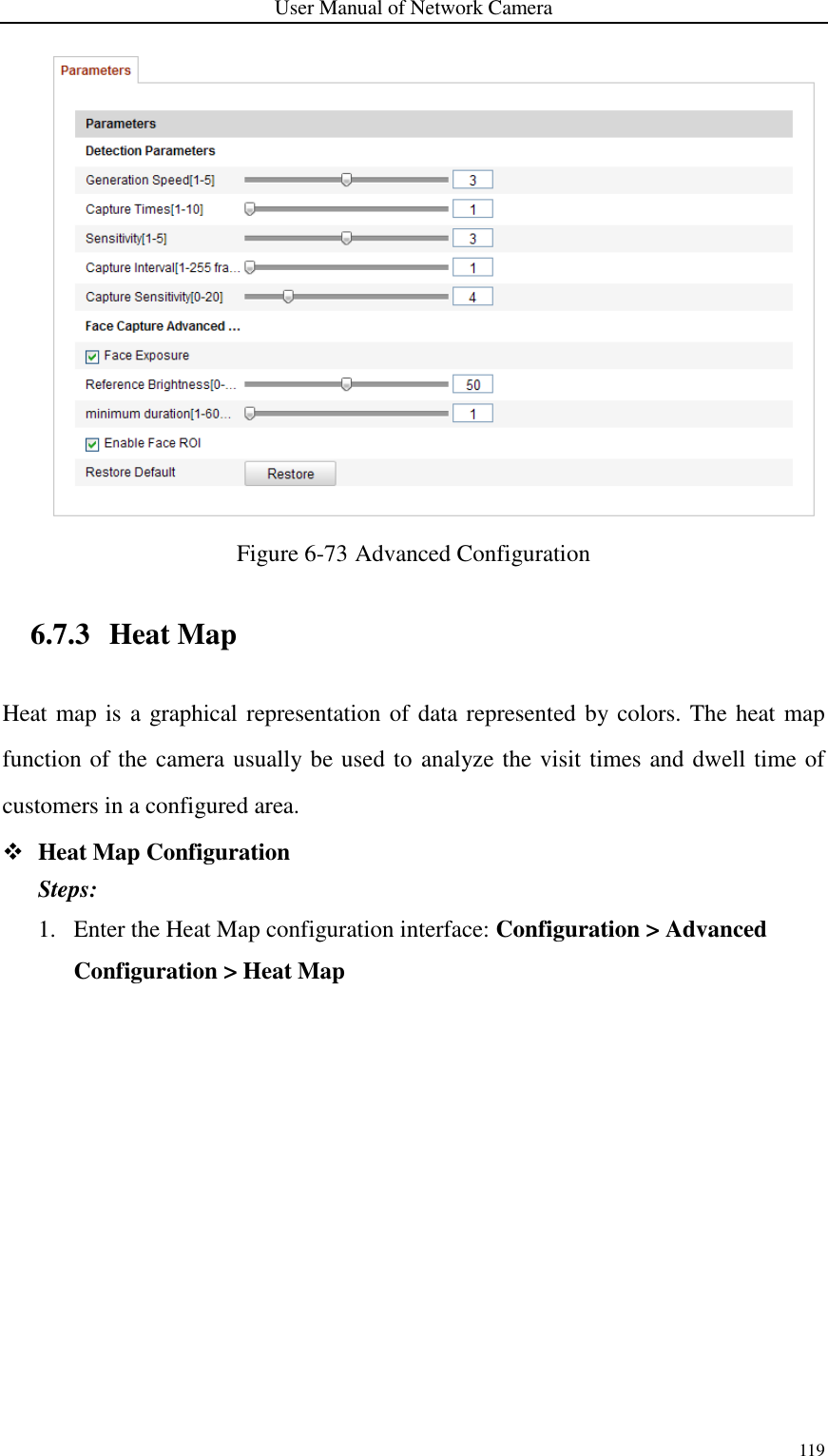
![User Manual of Network Camera 117 Notes: ● Click Delete to delete the drawn areas. ● If the live view is stopped, there is no way to draw the shield regions. 3. Click Save to save the settings. Rule Steps: 1. Check the checkbox of Rule to enable rules of face capture. 2. Click Minimize Pupil Distance to draw the minimum pupil distance. The distance of the drawn pupil will be displayed on the box below the live view. The minimize pupil distance refers to the minimum square size composed by the area between two pupils, and it is the basic standard for a camera to identify a target. 3. Click Draw Area to draw the area you want the face capture to take effect. Draw area by left click end-points in the live view window, and right click to finish the area drawing. Notes: Polygon area (4~10 sides) sides is supported. If the live view is stopped, there is no way to draw the configured area. 4. Click Save to save the settings. Advanced Configuration Configure the following parameters according to your actual environment. Detection Parameters: Generation Speed [1~5]: The speed to identify a target. The higher the value, the faster the target will be recognized. Setting the value quite low, and if there was a face in the configured area from the start, this face will not be captured. It can reduce the misinformation of the faces in the wall painting or posters. The default value of 3 is recommended. Capture Times [1~10]: Refers to the capture times a face will be captured during its stay in the configured area. The default value is 1. Sensitivity [1~5]: The sensitivity to identify a target. The higher the value, the easier a face will be recognized, and the higher misinformation is. The default value of 3 is](https://usermanual.wiki/Hangzhou-Hikvision-Digital-Technology/I0D2400/User-Guide-3488779-Page-121.png)
![User Manual of Network Camera 118 recommended. Capture Interval [1~255 Frame]: The frame interval to capture a picture. If you set the value as 1, which is the default value, it means the camera captures the face in every frame. Capture Sensitivity [0~20]: The threshold the camera treats the target as a face. Only when the face score generated by the algorithm is equal or higher than the value, the camera will treat the target as a face. The default value of 2 is recommended. Face Capture Advanced Parameters: Face Exposure: Check the checkbox to enable the face exposure. Reference Brightness [0~100]: The reference brightness of a face in the face exposure mode. If a face is detected, the camera adjusts the face brightness according to the value you set. The higher the value, the brighter the face is. Minimum Duration [1~60min]: The minimum duration of the camera exposures the face. The default value is 1 minute. Note: If the face exposure is enabled, please make sure the WDR function is disabled, and the manual iris is selected. Enable Face ROI: If the camera captures a face, the face area will be treated as the region of interest, and the image quality of this area will be improved. Restore Default: Click Restore to restore all the settings in advanced configuration to the factory default.](https://usermanual.wiki/Hangzhou-Hikvision-Digital-Technology/I0D2400/User-Guide-3488779-Page-122.png)
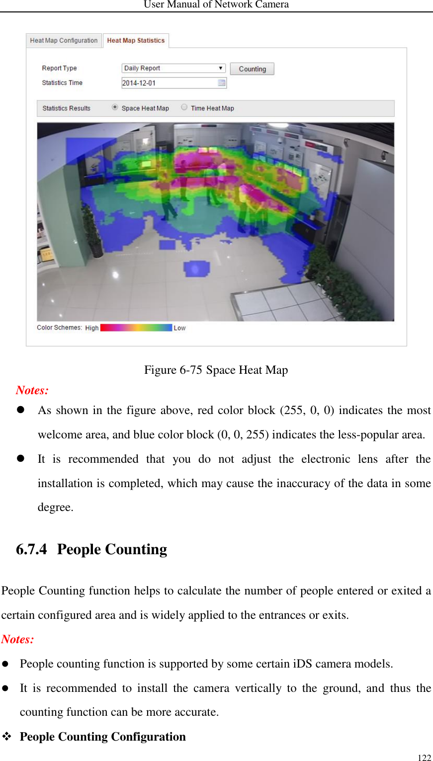
![User Manual of Network Camera 120 Figure 6-74 Heat Map Configuration 2. Select Heat Map Configuration tab to set the detailed parameters. 3. Check the checkbox of Enable Heat Map to enable the function. 4. Click Draw Area to define the area for heat value statistics. Draw area by left click four end-points in the live view window, and right click to finish the area drawing. Up to 8 areas are configurable. Note: You can click Select All to select the whole live view window as the configured area. Or click Delete to delete the current drawn area. 5. Configure the parameters for drawn area. Detection Sensitivity [0~100]: It refers to the sensitivity of the camera identify a target. The over-high sensitivity may cause the misinformation. It is recommended you set the sensitivity as the default value, which is 50. Background Update Rate [0~100]: It refers to the speed of the new scene replaces the previous scene. E.g.: In front of a cabinet, the people besides the cabinet will be double counted if the goods moved from the cabinet, and the camera treats the cabinet (on which the good removed) as a new scene. The default value of 50 is recommended. Scene Change Level [0~100]: It refers to level of the camera responses to the dynamic environment, e.g., a swaying curtain. The camera may treat the swaying curtain as a target. Setting the level properly will avoid the](https://usermanual.wiki/Hangzhou-Hikvision-Digital-Technology/I0D2400/User-Guide-3488779-Page-124.png)
![User Manual of Network Camera 121 misinformation. The default level is 50. Minimum Target Size [0~100]: It refers to the size of the camera identify a target. You can set the target size according to the actual environment. The default size is 50. Target Track: Select ON or OFF to enable or disable the tracking of the target. 6. Click Edit to set the arming schedule. 7. Select the linkage method by checking the checkbox of notify the surveillance center. 8. Click Save to save the settings. Heat Map Statistics Steps: 1. Click Heat Map Statistics to enter the data statistics interface. 2. Select the report type by clicking the drop-down menu. Daily report, weekly report, monthly report, and annual report are selectable. 3. Click Counting to export the data. 4. Select Statistics Result as Space Heat Map or Time Heat Map, and the corresponding heat map will be displayed. If you select the time heat map to list the statistics, there is an Export button to export the data in an excel file.](https://usermanual.wiki/Hangzhou-Hikvision-Digital-Technology/I0D2400/User-Guide-3488779-Page-125.png)