Hangzhou Hikvision Digital Technology K1T605EF Face Recognition Terminal User Manual
Hangzhou Hikvision Digital Technology Co., Ltd. Face Recognition Terminal
Contents
- 1. User Manual
- 2. Users Manual
User Manual

Face Recognition Terminal
User Manual
Face Recognition Terminal User Manual
i
User Manual
© 2018 Hangzhou Hikvision Digital Technology Co., Ltd.
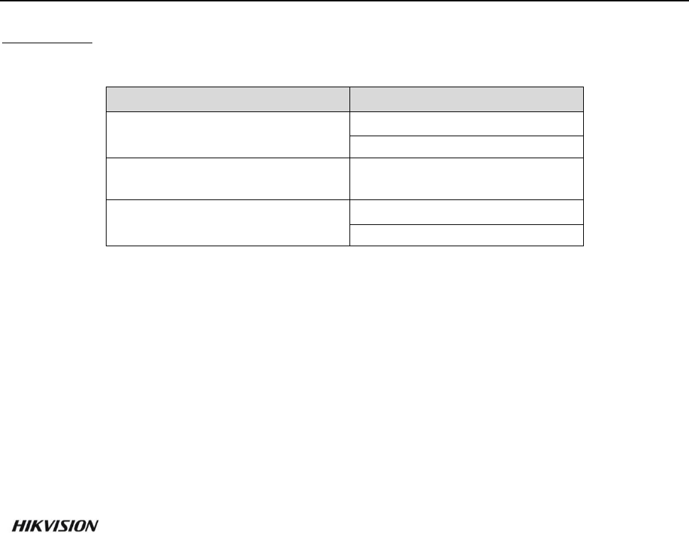
This manual is applied for face recognition terminal.
Series
Models
Face Recognition Terminal
(Without Fingerprint Module)
DS-K1T605M
DS-K1T605E
Face Recognition Terminal
(With Battery)
DS-K1T605MF-B
Face Recognition Terminal
(With Fingerprint Module)
DS-K1T605MF
DS-K1T605EF
Note: In the model, F represents the product contains fingerprint module. M and E represents the
product supports swiping Mifare card and EM card respectively. B represents the product contains
battery.
It includes instructions on how to use the Product. The software embodied in the Product is
governed by the user license agreement covering that Product.
About this Manual
This Manual is subject to domestic and international copyright protection. Hangzhou Hikvision
Digital Technology Co., Ltd. (“Hikvision”) reserves all rights to this manual. This manual cannot be
reproduced, changed, translated, or distributed, partially or wholly, by any means, without the
prior written permission of Hikvision.
Trademarks
and other Hikvision marks are the property of Hikvision and are registered
trademarks or the subject of applications for the same by Hikvision and/or its affiliates. Other
trademarks mentioned in this manual are the properties of their respective owners. No right of
license is given to use such trademarks without express permission.
Disclaimer
TO THE MAXIMUM EXTENT PERMITTED BY APPLICABLE LAW, HIKVISION MAKES NO WARRANTIES,
EXPRESS OR IMPLIED, INCLUDING WITHOUT LIMITATION THE IMPLIED WARRANTIES OF
MERCHANTABILITY AND FITNESS FOR A PARTICULAR PURPOSE, REGARDING THIS MANUAL.
HIKVISION DOES NOT WARRANT, GUARANTEE, OR MAKE ANY REPRESENTATIONS REGARDING THE
USE OF THE MANUAL, OR THE CORRECTNESS, ACCURACY, OR RELIABILITY OF INFORMATION
CONTAINED HEREIN. YOUR USE OF THIS MANUAL AND ANY RELIANCE ON THIS MANUAL SHALL BE
WHOLLY AT YOUR OWN RISK AND RESPONSIBILITY.
REGARDING TO THE PRODUCT WITH INTERNET ACCESS, THE USE OF PRODUCT SHALL BE WHOLLY
AT YOUR OWN RISKS. OUR COMPANY SHALL NOT TAKE ANY RESPONSIBILITIES FOR ABNORMAL
OPERATION, PRIVACY LEAKAGE OR OTHER DAMAGES RESULTING FROM CYBER ATTACK, HACKER
ATTACK, VIRUS INSPECTION, OR OTHER INTERNET SECURITY RISKS; HOWEVER, OUR COMPANY
WILL PROVIDE TIMELY TECHNICAL SUPPORT IF REQUIRED.
SURVEILLANCE LAWS VARY BY JURISDICTION. PLEASE CHECK ALL RELEVANT LAWS IN YOUR
JURISDICTION BEFORE USING THIS PRODUCT IN ORDER TO ENSURE THAT YOUR USE CONFORMS
THE APPLICABLE LAW. OUR COMPANY SHALL NOT BE LIABLE IN THE EVENT THAT THIS PRODUCT IS
USED WITH ILLEGITIMATE PURPOSES.

Face Recognition Terminal User Manual
ii
IN THE EVENT OF ANY CONFLICTS BETWEEN THIS MANUAL AND THE APPLICABLE LAW, THE LATER
PREVAILS.
Support
Should you have any questions, please do not hesitate to contact your local dealer.

Face Recognition Terminal User Manual
iii
Regulatory Information
FCC Information
Please take attention that changes or modification not expressly approved by the party responsible
for compliance could void the user’s authority to operate the equipment.
FCC compliance: This equipment has been tested and found to comply with the limits for a Class B
digital device, pursuant to part 15 of the FCC Rules. These limits are designed to provide
reasonable protection against harmful interference in a residential installation. This equipment
generates, uses and can radiate radio frequency energy and, if not installed and used in accordance
with the instructions, may cause harmful interference to radio communications. However, there is
no guarantee that interference will not occur in a particular installation. If this equipment does
cause harmful interference to radio or television reception, which can be determined by turning
the equipment off and on, the user is encouraged to try to correct the interference by one or more
of the following measures:
—Reorient or relocate the receiving antenna.
—Increase the separation between the equipment and receiver.
—Connect the equipment into an outlet on a circuit different from that to which the receiver is
connected.
—Consult the dealer or an experienced radio/TV technician for help.
This equipment should be installed and operated with a minimum distance 20cm between the
radiator and your body.
FCC Conditions
This device complies with part 15 of the FCC Rules. Operation is subject to the following two
conditions:
1. This device may not cause harmful interference.
2. This device must accept any interference received, including interference that may cause
undesired operation.
EU Conformity Statement
This product and - if applicable - the supplied accessories too are marked with "CE"
and comply therefore with the applicable harmonized European standards listed
under the RE Directive 2014/53/EU, the EMC Directive 2014/30/EU, the RoHS
Directive 2011/65/EU.
2012/19/EU (WEEE directive): Products marked with this symbol cannot be disposed
of as unsorted municipal waste in the European Union. For proper recycling, return
this product to your local supplier upon the purchase of equivalent new equipment,
or dispose of it at designated collection points. For more information see:
www.recyclethis.info
Face Recognition Terminal User Manual
iv
2006/66/EC (battery directive): This product contains a battery that cannot be
disposed of as unsorted municipal waste in the European Union. See the product
documentation for specific battery information. The battery is marked with this
symbol, which may include lettering to indicate cadmium (Cd), lead (Pb), or
mercury (Hg). For proper recycling, return the battery to your supplier or to a
designated collection point. For more information see: www.recyclethis.info
(1) 이 기기는 가정용으로 전자파적합등록을 한 기기로서 주거지역에서는 물론 모든 지역에서 사용할
수 있습니다。
(2) 당해 무선설비는 전파혼신 가능성이 있으므로 인명안전과 관련된 서비스는 할 수 없음。
Use only power supplies listed in the user instructions:
Model
Manufacturer
Standard
C2000IC12.0-24P-DE
MOSO Power Supply Technology Co., Ltd.
CEE
C2000IC12.0-24P-GB
MOSO Power Supply Technology Co., Ltd.
BS
Safety Instruction
These instructions are intended to ensure that user can use the product correctly to avoid danger
or property loss.
The precaution measure is divided into Warnings and Cautions:
Warnings: Neglecting any of the warnings may cause serious injury or death.
Cautions: Neglecting any of the cautions may cause injury or equipment damage.
Warnings
All the electronic operation should be strictly compliance with the electrical safety regulations,
fire prevention regulations and other related regulations in your local region.
Please use the power adapter, which is provided by normal company. The power consumption
cannot be less than the required value.
Do not connect several devices to one power adapter as adapter overload may cause over-heat
or fire hazard.
Please make sure that the power has been disconnected before you wire, install or dismantle
the device.
When the product is installed on wall or ceiling, the device shall be firmly fixed.
Warnings Follow
these safeguards to
prevent serious
injury or death.
Cautions Follow these
precautions to prevent
potential injury or
material damage.

Face Recognition Terminal User Manual
v
If smoke, odors or noise rise from the device, turn off the power at once and unplug the power
cable, and then please contact the service center.
If the product does not work properly, please contact your dealer or the nearest service center.
Never attempt to disassemble the device yourself. (We shall not assume any responsibility for
problems caused by unauthorized repair or maintenance.)
Cautions
Do not drop the device or subject it to physical shock, and do not expose it to high
electromagnetism radiation. Avoid the equipment installation on vibrations surface or places
subject to shock (ignorance can cause equipment damage).
Do not place the device in extremely hot (refer to the specification of the device for the detailed
operating temperature), cold, dusty or damp locations, and do not expose it to high
electromagnetic radiation.
The device cover for indoor use shall be kept from rain and moisture.
Exposing the equipment to direct sun light, low ventilation or heat source such as heater or
radiator is forbidden (ignorance can cause fire danger).
Do not aim the device at the sun or extra bright places. A blooming or smear may occur
otherwise (which is not a malfunction however), and affecting the endurance of sensor at the
same time.
Please use the provided glove when open up the device cover, avoid direct contact with the
device cover, because the acidic sweat of the fingers may erode the surface coating of the device
cover.
Please use a soft and dry cloth when clean inside and outside surfaces of the device cover, do
not use alkaline detergents.
Please keep all wrappers after unpack them for future use. In case of any failure occurred, you
need to return the device to the factory with the original wrapper. Transportation without the
original wrapper may result in damage on the device and lead to additional costs.
Improper use or replacement of the battery may result in hazard of explosion. Replace with the
same or equivalent type only. Dispose of used batteries according to the instructions provided by
the battery manufacturer.

Face Recognition Terminal User Manual
vi
Table of Contents
Chapter 1 Overview ................................................................................................................. 1
1.1 Introduction ......................................................................................................................... 1
1.2 Main Features ...................................................................................................................... 1
Chapter 2 Appearance ............................................................................................................. 3
Chapter 3 Installation .............................................................................................................. 5
3.1 Installing with Gang Box ....................................................................................................... 5
3.2 Installing without Gang Box ................................................................................................. 6
Chapter 4 Terminal Connection ................................................................................................ 8
Chapter 5 Basic Operation ..................................................................................................... 10
5.1 Activate Device ................................................................................................................... 10
5.1.1 Activating via Device ...................................................................................................... 10
5.1.2 Activating via SADP Software ......................................................................................... 11
5.1.3 Activating via Client Software ........................................................................................ 13
5.2 Login ................................................................................................................................... 15
5.3 General Parameters Settings .............................................................................................. 17
5.3.1 Communication Settings ................................................................................................ 17
5.3.2 System Settings .............................................................................................................. 21
5.3.3 Setting Time ................................................................................................................... 25
5.4 User Management .............................................................................................................. 26
5.4.1 Adding User .................................................................................................................... 26
5.4.2 Managing User ............................................................................................................... 30
5.5 Setting Access Control Parameters .................................................................................... 31
5.6 Other Managements .......................................................................................................... 33
5.6.1 Managing Data ............................................................................................................... 33
5.6.2 Managing Log Query ...................................................................................................... 34
5.6.3 Importing/Exporting Data .............................................................................................. 35
5.6.4 Testing ............................................................................................................................ 36
5.6.5 Viewing System Information .......................................................................................... 37
5.7 Authenticating Identity ...................................................................................................... 38
5.7.1 Authenticating via 1:1 Matching .................................................................................... 38
5.7.2 Authenticating via Other Types ...................................................................................... 39
Chapter 6 Client Operation .................................................................................................... 40
6.1 User Registration and Login ............................................................................................... 40
6.2 System Configuration ......................................................................................................... 41

Face Recognition Terminal User Manual
vii
6.3 Access Control Management ............................................................................................. 41
6.3.1 Adding Access Control Device ........................................................................................ 42
6.3.2 Viewing Device Status .................................................................................................... 57
6.3.3 Editing Basic Information ............................................................................................... 58
6.3.4 Network Settings ............................................................................................................ 59
6.3.5 Capture Settings ............................................................................................................. 61
6.3.6 RS-485 Settings ............................................................................................................... 62
6.3.7 Wiegand Settings ........................................................................................................... 63
6.3.8 Remote Configuration .................................................................................................... 64
6.4 Organization Management ................................................................................................ 74
6.4.1 Adding Organization ....................................................................................................... 74
6.4.2 Modifying and Deleting Organization ............................................................................ 74
6.5 Person Management .......................................................................................................... 75
6.5.1 Adding Person ................................................................................................................ 75
6.5.2 Managing Person............................................................................................................ 85
6.5.3 Issuing Card in Batch ...................................................................................................... 85
6.6 Schedule and Template ...................................................................................................... 87
6.6.1 Week Schedule ............................................................................................................... 88
6.6.2 Holiday Group ................................................................................................................ 89
6.6.3 Template ......................................................................................................................... 90
6.7 Permission Configuration ................................................................................................... 92
6.7.1 Adding Permission .......................................................................................................... 93
6.7.2 Applying Permission ....................................................................................................... 94
6.8 Advanced Functions ........................................................................................................... 95
6.8.1 Access Control Parameters ............................................................................................. 95
6.8.2 Card Reader Authentication ........................................................................................... 98
6.8.3 Multiple Authentication ................................................................................................. 99
6.8.4 Open Door with First Card ........................................................................................... 102
6.8.5 Anti-Passing Back ......................................................................................................... 104
6.9 Searching Access Control Event ....................................................................................... 105
6.9.1 Searching Local Access Control Event .......................................................................... 106
6.9.2 Searching Remote Access Control Event ...................................................................... 106
6.10 Access Control Event Configuration ................................................................................. 106
6.10.1 Access Control Event Linkage ................................................................................... 107
6.10.2 Event Card Linkage ................................................................................................... 108
6.10.3 Cross-Device Linkage ................................................................................................ 110

Face Recognition Terminal User Manual
viii
6.11 Door Status Management ................................................................................................ 111
6.11.1 Access Control Group Management ........................................................................ 111
6.11.2 Anti-control the Access Control Point (Door) ........................................................... 113
6.11.3 Status Duration Configuration ................................................................................. 114
6.11.4 Real-time Card Swiping Record ................................................................................ 116
6.11.5 Real-time Access Control Alarm ............................................................................... 116
6.12 Arming Control ................................................................................................................. 118
6.13 Time and Attendance ....................................................................................................... 118
6.13.1 Shift Schedule Management .................................................................................... 119
6.13.2 Attendance Handling ................................................................................................ 125
6.13.3 Advanced Settings .................................................................................................... 129
6.13.4 Attendance Statistics ................................................................................................ 133
Appendix A Tips for Scanning Fingerprint ............................................................................... 138
Appendix B Tips When Collecting/Comparing Face Picture ..................................................... 139
B.1 Positions (Recommended Distance:0.5m) ......................................................................... 139
B.2 Expression ........................................................................................................................ 139
B.3 Posture............................................................................................................................. 140
B.4 Size .................................................................................................................................. 140
Appendix C Relationship between Device Height, Person Height, and Standing Distance ......... 141
Appendix D Tips for Installation Environment ......................................................................... 142
Appendix E Dimension ........................................................................................................... 143

Face Recognition Terminal User Manual
1
Chapter 1 Overview
1.1 Introduction
DS-K1T605 series face recognition terminal is a kind of access control device for face
recognition, which is mainly applied in security access control systems, such as logistic
centers, airports, university campuses, alarm centrals, dwellings and so on.
The face recognition terminal supports 1:1 or 1:N matching mode. It also supports
authenticating via Mifare cards, EM cards, etc. according to different models.
Communications of TCP/IP, Wi-Fi, 3G/4G/GPRS (optional), RS-485 of Wiegand are also
supported. You can also import or export the data by using the USB disk.
1.2 Main Features
High performance processor with deep learning algorithm
Authenticates by swiping Mifare card or EM card according to different models
Live face detection: Only live face can be detected and authenticated
Max. 2000 face pictures and Max. 5000 fingerprints storage (Only models with F or FR support
fingerprint function)
Multiple authentication modes: face picture or fingerprint or card or password, fingerprint and
password, fingerprint and card, face picture and fingerprint, etc.
Note: Devices with models of DS-K1T605M/E and DS-K1T605M-B do support authenticating by
fingerprint.
1:1 and 1:N matching by comparing face pictures and fingerprints
Note: Devices with models of DS-K1T605M/E and DS-K1T605M-B do support authenticating by
fingerprint.
5-inch LCD touch screen to display operation interface, advertisements, etc.
Voice prompt and prompt sound output
Bi-spectrum cameras: one camera for receiving visible light and the other one for receiving
infrared light
Standard definition
Face picture recognition and face picture capture function
Saves captured pictures to the memory card with up to 32G storage
Supports TCP/IP, Wi-Fi , 3G/4G network (optional) communication, RS-485 communication and
Wiegand communication
Switches between input and output when communicating by Wiegand protocol; Supports
output card No. via Wiegand communication
Connects one external card reader via RS-485 communication

Face Recognition Terminal User Manual
2
Connects external access controller or Wiegand card reader via Wiegand communication
Connects secure door control unit to avoid the door opening when the terminal is destroyed
Supports import and export data via USB disk
Stand-alone operation
Supports anti-passback, multiple authentication, and open door with first card
Remotely controls via the iVMS-4200 client software
Power supply by lithium battery
Note: Only devices with models of DS-K1T605M-B support the function.
Hardware initialization
Face Recognition Terminal User Manual
3
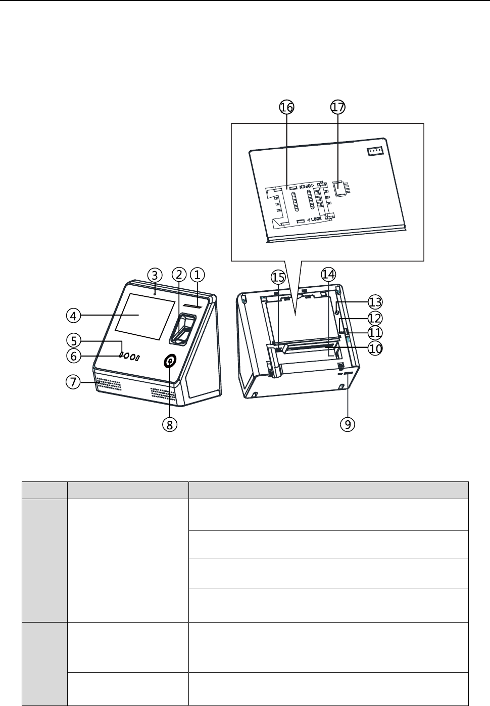
Chapter 2 Appearance
Refer to the following contents for detailed information of the face recognition terminal:
Table 1-1 Description of Face Recognition Terminal
No.
Name
Description
1
Indicator
Solid Red: Standby.
Flashing Red: Authentication failed.
Solid Green: Authentication completed.
Flashing Green: Authenticating (combined)...
2
Fingerprint Module +
Card Swiping Area
Scan fingerprint or swipe card.
Note: Only the device with the fingerprint module contains
this part.
Card Swiping Area
Swipe card within this area.
Note: Only the device without the fingerprint module

Face Recognition Terminal User Manual
4
contains this part.
3
Sensor
Detect the illumination intensity. When the environment is
too dark, the device will enable the supplement light
automatically.
4
Display Screen
5-inch LCD touch screen with the resolution of 800*480.
5
Supplement Light
Support visible light and IR light. Maximum distance for
supplement light: 1m.
6
Camera
Support bi-spectrum.
7
Loudspeaker
The part that the sound comes from.
8
Doorbell Button
Hold the button for 3s to power on and the device indicator
will light up.
After setting the power button function, hold the doorbell
button for 3s to power off.
Note: For details about setting the power button function, see
5.3.2 System Settings.
9
USB Interface
Plug in the USB disk and you can import or export the data.
10
Wiring Terminals
Connect to other external devices.
11
Memory Card Slot
Insert the memory card for saving the captured pictured.
12
Reset
While the device is powering on, hold the reset button and
the device will restore to the factory settings.
13
Tamper
When the tamper button is pressed down and the
tamper-proof function is enabled. If the device is pulled down,
the alarm will be triggered.
You should input the device activation password to dismiss
the alarm.
14
Network Interface
Connect to Ethernet.
15
Power Interface
Connect to power supply.
16
Micro SIM Card Slot
(Optional)
Insert SIM card.
17
Battery Connecter
Connect to battery.
Face Recognition Terminal User Manual
5
Chapter 3 Installation
Installation Environment:
Install the device indoors, at least 2 meters away from the light, and at least 3 meters away
from the window or the door.
Avoid backlight, direct and indirect sunlight.
Make sure the environment illumination is more than 100Lux.
Note: For details about installation environment, see Appendix D Tips for Installation Environment.
Installation Types: Wall mounting and base mounting.
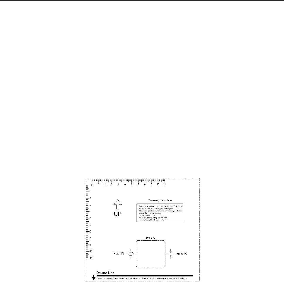
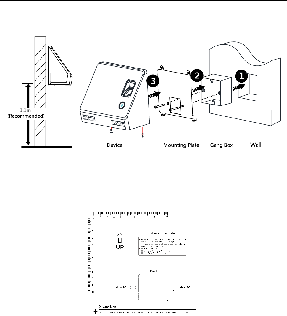
3.1 Installing with Gang Box
Before you start:
According to the datum on the mounting template, stick the mounting template on the wall or
other surface, 1.1 meters higher than the ground.
Steps:
1. Drill holes on the wall or other surface according to the mounting template and install the gang
box (80mm×80mm).
2. Use two supplied screws to secure the mounting plate on the gang box.
3. Remove the two screws at the bottom of the device.
4. Align the terminal with the mounting plate and buckle them together.
5. Use a hex wrench to fasten the two screws at the bottom.
Notes:
The installation height here is the recommended height. You can change it according to your
actual needs.
You can also install the device on the wall or otoher places without the gang box. For details,
see 3.2 Installing without Gang Box.
Face Recognition Terminal User Manual
6
For easy installation, drill holes on mounting surface according to the supplied mounting
template.
3.2 Installing without Gang Box
Before you start:
According to the basline on the mounting template, stick the mounting template on the wall or
other surface, 1.1 meters higher than the ground.
Steps:
1. Drill holes on the wall or other surface according to the mounting template.
2. Insert the screw sockets of the setscrews in the drilled holes.
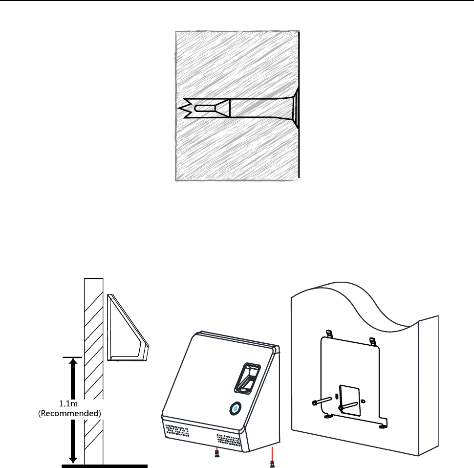
Face Recognition Terminal User Manual
7
3. Align the two holes to the mounting plate with the drilled holes.
4. Fix and fasten the screws in the sockets on the wall or other surface.
5. Remove the two screws at the bottom of the device.
6. Align the terminal with the mounting plate and buckle them together.
7. Use a hex wrench to fasten the two screws at the bottom.
Face Recognition Terminal User Manual
8
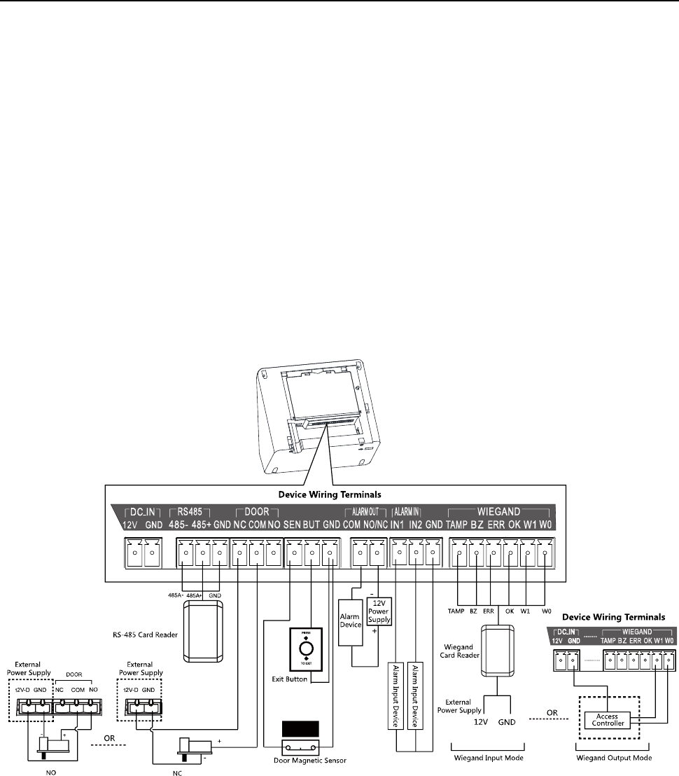
Chapter 4 Terminal Connection
You can connect the RS-485 terminal with the RS-485 card reader, connect the DOOR terminal with
the door lock, connect the SEN/BUT/GND terminal with the exit button, connect the ALARM
OUT/ALRM IN terminal with the alarm output/input devices, and connect the WIEGAND terminal
with the Wiegand card reader or the access controller. You can also connect the DS_IN can with
the power supply.
If connect the WIEGAND terminal with the access controller, the face recognition terminal can
transmit the authentication information to the access controller and the access controller can
judge whether to open the door or not.
The wiring diagram is as follows:
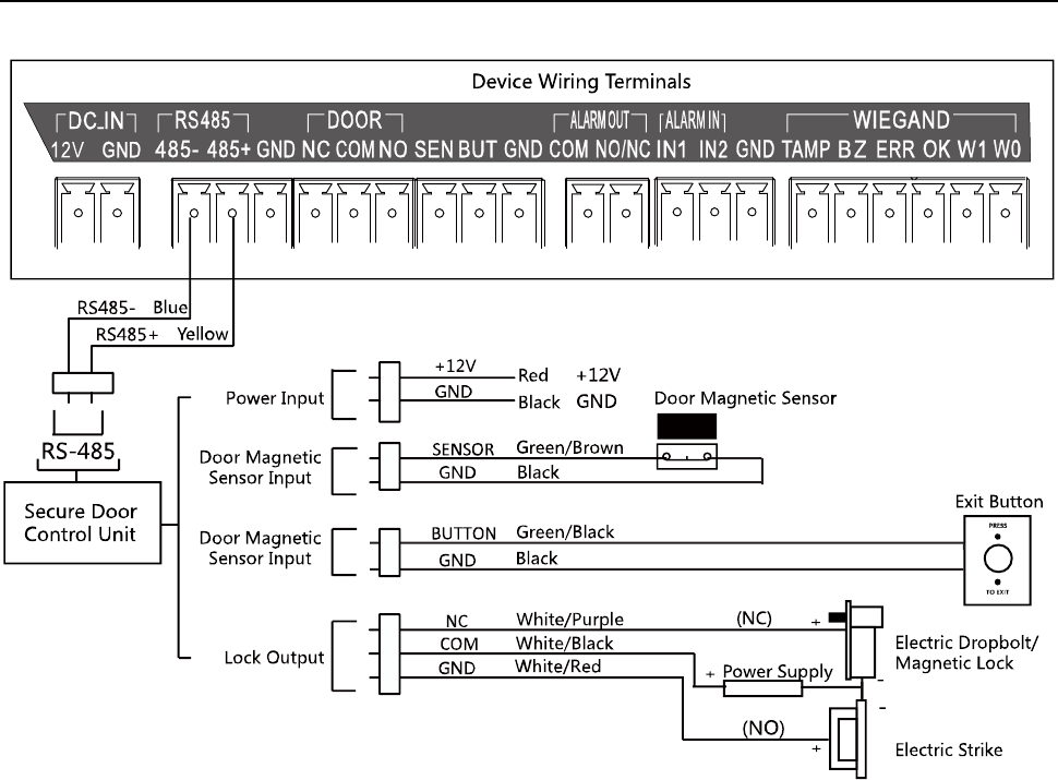
You can also connect the terminal with the seucure door control unit. The wiring diagram is as
follows:
Face Recognition Terminal User Manual
9
Face Recognition Terminal User Manual
10
Chapter 5 Basic Operation
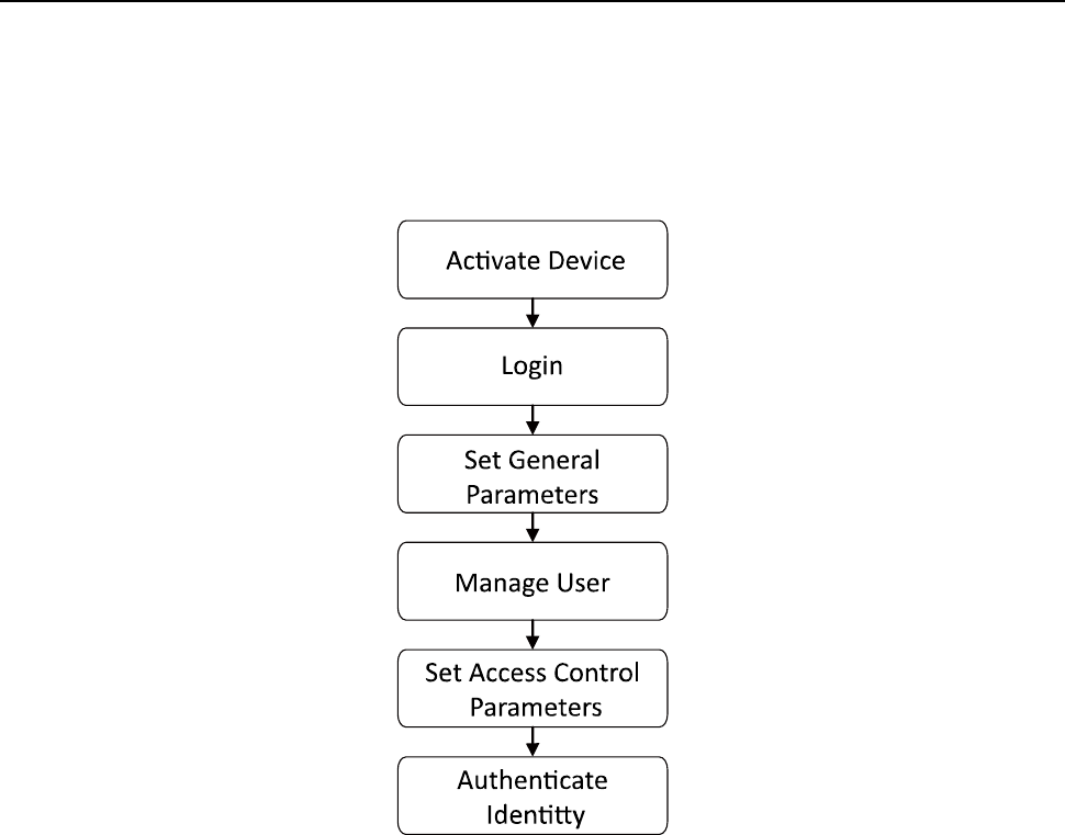
The suggested working flow is as follows:
5.1 Activate Device
Purpose:
You are required to activate the terminal first before using it.
Activation via device, activation via SADP, and activation via client software are supported.
The default values of the control terminal are as follows.
The default IP address: 192.0.0.64.
The default port No.: 8000.
The default user name: admin.
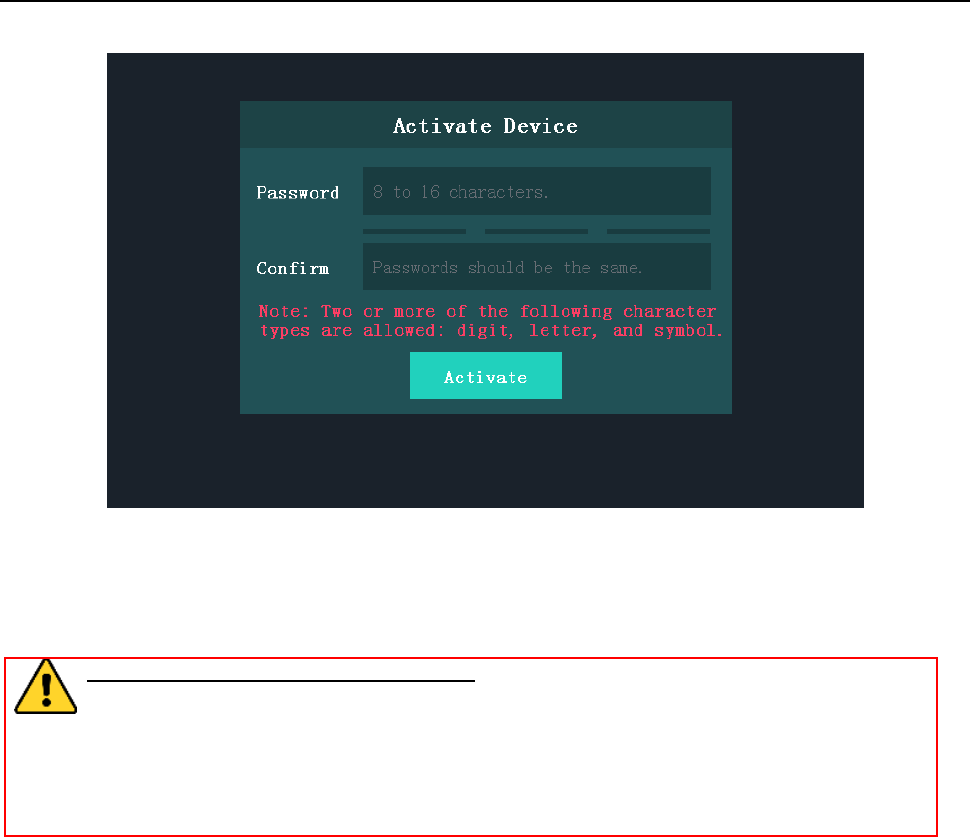
5.1.1 Activating via Device
If the device is not activated, you can activate the device after it is powering on.
Face Recognition Terminal User Manual
11
Steps:
1. Tap the Password field and create a password.
2. Tap the Confirm field and input the password again.
3. Tap Activate and the device will be activated.
STRONG PASSWORD RECOMMENDED– We highly recommend you create a strong
password of your own choosing (using a minimum of 8 characters, including upper case
letters, lower case letters, numbers, and special characters) in order to increase the
security of your product. And we recommend you reset your password regularly,
especially in the high security system, resetting the password monthly or weekly can
better protect your product.
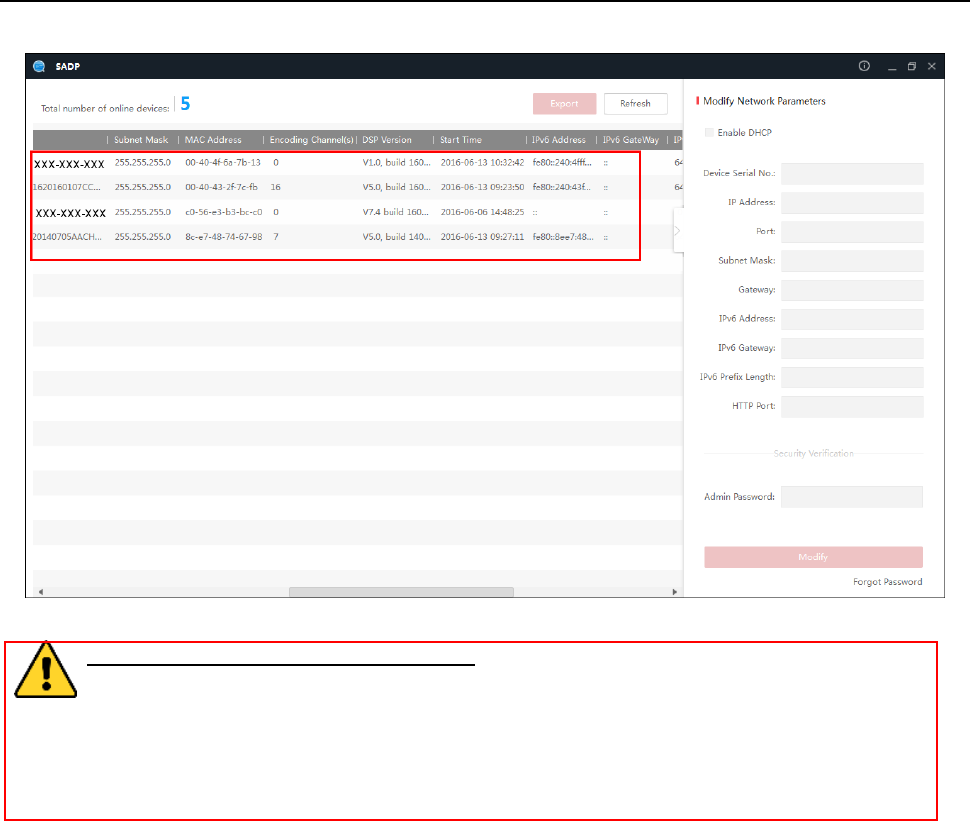
5.1.2 Activating via SADP Software
Purpose:
SADP software is used for detecting the online device, activating the device, and resetting the
password.
Get the SADP software from the supplied disk or the official website, and install the SADP
according to the prompts. Follow the steps to activate the device.
Steps:
1. Run the SADP software to search the online devices.
2. Check the device status from the device list, and select an inactive device.
Face Recognition Terminal User Manual
12
3. Create a password in the password field, and confirm the password.
STRONG PASSWORD RECOMMENDED– We highly recommend you create a strong
password of your own choosing (using a minimum of 8 characters, including upper case
letters, lower case letters, numbers, and special characters) in order to increase the
security of your product. And we recommend you reset your password regularly,
especially in the high security system, resetting the password monthly or weekly can
better protect your product.
4. Click Activate to activate the device.
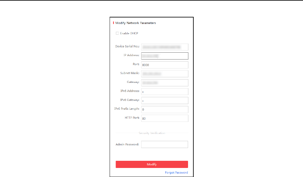
5. Check the activated device. You can change the device IP address to the same network
segment with your computer by either editing the IP address manually or checking the Enable
DHCP checkbox.
Face Recognition Terminal User Manual
13
6. Input the password and click Modify to save the IP address.
5.1.3 Activating via Client Software
Purpose:
The client software is versatile video management software for multiple kinds of devices.
Get the client software from the supplied disk or the official website, and install the software
according to the prompts. Follow the steps to activate the control panel.
Steps:
1. Run the client software and the control panel of the software pops up, as shown in the figure
below.
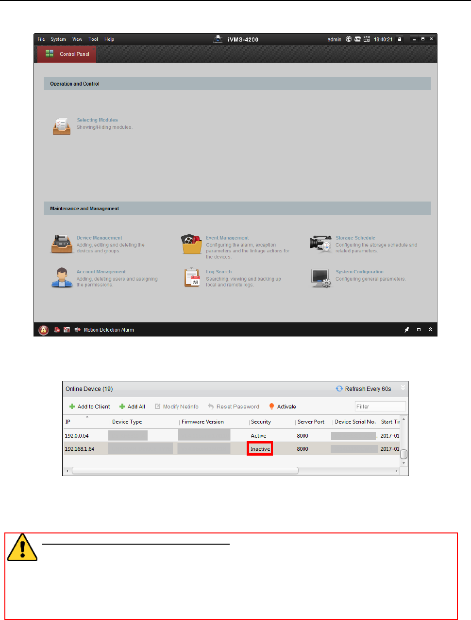
Face Recognition Terminal User Manual
14
2. Click Device Management to enter the Device Management interface.
3. Check the device status from the device list, and select an inactive device.
4. Check the device status from the device list, and select an inactive device.
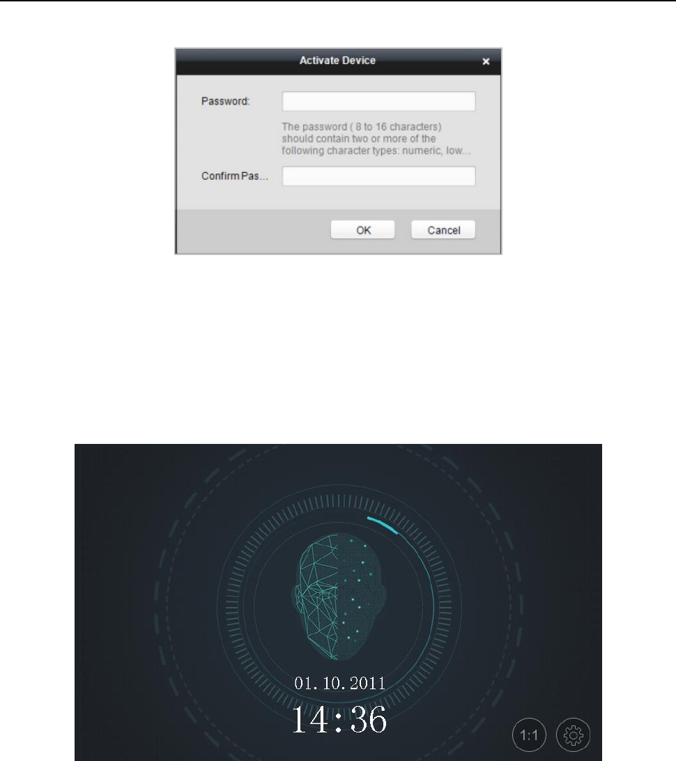
5. Click Activate to pop up the Activation interface.
6. In the pop-up window, create a password in the password field, and confirm the password.
STRONG PASSWORD RECOMMENDED– We highly recommend you create a strong
password of your own choosing (using a minimum of 8 characters, including upper
case letters, lower case letters, numbers, and special characters) in order to increase
the security of your product. And we recommend you reset your password regularly,
especially in the high security system, resetting the password monthly or weekly can
better protect your product.
Face Recognition Terminal User Manual
15
7. Click OK button to start activation.
8. Click the Modify Netinfor button to pop up the Network Parameter Modification interface.
9. Change the device IP address to the same network segment as your computer by modifying
the IP address manually.
10. Input the password and click OK to save the settings.
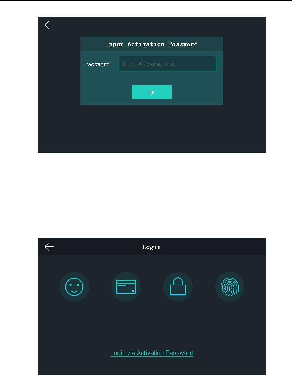
After activation, you will enter the initial page:
5.2 Login
Option 1
If it is the first time to login, follow the steps below to login.
Steps:
1. Tap the settings icon at the lower right corner of the initial page to enter the Input Password
page.
Face Recognition Terminal User Manual
16
2. Tap the Password field and input the device activation password.
3. Tap OK to enter the initial page.
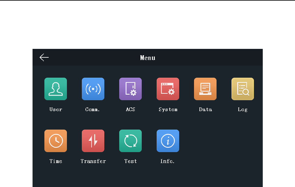
Option 2
If you have set the administrator on the User Management page, follow the steps below to login.
Steps:
1. Tap the settings icon at the lower right corner of the initial page to enter the Login page.
2. Select the login type.
3. Authenticate permissions to enter the home page.
Tap one of the four authentication modes on the upper side of the page and authenticate
permissions.
Face Recognition Terminal User Manual
17
Or tap Login via Activation Password and input the device activation password to enter the
home page.
The home page is shown as below:
Notes:
The device will be locked for 30 minutes after 5 failed password attempts.
The supported authentication modes are as follows:
Face picture or fingerprint, or card or password, fingerprint and password, fingerprint and
card, face picture and password, face picture and card, card and password, fingerprint, face
picture, employee ID and password, card, fingerprint or card, fingerprint or password, card
or password, employee ID and fingerprint, fingerprint and card and password, employee ID
and fingerprint and password, face picture and fingerprint and card, face picture and
password and fingerprint, employee ID and face picture.
The device with the model of DS-K1T605E/M/S or DS-K1T605M-B does not support the
fingerprint authentication mode.
For details about setting the administrator authentication mode, see 5.4.1 Adding User.
5.3 General Parameters Settings
5.3.1 Communication Settings
Purpose:
You can set the network parameters, the Wi-Fi parameter, the RS-485 parameters, and the
Wiegand parameters on the communication settings page.
Tap Comm. (Communication Settings) on the Home page to enter the Communication Settings
page.
Face Recognition Terminal User Manual
18
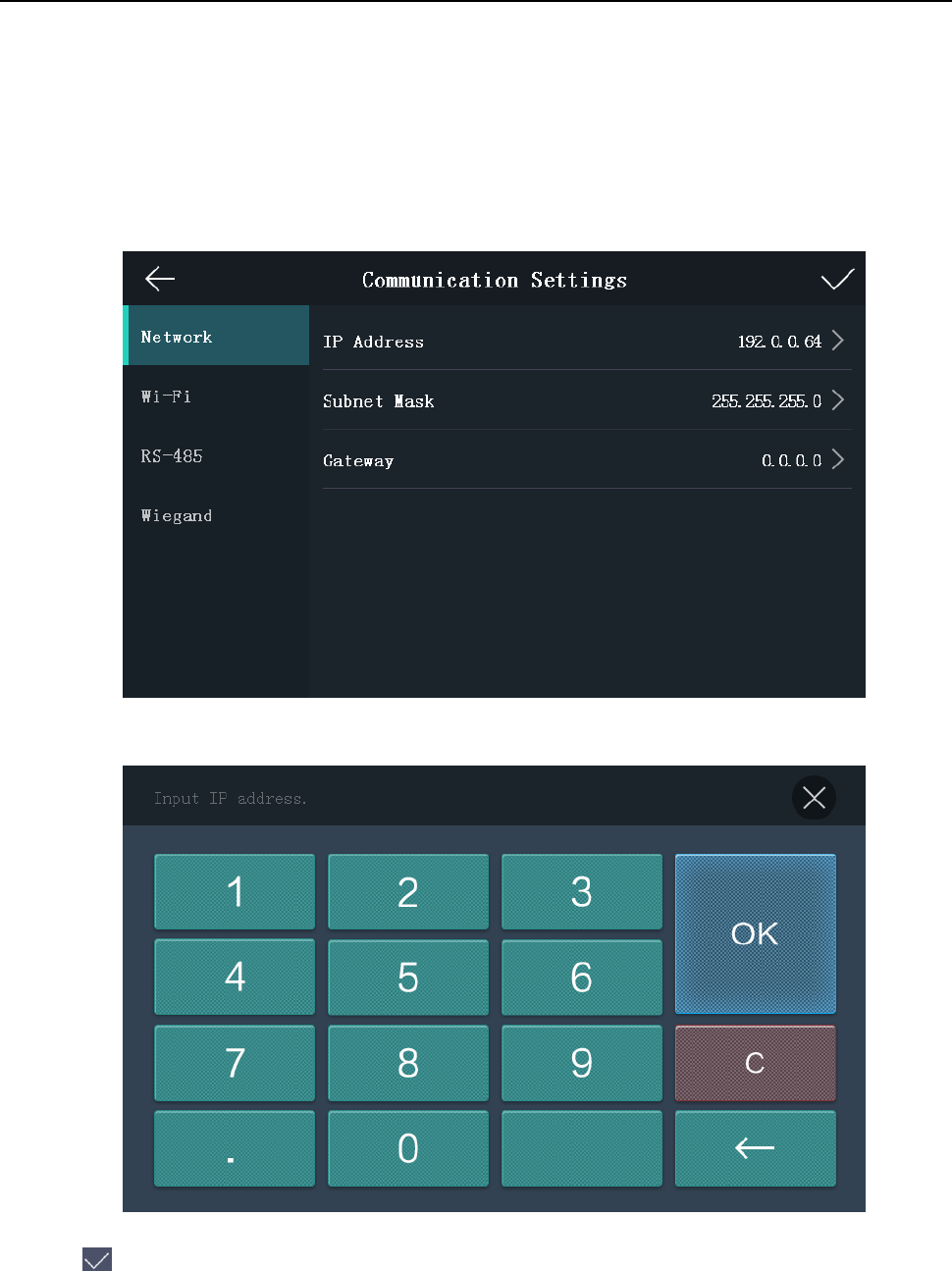
Setting Network Parameters
Purpose:
You can set the device network parameters, including the IP address, the subnet mask, and the
gateway.
Steps:
1. On the Communication Settings page, tap Network to enter the Network tab.
2. Tap IP Address, Subnet Mask, or Gateway and input the parameters.
3. Tap OK to save the settings.
Note: The device’s IP address and the computer IP address should be in the same LAN.
4. Tap to save the network parameters and go back to the Home page.
Setting Wi-Fi Parameters
Purpose:
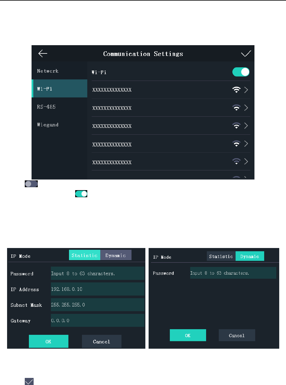
Face Recognition Terminal User Manual
19
You can enable the Wi-Fi function and set the Wi-Fi related parameters.
Steps:
1. On the Communication Settings page, tap Wi-Fi to enter the Wi-Fi tab.
2. Tap to enable the Wi-Fi function.
The icon will turns to and all searched Wi-Fi will be listed in the Wi-Fi list.
3. Select a Wi-Fi in the list to enter the Wi-Fi parameters settings page.
4. Select an IP mode.
If selecting Statistic, you should input the Wi-Fi password, IP address, subnet mask and
gateway.
If selecting Dynamic, you should input the Wi-Fi password.
Note: Numbers, upper case letters, lower case letters, and special characters are allowed in the
Wi-Fi password.
5. Tap OK to save the settings and go back to the Wi-Fi tab.
6. Tap to save the Wi-Fi parameters and go back to the Home page.
Face Recognition Terminal User Manual
20
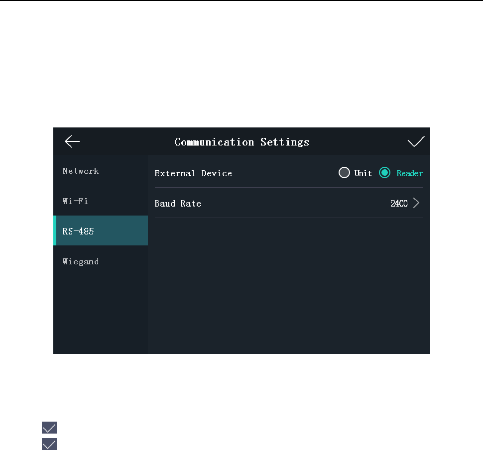
Setting RS-485 Parameters
Purpose:
The face recognition terminal can connect external secure door control unit or card reader via the
RS-485 terminal.
Steps:
1. On the Communication Settings page, tap RS-485 to enter the RS-485 tab.
2. Select an external device according to your actual needs.
Note: Unit represents the secure door control unit and Reader represents the card reader.
3. Tap Baud Rate to enter the Baud Rate page.
4. Select a baud rate for connecting external device via RS-485 protocol.
5. Tap to save the selected baud rate and go back to the RS-485 tab.
6. Tap to save the RS-485 parameters and go back to the Home page.
Note: If you change the external device, and after you save the device parameters, the device
will reboot automatically.
Setting Wiegand Parameters
Purpose:
You can set the Wiegand transmission direction and the Wiegand mode.
Steps:
1. On the Communication Settings page, tap Wiegand to enter the Wiegand tab.
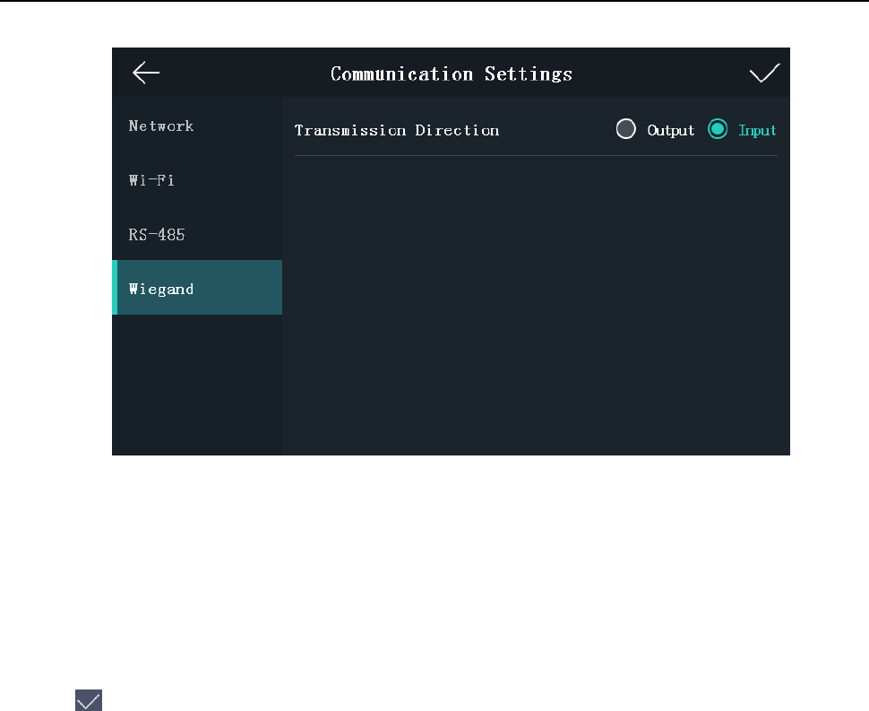
Face Recognition Terminal User Manual
21
2. Select the transmission direction and its mode.
Transmission Direction:
Output: A face recognition terminal can connect an external access controller. And the two
devices will transmit the card No. via Wiegand 26 or Wiegand 34 mode.
Input: A face recognition terminal can connect a Wiegand card reader. And there is no need
to set the Wiegand mode.
Mode:
You can select either Wiegand 26 or Wiegand 34. By default, the system selects Wiegand 34.
3. Tap to save the Wiegand parameters and go back to the Home page.
Note: If you change the Wiegand mode and save the parameters, the device will reboot
automatically.
5.3.2 System Settings
Purpose:
On the System Settings page, you can set the system basic parameters, set the face picture
parameters, and upgrade the firmware.
On the Home page, tap System (System Settings) to enter the System Settings page.
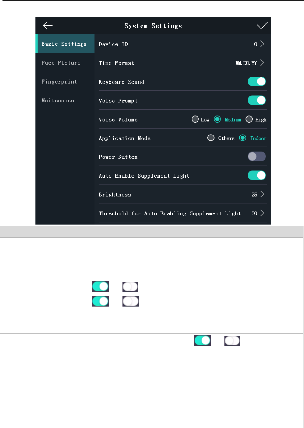
Setting Basic Parameters
Purpose:
You can set the device ID, time format, keyboard sound, voice prompt, voice volume, application
mode, power button, auto enable supplement light, brightness, and Threshold for Auto Enabling
Supplement Light.
Face Recognition Terminal User Manual
22
Parameter
Description
Device ID
Set the face recognition terminal’s device ID No.
Time Format
You can select one of the following formats: MM/DD/YYYY,
MM.DD.YYYY, DD-MM-YYYY, DD/MM/YYYY, DD.MM.YYYY, YYYYMMDD,
YY-MM-DD, YY/MM/DD, and MM-DD-YYYY.
Keyboard Sound
Tap or to disable or enable the keyboard sound.
Voice Prompt
Tap or to disable or enable the voice promt.
Voice Volume
You can adjust the voice volume to Low, Medium or High.
Application Mode
You can select either others or indoor according to actual environment.
Power Button
Namely, it is the doorbell button. Tap or to disable or
enable the function
If enabling the function, hold the doorbell button for 3s to power off.
If disabling the function, the doorbell button will not contain the
powering off function.
Notes:
Only the device containing –B in the model supports the function.
If you power off the device via this button, you should hold the
button to power on for the next time.
Face Recognition Terminal User Manual
23
Auto Enable
Supplement Light
If enabling the function, when it is too dark, the supplement light will be
turned on automatically.
If disabling the function, the supplement light will be on all the time.
Brightness
You can set the supplement light’s brightness. The brightness ranges
from 0 to 100.
0 refers to turning off the light. 1 refers to the darkest light, and 100
refers to the brightest light.
Threshold for Auto
Enabling Supplement
Light
When the auto enable supplement light function is enabled, you can set
the illumination threshold. When the illumination is lower than the
configured threshold, the supplement light will turned on automatically.
Notes:
The device ID should be numbers and should range from 0 to 255.
If the device is not activated, the power button is enabled by default; after the device is
activated, the power button function will be disabled. You should enable the function
manually.
We suggest you to disable the function in the scenario of access control system.
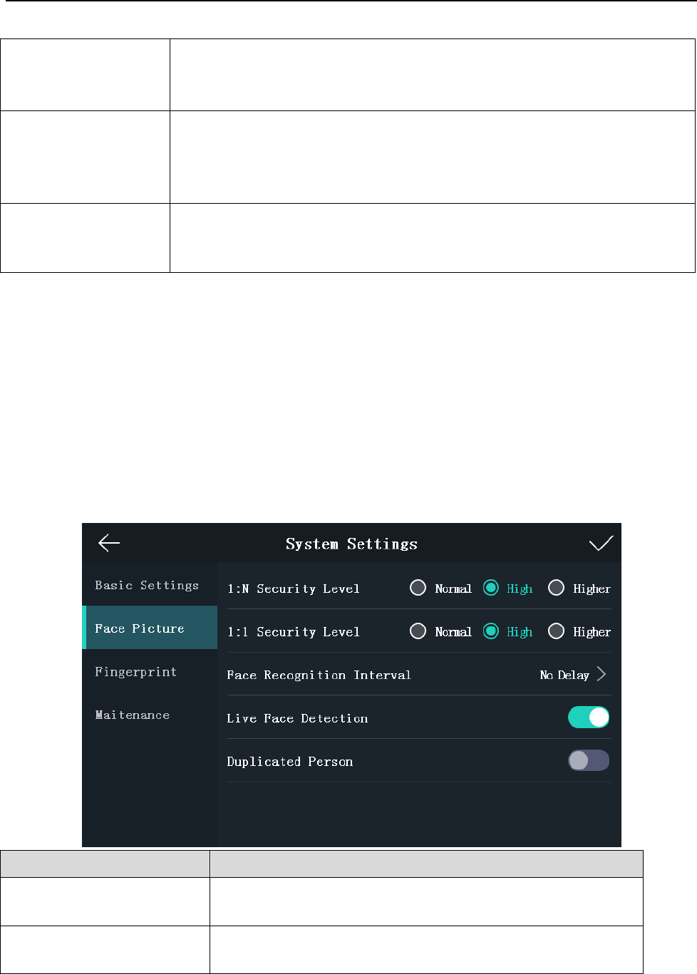
Setting Face Picture Parameters
Purpose:
You can set the face picture 1:N match threshold, 1:1 match threshold, face recognition interval,
live face detection, and duplicated person.
Parameter
Description
1:N Security Level
Set the matching security level when authenticating via 1:N
matching mode.
1:1 Security Level
Set the matching security level when authenticating via 1:1
matching mode.
Face Recognition Terminal User Manual
24
Face Recognition Interval
The time interval between two continuous face
recognitions when authenticating. By default, it is 2s.
Note: You can input the number from 1 to 10 or 255. 255
refers to infinite.
Live Face Detection
Enable or disable the live face detection function. If
enabling the function, the device can recognize whether
the person is a live one or not.
Duplicated Person
If enabling the function, the system will compare the
adding face picture with all pictures in the database when
adding a user. If the person already exists in the database,
the system will remind you.
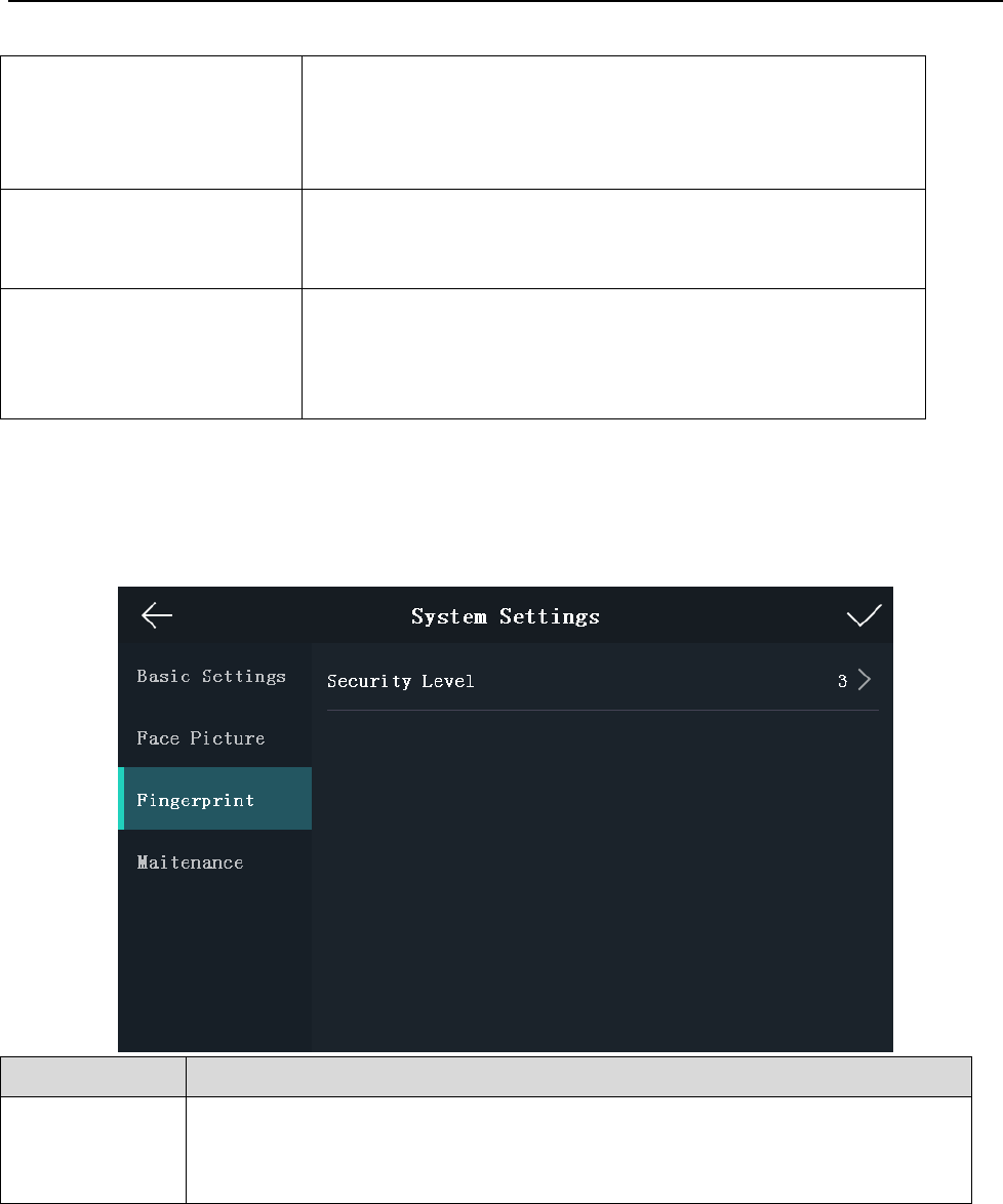
Setting Fingerprint Parameters
Purpose:
You can set the fingerprint security level in this section.
Note: The device with the model of DS-K1T605M-L does not support the fingerprint function.
Parameter
Description
Security Level :
You can set the fingerprint security level.
The higher is the security level, the lower is the false acceptance rate (FAR).
The higher is the security level, the higher is the false rejection rate (FRR).
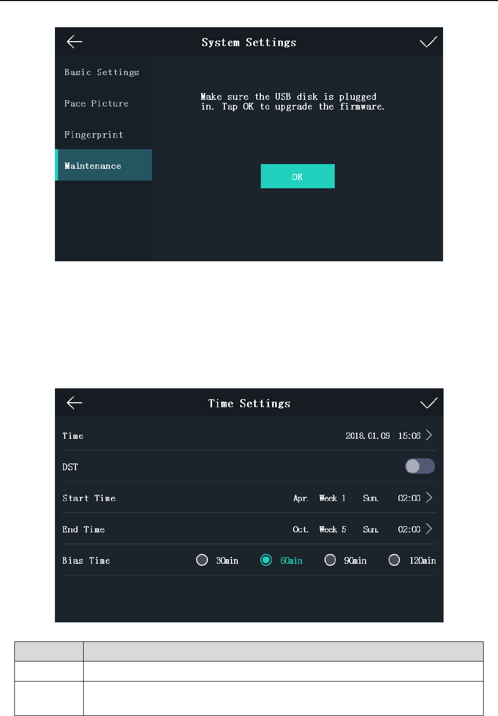
Upgrading Firmware
On the Maintenance page, plug in the USB disk and tap OK. The device will automatically read the
upgrading file and upgrade the firmware.
Note:
The upgrading file should be in the root directory.
The upgrading file name should be digicap.dav.
Face Recognition Terminal User Manual
25
5.3.3 Setting Time
Purpose:
You can set the device time and the DST in this section.
Steps:
1. Tap Time (Time Settings) on the Home page to enter the Time Settings page.
2. Edit the time parameters.
Parameter
Description
Time:
Set the time which will be displayed on the device screen.
DST:
Enable or disable the DST function. If enabling the DST function, you can set
the DST start time, end time, and the bias time.
Face Recognition Terminal User Manual
26
Start Time: Set the DST start time.
End Time: Set the DST end time.
Bias Time: Set the DST bias time when the DST starts.
3. Tap to save the settings and go back to the Home page.
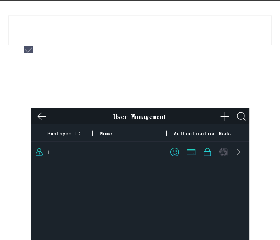
5.4 User Management
Purpose:
On the user management interface, you can add, edit, delete and search the user.
Tap User on the Home page to enter the User Management page.
5.4.1 Adding User
Purpose:
On the Add User page, you can add users, including the employee No., name, card No. You can also
link the fingerprint, the face picture to the user, or set password, authentication mode, schedule
template, administrator permission for the user.
Notes:
Up to 5000 users can be added.
The device with the model of DS-K1T600M-L does not support the fingerprint function.
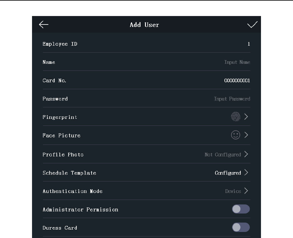
Steps:
1. On the User Management page, tap + to enter the Add User page.
Face Recognition Terminal User Manual
27
2. Tap the Employee ID. field and edit the employee ID.
Notes:
The employee ID should be between 1 and 99999999. The employee ID should not start with 0
and should not be duplicated.
3. Tap the Name field and input the user name on the soft keyboard.
Notes:
Numbers, upper case letters, lower case letters, and special characters are allowed in the
user name.
Up to 32 characters are allowed in the user name.
4. Tap the Card field and input the card No.
Option 1: Input the card No. manually.
Option2: Swipe the card over the card swiping area to get the card No.
Notes:
The card No. cannot be empty.
Up to 20 characters are allowed in the card No.
By default, the card No. contains 10 characters. The system will use 0 to supplement the
10-character-card No. For example, 5 and 0000000005 are two different card No.
The card No. cannot be duplicated.
Face Recognition Terminal User Manual
28
5. Tap the Password field and create a password and confirm the password.
Note:
Only numbers are allowed in the password.
Up to 8 characters are allowed in the password.
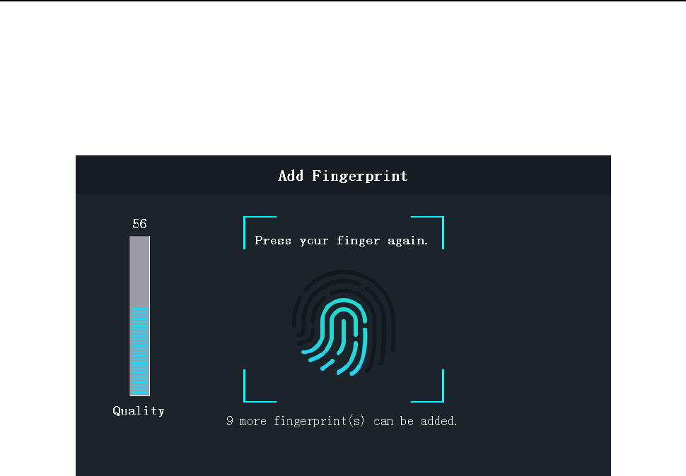
6. Tap the Fingerprint field to enter the Add Fingerprint page.
Follow the steps below to add fingerprint.
1) Place your finger on the fingerprint module.
2) Follow the instructions on the screen to record the fingerprint.
3) After adding the fingerprint completely, tap Yes in the pop-up dialog to save the fingerprint
and continue to add another fingerprint.
Or tap No to save the fingerprint and go back to the Add User page.
Notes:
The same fingerprint cannot be repeatedly added.
Up to 10 fingerprints can be added for one user.
You can also use the client software or the fingerprint recorder to record fingerprints.
For details about the instructions of scanning fingerprints, see Appendix A Tips for
Scanning Fingerprint.
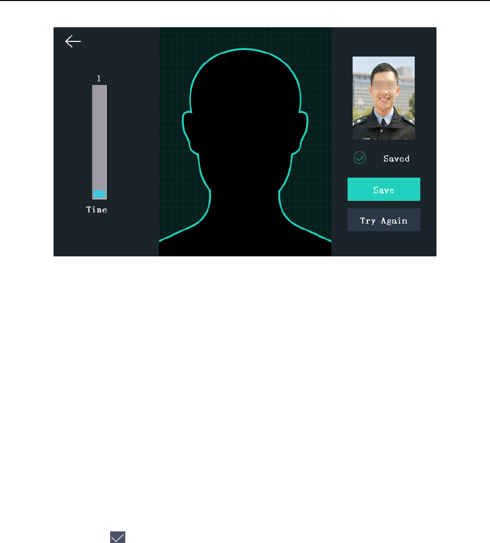
7. Tap the Face Picture field to enter the face picture adding page.
Face Recognition Terminal User Manual
29
Follow the steps below to add the user’s face picture.
1) Position your face looking at the camera.
Note: Make sure your face picture is in the face picture outline when adding the face
picture.
After completely adding the face picture, a captured face picture will be displayed at the
upper right corner of the page.
Notes:
Make sure the captured face picture is in good quality and is accurate.
For details about the instructions of adding face pictures, see Appendix B Tips When
Collecting/Comparing Face Picture.
2) Tap Save to save the face picture.
Or tap Try Again and adjust your face position to add the face picture again.
Note: The maximum duration for adding a face picture is 15s. You can check the remaining
time for adding a face picture on the left of the page.
8. Tap the Profile Photo field and you can view the captured picture when adding the face
picture.
9. Tap the Schedule Template field to enter the Schedule Template page. Select a schedule
template and tap to save the settings.
Note: For details about setting the schedule template, see 6.6 Schedule and Template. After
applying the schedule tem plate from the client software to the devce, you can select the
corresponding schedule template
10. Tap Authentication Mode to enter the Authentication Mode page. Select Device or Custom as
the authentication mode.
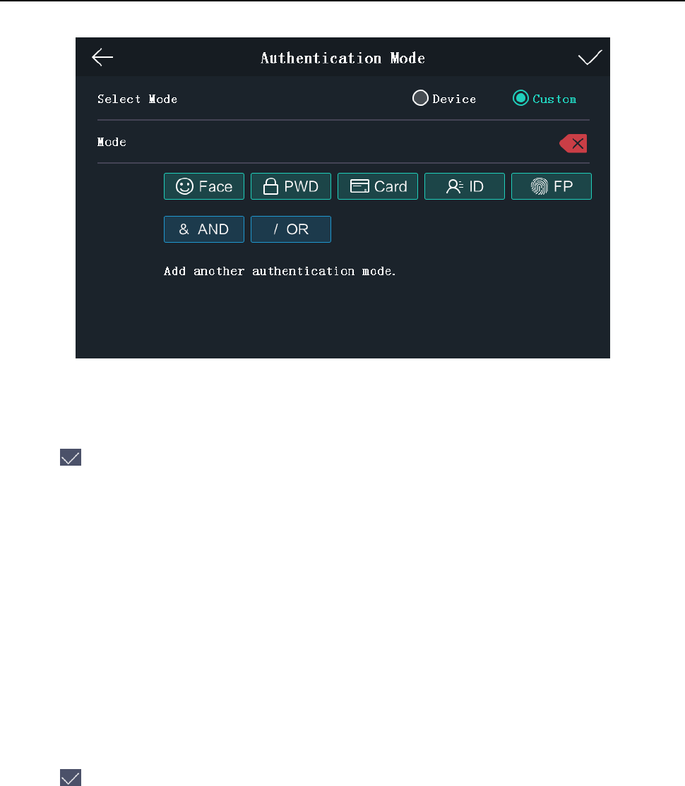
Face Recognition Terminal User Manual
30
Device: If you want to seelct device mode, you should set the terminal authentication mode in
Acess Control Settings page first. For details see 5.5 Setting Access Control Parameters.
Custom: You can combine different authentication modes together according to your actual
needs.
Tap to save the settings.
Note: The device with the models of DS-K1T605E/M/S and DS-K1T605M-B does not support
the fingerprint function.
11. Enable or disable the Administrator Permission function.
Note: You can only operate the function on the device.
Enable Administrator
Permission:
The user is the administrator. Except for the normal attendance
function, the user can also enter the Home page to operate after
authenticating the permission.
Disable Administrator
Permission:
The User is the normal user. The user can only take attendance on
the initial page.
12. Enable or disable the Duress Card function.
When the function is enabled, the user’s card will be the duress card. When the user
authenticates by swiping this duress card, the device will upload an duress card event to the
client software.
13. Tap to save the user parameters and go back to the Home page.
5.4.2 Managing User
Searching User
Purpose:
You can search the user in the list according to the employee ID, the card No., or the user name.
Steps:
Face Recognition Terminal User Manual
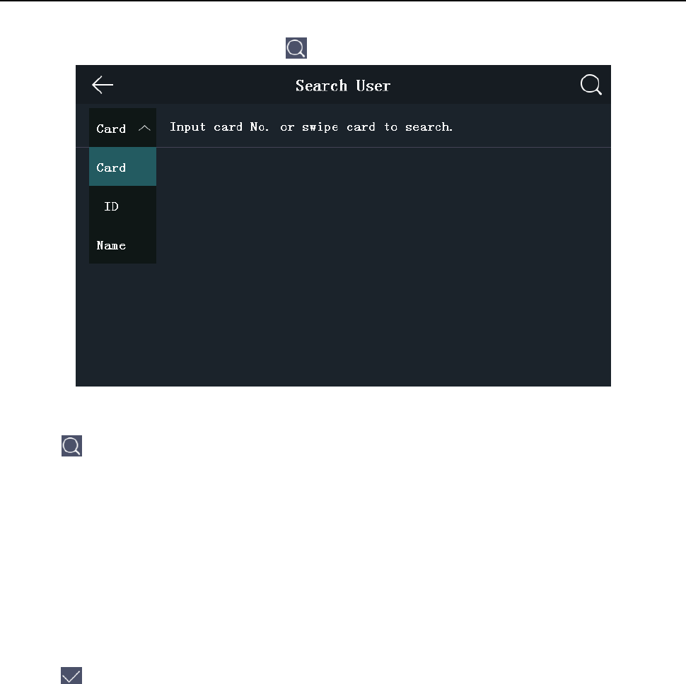
31
1. On the User Management page, Tap to enter the Search User page.
2. Tap Card on the left of the page and select a search type from the drop-down list.
3. Tap the input box and input the employee ID, the card No., or the user name for search.
4. Tap to start search.
The searching result will be displayed in the list below.
Editing User
Purpose:
You can edit the added user information by following the steps in this section.
Steps:
1. In the User Management page, tap the user that needs to be edited to enter the Edit User
page.
2. Refer to the parameters’ instructions in Section 5.4.1 Adding User to edit the user information.
3. Tap to save the settings and go back to the User Management page.
Note: The employee ID cannot be edited.
5.5 Setting Access Control Parameters
Purpose:
You can set the access control permissions, including the functions of authentication mode, door
magnetic sensor, anti-passback, lock action time, door-open timeout alarm, and authentication
times exceeds alarm.
Steps:
1. On the Home page, tap ACS (Access Control Settings) to enter the Access Control Settings
page.
Face Recognition Terminal User Manual
32
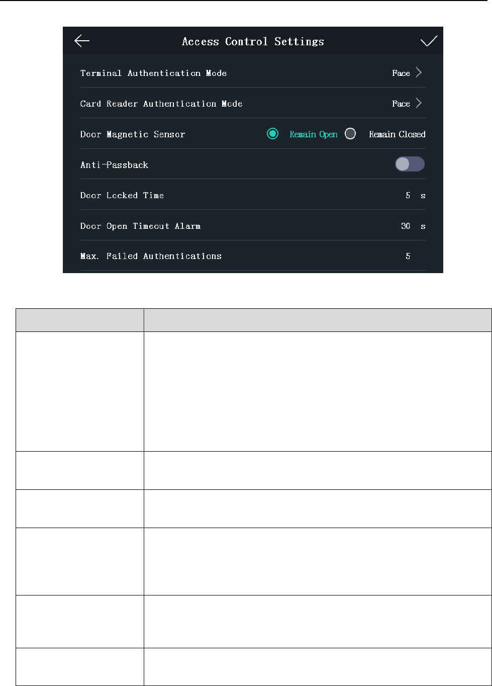
2. Edit the access control parameters.
The available parameters descriptions are as follows:
Parameter
Description
Terminal
Authentication Mode
Select the face recognition terminal’s authentication mode. You can
also customize the authentication mode.
Notes:
The device with the model of DS-K1T605E/M/S and
DS_K1T605M-B do not support the fingerprint function.
If you require a higher security level, do not use single
authentication mode.
Card Reader
Authentication Mode
Select the card reader’s authentication mode.
Door Magnetic Sensor
You can select Remain Open or Remain Closed according to your
actual needs. By default, it is Remain Closed.
Anti-Passback
When enabling the anti-passback function, you should set the
anti-password path in the iVMS-4200 Client Software. The person
should authenticate according to the configured path. Or the
authentication will be failed.
Door Locked Time
Set the door unlocking duration. If the door is not opened for the set
time, the door will be locked. Available door locked time range: 1 to
255s.
Door Open Timeout
Alarm
The alarm can be triggered if the door has not been closed.
Available range: 0 to 255s.
Face Recognition Terminal User Manual
33
Max. Failed
Authentications
Set the maximum authentication times. If you failed to authenticate
for the set times, the alarm will be triggered.
Available range: 1 to 10.
3. Tap to save the settings.
5.6 Other Managements
5.6.1 Managing Data
Purpose:
On the Data Management page, you can delete all events, delete user data, delete all data, clear
permission, delete captured pictures, restore to factory settings, or restore to default settings.
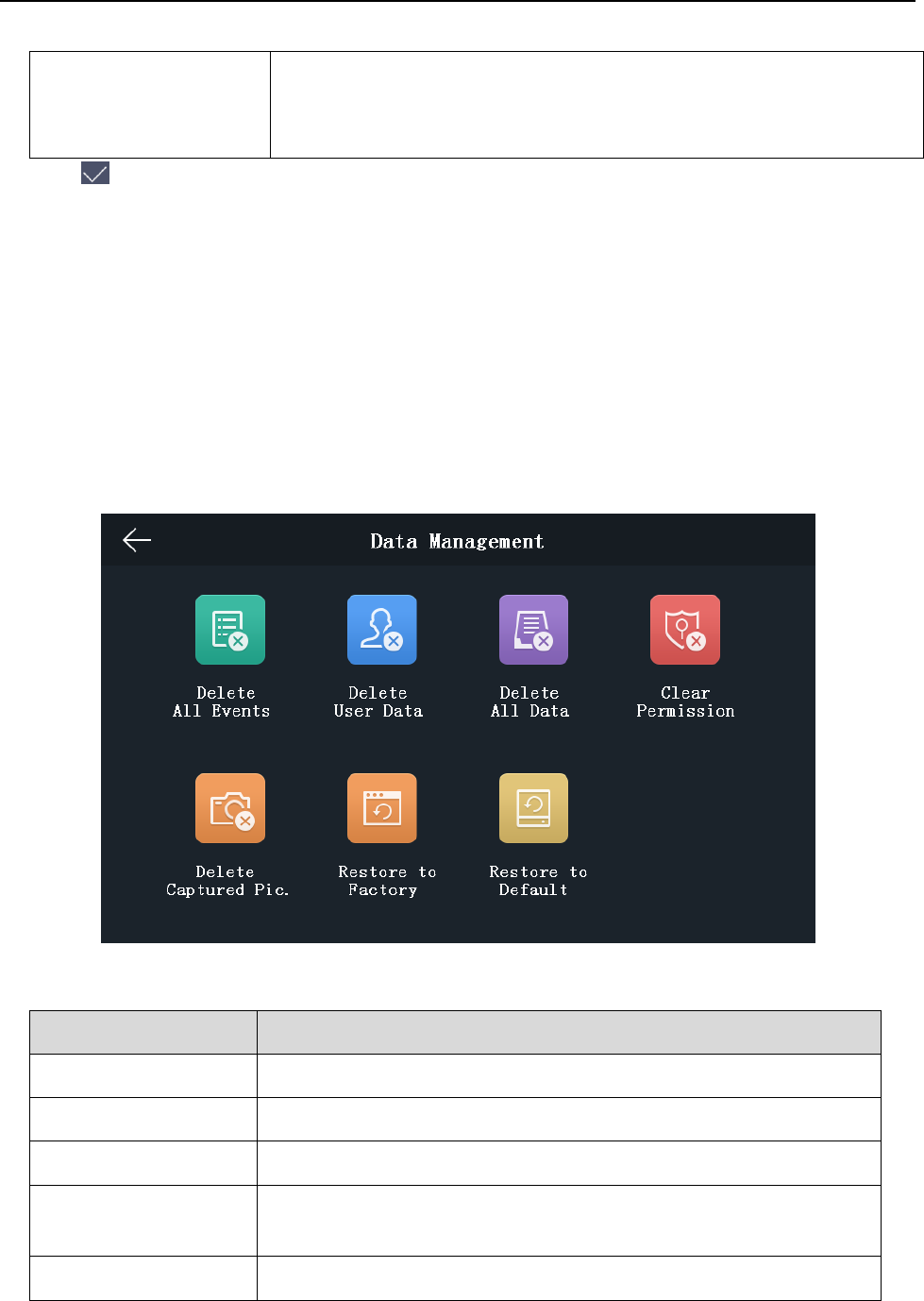
Steps:
1. Tap Data (Data Management) to enter the Data Management page.
2. Tap the button on the page to manage data.
The available button descriptions are as follows:
Parameter
Description
Delete All Events:
Delete all events stored in the device.
Delete User Data:
Delete all user data in the device.
Delete All Data:
Delete all user data and events stored in the device.
Clear Permission:
Clear the administrator’s permission but the administrator and
the related logs will not be deleted.
Delete Captured Pic.:
Delete the device captured pictured.
Face Recognition Terminal User Manual
34
Restore to Factory:
Restore the system to the factory settings. The device will reboot
after the setting.
Restore to Default: s
Restore the system to the default settings. The system will save
the communication settings and the remote user settings. Other
parameters will be restored to default.
3. Tap Yes on the pop-up dialog to complete the settings.
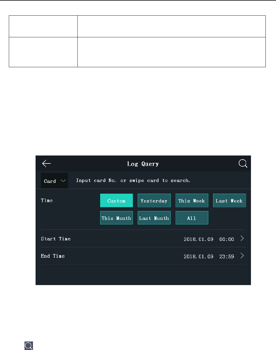
5.6.2 Managing Log Query
Purpose:
You can search the authentication logs within a period of time by inputting employee ID, card No.,
or user name.
Steps:
1. On the Home page, tap Log (Log) to enter the Log page.
2. Tap Card on the left of the page and select a search type from the drop-down list.
3. Tap the input box and input the employee ID, the card No., or the user name for search.
4. Select time.
You can select from Custom, Yesterday, This Week, Last Week, This Month, Last Month, or
All.
If you select Custom, you can customize the start time and the end time for search.
5. Tap to start search.
The result will be displayed in the page.
Face Recognition Terminal User Manual
35
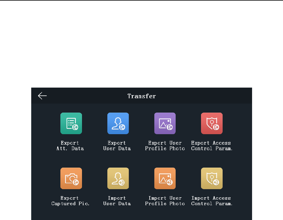
5.6.3 Importing/Exporting Data
Purpose:
On the Transfer page, you can export the attendance data, the user data, the user picture, the
access control parameter, and the captured picture to the USB disk. You can also import the user
data, the user picture, and the access control parameter from the USB disk.
Tap Transfer on the Home page to enter the Transfer page.
Exporting Data
Steps:
1. Plug a USB disk in the device.
2. On the Transfer page, tap Export Att. Data, Export User Data, Export User Profile Photo,
Export Access Control Param., or Export Captured Pic.
3. Tap Yes on the pop-up page and the data will be exported from the device to the USB disk.
Notes:
The supported USB disk format is FAT 32.
The system supports the USB disk with the storage of 1G to 32G. Make sure the free space of
the USB disk is more than 512M.
Importing Data
Steps:
1. Plug a USB disk in the device.
2. On the Transfer page, tap Import User Data, Import User Profile Photo, or Import Access
Control Param.
3. Tap Yes on the pop-up window and the data will be imported from the USB disk to the device.
Notes:
You should import the user data before importing the profile photo.
Face Recognition Terminal User Manual
36
The supported USB disk format is FAT 32.
The imported picture should be saved in the root directory (enroll_pic) and the picture file’s
name should be follow the rule below:
Card No._Name_Department_Employee ID_Gender.jpg
The employee ID should between 1 and 99999999, should not be duplicated, and should not
start with 0.
Requirements of face picture: It should be taken in full-face view, directly facing the camera.
Do not wear a hat or head covering when taking the face picture. The format should be JPEG
or JPG. The resolution should be more than 640 × 480 pixel and less than 2160 × 3840 pixel.
The picture size should between 40 KB and 200 KB.
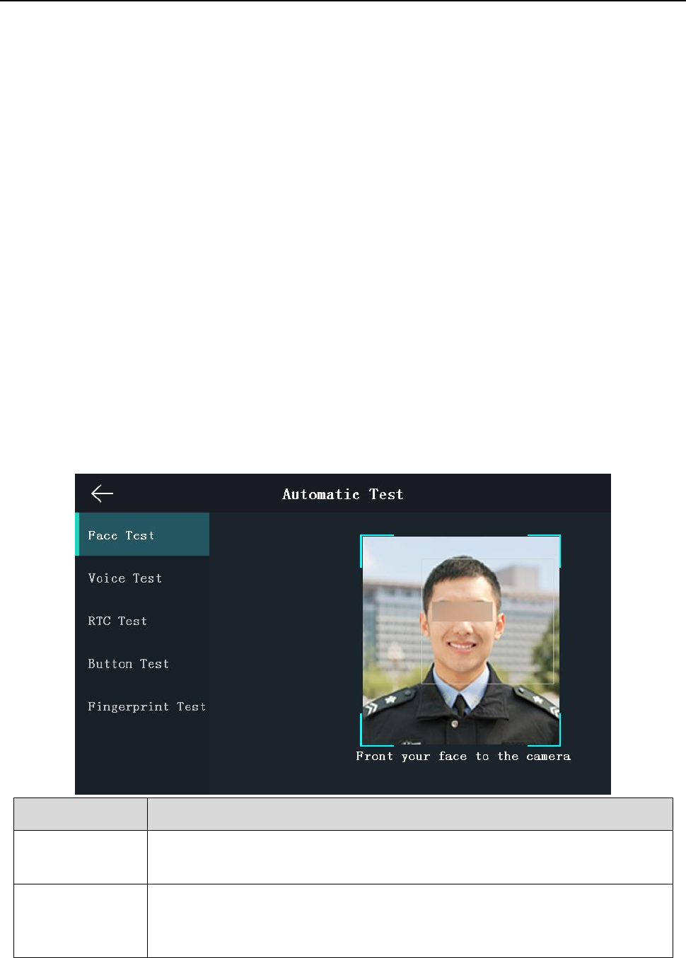
5.6.4 Testing
Purpose:
You can test the capability of the device’s face detection function, voice prompt function,
fingerprint authentication function, time, and button.
Note: The device with the model of DS-K1T605E/M/S or DS-K1T605M-B does not support the
fingerprint function.
Tap Test on the Home page to enter the Automatic Test page.
Parameters
Description
Face Test:
Position your face looking at the camera and the device will test the face
detection function.
Voice Test:
If the voice prompt function is working properly, you will hear the voice
prompt “Authenticated” from the device. And there will also be a prompt
on the page.
Face Recognition Terminal User Manual
37
RTC Test:
If the device RTC is working properly, the page will display the device
current time.
Button Test:
Press the doorbell button. If the button is working properly, the doorbell
icon on the page will turn to blue.
Fingerprint Test:
Tap Start on the page, and put your finger on the fingerprint module. If
the function is working properly, the page will display the fingerprint
quality.
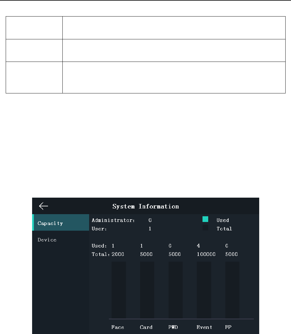
5.6.5 Viewing System Information
Viewing Capacity
Purpose:
You can view the added user’s number, the face picture’s number, the card’s number, the
password’s number, and the fingerprint’s number.
Note: The device with the model of DS-K1T605E/M/S and DS-K1T605M-B do not support the
fingerprint function.
Tap Info. (System Information) on the Home page to enter the System Information page.
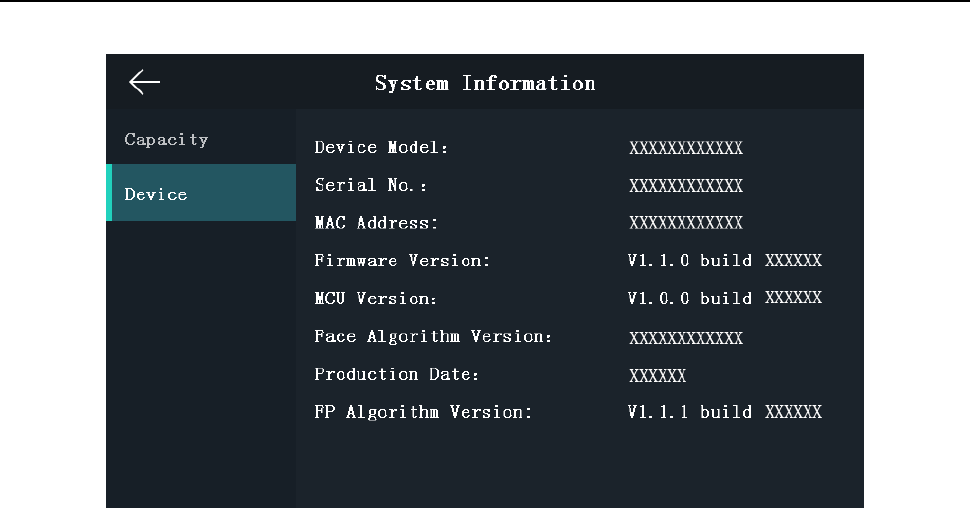
Viewing Device Information
Purpose:
You can view the device model, the serial No., the MAC address, the firmware version, MCU
version, the face algorithm version, the production date, and the fingerprint algorithm version.
Note: The device information page may vary according to different device models.
Face Recognition Terminal User Manual
38
5.7 Authenticating Identity
Purpose:
You can authenticate identity via 1:1 matching or 1:N matching. We suggest that if it is difficult to
recognize the face, you can use the 1:1 face matching mode. If the light or the other elements that
affect the face recognition, you can use fingerprint authentication or other authentication modes.
Note: If you require a higher security level, do not use single authentication mode.
1:N Matching:
Compare the captured face picture or the collected fingerprint picture with all
face pictures or all fingerprint pictures stored in the device
1: 1 Matching:
Compare the captured face picture or the collected fingerprint picture with the
face picture or the fingerprint picture or the password that related to the input
employee ID.
5.7.1 Authenticating via 1:1 Matching
Steps:
1. On the Initial page, tap 1:1 at the lower right corner of the page to enter the 1:1 matching
page.

Face Recognition Terminal User Manual
39
2. Input the employee ID.
3. Tap , , or to authenticate via face picture, fingerprint, or password.
Note: Tap to switch to the password inputting page. You can input the super password or
duress code for authentication.
5.7.2 Authenticating via Other Types
Steps:
1. According to the configured authentication mode, authenticate by comparing face pictures,
fingerprints or by swiping card.
Face Picture
Authentication:
Stand in front of the device. Position your face looking at the camera and
the device will enter the face picture authentication mode.
Note: For detailed information about authenticating face picture, see
Appendix B Tips When Collecting/Comparing Face Picture.
Fingerprint Picture
Authentication:
Scan your fingerprint on the fingerprint module of the device. For
detailed information about scanning fingerprint, see Appendix A Tips for
Scanning Fingerprint.
Authentication by
Swiping Card
Swipe card above the card swiping area.
2. If the user has no other authentication modes, the authentication is completed.
If the user has other authentication modes after the first authentication, follow the instructions
to continue authenticating until the authentication is completed.
Face Recognition Terminal User Manual
40
Chapter 6 Client Operation
You can set and operate the access control devices via the client software. This chapter will
introduce the access control device related operations in the client software. For integrated
operations, refer to User Manual of iVMS-4200 Client Software.
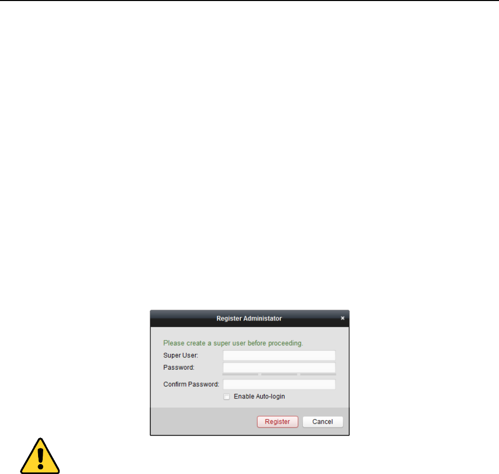
6.1 User Registration and Login
For the first time to use iVMS-4200 client software, you need to register a super user for login.
Steps:
1. Input the super user name and password. The software will judge password strength
automatically, and we highly recommend you to use a strong password to ensure your data
security.
2. Confirm the password.
3. Optionally, check the checkbox Enable Auto-login to log into the software automatically.
4. Click Register. Then, you can log into the software as the super user.
A user name cannot contain any of the following characters: / \ : * ? “ < > |. And the length
of the password cannot be less than 6 characters.
For your privacy, we strongly recommend changing the password to something of your own
choosing (using a minimum of 8 characters, including upper case letters, lower case letters,
numbers, and special characters) in order to increase the security of your product.
Proper configuration of all passwords and other security settings is the responsibility of the
installer and/or end-user.
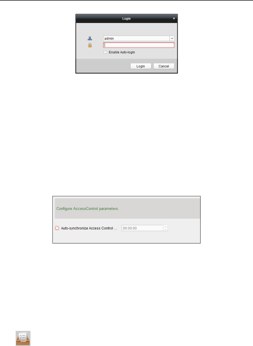
When opening iVMS-4200 after registration, you can log into the client software with the
registered user name and password.
Steps:
1. Input the user name and password you registered.
2. Optionally, check the checkbox Enable Auto-login to log into the software automatically.
3. Click Login.
Face Recognition Terminal User Manual
41
After running the client software, you can open the wizards (including video wizard, video wall
wizard, security control panel wizard, access control and video intercom wizard, and attendance
wizard), to guide you to add the device and do other settings and operations. For detailed
configuration about the wizards, please refer to the Quick Start Guide of iVMS-4200.
6.2 System Configuration
Purpose:
You can synchronize the missed access control events to the client.
Steps:
1. Click Tool – System Configuration.
2. In the System Configuration window, check the Auto-synchronize Access Control Event
checkbox.
3. Set the synchronization time.
The client will auto-synchronize the missed access control event to the client at the set time.
6.3 Access Control Management
Purpose:
The Access Control module is applicable to access control devices and video intercom. It provides
multiple functionalities, including person and card management, permission configuration, access
control status management, video intercom, and other advanced functions.
You can also set the event configuration for access control and display access control points and
zones on E-map.
Note: For the user with access control module permissions, the user can enter the Access Control
module and configure the access control settings.
Click in the control panel, and check Access Control to add the Access Control module to
the control panel.
Face Recognition Terminal User Manual
42
Click to enter the Access Control module.
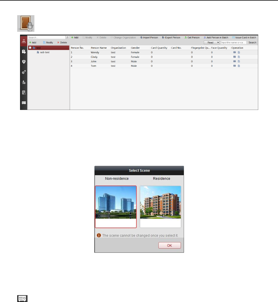
Before you start:
For the first time opening the Access Control module, the following dialog will pop up and you are
required to select the scene according to the actual needs.
Non-residence: You can set the attendance rule when adding person, while set the access control
parameters.
Residence: You cannot set the attendance rule when adding person.
Note: Once the scene is configured, you cannot change it later.
6.3.1 Adding Access Control Device
Click in the Access Control module to enter the following interface.
Face Recognition Terminal User Manual
43
Note: After adding the device, you should check the device arming status in Tool – Device Arming
Control. If the device is not armed, you should arm it, or you will not receive the real-time events
via the client software. For details about device arming control, refer 6.12 Arming Control.
Creating Password
Purpose:
For some devices, you are required to create the password to activate them before they can be
added to the software and work properly.
Note: This function should be supported by the device.
Steps:
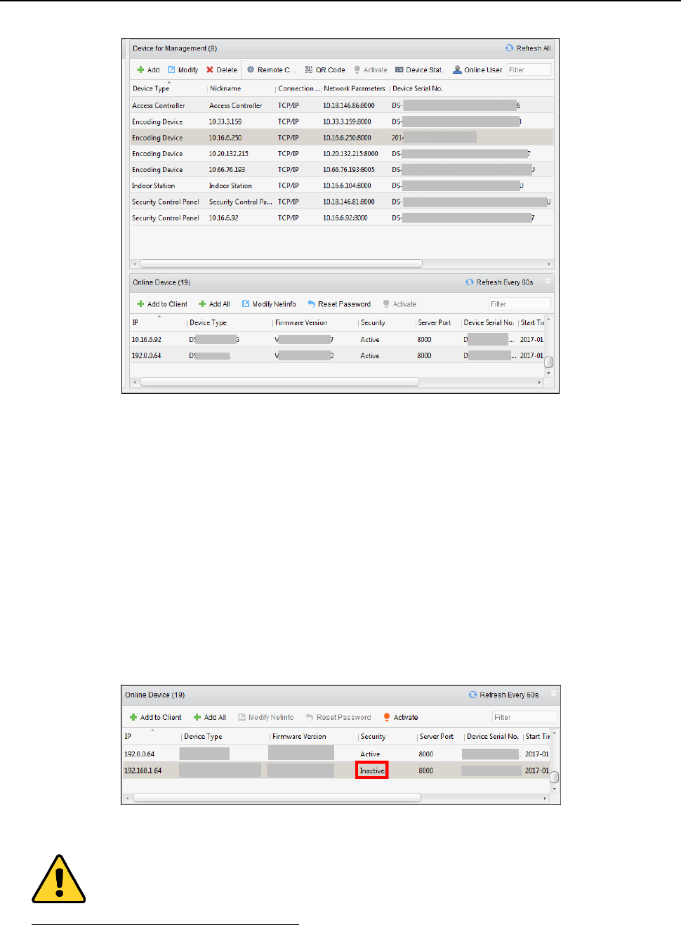
1. Enter the Device Management page.
2. On the Device for Management or Online Device area, check the device status (shown on
Security column) and select an inactive device.
3. Click the Activate button to pop up the Activation interface.
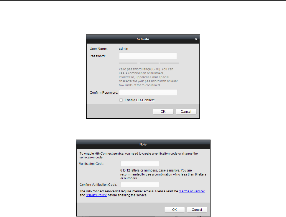
4. Create a password in the password field, and confirm the password.
STRONG PASSWORD RECOMMENDED– We highly recommend you create a strong password
of your own choosing (using a minimum of 8 characters, including upper case letters, lower
case letters, numbers, and special characters) in order to increase the security of your product.
Face Recognition Terminal User Manual
44
And we recommend you reset your password regularly, especially in the high security system,
resetting the password monthly or weekly can better protect your product.
5. (Optional) Enable Hik-Connect service when activating the device if the device supports.
1) Check Enable Hik-Connect checkbox to pop up the Note dialog.
2) Create a verification code.
3) Confirm the verification code.
4) Click Terms of Service and Privacy Policy to read the requirements.
5) Click OK to enable the Hik-Connect service.
6. Click OK to activate the device.
A “The device is activated.” window pops up when the password is set successfully.
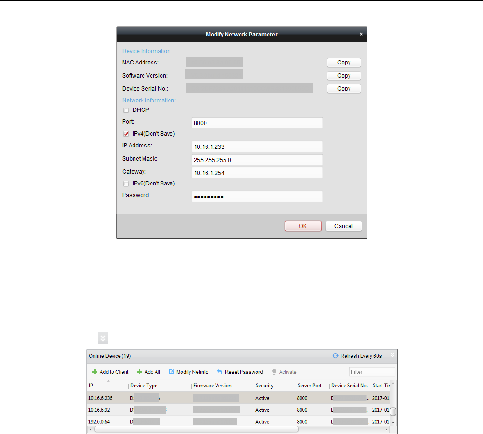
7. Click Modify Netinfo to pop up the Modify Network Parameter interface.
Note: This function is only available on the Online Device area. You can change the device IP
address to the same subnet with your computer if you need to add the device to the software.
8. Change the device IP address to the same subnet with your computer by either modifying the
IP address manually or checking the checkbox of DHCP.
9. Input the password set in step 4 and click OK to complete the network settings.
Face Recognition Terminal User Manual
45
Adding Online Device
Purpose:
The active online devices in the same local subnet with the client software will be displayed on the
Online Device area. You can click the Refresh Every 60s button to refresh the information of the
online devices.
Note: You can click to hide the Online Device area.
Steps:
1. Select the devices to be added from the list.
Note: For the inactive device, you need to create the password for it before you can add the
device properly. For detailed steps, please refer to Chapter 5
Face Recognition Terminal User Manual
46
.
2. Click Add to Client to open the device adding dialog box.
3. Input the required information.
Nickname: Edit a name for the device as you want.
Address: Input the device’s IP address. The IP address of the device is obtained automatically in
this adding mode.
Port: Input the device port No. The default value is 8000.
User Name: Input the device user name. By default, the user name is admin.
Password: Input the device password.
STRONG PASSWORD RECOMMENDED– We highly recommend you create a strong password
of your own choosing (using a minimum of 8 characters, including upper case letters, lower
case letters, numbers, and special characters) in order to increase the security of your product.
And we recommend you reset your password regularly, especially in the high security system,
resetting the password monthly or weekly can better protect your product.
4. Optionally, check the Export to Group checkbox to create a group by the device name.
You can import all the channels of the device to the corresponding group by default.
Note: iVMS-4200 also provides a method to add the offline devices.
1) Check the Add Offline Device checkbox.
2) Input the required information, including the device channel number and alarm input
number.
3) Click Add.
When the offline device comes online, the software will connect it automatically.
5. Click Add to add the device.
Adding Multiple Online Device
If you want to add multiple online devices to the client software, click and hold Ctrl key to
Face Recognition Terminal User Manual
47
select multiple devices, and click Add to Client to open the device adding dialog box. In the
pop-up message box, enter the user name and password for the devices to be added.
Adding All Online Devices
If you want to add all the online devices to the client software, click Add All and click OK in the
pop-up message box. Then enter the user name and password for the devices to be added.
Adding Devices by IP or Domain Name
Steps:
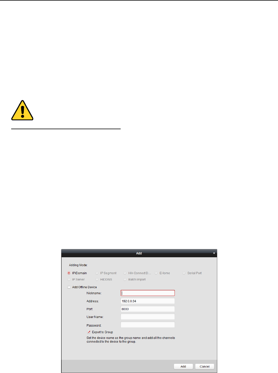
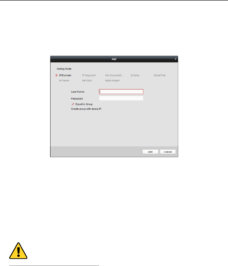
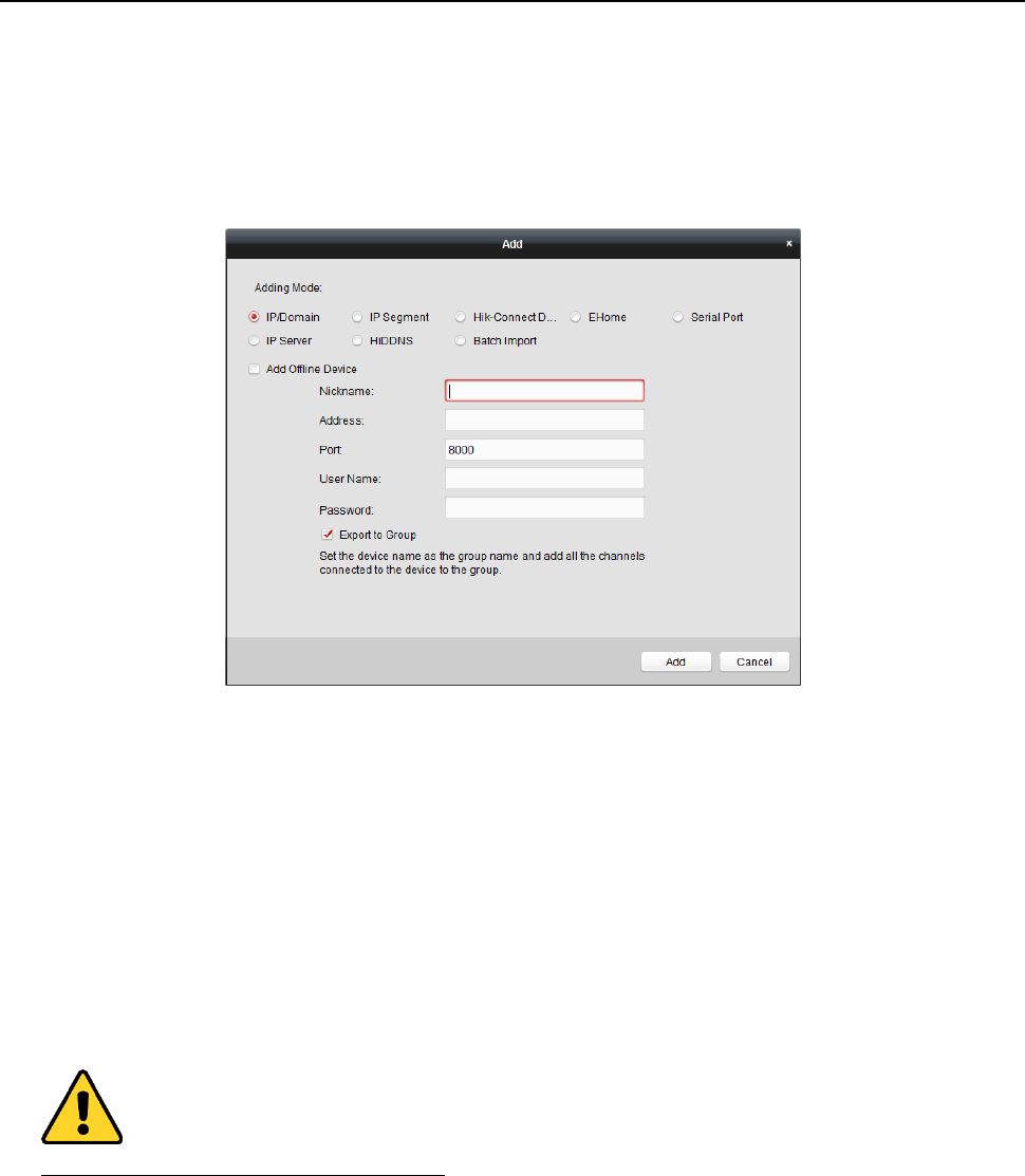
1. Click Add to open the device adding dialog box.
2. Select IP/Domain as the adding mode.
3. Input the required information.
Nickname: Edit a name for the device as you want.
Address: Input the device’s IP address or domain name.
Port: Input the device port No.. The default value is 8000.
User Name: Input the device user name. By default, the user name is admin.
Password: Input the device password.
STRONG PASSWORD RECOMMENDED– We highly recommend you create a strong password
of your own choosing (using a minimum of 8 characters, including upper case letters, lower
case letters, numbers, and special characters) in order to increase the security of your product.
And we recommend you reset your password regularly, especially in the high security system,
resetting the password monthly or weekly can better protect your product.
4. Optionally, check the Export to Group checkbox to create a group by the device name.
You can import all the channels of the device to the corresponding group by default.
Note: iVMS-4200 also provides a method to add the offline devices.
1) Check the Add Offline Device checkbox.
Face Recognition Terminal User Manual
48
2) Input the required information, including the device channel number and alarm input
number.
3) Click Add.
When the offline device comes online, the software will connect it automatically.
5. Click Add to add the device.
Adding Devices by IP Segment
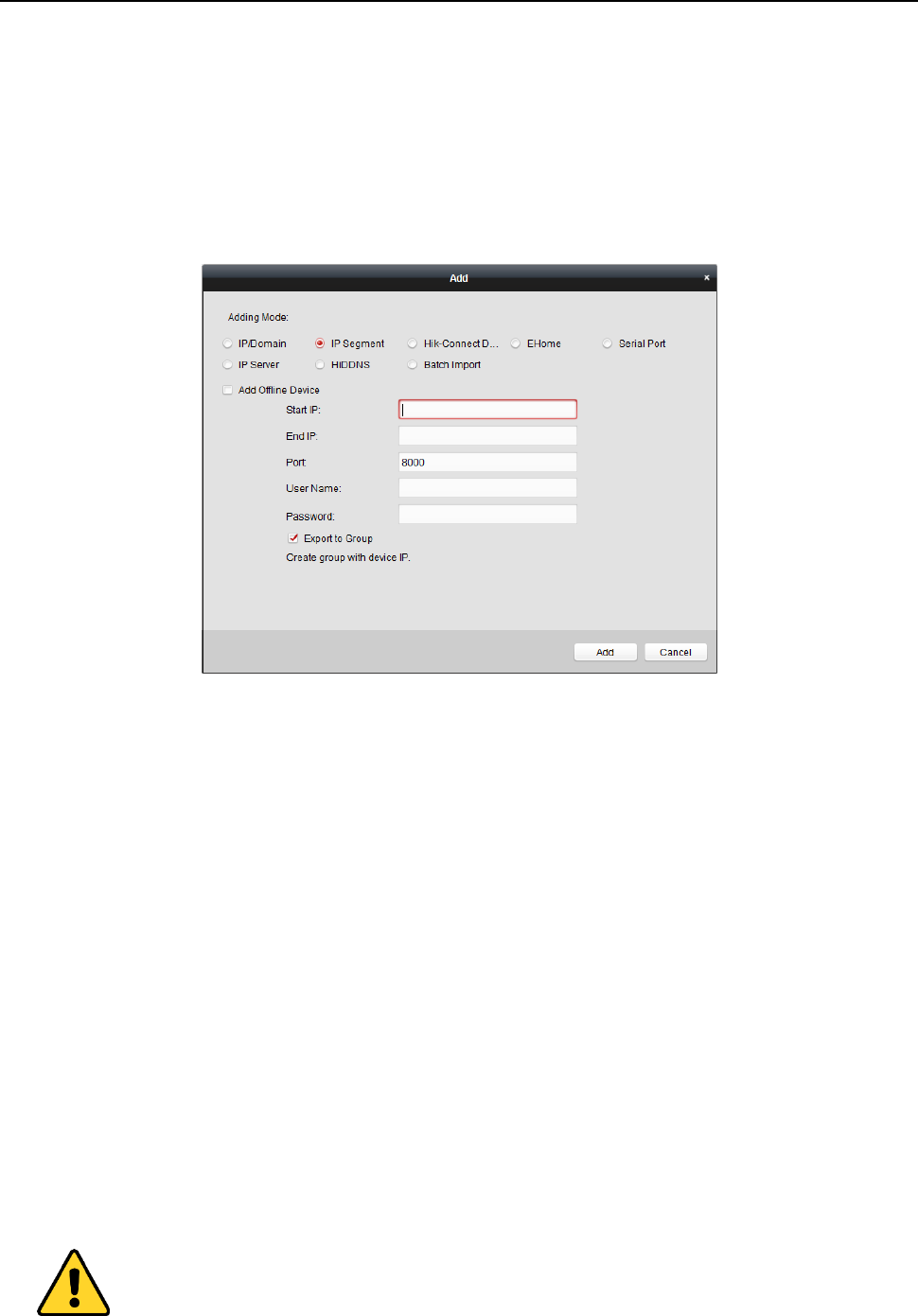
Steps:
1. Click Add to open the device adding dialog box.
2. Select IP Segment as the adding mode.
3. Input the required information.
Start IP: Input a start IP address.
End IP: Input an end IP address in the same network segment with the start IP.
Port: Input the device port No.. The default value is 8000.
User Name: Input the device user name. By default, the user name is admin.
Password: Input the device password.
STRONG PASSWORD RECOMMENDED– We highly recommend you create a strong password
of your own choosing (using a minimum of 8 characters, including upper case letters, lower
case letters, numbers, and special characters) in order to increase the security of your product.
And we recommend you reset your password regularly, especially in the high security system,
resetting the password monthly or weekly can better protect your product.
4. Optionally, check the Export to Group checkbox to create a group by the device name.
You can import all the channels of the device to the corresponding group by default.
Note: iVMS-4200 also provides a method to add the offline devices.
1) Check the Add Offline Device checkbox.
Face Recognition Terminal User Manual
49
2) Input the required information, including the device channel number and alarm input
number.
3) Click Add.
When the offline device comes online, the software will connect it automatically.
5. Click Add.
You can add the device which the IP address is between the start IP and end IP to the device
list.
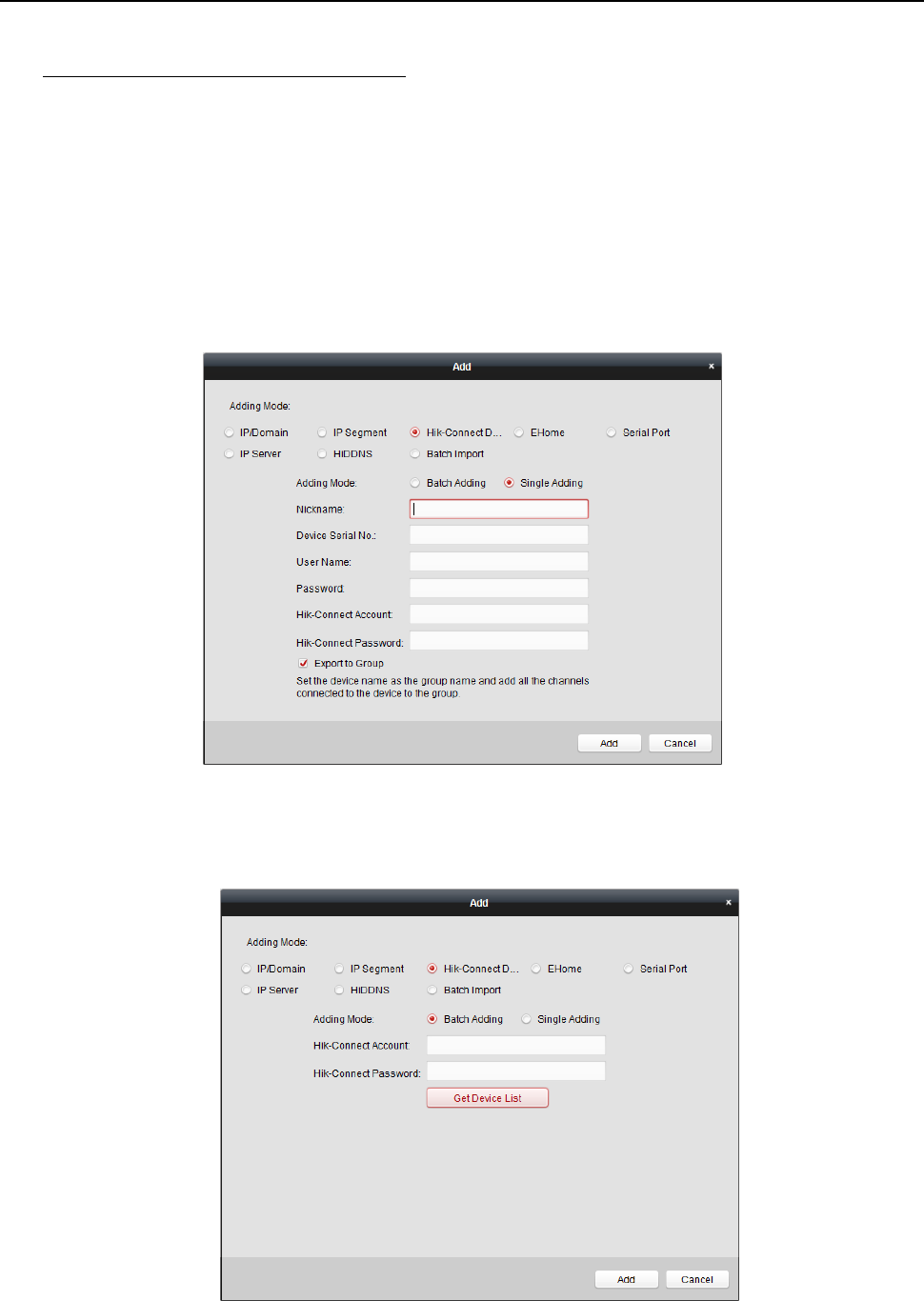
Adding Devices by Hik-Connect Domain
Purpose:
You can add the devices connected via Hik-Connect by inputting the Hik-Connect account and
password.
Before you start: Add the devices to Hik-Connect account via iVMS-4200, iVMS-4500 Mobile Client,
or Hik-Connect first. For details about adding the devices to Hik-Connect account via iVMS-4200,
refer to the User Manual of iVMS-4200 Client Software.
Add Single Device
Steps:
1. Click Add to open the device adding dialog.
2. Select Hik-Connect Domain as the adding mode.
3. Select Single Adding.
4. Input the required information.
Nickname: Edit a name for the device as you want.
Device Serial No.: Input the device serial No.
User Name: Input the device user name. By default, the user name is admin.
Password: Input the device password.
Face Recognition Terminal User Manual
50
STRONG PASSWORD RECOMMENDED– We highly recommend you create a strong password
of your own choosing (using a minimum of 8 characters, including upper case letters, lower
case letters, numbers, and special characters) in order to increase the security of your product.
And we recommend you reset your password regularly, especially in the high security system,
resetting the password monthly or weekly can better protect your product.
Hik-Connect Account: Input the Hik-Connect account.
Hik-Connect Password: Input the Hik-Connect password.
5. Optionally, check the Export to Group checkbox to create a group by the device name.
You can import all the channels of the device to the corresponding group by default.
6. Click Add to add the device.
Add Devices in Batch
Steps:
1. Click Add to open the device adding dialog.
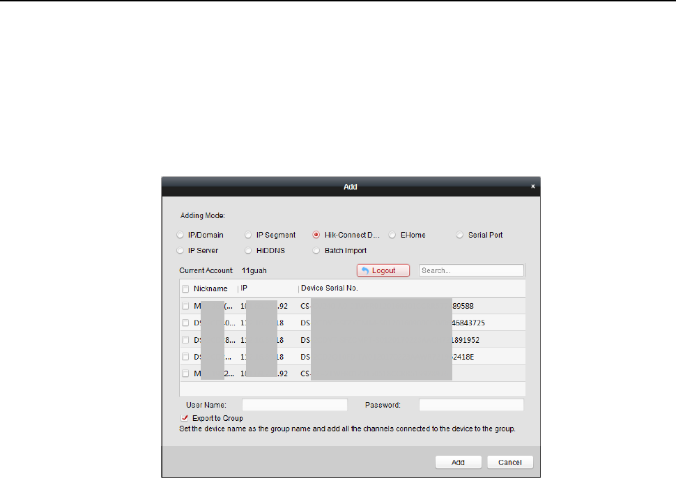
Face Recognition Terminal User Manual
51
2. Select Hik-Connect Domain as the adding mode.
3. Select Batch Adding.
4. Input the required information.
Hik-Connect Account: Input the Hik-Connect account.
Hik-Connect Password: Input the Hik-Connect password.
5. Click Get Device List to show the devices added to Hik-Connect account.
6. Check the checkbox(es) to select the device as desired.
7. Input the user name and password for the devices to be added.
8. Optionally, check the Export to Group checkbox to create a group by the device name.
You can import all the channels of the device to the corresponding group by default.
9. Click Add to add the devices.
Adding Devices by EHome Account
Purpose:
You can add access control device connected via EHome protocol by inputting the EHome account.
Before you start: Set the network center parameter first. For details, refer to Chapter 6.3.4
Network Settings.
Steps:
1. Click Add to open the device adding dialog box.
2. Select EHome as the adding mode.
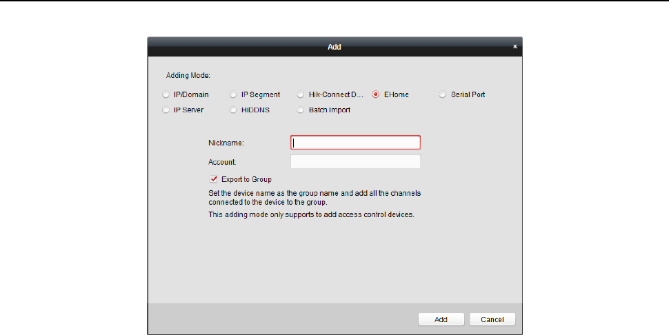
Face Recognition Terminal User Manual
52
3. Input the required information.
Nickname: Edit a name for the device as you want.
Account: Input the account name registered on EHome protocol.
4. Optionally, check the Export to Group checkbox to create a group by the device name.
You can import all the channels of the device to the corresponding group by default.
Note: iVMS-4200 also provides a method to add the offline devices.
1) Check the Add Offline Device checkbox.
2) Input the required information, including the device channel number and alarm input
number.
3) Click Add.
When the offline device comes online, the software will connect it automatically.
5. Click Add to add the device.
Adding Devices by Serial Port
Purpose:
You can add access control device connected via serial port.
Steps:
1. Click Add to open the device adding dialog box.
2. Select Serial Port as the adding mode.
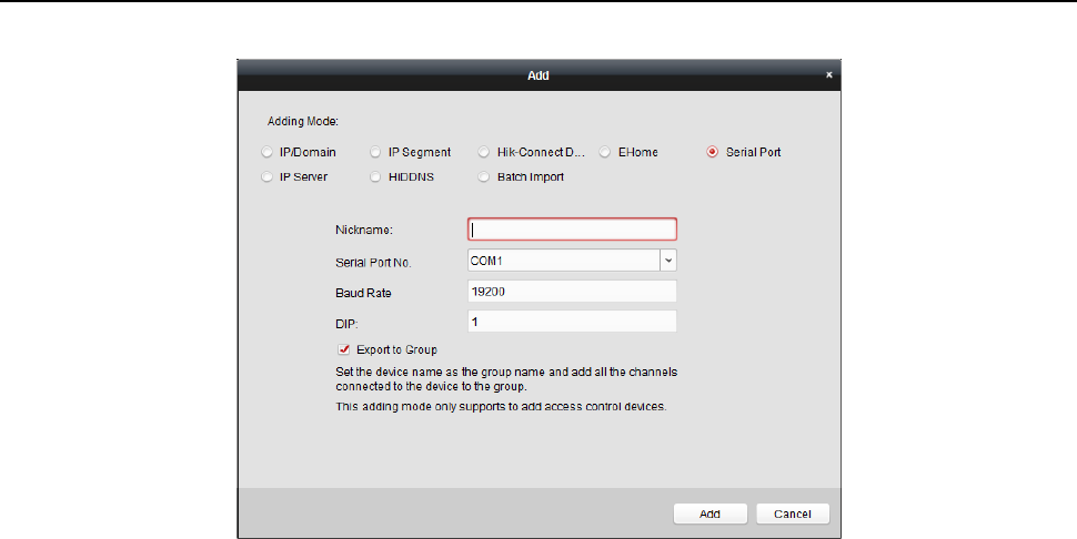
Face Recognition Terminal User Manual
53
3. Input the required information.
Nickname: Edit a name for the device as you want.
Serial Port No.: Select the device’s connected serial port No.
Baud Rate: Input the baud rate of the access control device.
DIP: Input the DIP address of the device.
4. Optionally, check the Export to Group checkbox to create a group by the device name.
You can import all the channels of the device to the corresponding group by default.
Note: iVMS-4200 also provides a method to add the offline devices.
1) Check the Add Offline Device checkbox.
2) Input the required information, including the device channel number and alarm input
number.
3) Click Add.
When the offline device comes online, the software will connect it automatically.
5. Click Add to add the device.
Adding Devices by IP Server
Steps:
1. Click Add to open the device adding dialog box.
2. Select IP Server as the adding mode.
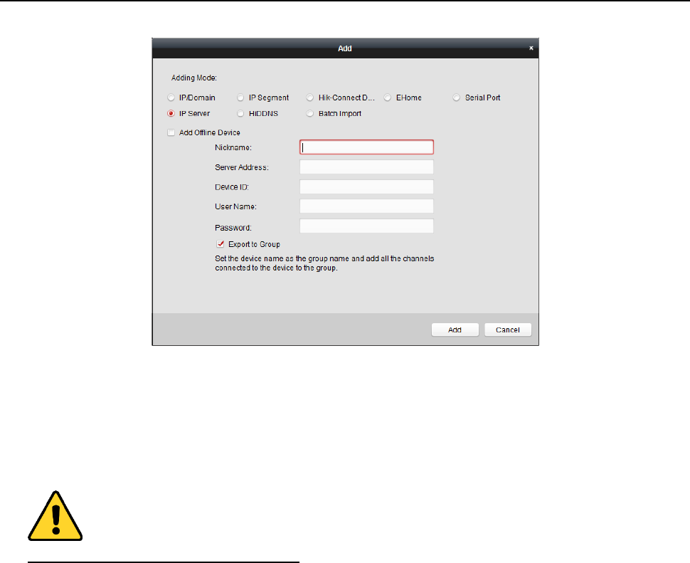
Face Recognition Terminal User Manual
54
3. Input the required information.
Nickname: Edit a name for the device as you want.
Server Address: Input the IP address of the PC that installs the IP Server.
Device ID: Input the device ID registered on the IP Server.
User Name: Input the device user name. By default, the user name is admin.
Password: Input the device password.
STRONG PASSWORD RECOMMENDED– We highly recommend you create a strong password
of your own choosing (using a minimum of 8 characters, including upper case letters, lower
case letters, numbers, and special characters) in order to increase the security of your product.
And we recommend you reset your password regularly, especially in the high security system,
resetting the password monthly or weekly can better protect your product.
4. Optionally, check the Export to Group checkbox to create a group by the device name.
You can import all the channels of the device to the corresponding group by default.
Note: iVMS-4200 also provides a method to add the offline devices.
1) Check the Add Offline Device checkbox.
2) Input the required information, including the device channel number and alarm input
number.
3) Click Add.
When the offline device comes online, the software will connect it automatically.
5. Click Add to add the device.
Adding Devices by HiDDNS
Steps:
1. Click Add to open the device adding dialog box.
2. Select HiDDNS as the adding mode.
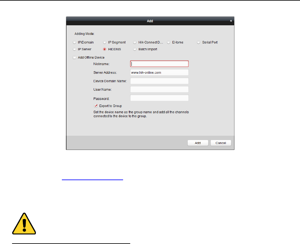
Face Recognition Terminal User Manual
55
3. Input the required information.
Nickname: Edit a name for the device as you want.
Server Address: www.hik-online.com.
Device Domain Name: Input the device domain name registered on HiDDNS server.
User Name: Input the device user name. By default, the user name is admin.
Password: Input the device password.
STRONG PASSWORD RECOMMENDED– We highly recommend you create a strong password
of your own choosing (using a minimum of 8 characters, including upper case letters, lower
case letters, numbers, and special characters) in order to increase the security of your product.
And we recommend you reset your password regularly, especially in the high security system,
resetting the password monthly or weekly can better protect your product.
4. Optionally, check the Export to Group checkbox to create a group by the device name.
You can import all the channels of the device to the corresponding group by default.
Note: iVMS-4200 also provides a method to add the offline devices.
1) Check the Add Offline Device checkbox.
2) Input the required information, including the device channel number and alarm input
number.
3) Click Add.
When the offline device comes online, the software will connect it automatically.
5. Click Add to add the device.
Importing Devices in Batch
Purpose:
The devices can be added to the software in batch by inputting the device information in the
pre-defined CSV file.
Steps:
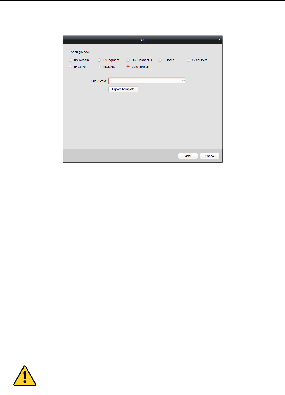
Face Recognition Terminal User Manual
56
1. Click Add to open the device adding dialog box.
2. Select Batch Import as the adding mode.
3. Click Export Template and save the pre-defined template (CSV file) on your PC.
4. Open the exported template file and input the required information of the devices to be added
on the corresponding column.
Nickname: Edit a name for the device as you want.
Adding Mode: You can input 0, 2, 3, 4, 5, or 6 which indicated different adding modes. 0
indicates that the device is added by IP address or domain name; 2 indicates that the
device is added via IP server; 3 indicates that the device is added via HiDDNS; 4 indicates
that the device is added via EHome protocol; 5 indicates that the device is added by serial
port; 6 indicates that the device is added via Hik-Connect Domain.
Address: Edit the address of the device. If you set 0 as the adding mode, you should input
the IP address or domain name of the device; if you set 2 as the adding mode, you should
input the IP address of the PC that installs the IP Server; if you set 3 as the adding mode,
you should input www.hik-online.com.
Port: Input the device port No.. The default value is 8000.
Device Information: If you set 0 as the adding mode, this field is not required; if you set 2
as the adding mode, input the device ID registered on the IP Server; if you set 3 as the
adding mode, input the device domain name registered on HiDDNS server; if you set 4 as
the adding mode, input the EHome account; if you set 6 as the adding mode, input the
device serial No.
User Name: Input the device user name. By default, the user name is admin.
Password: Input the device password.
STRONG PASSWORD RECOMMENDED– We highly recommend you create a strong password
of your own choosing (using a minimum of 8 characters, including upper case letters, lower

Face Recognition Terminal User Manual
57
case letters, numbers, and special characters) in order to increase the security of your product.
And we recommend you reset your password regularly, especially in the high security system,
resetting the password monthly or weekly can better protect your product.
Add Offline Device: You can input 1 to enable adding the offline device, and then the
software will automatically connect it when the offline device comes online. 0 indicates
disabling this function.
Export to Group: You can input 1 to create a group by the device name (nickname). All the
channels of the device will be imported to the corresponding group by default. 0 indicates
disabling this function.
Channel Number: If you set 1 for Add Offline Device, input the channel number of the
device. If you set 0 for Add Offline Device, this field is not required.
Alarm Input Number: If you set 1 for Add Offline Device, input the alarm input number of
the device. If you set 0 for Add Offline Device, this field is not required.
Serial Port No.: If you set 5 as the adding mode, input the serial port No. for the access
control device.
Baud Rate: If you set 5 as the adding mode, input the baud rate of the access control
device.
DIP: If you set 5 as the adding mode, input the DIP address of the access control device.
Hik-Connect Account: If you set 6 as the adding mode, input the Hik-Connect account.
Hik-Connect Password: If you set 6 as the adding mode, input the Hik-Connect password.
5. Click and select the template file.
6. Click Add to import the devices.
The devices will be displayed on the device list for management after added successfully. You can
check the resource usage, HDD status, recording status, and other information of the added
devices on the list.
Click Refresh All to refresh the information of all added devices. You can also input the device
name in the filter field for search.
6.3.2 Viewing Device Status
In the device list, you can select the device and then click Device Status button to view its status.
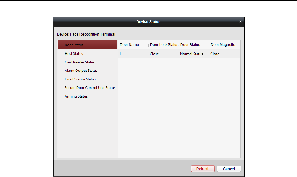
Face Recognition Terminal User Manual
58
Note: The interface may different from the picture displayed above. Refer to the actual interface
when adopting this function.
Door Status: The status of the connected door.
Host Status: The status of the host, including Storage Battery Power Voltage, Device Power
Supply Status, Multi-door Interlocking Status, Anti-passing Back Status, and Host Anti-Tamper
Status.
Card Reader Status: The status of card reader.
Note: If you use the card reader with RS-485 connection, you can view the status of online or
offline. If you use the card reader with Wiegand connection, you can view the status of offline.
Alarm Output Status: The alarm output status of each port.
Event Sensor Status: The event sensor status of each port.
Secure Door Control Unit Status: The online status and tamper status of the Secure Door
Control Unit.
Arming Status: The status of the device.
6.3.3 Editing Basic Information
Purpose:
After adding the access control device, you can edit the device basic information.
Steps:
1. Select the device in the device list.
2. Click Modify to pop up the modifying device information window.
3. Click Basic Information tab to enter the Basic Information interface.
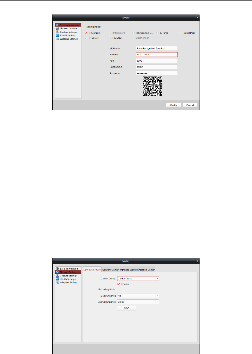
Face Recognition Terminal User Manual
59
4. Edit the device information, including the adding mode, the device name, the device IP address,
port No., user name, and the password.
6.3.4 Network Settings
Purpose:
After adding the access control device, you can set the uploading mode, and set the network
center and wireless communication center.
Select the device in the device list, and click Modify to pop up the modifying device information
window.
Click Network Settings tab to enter the network settings interface.
Uploading Mode Settings
Purpose
:
You can set the center group for uploading the log via the EHome protocol.
Steps:
1. Click the Uploading Mode tab.
2. Select the center group in the dropdown list.
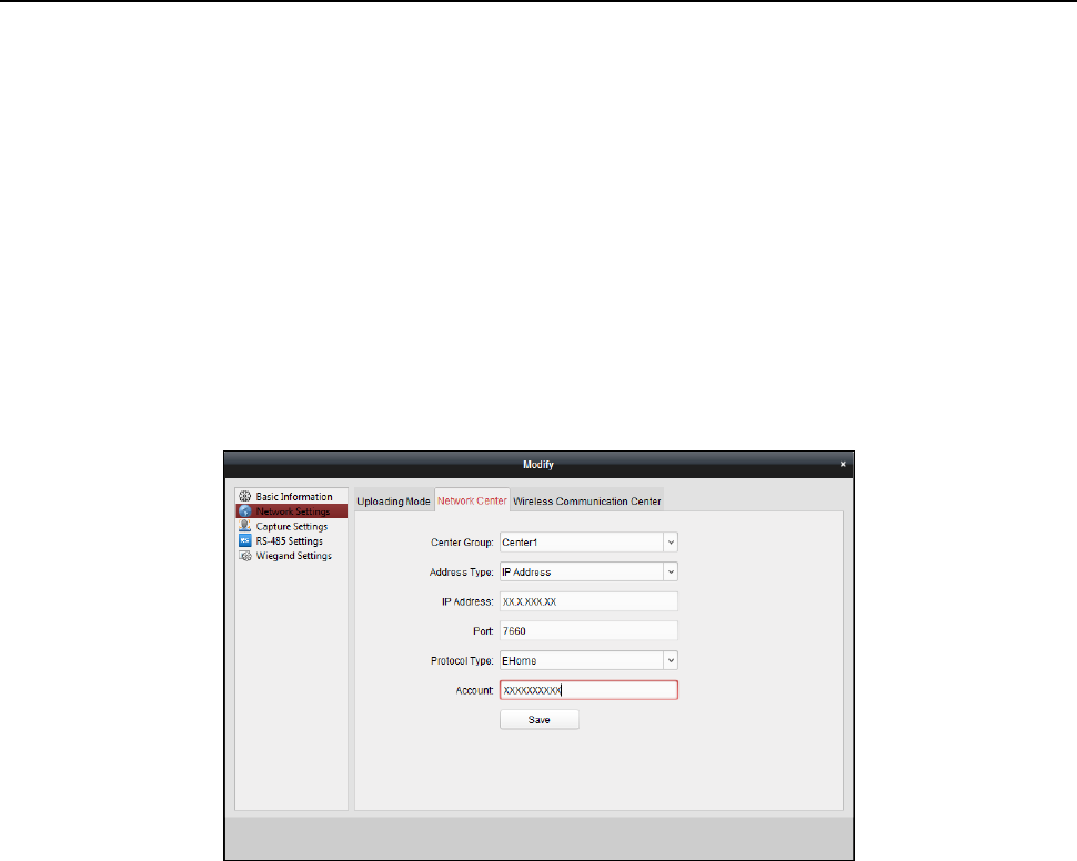
Face Recognition Terminal User Manual
60
3. Check the Enable checkbox to enable the selected center group.
4. Select the uploading mode in the dropdown list. You can enable N1/G1 for the main channel
and the backup channel, or select Close to disable the main channel or the backup channel.
Note: The main channel and the backup channel cannot enable N1 or G1 at the same time.
5. Click Save button to save parameters.
Network Center Settings
You can set the account for EHome protocol in Network Settings page. Then you can add devices
via EHome protocol.
Steps:
1. Click the Network Center tab.
2. Select the center group in the dropdown list.
3. Select the Address Type as IP Address or Domain Name.
4. Input IP address or domain name according to the address type.
5. Input the port No. for the protocol. By default, the port No. is 7660.
6. Select the protocol type as EHome.
7. Set an account name for the network center.
Note: The account should contain 1 to 32 characters and only letters and numbers are allowed.
8. Click Save button to save parameters.
Notes:
The port No. of the wireless network and wired network should be consistent with the port No.
of EHome.
You can set the domain name in Enable NTP area Editing Time section in Remote Configuration.
For details, refer to Time in 6.3.8 Remote Configuration.
Wireless Communication Center Settings
Steps:
1. Click the Wireless Communication Center tab.
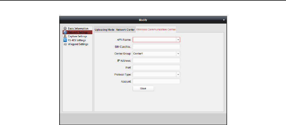
Face Recognition Terminal User Manual
61
2. Select the APN name as CMNET or UNINET.
3. Input the SIM Card No.
4. Select the center group in the dropdown list.
5. Input the IP address and port No.
6. Select the protocol type as EHome. By default, the port No. for EHome is 7660.
7. Set an account name for the network center. A consistent account should be used in one
platform.
8. Click Save button to save parameters.
Note: The port No. of the wireless network and wired network should be consistent with the port
No. of EHome.
6.3.5 Capture Settings
You can set the parameters of capture linkage and manual capture.
Select the device in the device list, and click Modify to pop up the modifying device information
window.
Click Capture Settings tab to enter the capture settings interface.
Notes:
The Capture Settings should be supported by the device.
Before setting the capture setting, you should configure the storage server for picture storage.
Linked Capture
Steps:
1. Select the Linked Capture tab.
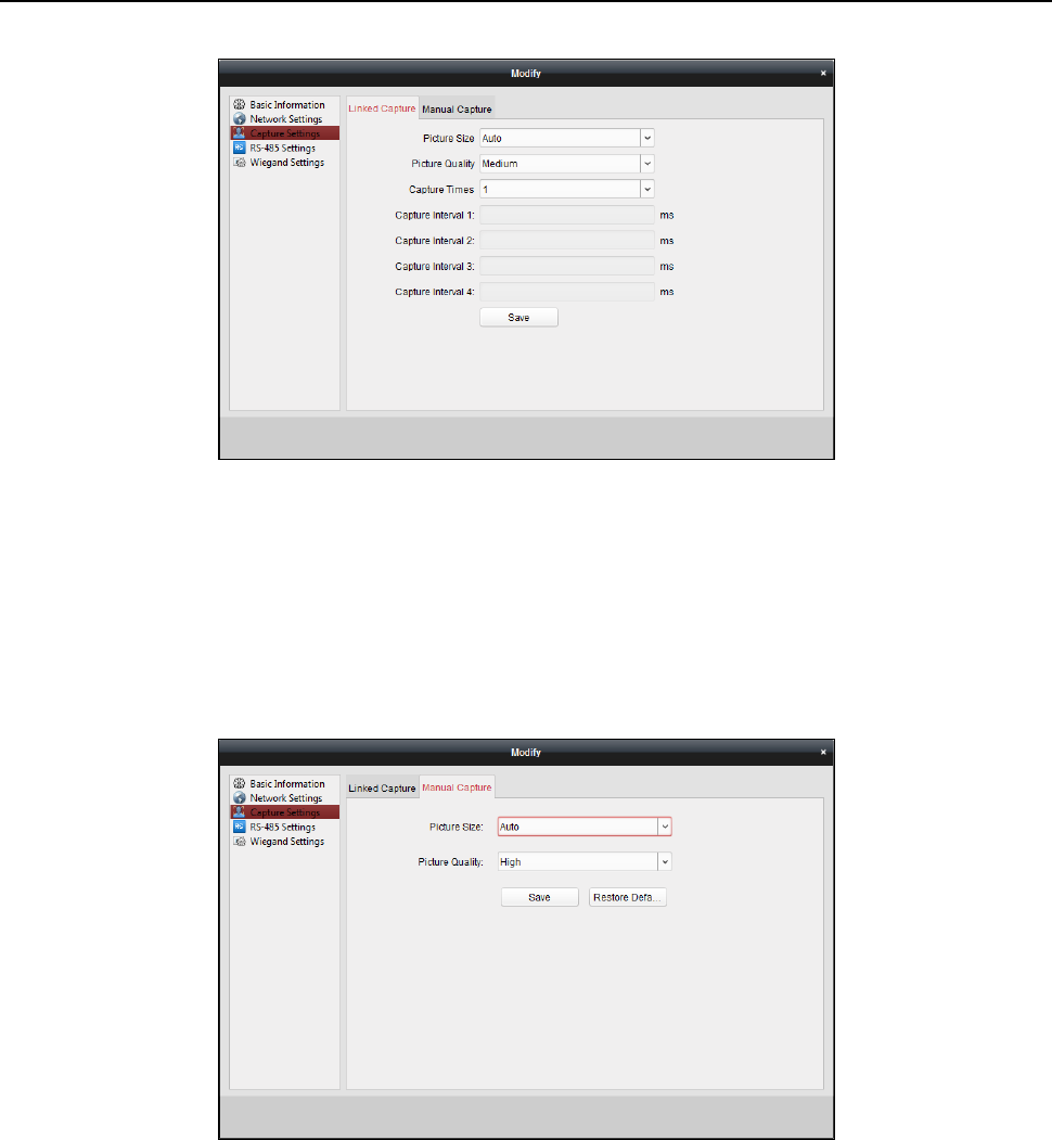
Face Recognition Terminal User Manual
62
2. Set the picture size and quality.
3. Set the linked capture times once triggered.
4. Set the capture interval according to the capture times.
5. Click Save to save the settings.
Manual Capture
Steps:
1. Select the Manual Capture tab.
2. Select the resolution of the captured pictures from the dropdown list.
3. Select the picture quality as High, Medium, or Low.
4. Click Save to save the settings.
5. You can click Restore Default Value to restore the parameters to default settings.
6.3.6 RS-485 Settings
Purpose:
You can set the RS-485 parameters including the serial port, the baud rate, the data bit, the stop
bit, the parity type, the communication mode, the working mode, and the connection mode.
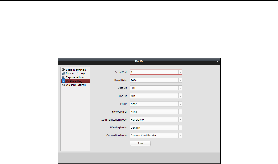
Face Recognition Terminal User Manual
63
Note: The RS-485 Settings should be supported by the device.
Steps:
1. Select the device in the device list, and click Modify to pop up the modifying device
information window.
2. Click RS-485 Settings tab to enter the RS-485 settings interface.
2. Select the serial No. of the port from the dropdown list to set the RS-485 parameters.
3. Set the baud rate, data bit, the stop bit, parity, flow control, communication mode, working
mode, and the connection mode in the dropdown list.
4. Click Save to save the settings and the configured parameters will be applied to the device
automatically.
Note: After changing the working mode, the device will be rebooted. A prompt will be popped up
after changing the working mode.
6.3.7 Wiegand Settings
Purpose:
You can set the Wiegand channel and the communication mode.
Note: The Wiegand Settings should be supported by the device.
Steps:
1. Select the device in the device list, and click Modify to pop up the modifying device
information window.
2. Click the Wiegand Settings tab to enter the Wiegand Settings interface.
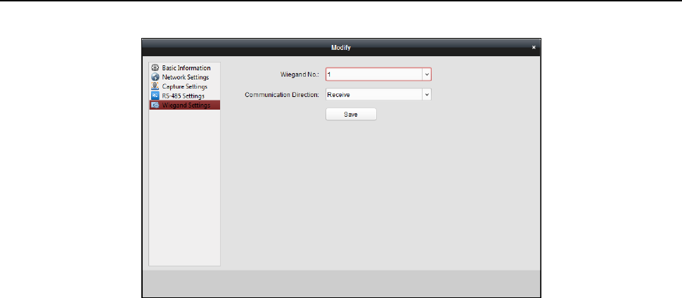
Face Recognition Terminal User Manual
64
3. Select the Wiegand channel No. and the communication mode in the dropdown list.
If you set the Communication Direction as Send, you are required to set the Wiegand Mode as
Wiegand 26 or Wiegand 34.
4. Click Save to save the settings and the configured parameters will be applied to the device
automatically.
Note: After changing the communication direction, the device will be rebooted. A prompt will be
popped up after changing the communication direction.
6.3.8 Remote Configuration
Purpose:
In the device list, select the device and click Remote Configuration button to enter the remote
configuration interface. You can set the detailed parameters of the selected device.
Checking Device Information
Steps:
1. In the device list, you can click Remote Configuration to enter the remote configuration
interface.
2. Click System -> Device Information to check the device basic information and the device
version information.
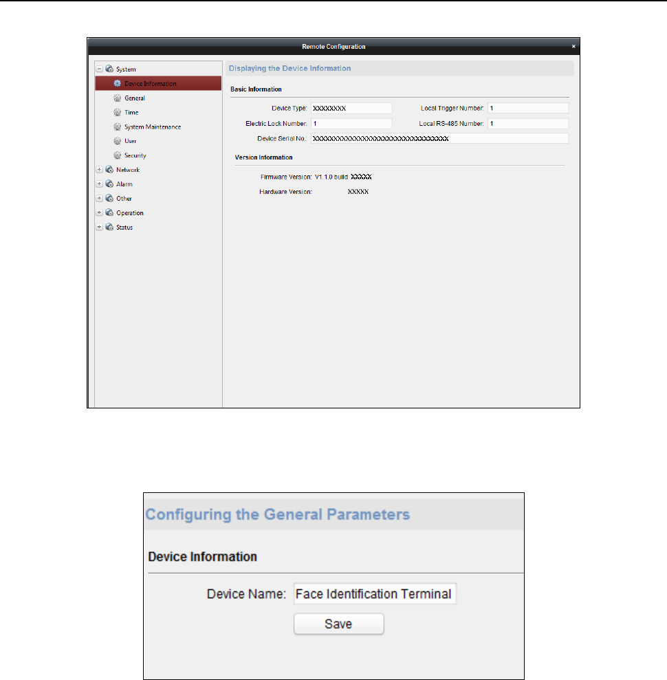
Face Recognition Terminal User Manual
65
Editing Device Name
In the Remote Configuration interface, click System -> General to configure the device name and
overwrite record files parameter. Click Save to save the settings.
Editing Time
Steps:
1. In the Remote Configuration interface, click System -> Time to configure the time zone.
2. (Optional) Check Enable NTP and configure the NTP server address, the NTP port, and the
synchronization interval.
3. (Optional) Check Enable DST and configure the DST star time, end time and the bias.
4. Click Save to save the settings.
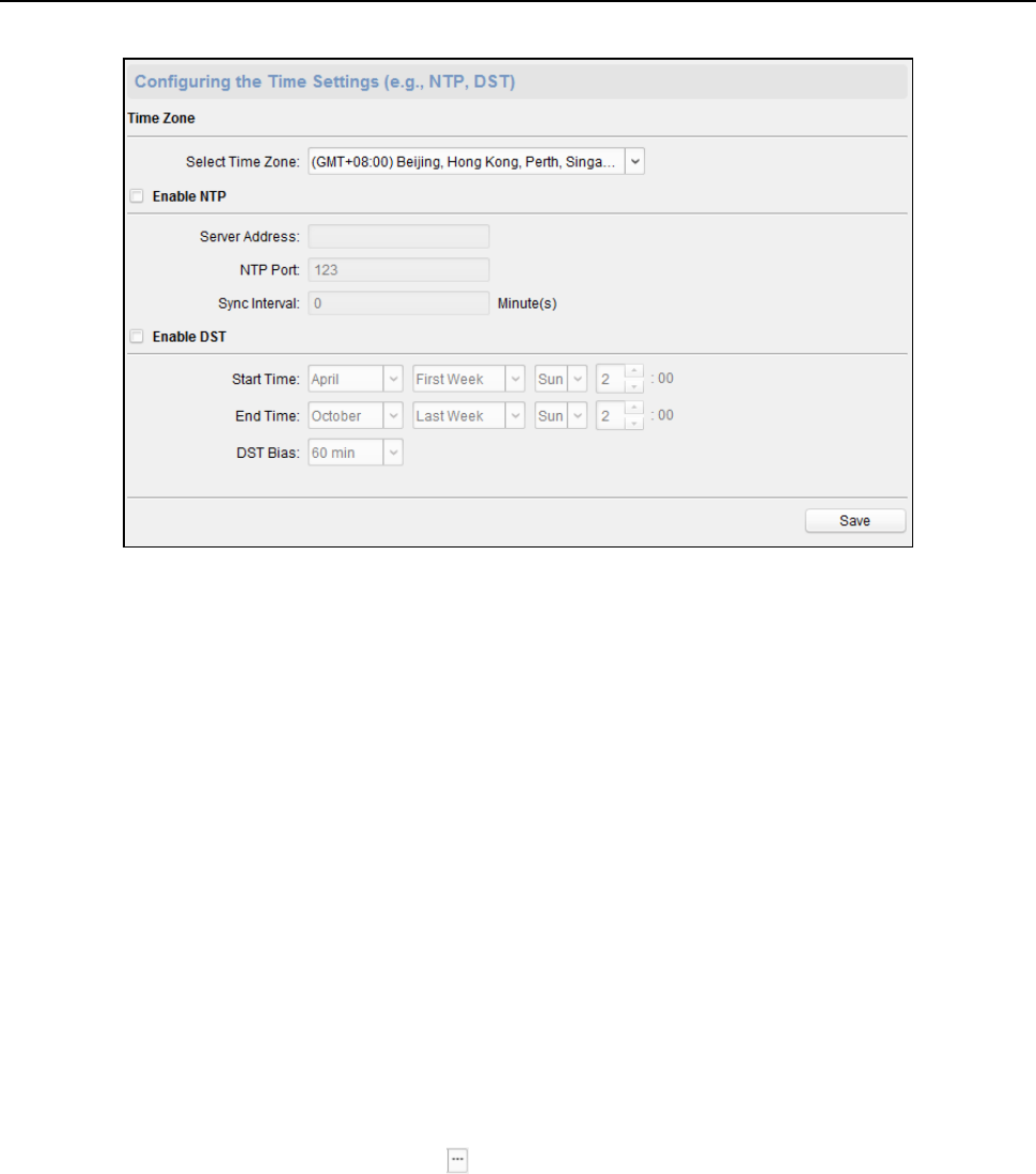
Face Recognition Terminal User Manual
66
Setting System Maintenance
Purpose:
You can reboot the device remotely, restore the device to default settings, import configuration file,
upgrade the device, etc.
Steps:
1. In the Remote Configuration interface, click System -> System Maintenance.
2. Click Reboot to reboot the device.
Or click Restore Default Settings to restore the device settings to the default ones, excluding
the IP address.
Or click Restore All to restore the device parameters to the default ones. The device should be
activated after restoring.
Note: The configuration file contains the device parameters.
Or click Import Configuration File to import the configuration file from the local PC to the
device.
Or click Export Configuration File to export the configuration file from the device to the local
PC
Note: The configuration file contains the device parameters.
3. You can also remote upgrade the device.
1) In the Remote Upgrade part, click to select the upgrade file.
2) Click Upgrade to start upgrading.
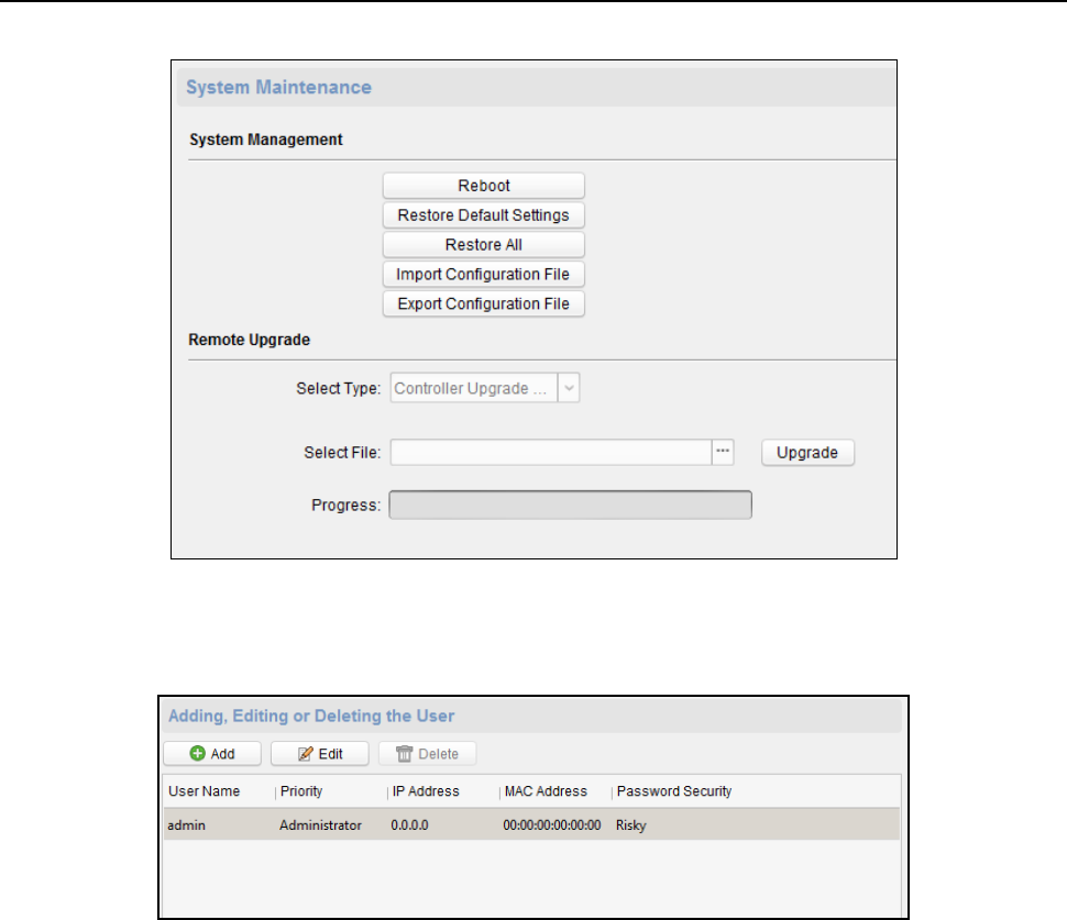
Face Recognition Terminal User Manual
67
Managing User
Steps:
1. In the Remote Configuration interface, click System -> User.
2. Click Add to add the user (Do not support by the elevator controller.).
Or select a user in the user list and click Edit to edit the user. You are able to edit the user
password, the IP address, the MAC address and the user permission. Cilck OK to confirm
editing.
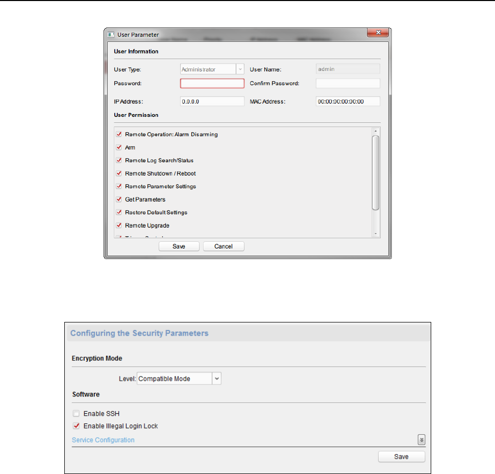
Face Recognition Terminal User Manual
68
Setting Security
Steps:
1. Click System -> Security.
2. Select the encryption mode in the dropdown list.
You can select Compatible Mode or Encryption Mode.
3. Click Save to save the settings.
Configuring Network Parameters
Click Network -> General. You can configure the NIC type, the IPv4 address, the subnet mask (IPv4),
the default gateway (IPv4), MTU address, MTU, and the device port. Click Save to save the settings.
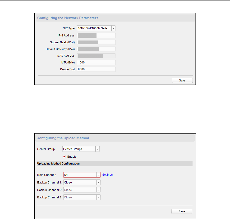
Face Recognition Terminal User Manual
69
Configuring Upload Method
Purpose
:
You can set the center group for uploading the log via the EHome protocol.
Steps:
1. Click Network -> Report Strategy.
2. Select a Center Group from the drop-down list.
3. Check the Enable check box.
4. Set the uploading method.
You can set the main channel and the backup channel.
5. Click Settings on the right of the channel field to set the detailed information.
6. Click Save to save the settings.
Configuring Network Center
You can set the notify surveillance center, center’s IP address, the port No., the Protocol (EHome),
and the EHome account user name to transmit data via EHome protocol. For details about EHome
protocol’s transmission, refer to Network Center Settings in Chapter 6.3.4 Network Settings. Click
Save to save the settings or click
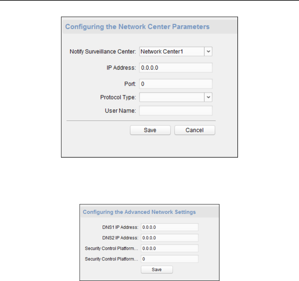
Face Recognition Terminal User Manual
70
Configuring Advanced Network
Click Network -> Advanced Settings. You can configure the DNS IP address 1, the DNS IP address 2,
the security control platform IP, and the security control platform port. Click Save to save the
settings.
Configuring Wi-Fi
Steps:
1. Click Network –> Wi-Fi.
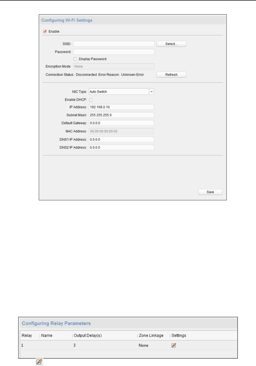
Face Recognition Terminal User Manual
71
2. Check Enable to enable the Wi-Fi function.
3. Input the hot spot name.
Or you can click Select… to select a network.
4. Input the Wi-Fi password.
5. (Optional) Click Refresh to refresh the network status.
6. (Optional) Select the NIC Type.
7. (Optional) Select to uncheck Enable DHCP and set the IP address, the subnet mask, the default
gateway, the MAC address, the DNS1 IP Address, and the DNS2 IP address.
8. Click Save to save the settings.
Configuring Relay Parameters
Steps:
1. Click Alarm -> Relay.
You can view the relay parameters.
2. Click the to pop up the Relay Parameters Settings window.
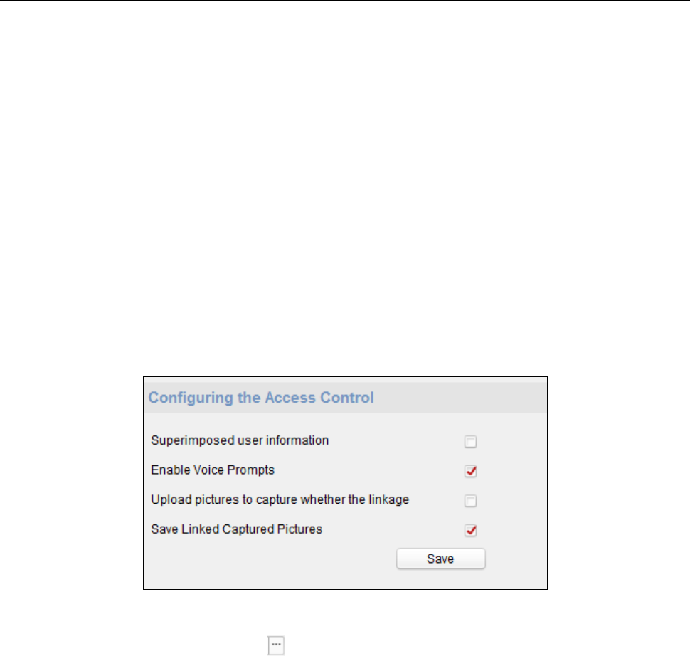
Face Recognition Terminal User Manual
72
3. Set the relay name and the output delay.
4. Click Save to save the paramters.
Or click Copy to… to copy the relay information to other relays.
Configuring Access Control Parameters
Steps:
1. In the Remote Configuration interface, click Other -> Access Control Parameters.
2. Select and check the item as you desired.
Overlay User Information on Picture: Display the user infomration on the captured picture.
Enable Voice Prompt: If check the checkbox, the voicce pormpt is enabled in the device.
You can hear the voice prompt when operating in the device.
Upload Pictures after Capturing: If check the checkbox, the pictures captured by linked
camera will be upload to the system automatically.
Save Captured Pictures: If you check the checkbox, you can save the picture capured by
linked camera to the device. You can view the picture in 6.9 Searching Access Control Event.
3. Click Save to save the settings.
Uploading Background Picture
Click Other -> Picture Upload. Click to select the picture from the local. You can also click
Preview to preview the picture. Click Upload to upload the picture.
Note: The function should be supported by the device.
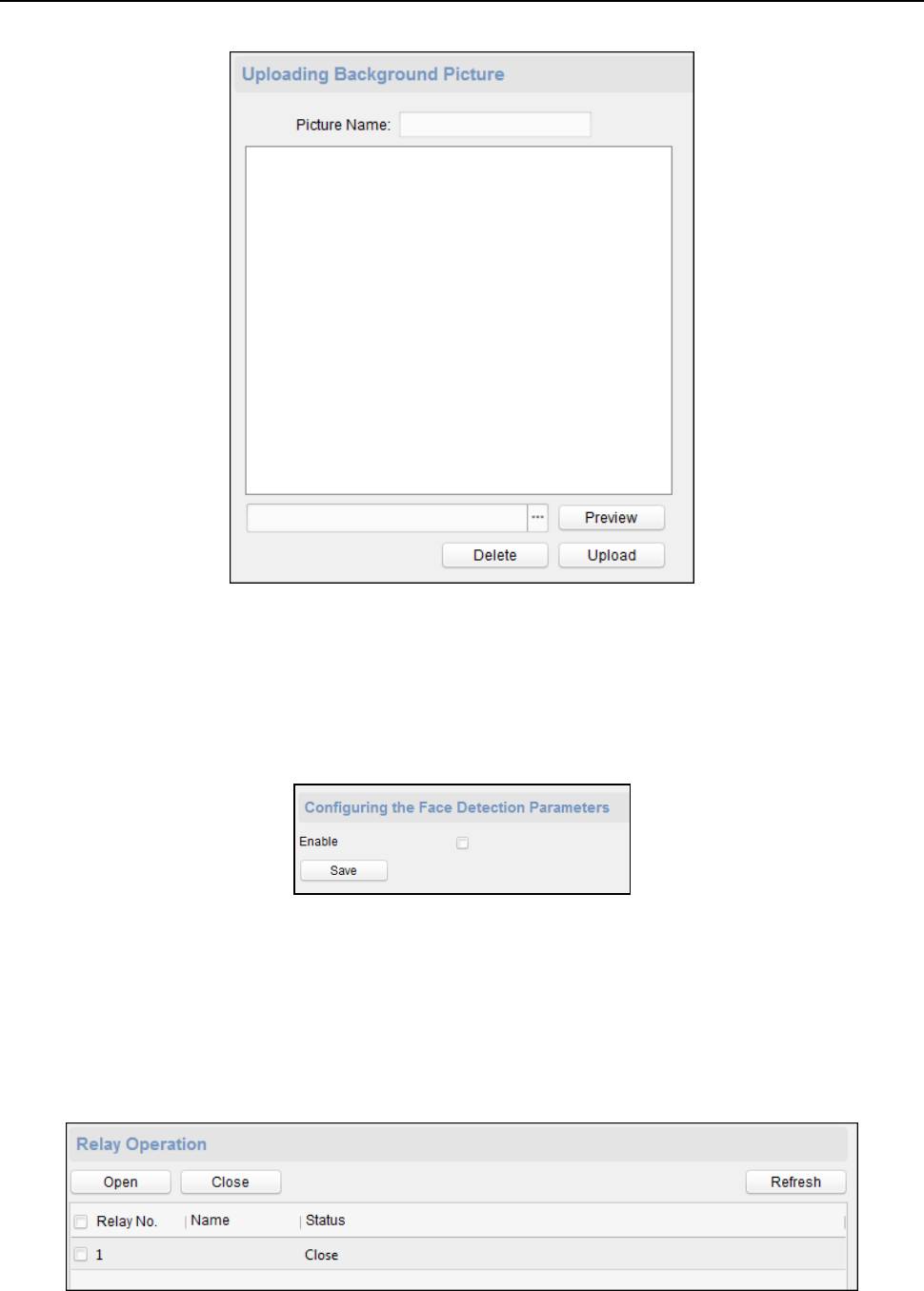
Face Recognition Terminal User Manual
73
Configuring Face Detection Parameters
Click Other -> Face Detection. You can check the Enable checkbox to enable the device face
detection function.
After you enable the function, the device should detect the face while authenticating. Or the
authentication will be failed.
Note: Only devices with video function support this function.
Operating Relay
Steps:
1. Click Operation -> Relay.
You can view the relay status.
2. Check the relay checkbox
3. Click Open or Close to open/close the relay.
4. (Optional) Click Refresh to refresh the relay status.
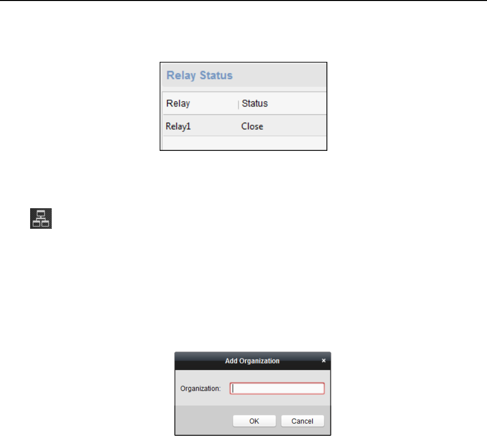
Face Recognition Terminal User Manual
74
Viewing Relay Status
Click Status -> Relay to view the relay status.
6.4 Organization Management
You can add, edit, or delete the organization as desired.
Click tab to enter the Person and Card Management interface.
6.4.1 Adding Organization
Steps:
1. In the organization list on the left, you should add a top organization as the parent organization
of all organizations.
Click Add button to pop up the adding organization interface.
2. Input the Organization Name as desired.
3. Click OK to save the adding.
4. You can add multiple levels of organizations according to the actual needs.
To add sub organizations, select the parent organization and click Add.
Repeat Step 2 and 3 to add the sub organization.
Then the added organization will be the sub-organization of the upper-level organization.
Note: Up to 10 levels of organizations can be created.
6.4.2 Modifying and Deleting Organization
You can select the added organization and click Modify to modify its name.
You can select an organization, and click Delete button to delete it.
Notes:
The lower-level organizations will be deleted as well if you delete an organization.
Make sure there is no person added under the organization, or the organization cannot be
deleted.
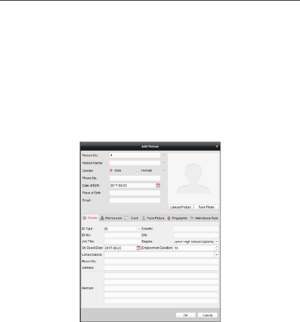
Face Recognition Terminal User Manual
75
6.5 Person Management
After adding the organization, you can add person to the organization and manage the added
person such as issuing cards in batch, importing and exporting person information in batch, etc.
Note: Up to 10,000 persons or cards can be added.
6.5.1 Adding Person
Adding Person (Basic Information)
Steps:
1. Select an organization in the organization list and click Add button on the Person panel to pop
up the adding person dialog.
2. The Person No. will be generated automatically and is not editable.
3. Input the basic information including person name, gender, phone No., birthday details, and
email address.
4. Click Upload Picture to select the person picture from the local PC to upload it to the client.
Note: The picture should be in *.jpg format.
5. (Optional) You can also click Take Phone to take the person’s photo with the PC camera.
6. Click OK to finish adding.
Adding Person (Detailed Information)
Steps:
1. In the Add Person interface, click Details tab.
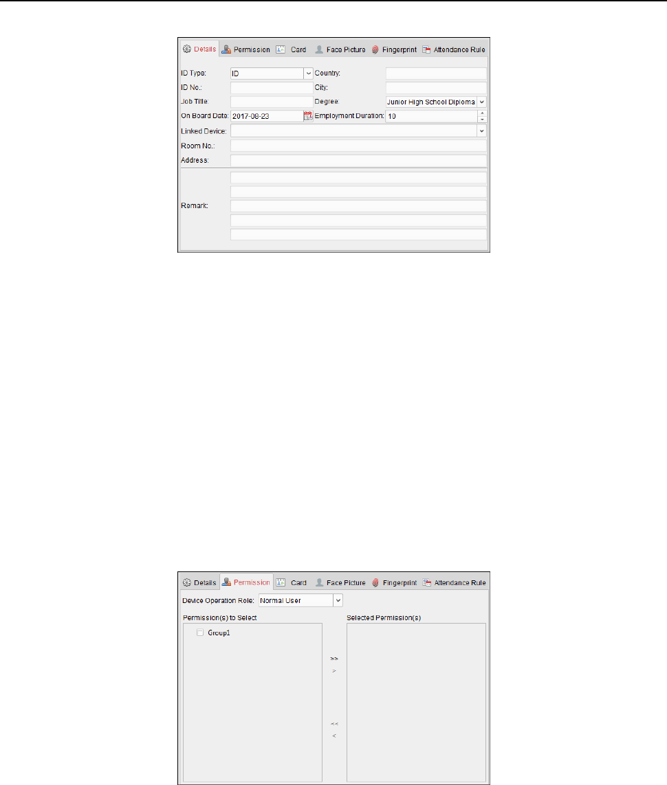
Face Recognition Terminal User Manual
76
2. Input the detailed information of the person, including person’s ID type, ID No., country, etc.,
according to actual needs.
Linked Device: You can bind the indoor station to the person.
Note: If you select Analog Indoor Station in the Linked Device, the Door Station field will
display and you are required to select the door station to communicate with the analog
indoor station.
Room No.: You can input the room No. of the person.
3. Click OK to save the settings.
Adding Person (Permission)
You can assign the permissions (including operation permissions of access control device and
access control permissions) to the person when adding person.
Note: For setting the access control permission, refer to Chapter 6.7 Permission Configuration.
Steps:
1. In the Add Person interface, click Permission tab.
2. In the Device Operation Role field, select the role of operating the access control device.
Normal User: The person has the permission to check-in/out on the device, pass the access
control point, etc.
Administrator: The person has the normal user permission, as well as permission to configure
the device, including adding normal user, etc.
3. In the Permission(s) to Select list, all the configured permissions display.
Check the permission(s) checkbox(es) and click > to add to the Selected Permission(s) list.
(Optional) You can click >> to add all the displayed permissions to the Selected Permission(s)
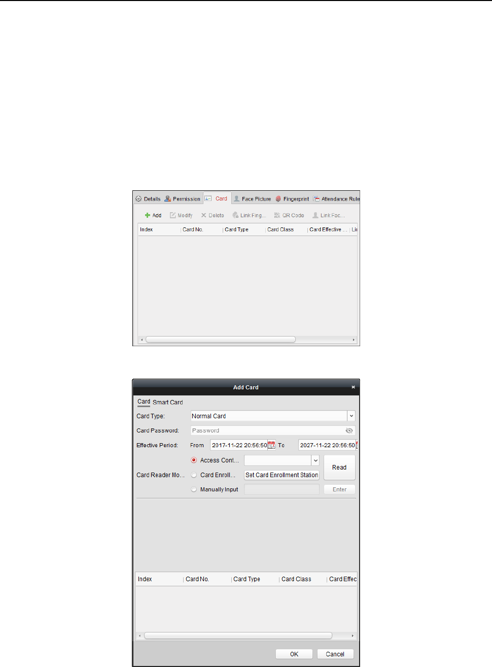
Face Recognition Terminal User Manual
77
list.
(Optional) In the Selected Permission(s) list, select the selected permission and click < to
remove it. You can also click << to remove all the selected permissions.
4. Click OK to save the settings.
Adding Person (Card)
You can add card and issue the card to the person.
Adding General Card
Steps:
1. In the Add Person interface, click Card tab.
2. Click Add to pop up the Add Card dialog.
3. Click Card to enter the Card tab.
4. Select the card type according to actual needs.
Normal Card
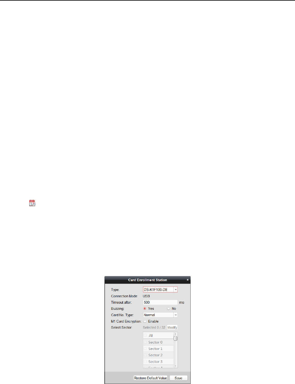
Face Recognition Terminal User Manual
78
Card for Disabled Person: The door will remain open for the configured time period for the
card holder.
Card in Blacklist: The card swiping action will be uploaded and the door cannot be opened.
Patrol Card: The card swiping action can used for checking the working status of the
inspection staff. The access permission of the inspection staff is configurable.
Duress Card: The door can open by swiping the duress card when there is duress. At the
same time, the client can report the duress event.
Super Card: The card is valid for all the doors of the controller during the configured
schedule.
Visitor Card: The card is assigned for visitors. For the Visitor Card, you can set the Max.
Swipe Times.
Note: The Max. Swipe Times should be between 0 and 255. When setting as 0, it means
the card swiping is unlimited.
5. Input the password of the card itself in the Card Password field. The card password should
contain 4 to 8 digits.
Note: The password will be required when the card holder swiping the card to get enter to or
exit from the door if you enable the card reader authentication mode as Card and Password,
Password and Fingerprint, and Card, Password, and Fingerprint. For details, Chapter 6.8.2
Card Reader Authentication.
6. Click to set the effective time and expiry time of the card.
7. Select the Card Reader Mode for reading the card No.
Access Controller Reader: Place the card on the reader of the Access Controller and click
Read to get the card No.
Card Enrollment Station: Place the card on the Card Enrollment Station and click Read to
get the card No.
Note: The Card Enrollment Station should connect with the PC running the client. You can
click Set Card Enrollment Station to enter the following dialog.
1) Select the Card Enrollment Station type.
Note: Currently, the supported card reader types include DS-K1F100-D8, DS-K1F100-M,
DS-K1F100-D8E, and DS-K1F180-D8E.
2) Set the serial port No., the baud rate, the timeout value, the buzzing, or the card No.

Face Recognition Terminal User Manual
79
type.
If the card is M1 card, and if you need to enable the M1 Card Encryption function, you
should check Enable checkbox of M1 Card Encryption and click Modify to select the
sector.
3) Click Save button to save the settings.
You can click Restore Default Value button to restore the defaults.
Manually Input: Input the card No. and click Enter to input the card No.
8. Click OK and the card(s) will be issued to the person.
9. (Optional) You can select the added card and click Modify or Delete to edit or delete the card.
10. (Optional) You can generate and save the card QR code for QR code authentication.
1) Select an added card and click QR Code to generate the card QR code.
2) In the QR code pop-up window, click Download to save the QR code to the local PC.
You can print the QR code for authentication on the specified device.
Note: The device should support the QR code authentication function. For details about
setting the QR code authentication function, see the specified device user manual.
11. (Optional) You can click Link Fingerprint to link the card with the person’s fingerprint, so that
the person can place the finger on the scanner instead of swiping card when passing the door.
12. (Optional) You can click Link Face Picture to link the card with the face picture, so that the
person can pass the door by scanning the face via the device instead of swiping card when
passing the door.
13. Click OK to save the settings.
Adding Smart Card
Purpose:
You can store fingerprints and ID card infomration in the smart card. When authenticating, after
swiping the smart card on the device, you can scan your fingerprint or swipe your ID card on the
device. The device will compare the fingerperint or ID card information in the smart card with the
ones collected. If you use the smart card for authentication, there is no need to store the
fingerprints or ID card information in the device in advance.
Steps:
1. In the Add Person page, set the person basic information.
2. Click Card to enter the card tab.
3. Click Add to pop up the Add Card dialog.
4. Click Smart Card to enter the Smart Card tab.
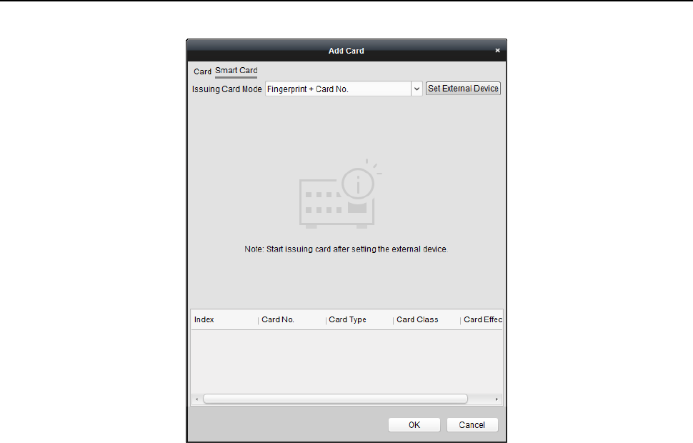
Face Recognition Terminal User Manual
80
5. Select an issuing card mode from the dropdown list.
6. Set the external device.
1) Click Set External Device to enter the Set External Device page.
2) (Optional) Select the issuing card mode again.
3) Set a card enrollment station.
4) If you select “Fingerprint + Card No.” as the issuing mode, set the fingerprint recorder
model.
If you select “ID Card No. + Card No.” as the issuing mode, set the ID card reader model.
If you select “Fingerprint + ID Card No. + Card No.” as the issuing mode, set the fingerprint
recorder model and the ID card reader model.
5) Click OK save the settings.
7. Select a card type for the smart card.
Normal Card
Card for Disabled Person: The door will remain open for the configured time period for the
card holder.
Card in Blacklist: The card swiping action will be uploaded and the door cannot be opened.
Patrol Card: The card swiping action can used for checking the working status of the
inspection staff. The access permission of the inspection staff is configurable.
Duress Card: The door can open by swiping the duress card when there is duress. At the
same time, the client can report the duress event.
Super Card: The card is valid for all the doors of the controller during the configured
schedule.
Visitor Card: The card is assigned for visitors. For the Visitor Card, you can set the Max.
Swipe Times.
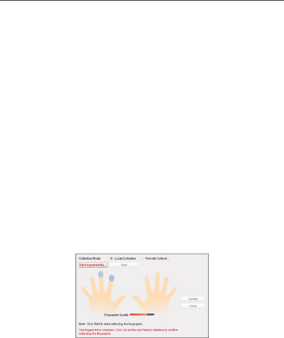
Face Recognition Terminal User Manual
81
Note: The Max. Swipe Times should be between 0 and 255. When setting as 0, it means
the card swiping is unlimited.
Dismiss Card: Swipe the card to dismiss alarm.
8. Set other parameters of the card.
1) Set the card password.
2) Set the card effective date.
3) Scan your fingerprint and swipe your ID card according to the promt.
4) Swipe the smart card.
The added card information will display in the list below.
9. Click OK and the card(s) will be issued to the person.
10. (Optional) Select the added card and click Modify or Delete to edit or delete the card.
11. (Optional) Generate and save the card QR code for QR code authentication.
1) Select an added card and click QR Code to generate the card QR code.
2) In the QR code pop-up window, click Download to save the QR code to the local PC.
You can print the QR code for authentication on the specified device.
Note: The device should support the QR code authentication function. For details about
setting the QR code authentication function, see the specified device user manual.
12. (Optional) Click Link Fingerprint to link the card with the person’s fingerprint, so that the
person can place the finger on the scanner instead of swiping card when passing the door.
13. (Optional) Click Link Face Picture to link the card with the face picture, so that the person can
pass the door by scanning the face via the device instead of swiping card when passing the
door.
14. Click OK to save the settings.
Adding Person (Fingerprint)
Steps:
1. In the Add Person interface, click Fingerprint tab.
2. Select Local Collection as desired.
3. Before inputting the fingerprint, you should connect the fingerprint machine to the PC and set
its parameters first.
Click Set Fingerprint Machine to enter the following dialog box.

Face Recognition Terminal User Manual
82
1) Select the device type.
Currently, the supported fingerprint machine types include DS-K1F800-F, DS-K1F810-F,
DS-K1F820-F, and DS-K1F181-F.
2) For fingerprint machine type DS-K1F800-F, you can set the serial port number, baud rate,
and overtime parameters of the fingerprint machine.
3) Click Save button to save the settings.
You can click Restore Default Value button to restore the default settings.
Notes:
The serial port number should correspond to the serial port number of PC. You can check
the serial port number in Device Manager in your PC.
The baud rate should be set according to the external fingerprint card reader. The default
value is 19200.
Timeout after field refers to the valid fingerprint collecting time. If the user does not input
a fingerprint or inputs a fingerprint unsuccessfully, the device will indicate that the
fingerprint collecting is over.
4. Click Start button, click to select the fingerprint to start collecting.
5. Lift and rest the corresponding fingerprint on the fingerprint scanner twice to collect the
fingerprint to the client.
6. (Optional) You can also click Remote Collection to collect fingerprint from the device.
Note: The function should be supported by the device.
7. (Optional) You can select the registered fingerprint and click Delete to delete it.
You can click Clear to clear all fingerprints.
8. Click OK to save the fingerprints.
Adding Person (Attendance Rule)
You can set the attendance rule for the person.
Note: This tab page will display when you select Non-Residence mode in the application scene
when running the software for the first time.
Steps:
1. In the Add Person interface, click Attendance Rule tab.
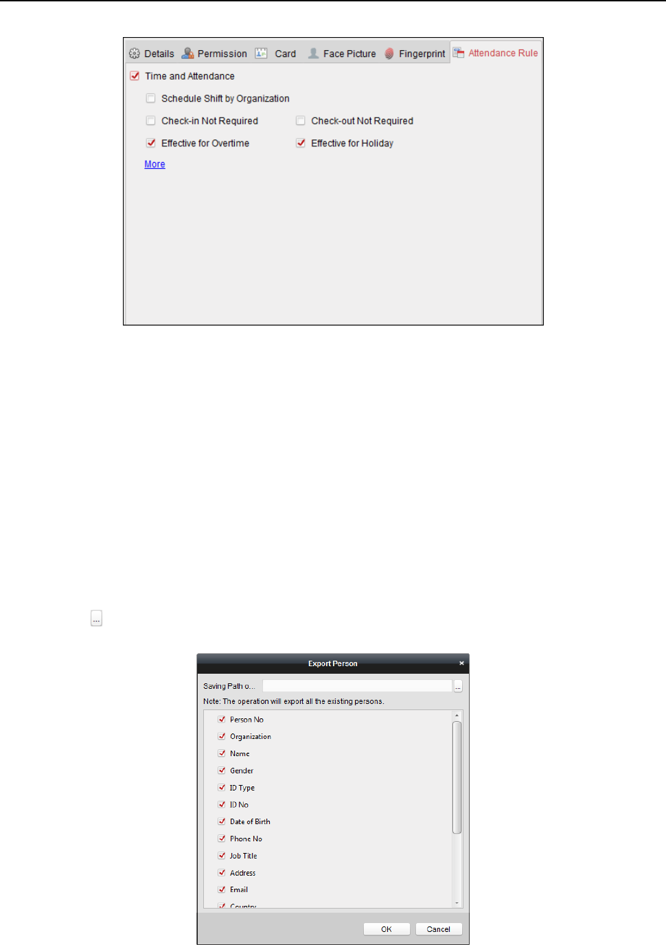
Face Recognition Terminal User Manual
83
2. If the person joins in the time and attendance, check the Time and Attendance checkbox to
enable this function for the person. Then the person’s card swiping records will be recorded
and analyzed for time and attendance.
For details about Time and Attendance, click More to go to the Time and Attendance module.
3. Click OK to save the settings.
Importing and Exporting Person Information
The person information can be imported and exported in batch.
Steps:
1. Exporting Person: You can export the added persons’ information in Excel format to the local
PC.
1) After adding the person, you can click Export Person button in the Person and Card tab to
pop up the following dialog.
2) Click to select the path of saving the exported Excel file.
3) Check the checkboxes to select the person information to export.
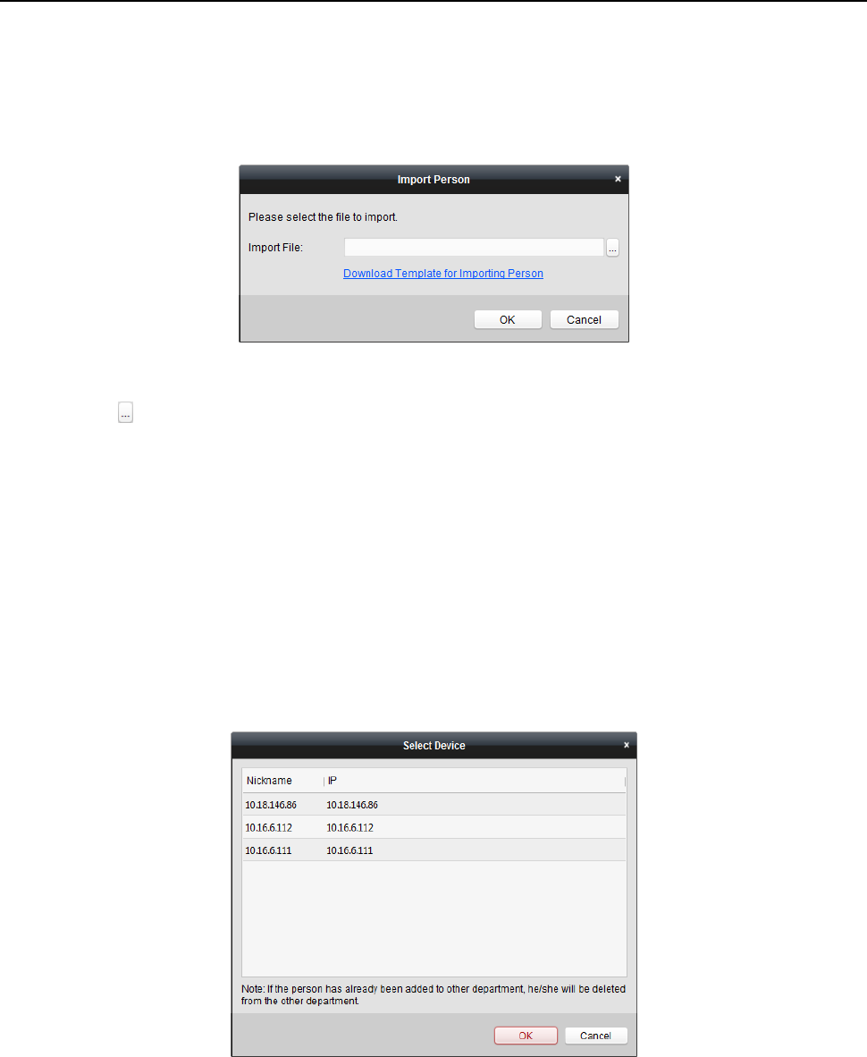
Face Recognition Terminal User Manual
84
4) Click OK to start exporting.
2. Importing Person: You can import the Excel file with persons information in batch from the
local PC
1) click Import Person button in the Person and Card tab.
2) You can click Download Template for Importing Person to download the template first.
3) Input the person information to the downloaded template.
4) Click to select the Excel file with person information.
5) Click OK to start importing.
Getting Person Information from Access Control Device
If the added access control device has been configured with person information (including person
details, fingerprint, issued card information), you can get the person information from the device
and import to the client for further operation.
Note: This function is only supported by the device the connection mothod of which is TCP/IP
when adding the device.
Steps:
1. In the organization list on the left, click to select an organization to import the persons.
2. Click Get Person button to pop up the following dialog box.
3. The added access control device will be displayed.
4. Click to select the device and then click OK to start getting the person information from the
device.
You can also double click the device name to start getting the person information.
Notes:
The person information, including person details, person’s fingerprint information (if
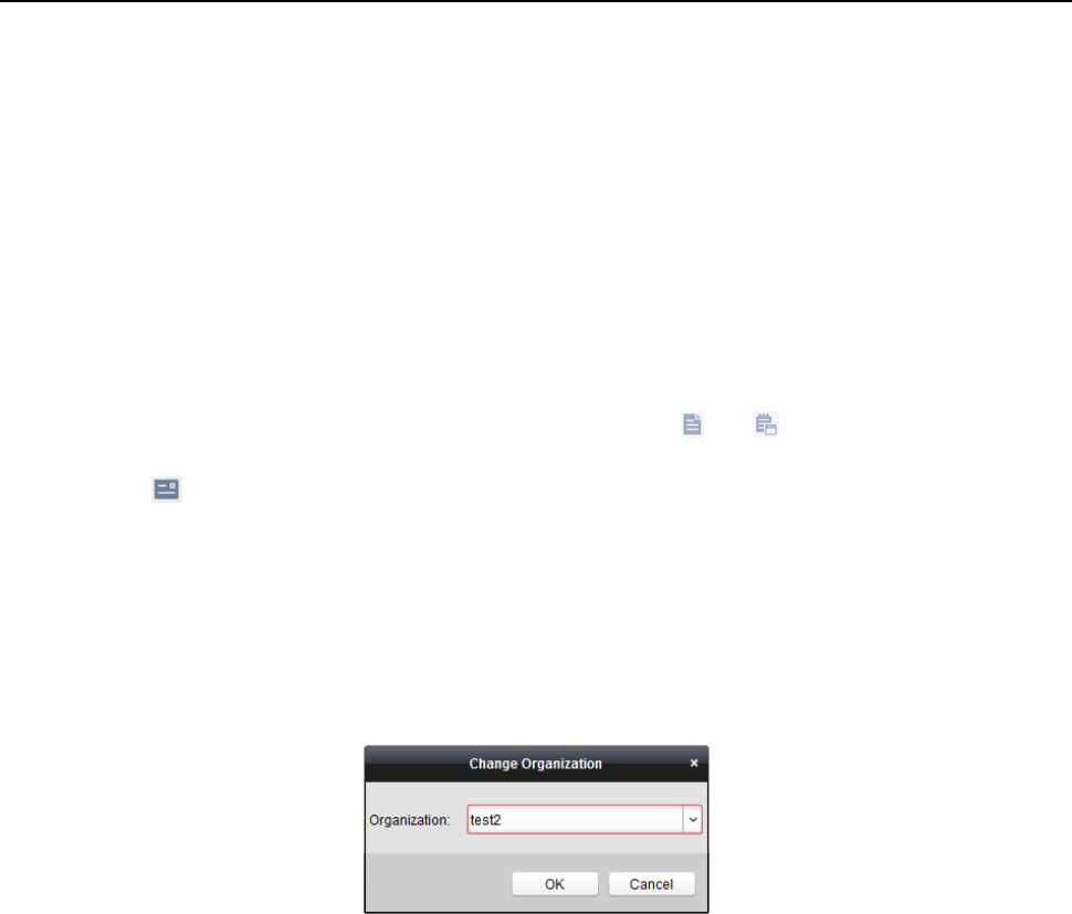
Face Recognition Terminal User Manual
85
configured), and the linked card (if configured), will be imported to the selected organization.
If the person name stored in the device is empty, the person name will be filled with the issued
card No. after importing to the client.
The gender of the persons will be Male by default.
Up to 10000 persons can be imported.
6.5.2 Managing Person
Modifying and Deleting Person
To modify the person information and attendance rule, click or in the Operation column,
or select the person and click Modify to open the editing person dialog.
You can click to view the person’s card swiping records.
To delete the person, select a person and click Delete to delete it.
Note: If a card is issued to the current person, the linkage will be invalid after the person is deleted.
Changing Person to Other Organization
You can move the person to another organization if needed.
Steps:
1. Select the person in the list and click Change Organization button.
2. Select the organization to move the person to.
3. Click OK to save the settings.
Searching Person
You can input the keyword of card No. or person name in the search field, and click Search to
search the person.
You can input the card No. by clicking Read to get the card No. via the connected card enrollment
station.
You can click Set Card Enrollment Station in the dropdown list to set the parameters.
6.5.3 Issuing Card in Batch
You can issue multiple cards for the person with no card issued in batch.
Steps:
1. Click Issue Card in Batch button to enter the following dialog.
All the added person with no card issued will display in the Person(s) with No Card Issued list.
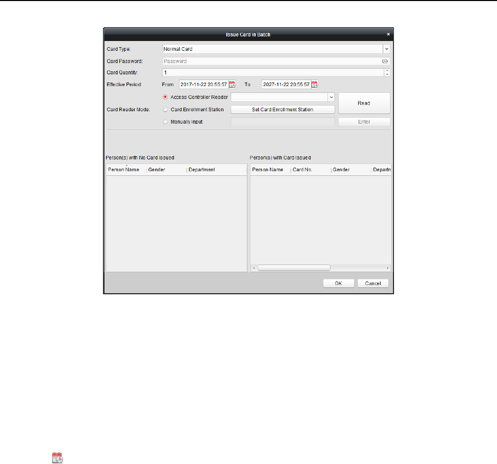
Face Recognition Terminal User Manual
86
2. Select the card type according to actual needs.
Note: For details about the card type, refer to Adding Person.
3. Input the password of the card itself in the Card Password field. The card password should
contain 4 to 8 digits.
Note: The password will be required when the card holder swiping the card to get enter to or
exit from the door if you enable the card reader authentication mode as Card and Password,
Password and Fingerprint, and Card, Password, and Fingerprint. For details, refer to Chapter
6.8.2 Card Reader Authentication.
4. Input the card quantity issued for each person.
For example, if the Card Quantity is 3, you can read or enter three card No. for each person.
5. Click to set the effective time and expiry time of the card.
6. In the Person(s) with No Card Issued list on the left, select the person to issue card.
Note: You can click on the Person Name, Gender, and Department column to sort the persons
according to actual needs.
7. Select the Card Reader Mode for reading the card No.
Access Controller Reader: Place the card on the reader of the Access Controller and click
Read to get the card No.
Card Enrollment Station: Place the card on the Card Enrollment Station and click Read to
get the card No.
Note: The Card Enrollment Station should connect with the PC running the client. You can
click Set Card Enrollment Station to enter the following dialog.
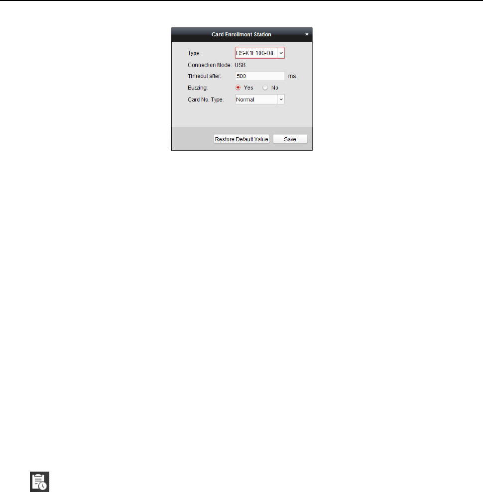
Face Recognition Terminal User Manual
87
1) Select the Card Enrollment Station type.
Note: Currently, the supported card reader types include DS-K1F100-D8, DS-K1F100-M,
DS-K1F100-D8E, and DS-K1F180-D8E.
2) Set the parameters about the connected card enrollment station.
If the card is M1 card, and if you need to enable the M1 Card Encryption function, you
should check Enable checkbox of M1 Card Encryption and click Modify to select the
sector.
3) Click Save button to save the settings.
You can click Restore Default Value button to restore the defaults.
Manually Input: Input the card No. and click Enter to input the card No.
8. After issuing the card to the person, the person and card information will display in the
Person(s) with Card Issued list.
9. Click OK to save the settings.
6.6 Schedule and Template
Purpose:
You can configure the template including week schedule and holiday schedule. After setting the
templates, you can adopt the configured templates to access control permissions when setting the
permission, so that the access control permission will take effect in the time durations of the
template.
Click to enter the schedule and template interface.
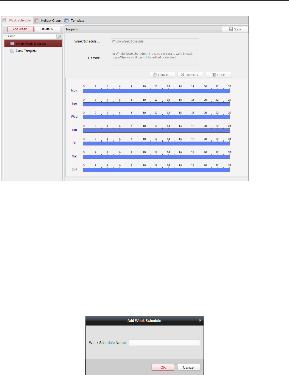
Face Recognition Terminal User Manual
88
You can manage the schedule of access control permission including Week Schedule, Holiday
Schedule, and Template. For permission settings, please refer to Chapter 6.7 Permission
Configuration.
6.6.1 Week Schedule
Click Week Schedule tab to enter the Week Schedule Management interface.
The client defines two kinds of week plan by default: Whole Week Schedule and Blank Schedule,
which cannot be deleted and edited.
Whole Week Schedule: Card swiping is valid on each day of the week.
Blank Schedule: Card swiping is invalid on each day of the week.
You can perform the following steps to define custom schedules on your demand.
Steps:
1. Click Add Week Schedule button to pop up the adding schedule interface.
2. Input the name of week schedule and click OK button to add the week schedule.
3. Select the added week schedule in the schedule list and you can view its property on the right.
You can edit the week schedule name and input the remark information.
4. On the week schedule, click and drag on a day to draw on the schedule, which means in that
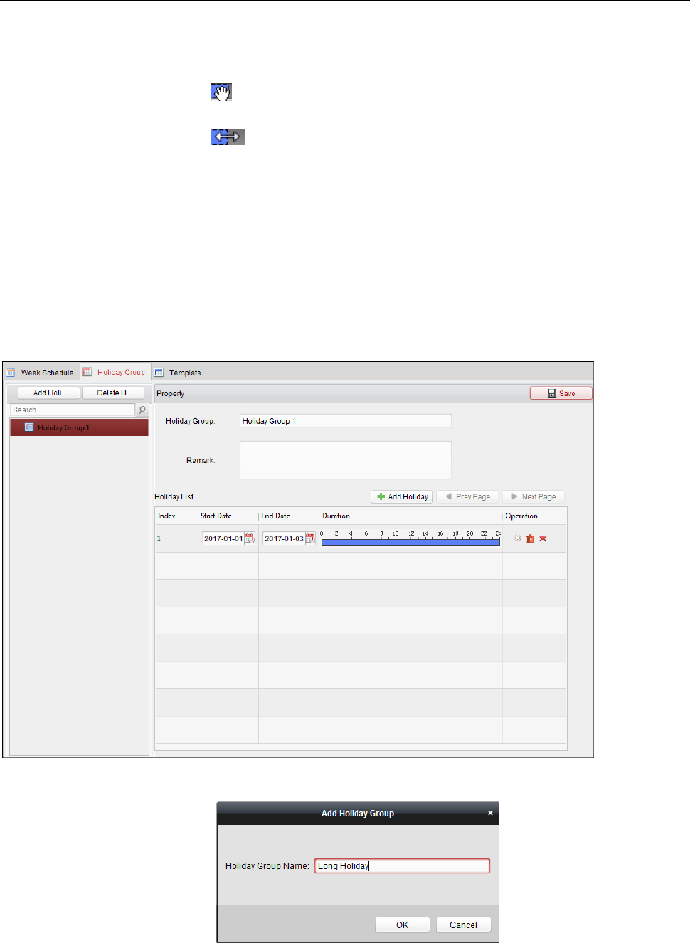
Face Recognition Terminal User Manual
89
period of time, the configured permission is activated.
Note: Up to 8 time periods can be set for each day in the schedule.
5. When the cursor turns to , you can move the selected time bar you just edited. You can also
edit the displayed time point to set the accurate time period.
When the cursor turns to , you can lengthen or shorten the selected time bar.
6. Optionally, you can select the schedule time bar,
and then click Delete Duration to delete the selected time bar,
or click Clear to delete all the time bars,
or click Copy to Week to copy the time bar settings to the whole week.
7. Click Save to save the settings.
6.6.2 Holiday Group
Click Holiday Group tab to enter the Holiday Group Management interface.
Steps:
1. Click Add Holiday Group button on the left to pop up the adding holiday group interface.
2. Input the name of holiday group in the text filed and click OK button to add the holiday group.
3. Select the added holiday group and you can edit the holiday group name and input the remark
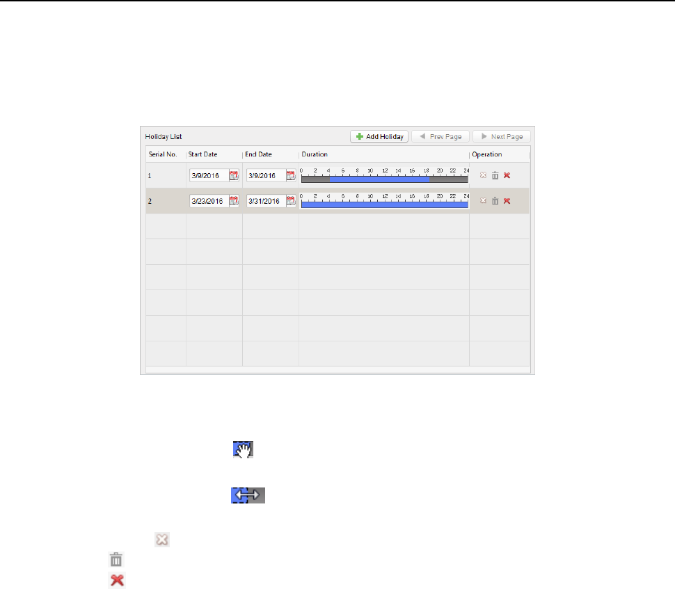
Face Recognition Terminal User Manual
90
information.
4. Click Add Holiday icon on the right to add a holiday period to the holiday list and configure the
duration of the holiday.
Note: Up to 16 holidays can be added to one holiday group.
1) On the period schedule, click and drag to draw the period, which means in that period of
time, the configured permission is activated.
Note: Up to 8 time durations can be set for each period in the schedule.
2) When the cursor turns to , you can move the selected time bar you just edited. You can
also edit the displayed time point to set the accurate time period.
3) When the cursor turns to , you can lengthen or shorten the selected time bar.
4) Optionally, you can select the schedule time bar,
and then click to delete the selected time bar,
or click to delete all the time bars of the holiday,
or click to delete the holiday directly.
5. Click Save to save the settings.
Note: The holidays cannot be overlapped with each other.
6.6.3 Template
After setting the week schedule and holiday group, you can configure the template which contains
week schedule and holiday group schedule.
Note: The priority of holiday group schedule is higher than the week schedule.
Click Template tab to enter the Template Management interface.
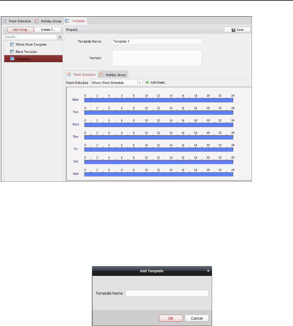
Face Recognition Terminal User Manual
91
There are two pre-defined templates by default: Whole Week Template and Blank Template,
which cannot be deleted and edited.
Whole Week Template: The card swiping is valid on each day of the week and it has no holiday
group schedule.
Blank Template: The card swiping is invalid on each day of the week and it has no holiday
group schedule.
You can define custom templates on your demand.
Steps:
1. Click Add Template to pop up the adding template interface.
2. Input the template name in the text filed and click OK button to add the template.
3. Select the added template and you can edit its property on the right. You can edit the template
name and input the remark information.
4. Select a week schedule to apply to the schedule.
Click Week Schedule tab and select a schedule in the dropdown list.
You can also click Add Week Schedule to add a new week schedule. For details, refer to
Chapter 6.6.1 Week Schedule.

Face Recognition Terminal User Manual
92
5. Select holiday groups to apply to the schedule.
Note: Up to 4 holiday groups can be added.
Click to select a holiday group in the list and click Add to add it to the template. You can also
click Add Holiday Group to add a new one. For details, refer to Chapter 6.6.2 Holiday Group.
You can click to select an added holiday group in the right-side list and click Delete to delete it.
You can click Clear to delete all the added holiday groups.
6. Click Save button to save the settings.
6.7 Permission Configuration
In Permission Configuration module, you can add, edit, and delete the access control permission,
and then apply the permission settings to the device to take effect.
Click icon to enter the Access Control Permission interface.
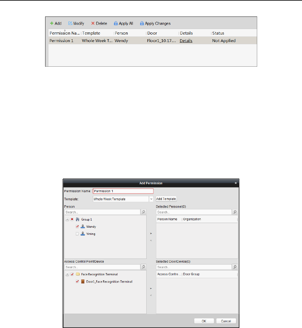
Face Recognition Terminal User Manual
93
6.7.1 Adding Permission
Purpose:
You can assign permission for persons to enter/exist the access control points (doors) in this
section.
Notes:
You can add up to 4 permissions to one access control point of one device.
You can add up to 128 permissions in total.
Steps:
1. Click Add icon to enter following interface.
2. In the Permission Name field, input the name for the permission as desired.
3. Click on the dropdown menu to select a template for the permission.
Note: You should configure the template before permission settings. You can click Add
Template button to add the template. Refer to Chapter 6.6 Schedule and Template for details.
4. In the Person list, all the added persons display.
Check the checkbox(es) to select person(s) and click > to add to the Selected Person list.
(Optional) You can select the person in Selected Person list and click < to cancel the selection.
5. In the Access Control Point/Device list, all the added access control points (doors) and door
stations will display.
Check the checkbox(es) to select door(s) or door station(s) and click > to add to the selected
list.
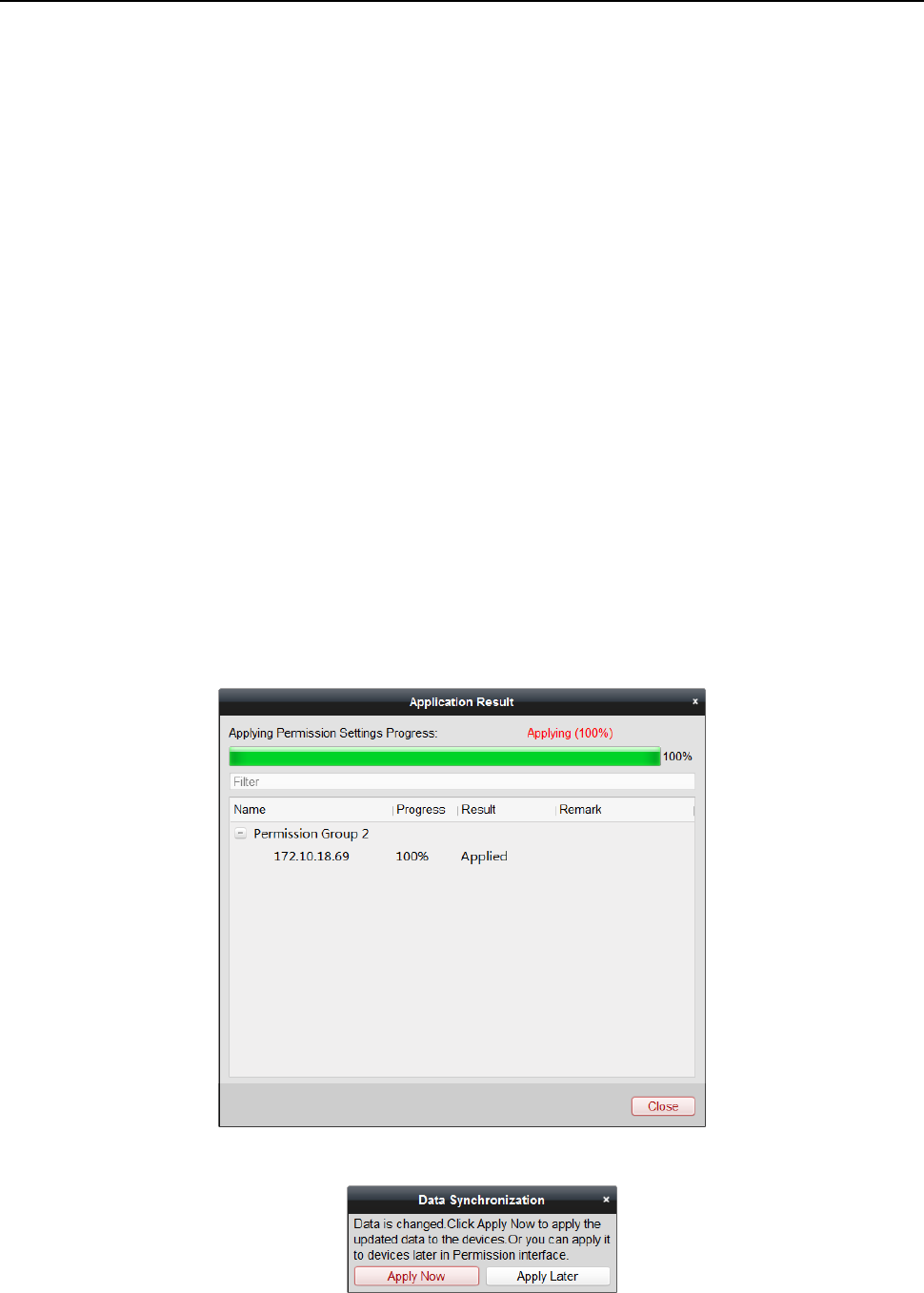
Face Recognition Terminal User Manual
94
(Optional) You can select the door or door station in the selected list and click < to cancel the
selection.
6. Click OK button to complete the permission adding. The selected person will have the
permission to enter/exit the selected door/door station with their linked card(s) or fingerprints.
7. (Optional) after adding the permission, you can click Details to modify it. Or you can select the
permission and click Modify to modify.
You can select the added permission in the list and click Delete to delete it.
6.7.2 Applying Permission
Purpose:
After configuring the permissions, you should apply the added permission to the access control
device to take effect.
Steps:
1. Select the permission(s) to apply to the access control device.
To select multiple permissions, you can hold the Ctrl or Shift key and select permissions.
2. Click Apply All to start applying all the selected permission(s) to the access control device or
door station.
You can also click Apply Changes to apply the changed part of the selected permission(s) to the
device(s).
3. The following window will pop up, indicating the applying permission result.
Notes:
When the permission settings are changed, the following hint box will pop up.
You can click Apply Now to apply the changed permissions to the device.
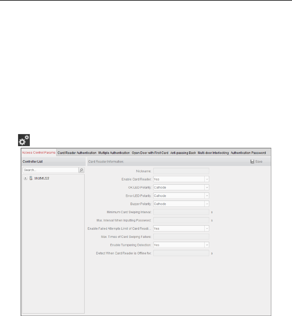
Face Recognition Terminal User Manual
95
Or you can click Apply Later to apply the changes later in the Permission interface.
The permission changes include changes of schedule and template, permission settings,
person’s permission settings, and related person settings (including card No., fingerprint, face
picture, linkage between card No. and fingerprint, linkage between card No. and fingerprint,
card password, card effective period, etc).
6.8 Advanced Functions
Purpose:
After configuring the person, template, and access control permission, you can configure the
advanced functions of access control application, such as access control parameters,
authentication password, and opening door with first card, anti-passing back, etc.
Note: The advanced functions should be supported by the device.
Click icon to enter the following interface.
6.8.1 Access Control Parameters
Purpose:
After adding the access control device, you can configure its access control point (door)’s
parameters, and its card readers’ parameters.
Click Access Control Parameters tab to enter the parameters settings interface.
Door Parameters
Steps:
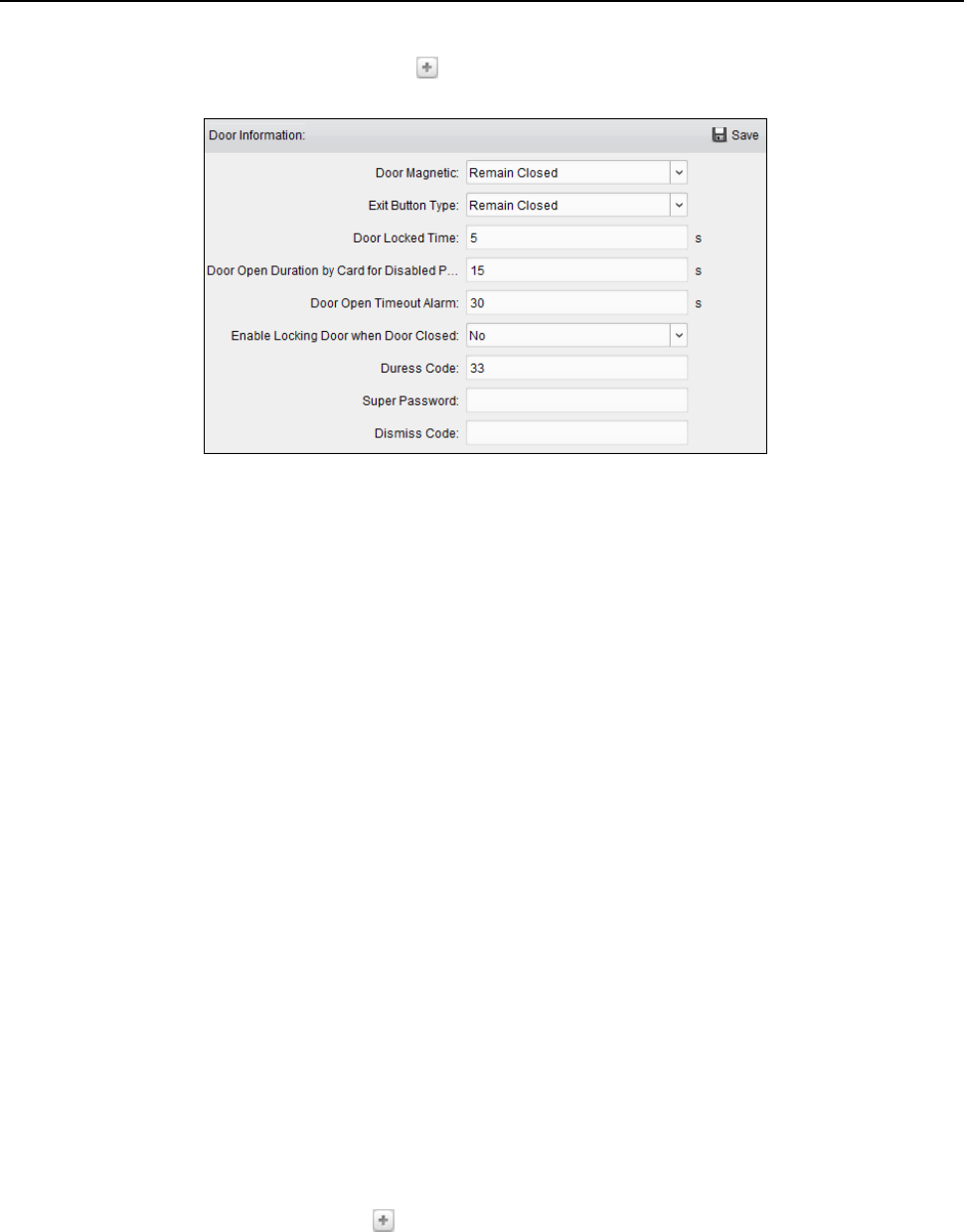
Face Recognition Terminal User Manual
96
1. In the controller list on the left, click to expand the access control device, select the door
(access control point) and you can edit the information of the selected door on the right.
2. You can editing the following parameters:
Door Magnetic: The Door Magnetic is in the status of Remain Closed (excluding special
conditions).
Exit Button Type: The Exit Button Type is in the status of Remain Open (excluding special
conditions).
Door Locked Time: After swiping the normal card and relay action, the timer for locking
the door starts working.
Door Open Duration by Card for Disabled Person: The door magnetic can be enabled with
appropriate delay after disabled person swipes the card.
Door Open Timeout Alarm: The alarm can be triggered if the door has not been closed.
Enable Locking Door when Door Closed: The door can be locked once it is closed even if
the Door Locked Time is not reached.
Duress Code: The door can open by inputting the duress code when there is duress. At the
same time, the client can report the duress event.
Super Password: The specific person can open the door by inputting the super password.
Dismiss Code: Input the dismiss code to stop the buzzer of the card reader.
Notes:
The duress code, Super password, and dismiss code should be different.
The duress code, super password, and the dismiss code should be different from the
authentication password.
The duress code, super password, and the dismiss code should contain 4 to 8 numerics.
3. Click Save button to save parameters.
Card Reader Parameters
Steps:
1. In the device list on the left, click to expand the door, select the card reader name and you
can edit the card reader parameters on the right.
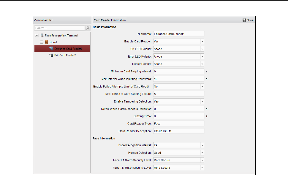
Face Recognition Terminal User Manual
97
2. You can edit the following parameters:
Nickname: Edit the card reader name as desired.
Enable Card Reader: Select Yes to enable the card reader.
OK LED Polarity: Select the OK LED Polarity of the card reader mainboard.
Error LED Polarity: Select the Error LED Polarity of the card reader mainboard.
Buzzer Polarity: Select the Buzzer LED Polarity of the card reader mainboard.
Minimum Card Swiping Interval: If the interval between card swiping of the same card is
less than the set value, the card swiping is invalid. You can set it as 0 to 255.
Max. Interval When Inputting Password: When you inputting the password on the card
reader, if the interval between pressing two digits is larger than the set value, the digits
you pressed before will be cleared automatically.
Enable Failed Attempts Limit of Card Reading: Enable to report alarm when the card
reading attempts reach the set value.
Max. Times of Card Swiping Failure: Set the max. failure attempts of reading card.
Enable Tampering Detection: Enable the anti-tamper detection for the card reader.
Detect When Card Reader is Offline for: When the access control device cannot connect
with the card reader for longer than the set time, the card reader will turn offline
automatically.
Buzzing Time: Set the card reader buzzing time. The available time ranges from 0 to 5999s.
0 represents continuous buzzing.
Card Reader Type: Get the card reader’s type.
Card Reader Description: Get the card reader description.
Face Recognition Interval: The time interval between two continuous face recognitions
when authenticating. By default, it is 2s.
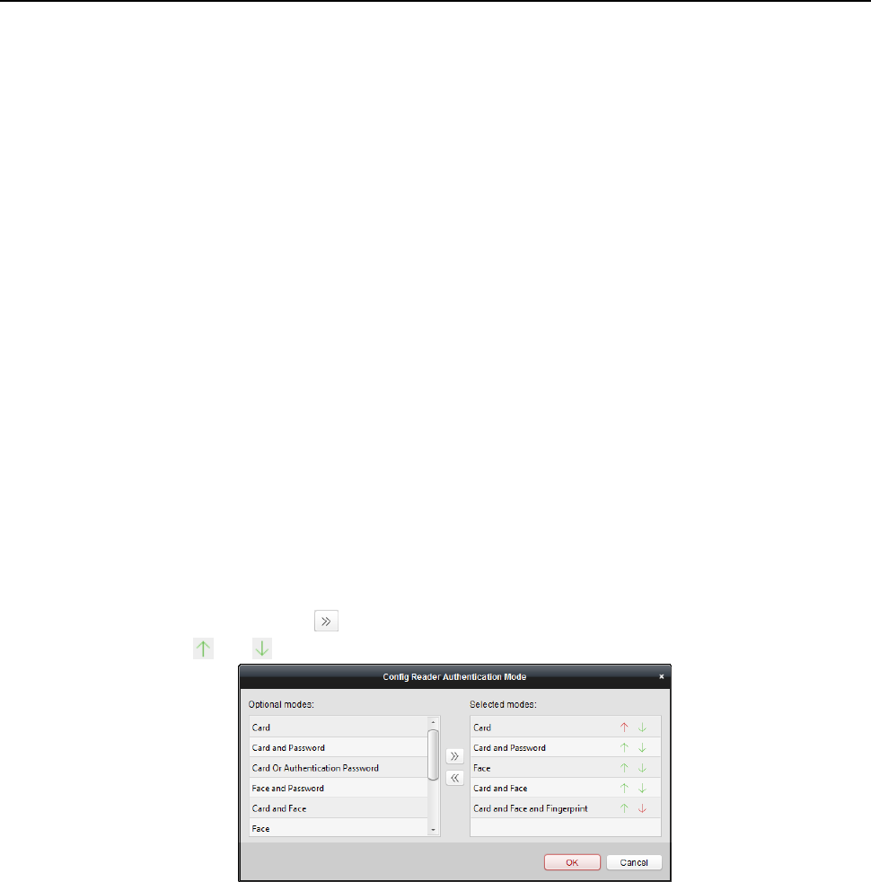
Face Recognition Terminal User Manual
98
Live Face Detection: Enable or disable the live face detection function. If enabling the
function, the device can recognize whether the person is a live one or not.
1:1 Security Level: Set the matching security level when authenticating via 1:1 matching
mode.
1:N Security Level: Set the matching security leveld when authenticating via 1:N matching
mode.
6.8.2 Card Reader Authentication
Purpose:
You can set the passing rules for the card reader of the access control device.
Steps:
1. Click Card Reader Authentication tab and select a card reader on the left.
2. Click Configuration button to select the card reader authentication modes for setting the
schedule.
Notes:
The available authentication modes depend on the device type.
Password refers to the card password set when issuing the card to the person in Chapter
6.5 Person Management.
1) Select the modes and click to add to the selected modes list.
You can click or to adjust the display order.
2) Click OK to confirm the selection.
3. After selecting the modes, the selected modes will display as icons.
Click the icon to select a card reader authentication mode.
4. Click and drag your mouse on a day to draw a color bar on the schedule, which means in that
period of time, the card reader authentication is valid.
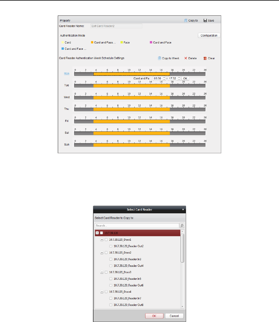
Face Recognition Terminal User Manual
99
5. Repeat the above step to set other time periods.
Or you can select a configured day and click Copy to Week button to copy the same settings to
the whole week.
(Optional) You can click Delete button to delete the selected time period or click Clear button
to delete all the configured time periods.
6. (Optional) Click Copy to button to copy the settings to other card readers.
7. Click Save button to save parameters.
6.8.3 Multiple Authentication
Purpose:
You can manage the cards by group and set the authentication for multiple cards for one access
control point (door).
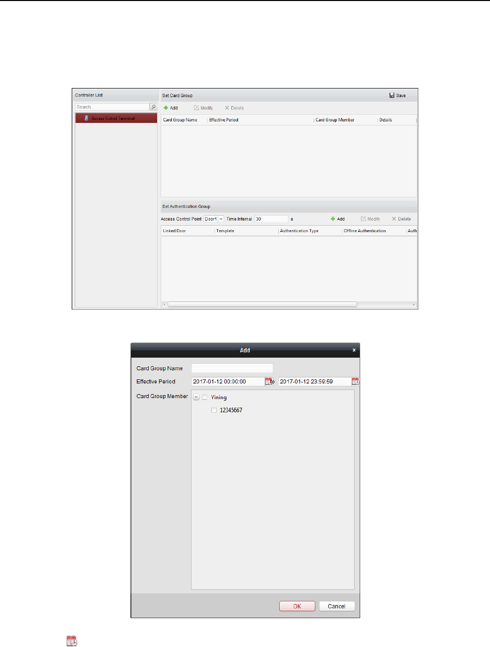
Face Recognition Terminal User Manual
100
Note: Please set the card permission and apply the permission setting to the access control device
first. For details, refer to Chapter 6.7 Permission Configuration.
Steps:
1. Click Multiple Authentication tab to enter the following interface.
2. Select access control device from the list on the left.
3. In the Set Card Group panel on the right, click Add button to pop up the following dialog:
1) In the Card Group Name field, input the name for the group as desired.
2) Click to set the effective time and expiry time of the card group.
3) Check the checkbox(es) to select the card(s) to add the card group.
4) Click OK to save the card group.
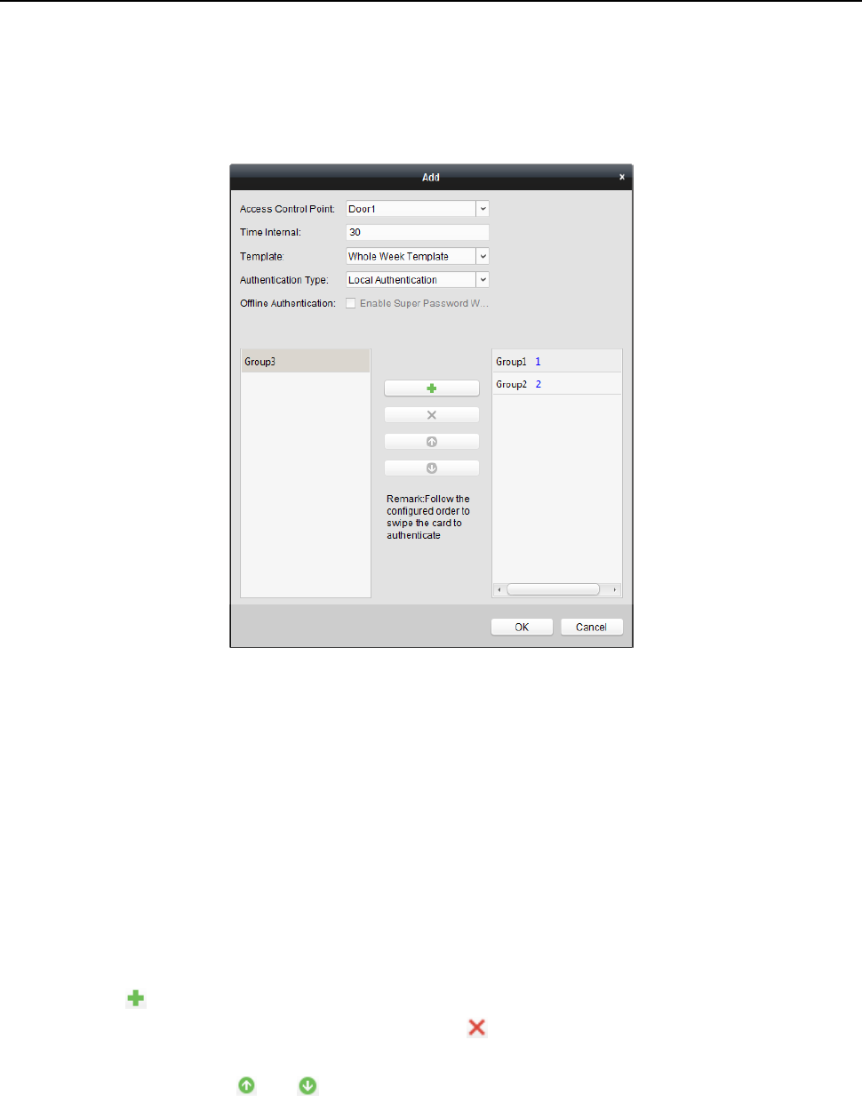
Face Recognition Terminal User Manual
101
4. In the Set Authentication Group panel, select the access control point (door) of the device for
multiple authentications.
5. Input the time interval for card swiping.
6. Click Add to pop up the following dialog.
1) Select the template of the authentication group from the dropdown list. For details about
setting the template, refer to Chapter 6.6 Schedule and Template.
2) Select the authentication type of the authentication group from the dropdown list.
Local Authentication: Authentication by the access control device.
Local Authentication and Remotely Open Door: Authentication by the access control
device and by the client.
For Local Authentication and Remotely Open Door type, you can check the checkbox
to enable the super password authentication when the access control device is
disconnected with the client.
Local Authentication and Super Password: Authentication by the access control
device and by the super password.
3) In the list on the left, the added card group will display. You can click the card group and
click to add the group to the authentication group.
You can click the added card group and click to remove it from the authentication
group.
You can also click or to set the card swiping order.
4) Input the Card Swiping Times for the selected card group.
Notes:
The Card Swiping Times should be larger than 0 and smaller than the added card
quantity in the card group.

Face Recognition Terminal User Manual
102
The upper limit of Card Swiping Times is 16.
5) Click OK to save the settings.
7. Click Save to save and take effect of the new settings.
Notes:
For each access control point (door), up to 20 authentication groups can be added.
For the authentication group which certificate type is Local Authentication, up to 8 card
groups can be added to the authentication group.
For the authentication group which certificate type is Local Authentication and Super
Password or Local Authentication and Remotely Open Door, up to 7 card groups can be
added to the authentication group.
6.8.4 Open Door with First Card
Purpose:
You can set multiple first cards for one access control point. After the first card swiping, it allows
multiple persons access the door or other authentication actions. The first card mode contains
Remain Open with First Card, Disable Remain Open with First Card, and First Card Authorization.
Remain Open with First Card: The door remains open for the configured time duration after
the first card swiping until the remain open duration ends.
Disable Remain Open with First Card: Disable the function.
First Card Authorization: All authentications (except for the authentications of super card,
super password, duress card, and duress code) are allowed only after the first card
authorization.
Notes:
The first card authorization is effective only on the current day. The authorization will be
expired after 24:00 on the current day.
You can swipe the first card again to disable the first card mode.
Steps:
1. Click Open Door with First Card tab to enter the following interface.
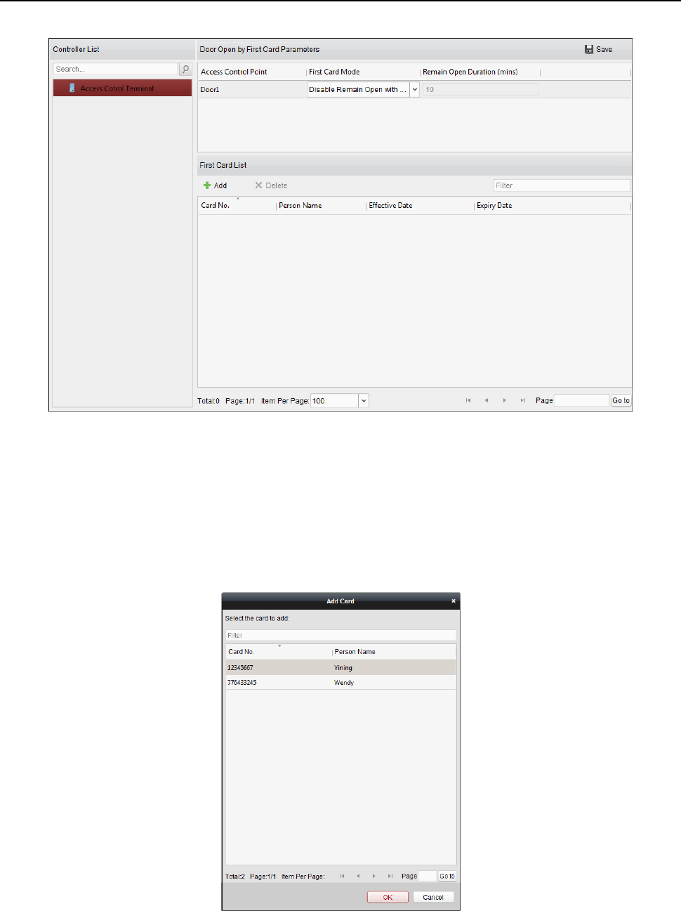
Face Recognition Terminal User Manual
103
2. Select an access control device from the list on the left.
3. Select the first card mode in the drop-down list for the access control point.
4. (Optional) If you select Remain Open with First Card, you should set remain open duration.
Notes:
The Remain Open Duration should be between 0 and 1440 minutes. By default, it is 10
minutes.
You can swipe the first card again to disable the first card mode.
5. In the First Card list, Click Add button to pop up the following dialog box.
1) Select the cards to add as first card for the door
Note: Set the card permission and apply the permission setting to the access control
device first. For details, refer to Chapter 6.7 Permission Configuration.
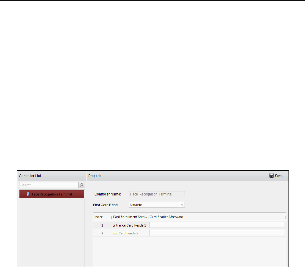
Face Recognition Terminal User Manual
104
2) Click OK button to save adding the card.
6. You can click Delete button to remove the card from the first card list.
7. Click Save to save and take effect of the new settings.
6.8.5 Anti-Passing Back
Purpose:
You can set to only pass the access control point according to the specified path and only one
person could pass the access control point after swiping the card.
Notes:
Either the anti-passing back or multi-door interlocking function can be configured for an access
control device at the same time.
You should enable the anti-passing back function on the access control device first.
Steps:
1. Click Anti-passing Back tab to enter the following interface.
2. Select an access control device from the device list on the left.
3. In the First Card Reader field, select the card reader as the beginning of the path.
4. In the list, click the text filed of Card Reader Afterward and select the linked card readers.
Example: If you select Reader In_01 as the beginning, and select Reader In_02, Reader Out_04
as the linked card readers. Then you can only get through the access control point by swiping
the card in the order as Reader In_01, Reader In_02 and Reader Out_04.
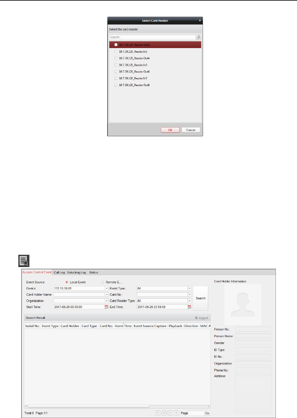
Face Recognition Terminal User Manual
105
Note: Up to four afterward card readers can be added for one card reader.
5. (Optional) You can enter the Select Card Reader dialog box again to edit its afterward card
readers.
6. Click Save to save and take effect of the new settings.
6.9 Searching Access Control Event
Purpose:
You can search the access control history events including remote event and local event via the
client.
Local Event: Search the access control event from the database of the control client.
Remote Event: Search the access control event from the device.
Click icon and click Access Control Event tab to enter the following interface.

Face Recognition Terminal User Manual
106
6.9.1 Searching Local Access Control Event
Steps:
1. Select the Event Source as Local Event.
2. Input the search condition according to actual needs.
3. Click Search. The results will be listed below.
4. For the access control event which is triggered by the card holder, you can click the event to
view the card holder details, including person No., person name, organization, phone number,
contact address and photo.
5. (Optional) If the event contains linked pictures, you can click in the Capture column to view the
captured picture of the triggered camera when the alarm is trigged.
6. (Optional) If the event contains linked video, you can click in the Playback column to view the
recorded video file of the triggered camera when the alarm is trigged.
Note: For setting the triggered camera, refer to Chapter 6.10.1 Access Control Event Linkage.
7. You can click Export to export the search result to the local PC in *.csv file.
6.9.2 Searching Remote Access Control Event
Steps:
1. Select the Event Source as Remote Event.
2. Input the search condition according to actual needs.
3. (Optional) You can check With Alarm Picture checkbox to search the events with alarm
pictures.
4. Click Search. The results will be listed below.
5. You can click Export to export the search result to the local PC in *.csv file.
6.10 Access Control Event Configuration
Purpose:
For the added access control device, you can configure its access control linkage including access
control event linkage, access control alarm input linkage, event card linkage, and cross-device
linkage.
Click the icon on the control panel,
or click Tool->Event Management to open the Event Management page.
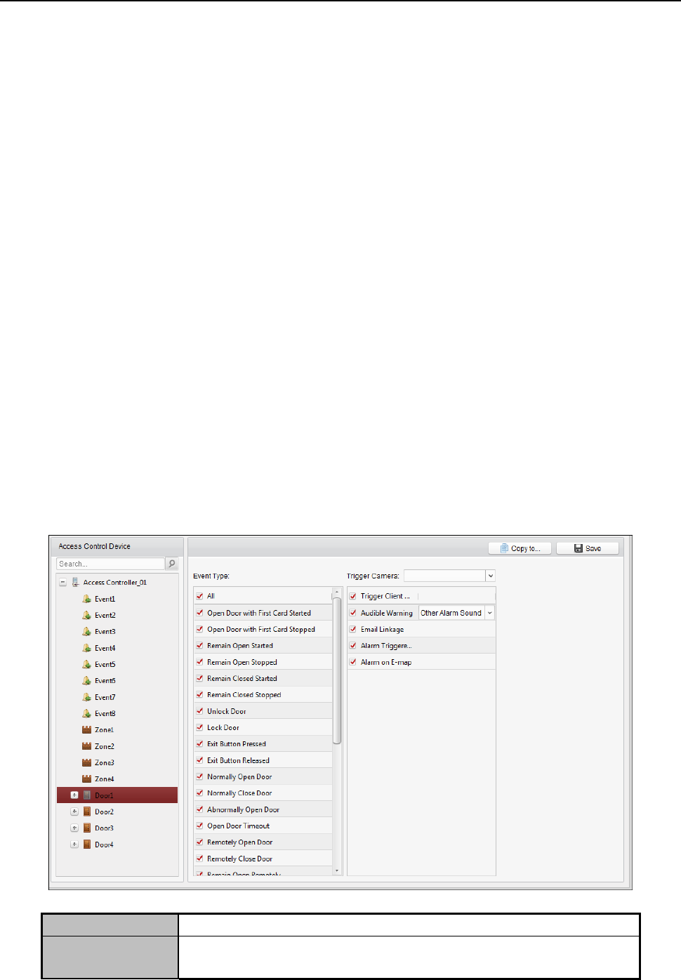
Face Recognition Terminal User Manual
107
6.10.1 Access Control Event Linkage
Purpose:
You can assign linkage actions to the access control event by setting up a rule. For example, when
the access control event is detected, an audible warning appears or other linkage actions happen.
Note: The linkage here refers to the linkage of the client software’s own actions.
Steps:
1. Click the Access Control Event tab.
2. The added access control devices will display in the Access Control Device panel on the left.
Select the access control device, or alarm input, or access control point (door), or card reader
to configure the event linkage.
3. Select the event type to set the linkage.
4. Select the triggered camera. The image or video from the triggered camera will pop up when
the selected event occurs.
To capture the picture of the triggered camera when the selected event occurs, you can also set
the capture schedule and the storage in Storage Schedule.
5. Check the checkboxes to activate the linkage actions. For details, refer to Table 14.1 Linkage
Actions for Access Control Event.
6. Click Save to save the settings.
7. You can click Copy to button to copy the access control event to other access control device,
alarm input, access control point, or card reader.
Select the parameters for copy, select the target to copy to, and click OK to confirm.
Table 1. 1 Linkage Actions for Access Control Event
Linkage Actions
Descriptions
Audible Warning
The client software gives an audible warning when alarm is
triggered. You can select the alarm sound for audible warning.
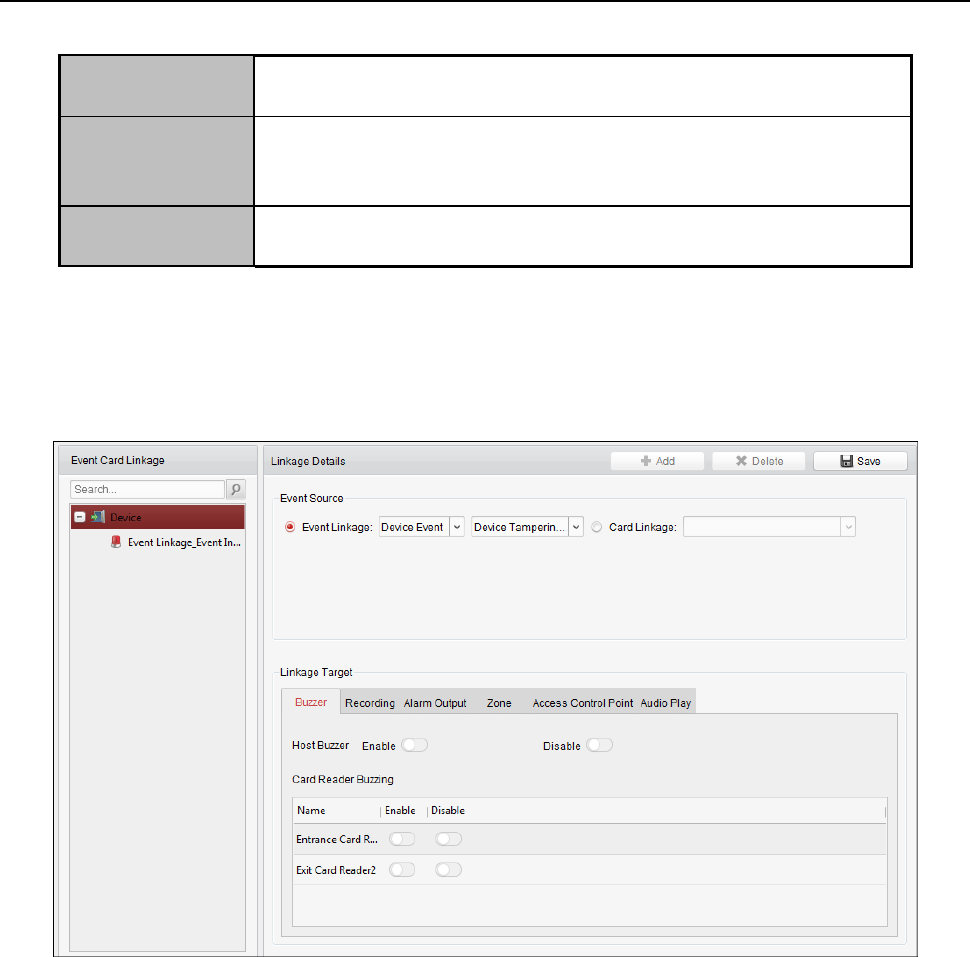
Face Recognition Terminal User Manual
108
Email Linkage
Send an email notification of the alarm information to one or
more receivers.
Alarm on E-map
Display the alarm information on the E-map.
Note: This linkage is only available to access control point and
alarm input.
Alarm Triggered
Pop-up Image
The image with alarm information pops up when alarm is
triggered.
6.10.2 Event Card Linkage
Click Event Card Linkage tab to enter the following interface.
Note: The Event Card Linkage should be supported by the device.
Select the access control device from the list on the left.
Click Add button to add a new linkage. You can select the event source as Event Linkage or Card
Linkage.
Event Linkage
For the event linkage, the alarm event can be divided into four types: device event, alarm input,
door event, and card reader event.
Steps:
1. Select a device on the left and click Add.
2. Click to select the linkage type as Event Linkage, and select the event type from the dropdown
list.
For Device Event, select the detailed event type from the dropdown list.
For Alarm Input, select the type as alarm or alarm recovery and select the alarm input
name from the panel.
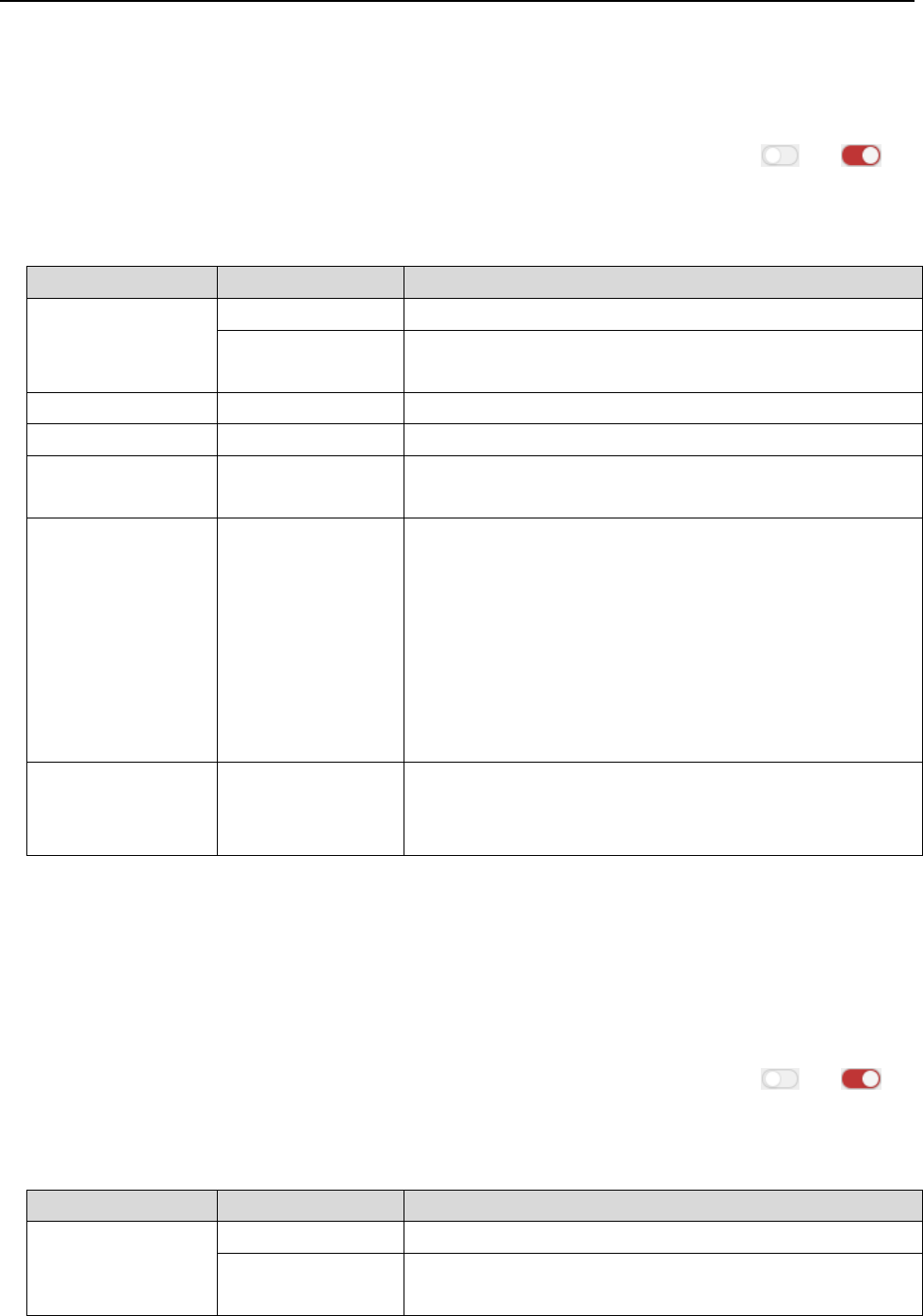
Face Recognition Terminal User Manual
109
For Door Event, select the detailed event type and select the source door from the panel.
For Card Reader Event, select the detailed event type and select the card reader from the
panel.
3. Click different tabs to set different parameters. Switch the property from to to
enable this function.
You can set the parameters of buzzer, recording, alarm output, zone, access control point, and
audio play.
Linkage Type
Linkage Target
Descriptions
Buzzer
Host Buzzer
The audible warning of controller will be triggered.
Card Reader
Buzzing
The audible warning of card reader will be triggered.
Recording
Capture Status
The real-time capture will be triggered.
Alarm Output
Alarm Output
The alarm output will be triggered for notification.
Zone
Zone
The zone will be armed or disarmed according to your
settings.
Access Control
Point
Access Control
Point
The door status of open, close, remain open, and
remain closed will be triggered.
Notes:
The door status of open, close, remain open, and
remain close cannot be triggered at the same
time.
The target door and the source door cannot be
the same one.
Audio Play
Audio Play Status
The audio prompt will be triggered. And the select
audio index related audio content will be played
according to the configured play mode.
4. Click Save to save and take effect of the parameters.
Card Linkage
Steps:
1. Click to select the linkage type as Card Linkage.
2. Input the card No. or select the card from the dropdown list.
3. Select the card reader from the panel for triggering.
5. Click different tabs to set different parameters. Switch the property from to to
enable this function.
You can set the parameters of buzzer, recording, alarm output, zone, access control point, and
audio play.
Linkage Type
Linkage Target
Descriptions
Buzzer
Host Buzzer
The audible warning of controller will be triggered.
Card Reader
Buzzing
The audible warning of card reader will be triggered.
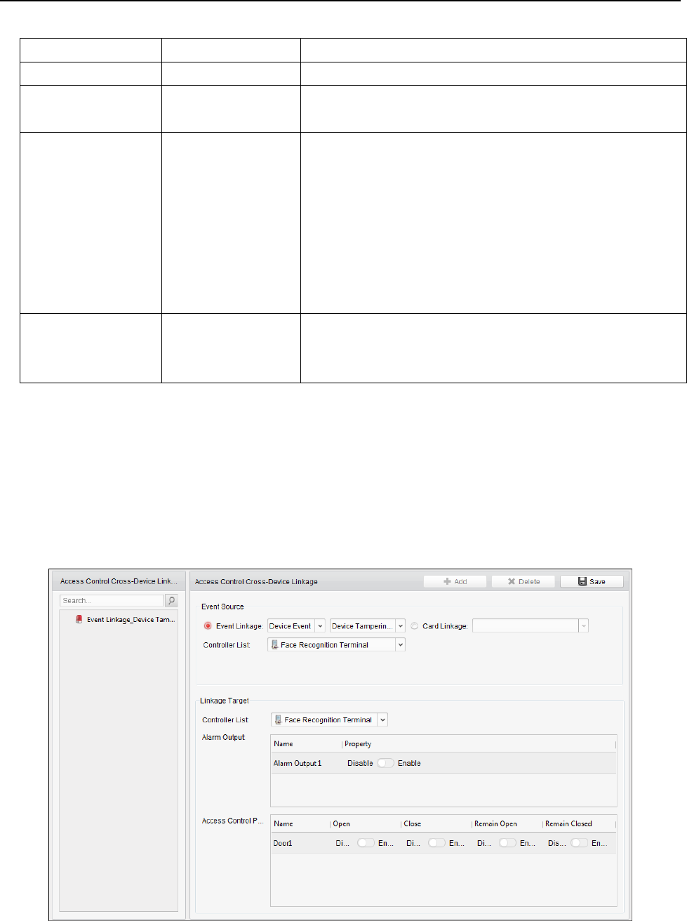
Face Recognition Terminal User Manual
110
Recording
Capture Status
The real-time capture will be triggered.
Alarm Output
Alarm Output
The alarm output will be triggered for notification.
Zone
Zone
The zone will be armed or disarmed according to your
settings.
Access Control
Point
Access Control
Point
The door status of open, close, remain open, and
remain closed will be triggered.
Notes:
The door status of open, close, remain open, and
remain close cannot be triggered at the same
time.
The target door and the source door cannot be
the same one.
Audio Play
Audio Play Status
The audio prompt will be triggered. And the select
audio index related audio content will be played
according to the configured play mode.
4. Click Save to save and take effect of the parameters.
6.10.3 Cross-Device Linkage
Purpose:
You can assign to trigger other access control device’s action by setting up a rule when the access
control event is triggered.
Click Cross-Device Linkage tab to enter the following interface.
Click Add button to add a new client linkage. You can select the event source as Event Linkage or
Card Linkage.

Face Recognition Terminal User Manual
111
Event Linkage
For the event linkage, the alarm event can be divided into four types: device event, alarm input,
door event, and card reader event.
Steps:
1. Click to select the linkage type as Event Linkage, select the access control device as event
source, and select the event type from the dropdown list.
For Device Event, select the detailed event type from the dropdown list.
For Alarm Input, select the type as alarm or alarm recovery and select the alarm input
name from the table.
For Door Event, select the detailed event type and select the door from the table.
For Card Reader Event, select the detailed event type and select the card reader from the
table.
2. Set the linkage target, select the access control device from the dropdown list as the linkage
target, and switch the property from to to enable this function.
Alarm Output: The alarm output will be triggered for notification.
Access Control Point: The door status of open, close, remain open, and remain close will
be triggered.
Note: The door status of open, close, remain open, and remain close cannot be triggered
at the same time.
3. Click Save button to save parameters.
Card Linkage
Steps:
1. Click to select the linkage type as Card Linkage.
2. Select the card from the dropdown list and select the access control device as event source.
3. Select the card reader from the table for triggering.
4. Set the linkage target, select the access control device from the dropdown list as the linkage
target, and switch the property from to to enable this function.
Alarm Output: The alarm output will be triggered for notification.
5. Click Save button to save parameters.
6.11 Door Status Management
Purpose:
The door status of the added access control device will be displayed in real time. You can check the
door status and the linked event(s) of the selected door. You can control the status of the door and
set the status duration of the doors as well.
6.11.1 Access Control Group Management
Purpose:
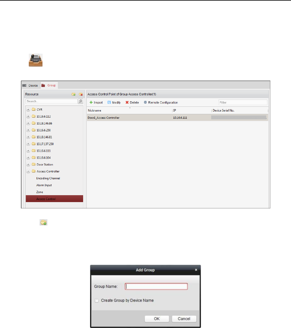
Face Recognition Terminal User Manual
112
Before controlling the door status and setting the status duration, you are required to organize it
into group for convenient management.
Perform the following steps to create the group for the access control device:
Steps:
1. Click on the control panel to open the Device Management page.
2. Click Group tab to enter the Group Management interface.
3. Perform the following steps to add the group.
1) Click to open the Add Group dialog box.
2) Input a group name as you want.
3) Click OK to add the new group to the group list.
You can also check the checkbox Create Group by Device Name to create the new group by
the name of the selected device.
4. Perform the following steps to import the access control points to the group:
1) Click Import on Group Management interface, and then click the Access Control tab to
open the Import Access Control page.
Notes:
You can also select Alarm Input tab and import the alarm inputs to group.
For the Video Access Control Terminal, you can add the cameras as encoding channel
to the group.
2) Select the names of the access control points in the list.
3) Select a group from the group list.
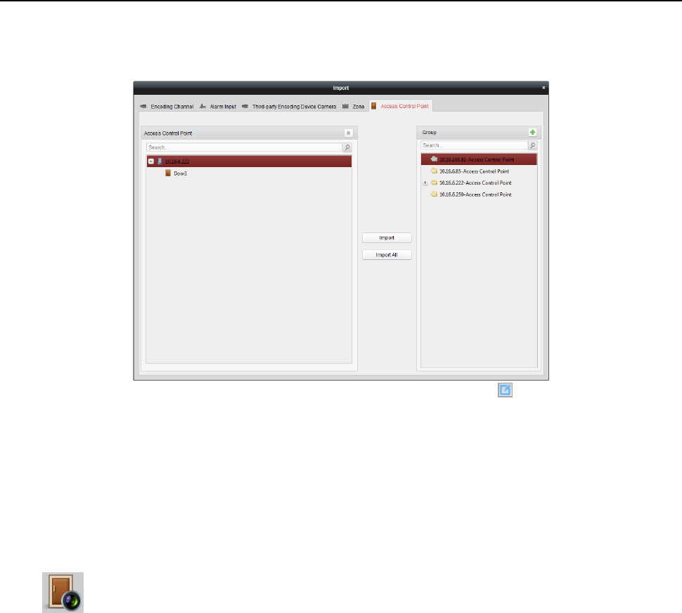
Face Recognition Terminal User Manual
113
4) Click Import to import the selected access control points to the group.
You can also click Import All to import all the access control points to a selected group.
5. After importing the access control points to the group, you can click , or double-click the
group/access control point name to modify it.
6.11.2 Anti-control the Access Control Point (Door)
Purpose:
You can control the status for a single access control point (a door), including opening door, closing
door, remaining open, and remaining closed.
Click icon on the control panel to enter the Status Monitor interface.
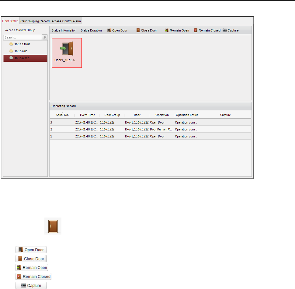
Face Recognition Terminal User Manual
114
Steps:
1. Select an access control group on the left. For managing the access control group, refer to
Chapter 6.11.1 Access Control Group Management.
2. The access control points of the selected access control group will be displayed on the right.
Click icon on the Status Information panel to select a door.
3. Click the following button listed on the Status Information panel to control the door.
: Click to open the door once.
: Click to close the door once.
: Click to keep the door open.
: Click to keep the door closed.
: Click to capture the picture manually.
4. You can view the anti-control operation result in the Operation Log panel.
Notes:
If you select the status as Remain Open/Remain Closed, the door will keep open/closed until a
new anti-control command being made.
The Capture button is available when the device supports capture function. And it cannot be
realized until the storage server is configured.
If the door is in remain closed status, only super card can open the door or open door via the
client software.
6.11.3 Status Duration Configuration
Purpose:
You can schedule weekly time periods for an access control point (door) to remain open or remain
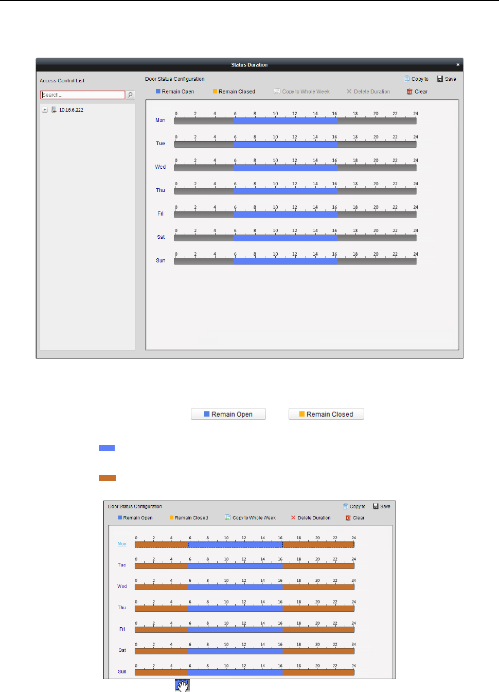
Face Recognition Terminal User Manual
115
closed.
In the Door Status module, click Status Duration button to enter the Status Duration interface.
Steps:
1. Click to select a door from the access control device list on the left.
2. On the Door Status Configuration panel on the right, draw a schedule for the selected door.
1) Select a door status brush as or .
Remain Open: The door will keep open during the configured time period. The brush is
marked as .
Remain Closed: The door will keep closed during the configured duration. The brush is
marked as .
2) Click and drag on the timeline to draw a color bar on the schedule to set the duration.
3) When the cursor turns to , you can move the selected time bar you just edited. You can
also edit the displayed time point to set the accurate time period.
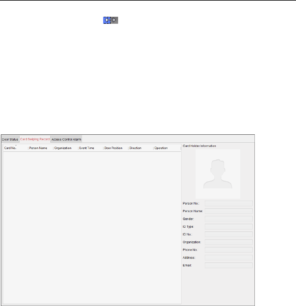
Face Recognition Terminal User Manual
116
When the cursor turns to , you can lengthen or shorten the selected time bar.
3. Optionally, you can select the schedule time bar and click Copy to Whole Week to copy the
time bar settings to the other days in the week.
4. You can select the time bar and click Delete Duration to delete the time period.
Or you can click Clear to clear all configured durations on the schedule.
5. Click Save to save the settings.
6. You can click Copy to button to copy the schedule to other doors.
6.11.4 Real-time Card Swiping Record
Click Card Swiping Record tab to enter the following interface.
The logs of card swiping records of all access control devices will display in real time. You can view the details of the
card swiping event, including card No., person name, organization, event time, etc.
You can also click the event to view the card holder details, including person No., person name, organization, phone,
contact address, etc.
6.11.5 Real-time Access Control Alarm
Purpose:
The logs of access control events will be displayed in real time, including device exception, door event, card reader
event, and alarm input.
Click Access Control Alarm tab to enter the following interface.
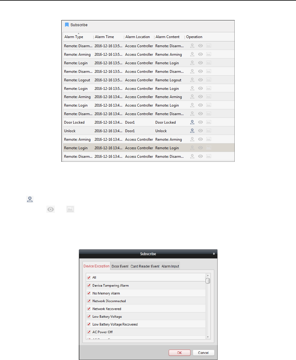
Face Recognition Terminal User Manual
117
Steps:
1. All access control alarms will display in the list in real time.
You can view the alarm type, alarm time, location, etc.
2. Click to view the alarm on E-map.
3. You can click or to view the live view or the captured picture of the triggered camera when the alarm is
trigged.
Note: For setting the triggered camera, refer to Chapter 6.10.1 Access Control Event Linkage.
4. Click Subscribe to select the alarm that the client can receive when the alarm is triggered.
1) Check the checkbox(es) to select the alarm(s), including device exception alarm, door event alarm, card
reader alarm, and alarm input.
2) Click OK to save the settings.
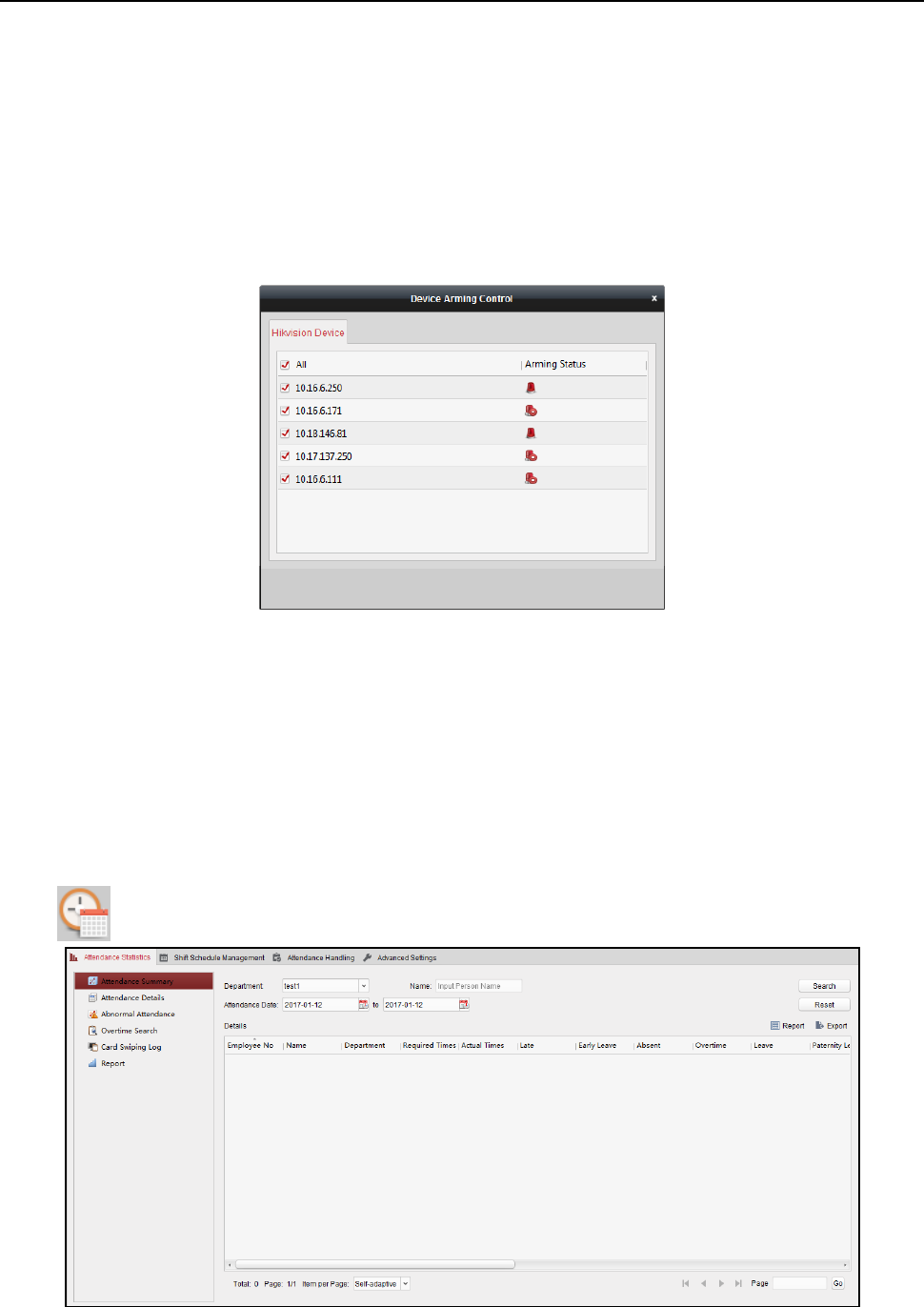
Face Recognition Terminal User Manual
118
6.12 Arming Control
Purpose:
You can arm or disarm the device. After arming the device , the client can receive the alarm information from the
device.
Steps:
1. Click Tool->Device Arming Control to pop up the Device Arming Control window.
2. Arm the device by checking the corresponding checkbox.
Then the alarm information will be auto uploaded to the client software when alarm occurs.
6.13 Time and Attendance
Purpose:
The Time and Attendance module provides multiple functionalities, including shift schedule
management, attendance handling, attendance statistics and other advanced functions.
Before you start:
You should add organization and person in Access Control module. For details, refer to Chapter
6.4.1 Adding Organization and Chapter 6.5.1 Adding Person.
Perform the following steps to access the Time and Attendance module.
Click to enter the Time and Attendance module as follows:
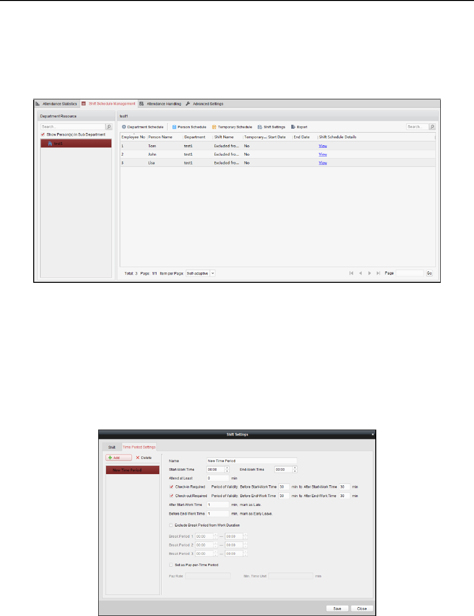
Face Recognition Terminal User Manual
119
6.13.1 Shift Schedule Management
Open Time and Attendance module and click Shift Schedule Management to enter the Shift
Schedule Management interface.
Shift Settings
Purpose:
You can add time period and shift for the shift schedule.
Click Shift Settings to pop up Shift Settings dialog.
Adding Time Period
Steps:
1. Click Time Period tab.
2. Click Add.
3. Set the related parameters.
Name: Set the name for time period.
Start-Work / End-Work Time: Set the start-work time and end-work time.
Attend at Least: Set the minimum attendance time.
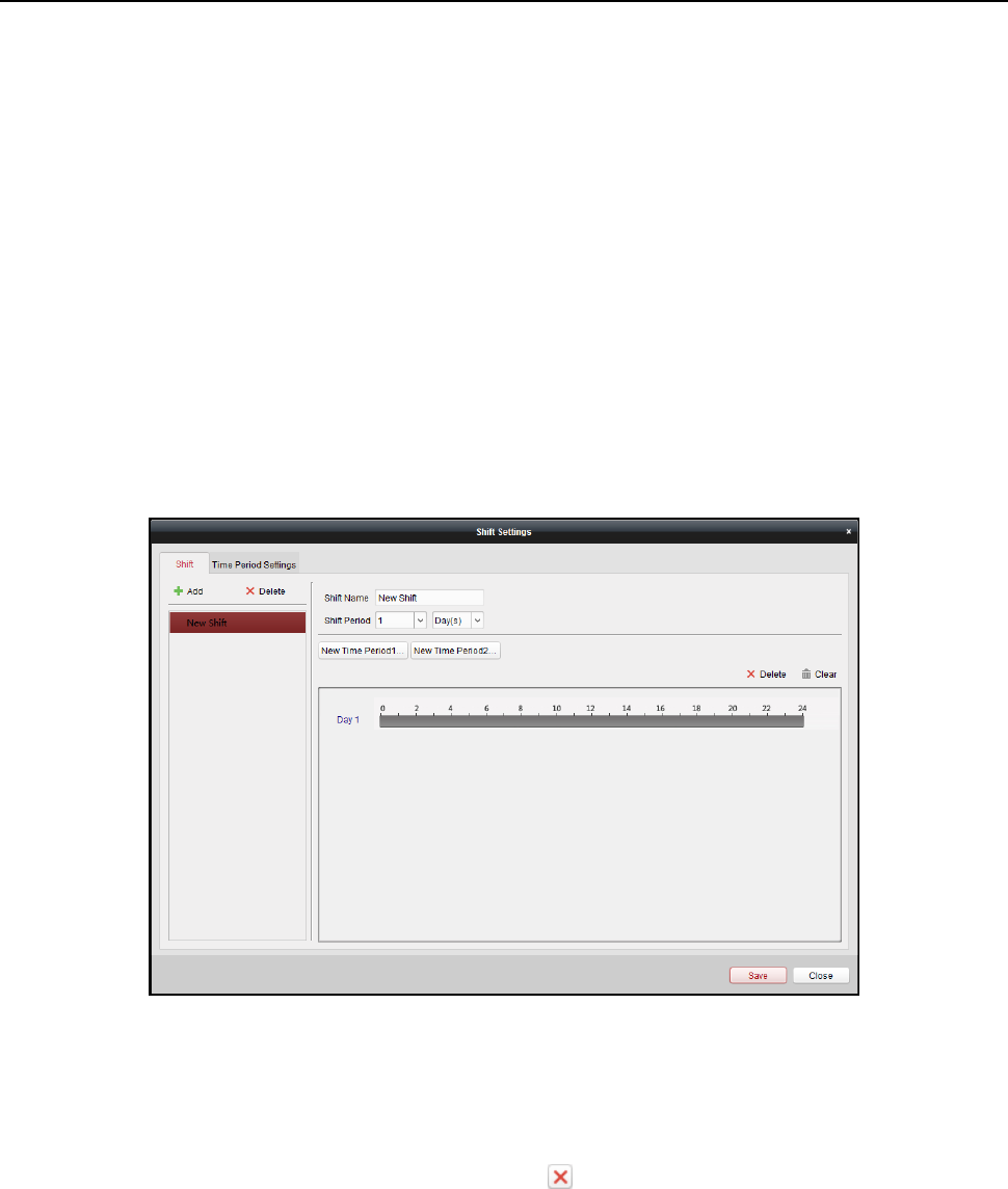
Face Recognition Terminal User Manual
120
Check-in / Check-out Required: Check the checkboxes and set the valid period for check-in or
check-out.
Mark as Late/Mark as Early Leave: Set the time period for late or early leave.
Exclude Break Period from Work Duration: Check the checkbox and set the break period
excluded.
Note: Up to 3 break periods can be set.
Set as Pay-per-Time Period: Check the checkbox and set the pay rate and minimum time unit.
4. Click Save to save the settings.
The added time period will display on the left panel of the dialog.
You can also click Delete to delete the time period.
Adding Shift
Steps:
1. Click Shift Tab.
2. Click Add.
3. Set the name for shift.
4. Select the shift period from the drop-down list.
5. Configure the shift period with the added time period.
1) Select the time period.
2) Click the time bar to apply the time period for the select day.
You can click the time period on the bar and click or Delete to delete the period.
You can also click Clear to delete all days’ time period.
6. Click Save to save the settings.
The added shift will display on the left panel of the dialog.
You can also click Delete on the left panel to delete the shift.
Shift Schedule Settings
Purpose:
After setting the shift, you can set department schedule, person schedule and temporary schedule.
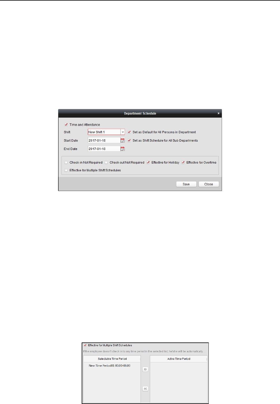
Face Recognition Terminal User Manual
121
Note: The temporary schedule has higher priority than department schedule and person schedule.
Department Schedule
You can set the shift schedule for one department, and all the persons in the department will be
assigned with the shift schedule.
Note: In Time and Attendance module, the department list is the same with the organization in
Access Control. For setting the organization in Access Control, refer to Chapter 6.4 Organization
Management.
Steps:
1. Open the Shift Schedule Management interface and select the department on the left panel.
2. Click Department Schedule to pop up Department Schedule dialog.
3. Check Time and Attendance checkbox.
All persons in the department expect those excluded from attendance will apply the
attendance schedule.
4. Select the shift from the drop-down list.
5. Set the start date and end date.
6. (Optional) Set other parameters for the schedule.
You can select Check-in Not Required, Check-out Not Required, Effective for Holiday, Effective
for Overtime, Effective for Multiple Shift Schedules.
Notes:
Multiple Shift Schedules contains more than one time periods. The person can check
in/out in any of the time periods and the attendance will be effective.
Example: If the multiple shift schedules contains three time periods: 00:00 to 07:00, 08:00
to 15:00 and 16:00 to 23:00. The attendance of the person adopting this multiple shift
schedules will be effective in any of the three time periods. If the person checks in at 07:50,
it will apply the nearest time period 08:00 to 15:00 to the person’s attendance.
After checking the Effective for Multiple Shift Schedules checkbox, you can select the
effective time period(s) from the added time periods for the persons in the department.
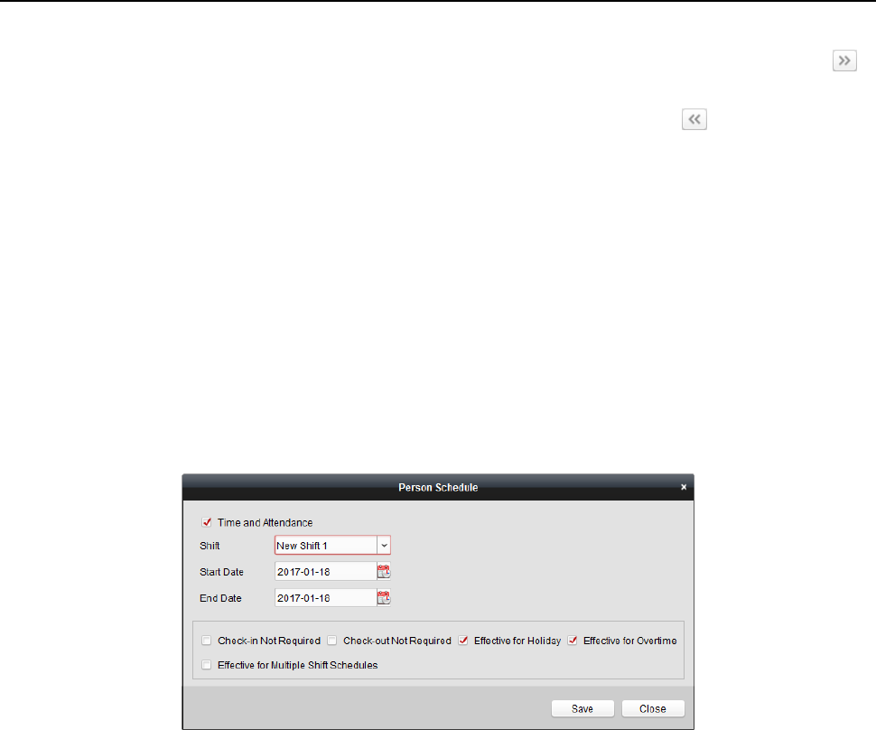
Face Recognition Terminal User Manual
122
1) In the Selectable Time Period list on the left, click the added time period and click
to add it to the right.
2) (Optional) To remove the selected time period, select it and click .
7. (Optional) Check Set as Default for All Persons in Department checkbox.
All persons in the department will use this shift schedule by default.
8. (Optional) If the selected department contains sub department(s), the Set as Shift Schedule for
All Sub Departments checkbox will display. You can check it to apply the department schedule
to its sub departments.
9. Click Save to save the settings.
Person Schedule
Steps:
1. Open the Shift Schedule Management interface and select the department on the left panel.
2. Select the person(s) on the right panel.
3. Click Person Schedule to pop up Person Schedule dialog.
4. Check Time and Attendance checkbox.
The configured person will apply the attendance schedule.
5. Select the shift from the drop-down list.
6. Set the start date and end date.
7. (Optional) Set other parameters for the schedule.
You can select Check-in Not Required, Check-out Not Required, Effective for Holiday, Effective
for Overtime, Effective for Multiple Shift Schedules.
8. Click Save to save the settings.
Temporary Schedule
Steps:
1. Open the Shift Schedule Management interface and select the department on the left panel.
2. Select the person(s) on the right panel.
3. Click Temporary Schedule to pop up Temporary Schedule dialog.
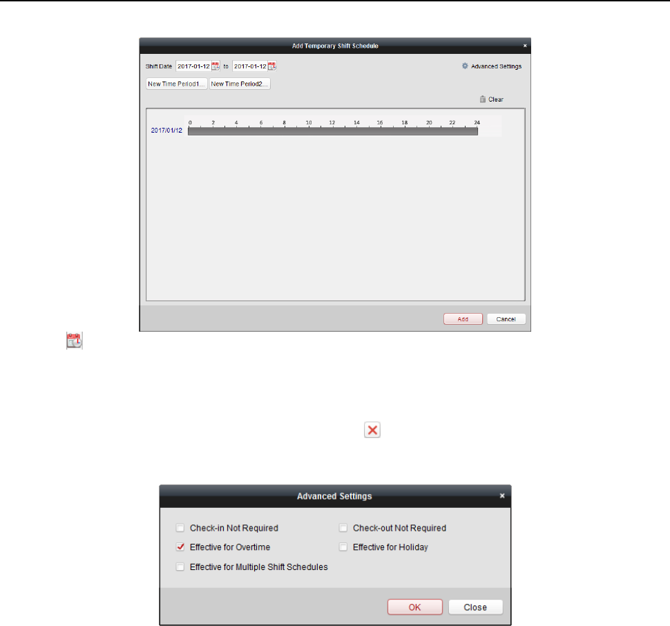
Face Recognition Terminal User Manual
123
4. Click to set the shift date.
5. Configure the shift date with the added time period.
1) Select the time period.
2) Click the time bar to apply the time period for the select date.
You can click the time period on the bar and click to delete the period.
You can also click Clear to delete all days’ time period.
6. You can click Advanced Settings to advanced attendance rules for the temporary schedule.
7. Click Add to save the settings.
Checking Shift Schedule Details
Steps:
1. On the Shift Schedule Management interface, select the department on the left panel.
2. Select the person(s) on the right panel.
3. Click View to pop up Shift Schedule Details dialog.
You can check the shift schedule details.
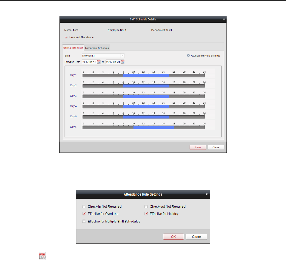
Face Recognition Terminal User Manual
124
4. Click Normal Schedule tab.
You can check and edit the normal schedule details.
1) Select the shift from the drop-down list.
2) Click Attendance Rule Settings to pop up Attendance Rule Settings dialog.
You can check the attendance rules as desired and click OK to save the settings.
3) Click to set the effective date.
4) Click Save to save the settings.
5. (Optional) Click Temporary Schedule tab.
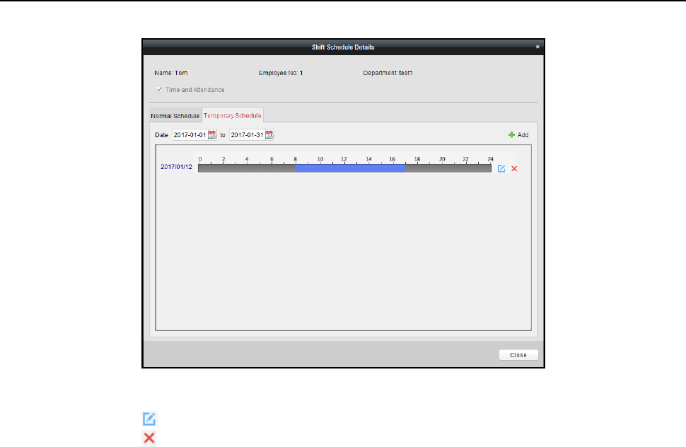
Face Recognition Terminal User Manual
125
You can check and edit the temporary schedule details.
(Optional) Click Add to add temporary schedule for the selected person.
(Optional) Click to edit the time period.
(Optional) Click to delete the temporary schedule.
Exporting Shift Schedule Details
On the Shift Schedule Management interface, select the department on the left panel and click
Export to export all persons’ shift schedule details to local PC.
Note: The exported details are saved in *.csv format.
6.13.2 Attendance Handling
Purpose:
You can handle the attendance, including check-in correction, check-out correction, leave and
business trip, and manual calculation of attendance.
Open Time and Attendance module and click Attendance Handling to enter the Attendance
Handling interface.
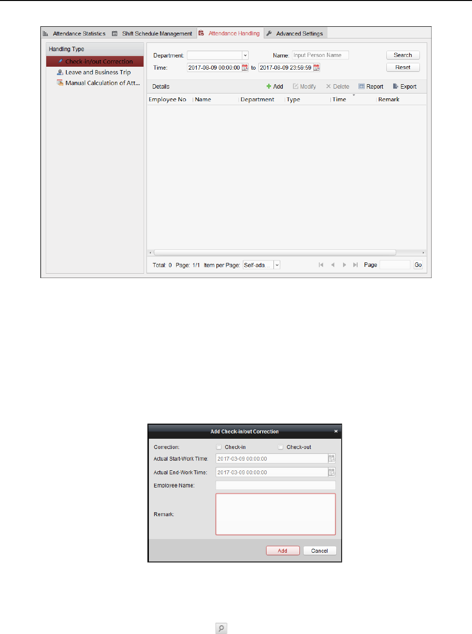
Face Recognition Terminal User Manual
126
Check-in/out Correction
Purpose:
You can add, edit, delete, search the check-in/out correction and generate the related report. You
can also export the check-in/out correction details to local PC.
Add Check-in/out Correction
Steps:
1. Click Check-in/out Correction tab.
2. Click Add to pop up Add Check-in/out Correction dialog.
3. Set the check-in/out correction parameters.
For Check-in Correction: Check Check-in checkbox and set the actual start-work time.
For Check-out Correction: Check Check-out checkbox and set the actual end-work time.
4. Click Employee Name field and select the person.
You can also input the keyword and click to search the person you want.
5. (Optional) Input the remark information as desired.
6. Click Add to add the check-in/out correction.
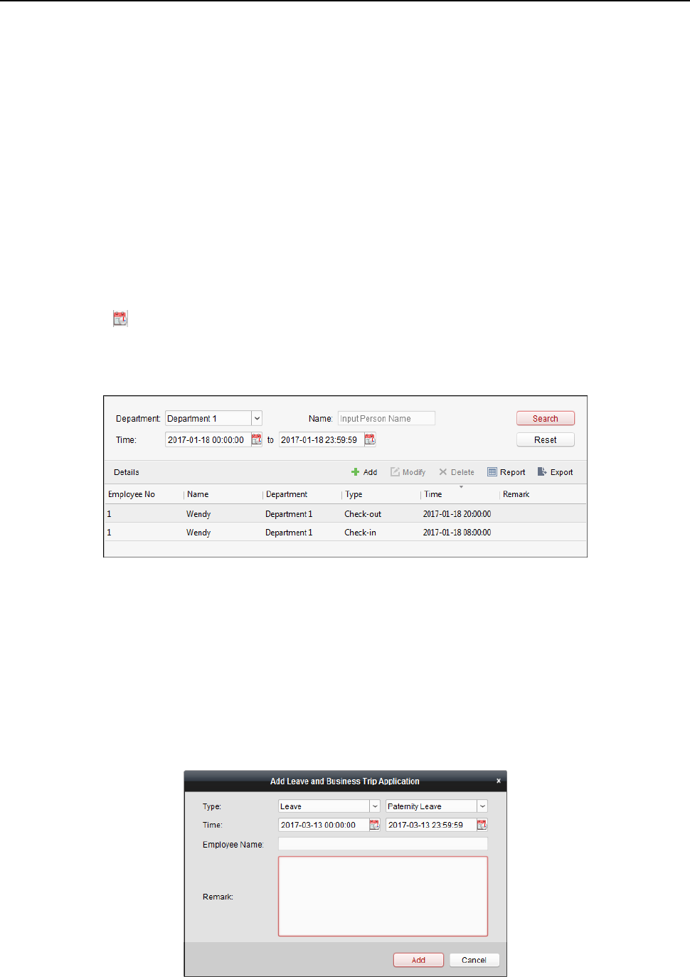
Face Recognition Terminal User Manual
127
The added check-in/out correction will display on the Attendance Handling interface.
(Optional) Select the check-in/out correction and click Modify to edit the correction.
(Optional) Select the check-in/out correction and click Delete to delete the correction.
(Optional) Click Report to generate the check-in/out correction report.
(Optional) Click Export to export the check-in/out correction details to local PC.
Note: The exported details are saved in *.csv format.
Search Check-in/out Correction
Steps:
1. Click Check-in/out Correction tab.
2. Set the searching conditions.
Department: Select the department from the drop-down list.
Name: Input the person name.
Time: Click to set the specified time as time range.
3. Click Search to search the check-in/out corrections.
The check-in/out correction details will display on the list.
You can also click Reset to reset the searching conditions.
Leave and Business Trip
Purpose:
You can add, edit, delete, search the leave and business trip and generate the related report. You
can also export the leave and business trip details to local PC.
Add Leave and Business Trip
Steps:
1. Click Leave and Business Trip tab.
2. Click Add to pop up Add Leave and Business Trip Application dialog.
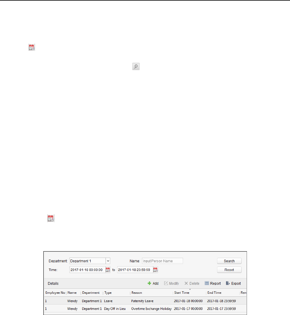
Face Recognition Terminal User Manual
128
3. Select the leave and business trip type from the Type drop-down list.
You can configure the leave type in Advanced Settings. For details, refer to Chapter 0 Leave
Type Settings.
4. Click to set the specified time as time range.
5. Click Employee Name field and select the person for this application.
You can also input the keyword and click to search the person you want.
6. (Optional) Input the remark information as desired.
7. Click Add to add the leave and business trip.
The added leave and business trip will display on the Attendance Handling interface.
(Optional) Select the leave and business trip and click Modify to edit the leave or business trip.
(Optional) Select the leave and business trip and click Delete to delete the leave or business
trip.
(Optional) Click Report to generate the leave or business trip report.
(Optional) Click Export to export the leave or business trip details to local PC.
Note: The exported details are saved in *.csv format.
Search Leave and Business Trip
Steps:
1. Click Leave and Business Trip tab.
2. Set the searching conditions.
Department: Select the department from the drop-down list.
Name: Input the person name.
Time: Click to set the specified time as time range.
3. Click Search to search the leave and business trips.
The leave and business trip details will display on the list.
You can also click Reset to reset the searching conditions.
Manual Calculation of Attendance
Purpose:
You can calculate the attendance result manually if needed by specifying the start time and end
time.
Steps:
1. Click Manual Calculation of Attendance tab.
2. Set the start time and end time for calculation.
3. Click Calculate to start.
Note: It can only calculate the attendance data within three months.
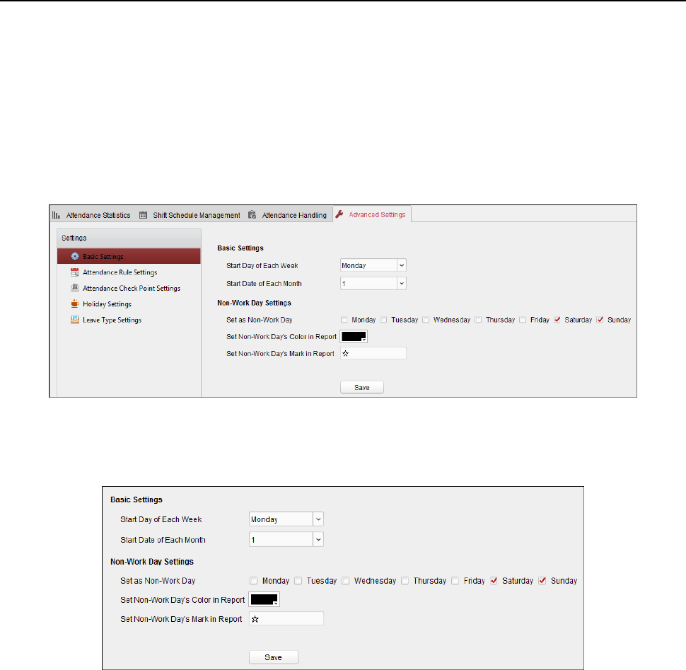
Face Recognition Terminal User Manual
129
6.13.3 Advanced Settings
Purpose:
You can configure the basic settings, attendance rule, attendance check point, holiday settings and
leave type for attendance.
Open Time and Attendance module and click Advanced Settings to enter the Advanced Settings
interface.
Basic Settings
Steps:
1. Click Basic Settings tab to enter the Basic Settings interface.
2. Set the basic settings.
Start Day of Each Week: You can select one day as the start day of each week.
Start Date of Each Month: You can select one day as the start date of each month.
3. Set the non-work day settings.
Set as Non-Work Day: Check the checkbox(es) to set the selected day(s) as non-work day.
Set Non-Work Day’s Color in Report: Click the color filed and select the color to mark the
non-work day in report.
Set Non-Work Day’s Mark in Report: Input the mark as non-work day in report.
4. Click Save to save the settings.
Attendance Rule Settings
Steps:
1. Click Attendance Rule Settings tab to enter the Attendance Rule Settings interface.
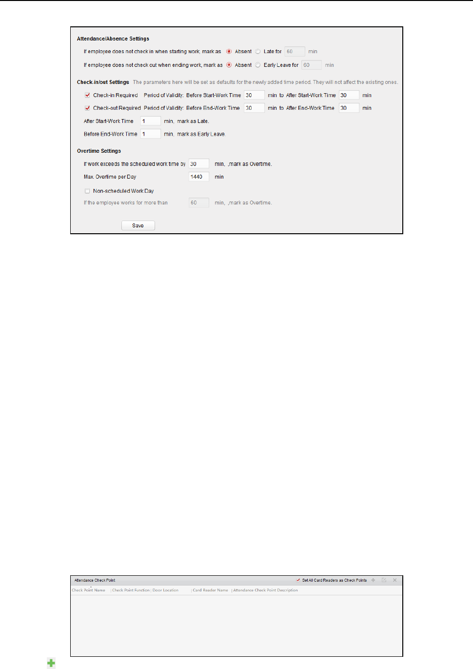
Face Recognition Terminal User Manual
130
2. Set the attendance or absence settings.
If employee does not check in when starting work, you can mark as Absent or Late and set the
late time.
If employee does not check out when ending work, you can mark as Absent or Early Leave and
set the early leave duration.
3. Set the Check-in/out Settings.
You can check the checkbox of Check-in Required or Check-out Required and set the valid
period.
You can also set the late rule or early leave rule.
Note: The parameters here will be set as default for the newly added time period. It will not
affect the existed one(s).
4. Set the overtime settings.
You can set the overtime rule and set the maximum overtime for each day.
(Optional) You can check Non-scheduled Work Day checkbox and set the overtime rule for
non-work day.
5. Click Save to save the settings.
Attendance Check Point Settings
You can set the card reader(s) of the access control point as the attendance check point, so that
the card swiping on the card reader(s) will be valid for attendance.
Steps:
1. Click Attendance Check Point Settings tab to enter the Attendance Check Point Settings
interface.
2. Click to pop up Add Attendance Check Point dialog.
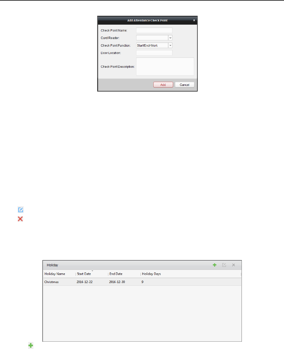
Face Recognition Terminal User Manual
131
3. Set the related information.
Check Point Name: Input a name for check point.
Card Reader: Select the card reader from the drop-down list.
Check Point Function: Select the function for check point.
Door Location: Input the door location.
Check Point Description: Set the description information for check point.
4. Click Add to add the attendance check point.
The added attendance check point will display on the list.
5. (Optional) Check Set All Card Readers as Check Points checkbox.
You can use all the card readers as check points.
Note: If this checkbox is unchecked, only the card readers in the list will be added as
attendance check points.
You can also edit or delete the card readers.
Click to edit the card reader.
Click to delete the card reader.
Holiday Settings
Steps:
1. Click Holiday Settings tab to enter the Holiday Settings interface.
2. Click to pop up Add Holiday dialog.
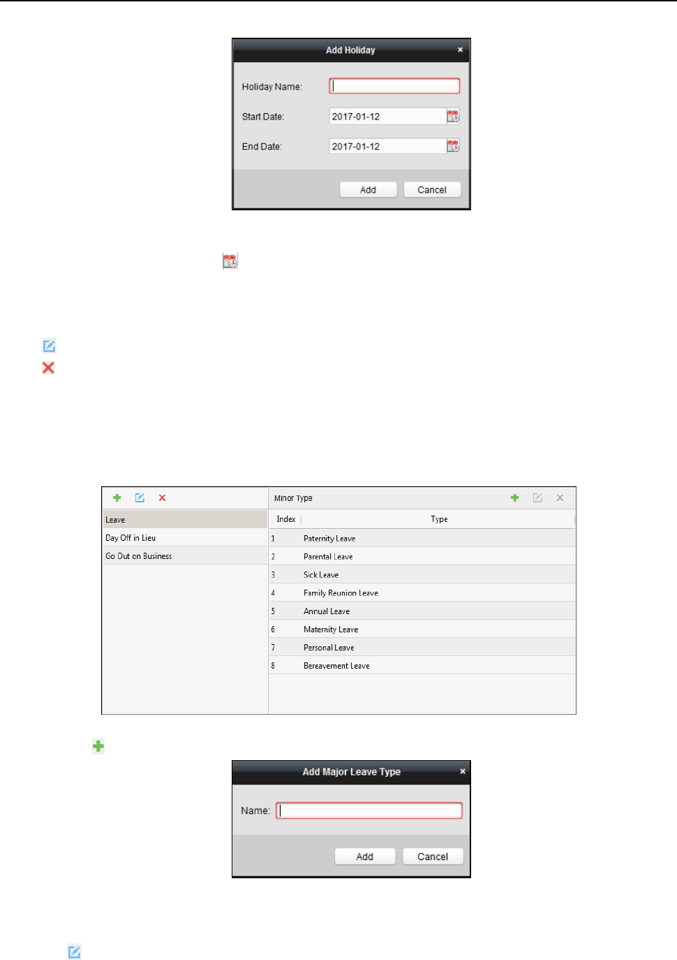
Face Recognition Terminal User Manual
132
3. Set the related parameters.
Holiday Name: Input the name for the holiday.
Start Date / End Date: Click to specify the holiday date.
4. Click Add to add the holiday.
The added holiday will display on the list.
You can also edit or delete the holiday.
Click to edit the holiday.
Click to delete the holiday.
Leave Type Settings
Purpose
Steps:
1. Click Leave Type Settings tab to enter the Leave Type Settings interface.
2. Add the major leave type.
1) Click on the left panel to pop up the Add Major Leave Type dialog.
2) Input the name for major leave type.
3) Click Add to add the major leave type.
You can also edit or delete the major leave type.
Click to edit the major leave type.
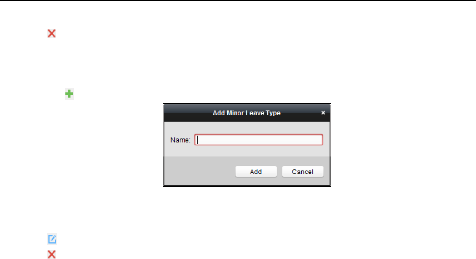
Face Recognition Terminal User Manual
133
Click to delete the major leave type.
3. Add the minor leave type.
1) Select the major leave type.
The minor leave type belonging to this major leave type will display on the right panel.
2) Click on the right panel to pop up the Add Minor Leave Type dialog.
3) Input the name for minor leave type.
4) Click Add to add the minor leave type.
You can also edit or delete the major leave type.
Click to edit the minor leave type.
Click to delete the minor leave type.
6.13.4 Attendance Statistics
Purpose:
After calculating attendance data, you can check the attendance summary, attendance details,
abnormal attendance, overtime, card swiping logs and reports based on the calculated attendance
data.
Notes:
The client automatically calculates the previous day’s attendance data at 1:00 am on the next
day.
Keep the client running at 1:00 am or it cannot calculate the previous day’s attendance data
automatically. If not calculated automatically, you can calculate the attendance data manually.
For details, refer to Manual Calculation of Attendance in Chapter 6.13.2 Attendance Handling.
Attendance Summary
Purpose:
You can get all the attendance information statistics of the employees in the specified time period.
Steps:
1. In the Time and Attendance module, click Attendance Statistics tab to enter the Attendance
Statistics page.
2. Click Attendance Summary item on the left panel to enter the Attendance Summary interface.
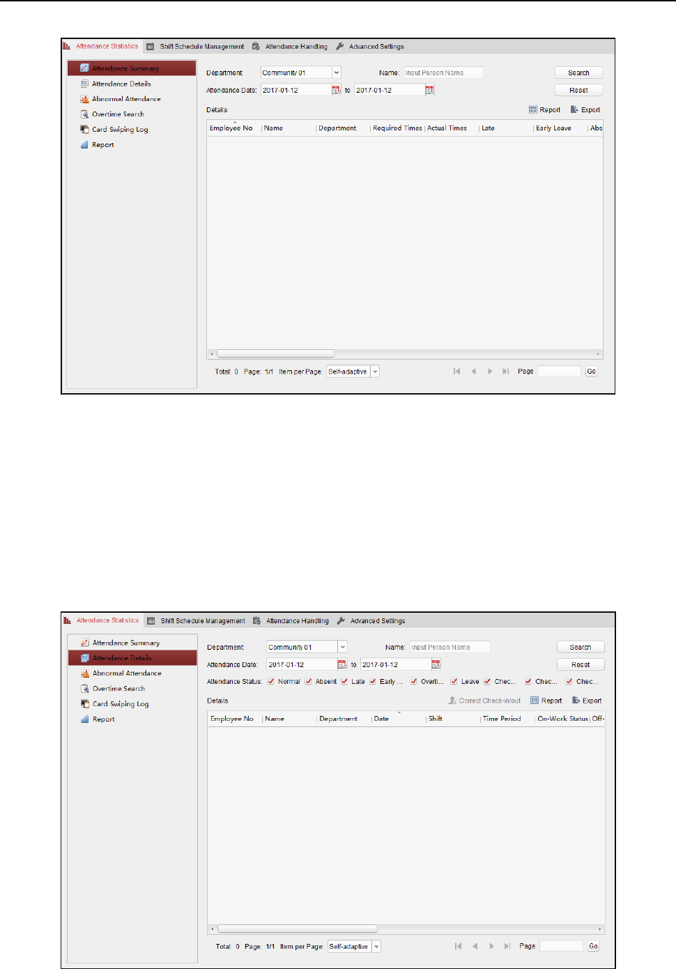
Face Recognition Terminal User Manual
134
3. Set the search conditions, including department, employee name and attendance date.
(Optional) You can click Reset to reset all the configured search conditions.
4. Click Search to start searching and the matched results will list on this page.
(Optional) Click Report to generate the attendance report.
(Optional) Click Export to export the results to the local PC.
Attendance Details
Steps:
1. In the Attendance Statistics page, click Attendance Details item on the left panel to enter the
Attendance Details interface.

Face Recognition Terminal User Manual
135
2. Set the search conditions, including department, employee name, attendance date and status.
(Optional) You can click Reset to reset all the configured search conditions.
3. Click Search to start searching and the matched results will list on this page.
(Optional) You can select a result item in the list and click Correct Check-in/out to correct the
check-in or check-out status.
(Optional) Click Report to generate the attendance report.
(Optional) Click Export to export the results to the local PC.
Abnormal Attendance
You can search and get the statistics of the abnormal attendance data, including No., name and
department of the employees, abnormal type, start/end time and date of attendance. For detailed
operations, refer to Chapter 0 Purpose:
After calculating attendance data, you can check the attendance summary, attendance details,
abnormal attendance, overtime, card swiping logs and reports based on the calculated attendance
data.
Notes:
The client automatically calculates the previous day’s attendance data at 1:00 am on the next
day.
Keep the client running at 1:00 am or it cannot calculate the previous day’s attendance data
automatically. If not calculated automatically, you can calculate the attendance data manually.
For details, refer to Manual Calculation of Attendance in Chapter 6.13.2 Attendance Handling.
Attendance Summary.
Overtime Search
You can search and get the overtime status statistics of the selected employee in the specified time
period. And you can check the detailed overtime information, including No., name and department
of the employees, attendance date, overtime duration and overtime type. For detailed operations,
refer to Chapter 0 Purpose:
After calculating attendance data, you can check the attendance summary, attendance details,
abnormal attendance, overtime, card swiping logs and reports based on the calculated attendance
data.
Notes:
The client automatically calculates the previous day’s attendance data at 1:00 am on the next
day.
Keep the client running at 1:00 am or it cannot calculate the previous day’s attendance data
automatically. If not calculated automatically, you can calculate the attendance data manually.
For details, refer to Manual Calculation of Attendance in Chapter 6.13.2 Attendance Handling.
Attendance Summary.
Card Swiping Log
You can search the card swiping logs used for the attendance statistics. After searching the logs,
you can check the card swiping details, including name and department of the employees, card
swiping time, card reader authentication mode and card No.. For detailed operations, refer to
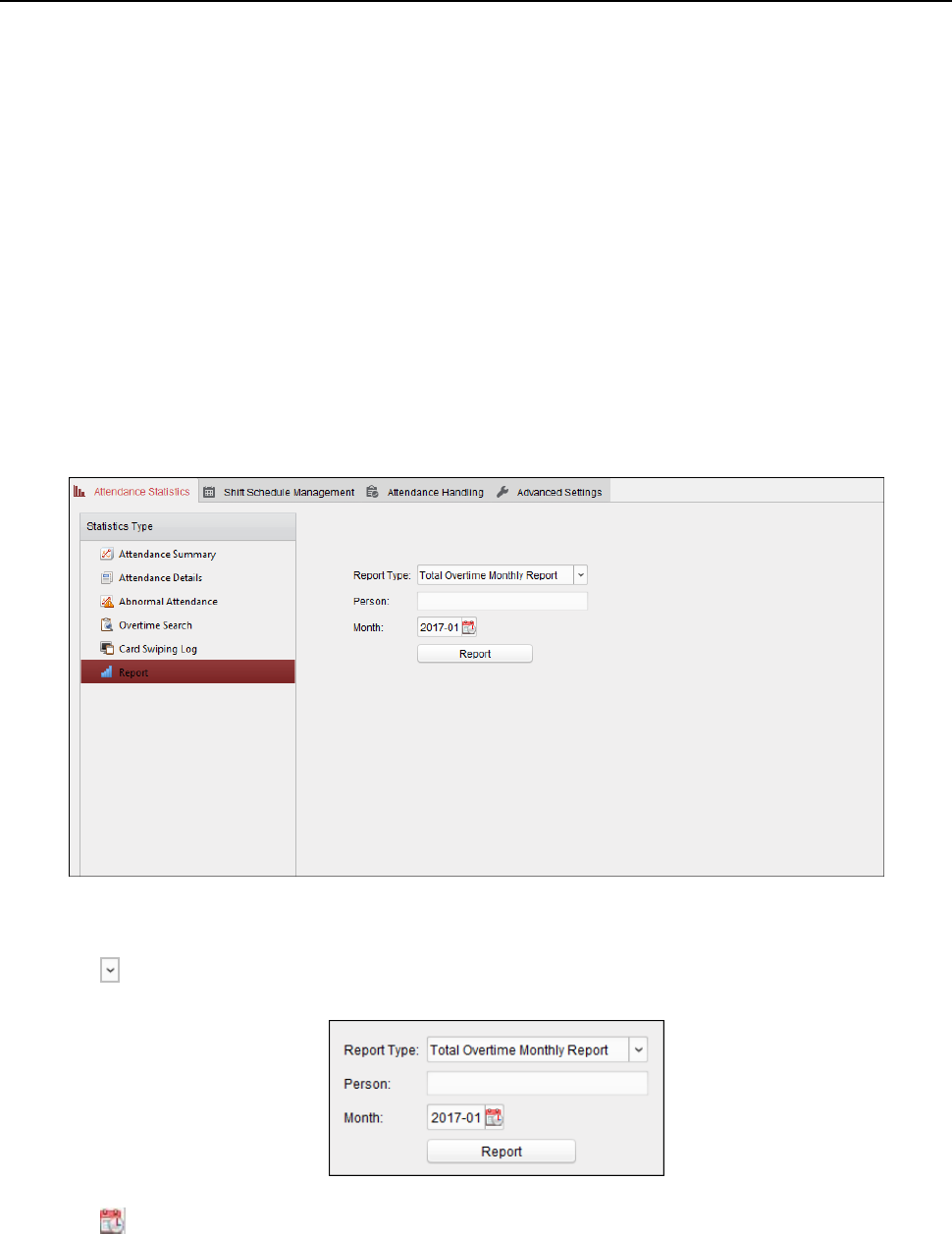
Face Recognition Terminal User Manual
136
Chapter 0 Purpose:
After calculating attendance data, you can check the attendance summary, attendance details,
abnormal attendance, overtime, card swiping logs and reports based on the calculated attendance
data.
Notes:
The client automatically calculates the previous day’s attendance data at 1:00 am on the next
day.
Keep the client running at 1:00 am or it cannot calculate the previous day’s attendance data
automatically. If not calculated automatically, you can calculate the attendance data manually.
For details, refer to Manual Calculation of Attendance in Chapter 6.13.2 Attendance Handling.
Attendance Summary.
Report
In the Attendance Statistics page, click Report item on the left panel to enter the Report interface.
Generating Total Overtime Monthly Report
Steps:
1. Click in the Report Type field to unfold the drop-down list and select Total Overtime
Monthly Report as the report type.
2. Click Person field to select the person.
3. Click to specify a month.
4. Click Report to start generating the matched total overtime monthly report.
Generating Overtime Details Monthly Report
Select Overtime Details Monthly Report as the report type. You can generate overtime details
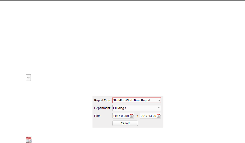
Face Recognition Terminal User Manual
137
monthly report. For detailed operations, refer to Generating Total Overtime Monthly Report.
Generating Attendance Monthly Report
Select Attendance Monthly Report as the report type. You can generate attendance monthly
report. For detailed operations, refer to Generating Total Overtime Monthly Report.
Generating Start/End-Work Time Report
Steps:
1. Click in the report type field to unfold the drop-down list and select Start/End-Work Time
Report as the report type.
2. Click Department field to select the department.
3. Click to specify the start date and end date of a date period.
4. Click Report to start generating the matched total overtime monthly report.
Generating Department Attendance Report
Set the report type as Department Attendance Report and you can generate department
attendance report. For detailed operations, refer to Generating Start/End-Work Time Report
above.
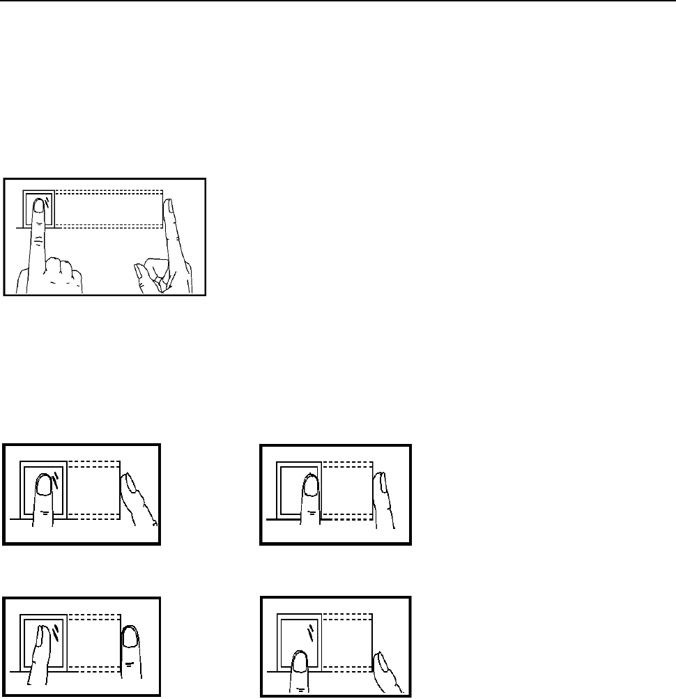
Face Recognition Terminal User Manual
138
Appendix A Tips for Scanning Fingerprint
Recommended Finger
Forefinger, middle finger or the third finger.
Correct Scanning
The figure displayed below is the correct way to scan your finger:
You should press your finger on the scanner horizontally. The center of your scanned finger should
align with the scanner center.
Incorrect Scanning
The figures of scanning fingerprint displayed below are wrong:
Environment
The scanner should avoid direct high light, high temperature, humid conditions and rain.
When it is dry, the scanner may not recognize your fingerprint successfully. You can blow your
finger and scan again after drying the finger.
Others
If your fingerprint is shallow, or it is hard to scan your fingerprint, we recommend you to use other
authentication methods.
If you have injuries on the scanned finger, the scanner may not recognize. You can change another
finger and try again.
Side
Edge II
Vertical
Edge I
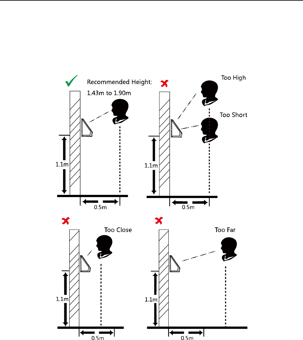
Face Recognition Terminal User Manual
139
Appendix B Tips When Collecting/Comparing Face
Picture
B.1 Positions (Recommended Distance:0.5m)
The position when collecting or comparing face picture is as below:
Note: For details about the relationship among person height, device height, and the distance
between the person and the device, see Appendix C.
B.2 Expression
Keep your expression naturally when collecting or comparing face pictures, just like the
expression in the picture below.
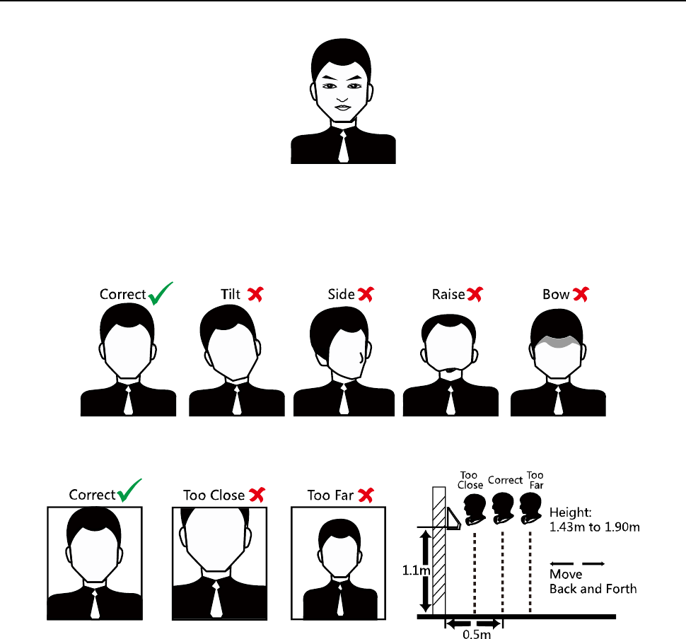
Face Recognition Terminal User Manual
140
Do not wear hat, sunglasses, or other accessories that can affect the facial recognition function.
Do not make your hair cover your eyes, ears, etc. and heavy makeup is not allowed.
B.3 Posture
In order to get a good quality and accurate face picture, position your face looking at the camera
when collecting or comparing face pictures.
B.4 Size
Make sure your face is in the middle of the collecting window.

Face Recognition Terminal User Manual
141
Appendix C Relationship between Device Height,
Person Height, and Standing Distance
0.3
0.5
0.8
Height Range
(Min~Max)
1
1.31~1.52
1.33~1.80
1.39~1.99
1.31~1.99
1.1 (Recommended)
1.41~1.62
1.43~1.90
1.49~2.09
1.41~2.09
1.2
1.51~1.72
1.52~2.11
1.56~2.20
1.51~2.20
Person
Height (m)
(m)
Device
Height
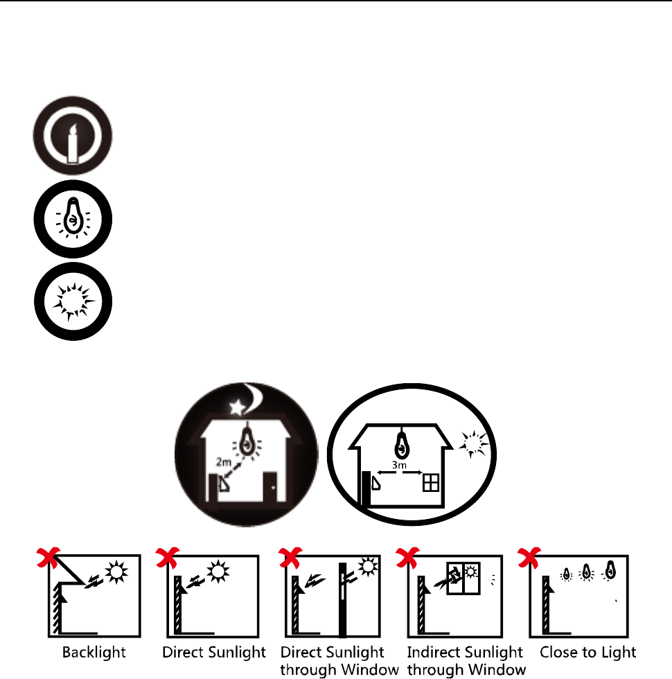
Face Recognition Terminal User Manual
142
Appendix D Tips for Installation Environment
1. Light Source Illumination Reference Value
Candel: 10Lux
Bulb: 100~850Lux
Sunlight: More than 1200Lux
2. Install the device indoors, at least 2 meters away from the light, and at least 3 meters away
from the window or door.
3. Avoid backlight, direct and indirect sunlight.
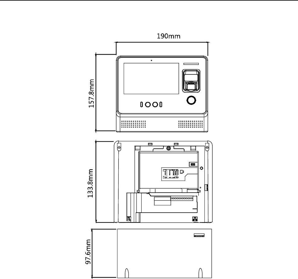
Face Recognition Terminal User Manual
143
Appendix E Dimension
0100001080123

Face Recognition Terminal User Manual
144
UD07930B