Hangzhou Hikvision Digital Technology KD81V Video Intercom Door Station User Manual Rev1
Hangzhou Hikvision Digital Technology Co., Ltd. Video Intercom Door Station Rev1
User Manual Rev1

UD.6L0206D1098A01
Video Intercom
Door Station (D Series)
User Manual
Video Intercom Door Station·User Manual
i
User Manual
© 2016 Hangzhou Hikvision Digital Technology Co., Ltd.
This user manual is intended for users of the models below:
Series
Model
Door Station (D Series)
DS-KD8102-V
It includes instructions on how to use the Product. The software embodied in the
Product is governed by the user license agreement covering that Product.
About this Manual
This Manual is subject to domestic and international copyright protection. Hangzhou
Hikvision Digital Technology Co., Ltd. (“Hikvision”) reserves all rights to this manual. This
manual cannot be reproduced, changed, translated, or distributed, partially or wholly,
by any means, without the prior written permission of Hikvision.
Trademarks
and other Hikvision marks are the property of Hikvision and are
registered trademarks or the subject of applications for the same by Hikvision and/or its
affiliates. Other trademarks mentioned in this manual are the properties of their
respective owners. No right of license is given to use such trademarks without express
permission.
Disclaimer
TO THE MAXIMUM EXTENT PERMITTED BY APPLICABLE LAW, HIKVISION MAKES NO WARRANTIES,
EXPRESS OR IMPLIED, INCLUDING WITHOUT LIMITATION THE IMPLIED WARRANTIES OF
MERCHANTABILITY AND FITNESS FOR A PARTICULAR PURPOSE, REGARDING THIS MANUAL.
HIKVISION DOES NOT WARRANT, GUARANTEE, OR MAKE ANY REPRESENTATIONS REGARDING THE
USE OF THE MANUAL, OR THE CORRECTNESS, ACCURACY, OR RELIABILITY OF INFORMATION
CONTAINED HEREIN. YOUR USE OF THIS MANUAL AND ANY RELIANCE ON THIS MANUAL SHALL BE
WHOLLY AT YOUR OWN RISK AND RESPONSIBILITY.
TO THE MAXIMUM EXTENT PERMITTED BY APPLICABLE LAW, IN NO EVENT WILL HIKVISION, ITS
DIRECTORS, OFFICERS, EMPLOYEES, OR AGENTS BE LIABLE TO YOU FOR ANY SPECIAL,
CONSEQUENTIAL, INCIDENTAL, OR INDIRECT DAMAGES, INCLUDING, AMONG OTHERS, DAMAGES
FOR LOSS OF BUSINESS PROFITS, BUSINESS INTERRUPTION, SECURITY BREACHES, OR LOSS OF DATA
OR DOCUMENTATION, IN CONNECTION WITH THE USE OF OR RELIANCE ON THIS MANUAL, EVEN IF
HIKVISION HAS BEEN ADVISED OF THE POSSIBILITY OF SUCH DAMAGES.
DS-KD8XXX-XYZ

Video Intercom Door Station·User Manual
ii
SOME JURISDICTIONS DO NOT ALLOW THE EXCLUSION OR LIMITATION OF LIABILITY OR CERTAIN
DAMAGES, SO SOME OR ALL OF THE ABOVE EXCLUSIONS OR LIMITATIONS MAY NOT APPLY TO YOU.
Support
Should you have any questions, please do not hesitate to contact your local dealer.
0103001060116
Video Intercom Door Station·User Manual
iii
Regulatory Information
FCC Information
Please take attention that changes or modification not expressly approved by the party
responsible for compliance could void the user’s authority to operate the equipment.
FCC compliance: This equipment has been tested and found to comply with the limits
for a Class B digital device, pursuant to part 15 of the FCC Rules. These limits are
designed to provide reasonable protection against harmful interference in a residential
installation. This equipment generates, uses and can radiate radio frequency energy and,
if not installed and used in accordance with the instructions, may cause harmful
interference to radio communications. However, there is no guarantee that interference
will not occur in a particular installation. If this equipment does cause harmful
interference to radio or television reception, which can be determined by turning the
equipment off and on, the user is encouraged to try to correct the interference by one
or more of the following measures:
—Reorient or relocate the receiving antenna.
—Increase the separation between the equipment and receiver.
—Connect the equipment into an outlet on a circuit different from that to which the
receiver is connected.
—Consult the dealer or an experienced radio/TV technician for help.
This equipment should be installed and operated with a minimum distance 20cm
between the radiator and your body.
FCC Conditions
This device complies with part 15 of the FCC Rules. Operation is subject to the following
two conditions:
1. This device may not cause harmful interference.
2. This device must accept any interference received, including interference that may
cause undesired operation.
EU Conformity Statement
This product and - if applicable - the supplied accessories too are
marked with "CE" and comply therefore with the applicable
harmonized European standards listed under the R&TTE Directive
1999/5/EC, the EMC Directive 2004/108/EC, the RoHS Directive
2011/65/EU.
2012/19/EU (WEEE directive): Products marked with this symbol
cannot be disposed of as unsorted municipal waste in the European
Union. For proper recycling, return this product to your local supplier
upon the purchase of equivalent new equipment, or dispose of it at
designated collection points. For more information see:
www.recyclethis.info
Video Intercom Door Station·User Manual
iv
2006/66/EC (battery directive): This product contains a battery that
cannot be disposed of as unsorted municipal waste in the European
Union. See the product documentation for specific battery information.
The battery is marked with this symbol, which may include lettering to
indicate cadmium (Cd), lead (Pb), or mercury (Hg). For proper recycling,
return the battery to your supplier or to a designated collection point.
For more information see: www.recyclethis.info
Industry Canada ICES-003 Compliance
This device meets the CAN ICES-3 (B)/NMB-3(B) standards requirements.
This device complies with Industry Canada licence-exempt RSS standard(s). Operation is
subject to the following two conditions:
(1) this device may not cause interference, and
(2) this device must accept any interference, including interference that may cause
undesired operation of the device.
Le présent appareil est conforme aux CNR d'Industrie Canada applicables aux appareils
radioexempts de licence. L'exploitation est autorisée aux deux conditions suivantes :
(1) l'appareil ne doit pas produire de brouillage, et
(2) l'utilisateur de l'appareil doit accepter tout brouillage radioélectrique subi, même si
le brouillage est susceptible d'en compromettre le fonctionnement.
Under Industry Canada regulations, this radio transmitter may only operate using an
antenna of a type and maximum (or lesser) gain approved for the transmitter by
Industry Canada. To reduce potential radio interference to other users, the antenna type
and its gain should be so chosen that the equivalent isotropically radiated power (e.i.r.p.)
is not more than that necessary for successful communication.
Conformément à la réglementation d'Industrie Canada, le présent émetteur radio peut
fonctionner avec une antenne d'un type et d'un gain maximal (ou inférieur) approuvé
pour l'émetteur par Industrie Canada. Dans le but de réduire les risques de brouillage
radioélectrique à l'intention des autres utilisateurs, il faut choisir le type d'antenne et
son gain de sorte que la puissance isotrope rayonnée équivalente (p.i.r.e.) ne dépasse
pas l'intensité nécessaire à l'établissement d'une communication satisfaisante.
This equipment should be installed and operated with a minimum distance 20cm between
the radiator and your body.
Cet équipement doit être installé et utilisé à une distance minimale de 20 cm entre le
radiateur et votre corps.
Video Intercom Door Station·User Manual
v
Safety Instruction
These instructions are intended to ensure that user can use the product correctly to
avoid danger or property loss.
The precaution measure is divided into Warnings and Cautions:
Warnings: Neglecting any of the warnings may cause serious injury or death.
Cautions: Neglecting any of the cautions may cause injury or equipment damage.
Warnings
All the electronic operation should be strictly compliance with the electrical safety
regulations, fire prevention regulations and other related regulations in your local
region.
Please use the power adapter, which is provided by normal company. The power
consumption cannot be less than the required value.
Do not connect several devices to one power adapter as adapter overload may cause
over-heat or fire hazard.
Please make sure that the power has been disconnected before you wire, install or
dismantle the device.
When the product is installed on wall or ceiling, the device shall be firmly fixed.
If smoke, odors or noise rise from the device, turn off the power at once and unplug the
power cable, and then please contact the service center.
If the product does not work properly, please contact your dealer or the nearest service
center. Never attempt to disassemble the device yourself. (We shall not assume any
responsibility for problems caused by unauthorized repair or maintenance.)
Cautions
Do not drop the device or subject it to physical shock, and do not expose it to high
electromagnetism radiation. Avoid the equipment installation on vibrations surface or
places subject to shock (ignorance can cause equipment damage).
Do not place the device in extremely hot (refer to the specification of the device for the
detailed operating temperature), cold, dusty or damp locations, and do not expose it to
high electromagnetic radiation.
The device cover for indoor use shall be kept from rain and moisture.
Warnings Follow
these safeguards to
prevent serious
injury or death.
Cautions Follow these
precautions to prevent
potential injury or
material damage.

Video Intercom Door Station·User Manual
vi
Exposing the equipment to direct sun light, low ventilation or heat source such as heater
or radiator is forbidden (ignorance can cause fire danger).
Do not aim the device at the sun or extra bright places. A blooming or smear may occur
otherwise (which is not a malfunction however), and affecting the endurance of sensor
at the same time.
Please use the provided glove when open up the device cover, avoid direct contact with
the device cover, because the acidic sweat of the fingers may erode the surface coating
of the device cover.
Please use a soft and dry cloth when clean inside and outside surfaces of the device
cover, do not use alkaline detergents.
Please keep all wrappers after unpack them for future use. In case of any failure
occurred, you need to return the device to the factory with the original wrapper.
Transportation without the original wrapper may result in damage on the device and
lead to additional costs.
Improper use or replacement of the battery may result in hazard of explosion. Replace
with the same or equivalent type only. Dispose of used batteries according to the
instructions provided by the battery manufacturer.

Video Intercom Door Station·User Manual
vii
Table of Contents
1 Overview ...................................................................................................... 1
1.1 Introduction ............................................................................................................. 1
1.2 Main Features .......................................................................................................... 1
2 Appearance .................................................................................................. 2
2.1 Front Panel and Keys (DS-KD8102-V) ....................................................................... 2
2.2 Front Panel and Keys (DS-KD8002-VM) ................................................................... 4
2.3 Front Panel and Keys (DS-KD6002-VM) ................................................................... 6
3 Typical Application ....................................................................................... 8
4 Terminals and Interfaces .............................................................................. 9
4.1 Terminals and Interfaces of DS-KD8102-V/ DS-KD8002-VM .................................... 9
4.2 Terminals and Interfaces of DS-KD6002-VM .......................................................... 11
5 Installation and Wiring ............................................................................... 13
5.1 Installation of DS-KD8102-V .................................................................................. 13
5.1.1 Gang Box for DS-KD8102-V ............................................................................. 13
5.1.2 Wall Mounting with Gang Box of DS-KD8102-V .............................................. 14
5.2 Installation of DS-KD8002-VM ............................................................................... 15
5.2.1 Gang Box for DS-KD8002-VM .......................................................................... 15
5.2.2 Wall Mounting with Gang Box of DS-KD8002-VM ........................................... 16
5.3 Installation of DS-KD6002-VM ............................................................................... 18
5.3.1 Gang Box for DS-KD6002-VM .......................................................................... 18
5.3.2 Wall Mounting with Gang Box of DS-KD6002-VM ........................................... 19
5.4 Wiring Description ................................................................................................. 20
5.4.1 Door Lock Wiring ............................................................................................. 20
5.4.2 Door Magnetic Wiring ..................................................................................... 21
5.4.3 Exit Button Wiring ........................................................................................... 23
5.4.4 External Card Reader Wiring ........................................................................... 24
5.4.5 Alarm Device Input Wiring .............................................................................. 25
5.4.6 Alarm Device Output Wiring ........................................................................... 26
6 Before You Start ......................................................................................... 27
7 Video Intercom Device Set-up Tool ............................................................. 28
7.1 Setting a Community Structure ............................................................................. 28
7.1.1 Setting Project ................................................................................................. 28
7.1.2 Setting Community ......................................................................................... 29
7.1.3 Setting Building ............................................................................................... 30
7.1.4 Setting Floor .................................................................................................... 30
7.1.5 Setting Room ................................................................................................... 31
7.2 Activating and Setting Main Door Station .............................................................. 32
7.3 Activating and Setting Sub Door Station ................................................................ 33

Video Intercom Door Station·User Manual
viii
8 Batch Configuration Software..................................................................... 36
8.1 Activating Device Remotely ................................................................................... 36
8.2 Editing Network Parameters .................................................................................. 37
8.3 Adding Device ........................................................................................................ 38
8.3.1 Adding Online Devices .................................................................................... 38
8.3.2 Adding by IP Address, IP Segment or Port No. ................................................ 39
8.4 Remote Configuration ........................................................................................... 41
8.4.1 System ............................................................................................................. 41
8.4.2 Video Intercom ................................................................................................ 48
8.4.3 Network .......................................................................................................... 52
8.4.4 Video Display ................................................................................................... 54
9 Setting the Door Station via iVMS-4200 ..................................................... 55
9.1 System Configuration ............................................................................................. 55
9.2 Device Management .............................................................................................. 55
9.3 Live View of Device ................................................................................................ 55
9.4 Picture Storage on Storage Server ......................................................................... 57
9.4.1 Adding Storage Server ..................................................................................... 57
9.4.2 Formatting the HDDs ....................................................................................... 58
9.4.3 Configuring Storage Server Picture Storage .................................................... 58
9.5 Group Management .............................................................................................. 59
9.5.1 Adding Group .................................................................................................. 60
9.5.2 Assigning Devices to Group ............................................................................. 61
9.5.3 Modifying Device Information ........................................................................ 62
9.5.4 Deleting Device ............................................................................................... 62
9.6 Card Management ................................................................................................. 63
9.6.1 Unauthorized Card Management .................................................................... 63
9.6.2 Normal Card Management .............................................................................. 70
9.7 Notice Management .............................................................................................. 71
9.7.1 Querying Unlocking Log .................................................................................. 71
9.8 Device Arming Control ........................................................................................... 71
10 Local Operation ........................................................................................ 73
10.1 Activating the Device ........................................................................................... 73
10.2 Status ................................................................................................................... 73
10.3 Unlocking Door .................................................................................................... 74
10.3.1 Unlocking Door by Password ......................................................................... 74
10.3.2 Unlocking Door by Swiping Card ................................................................... 75
10.4 Starting Video Call ............................................................................................... 75
10.4.1 Video Call via Main/Sub Door Station ........................................................... 75
10.4.2 Video Call via Outer Door Station.................................................................. 75
10.5 Setting Parameters .............................................................................................. 76
10.5.1 Network Configuration .................................................................................. 77
10.5.2 Local Settings ................................................................................................ 78
10.5.3 Issuing Card ................................................................................................... 79
10.5.4 Changing Password ....................................................................................... 80

Video Intercom Door Station·User Manual
ix
10.5.5 Volume Settings ............................................................................................ 81
10.5.6 About ............................................................................................................ 82
Appendix ...................................................................................................... 83
Installation Notice ....................................................................................................... 83
Wiring Cables ............................................................................................................... 83
Specification ................................................................................................................ 83
Specification of DS-KD8102-V .................................................................................. 83
Specification of DS-KD8002-VM ............................................................................... 85
Specification of DS-KD6002-VM ............................................................................... 87

Video Intercom Door Station·User Manual
1
1 Overview
1.1 Introduction
The video intercom system can realize functions such as video intercom,
resident-to-resident video call, live view of HD video, access control, one-card system,
elevator linkage, 8-ch zone alarm, notice information and visitor messages to provide a
complete smart community video intercom solution.
The video intercom door station is mainly applied to situations such as community, villa,
and official buildings.
1.2 Main Features
Video intercom function
HD video surveillance (Max. resolution 1280×720@30fps, WDR, 120° wide angle)
Self-adaptive light supplement
Access control function
Activating card via local station function (This function will be invalid if the card has
been activated via iVMS-4200)
Auto-uploading captured pictures to FTP or iVMS-4200 Client while unlocking the
door
Elevator linkage
Door magnetic alarm and tamper-proof alarm function
Noise suppression and echo cancellation
IR detection (only supported by DS-KD8102-V model)
Remote upgrade, batch setting, upgrade via USB flash disk functions
Video Intercom Door Station·User Manual
2
2 Appearance
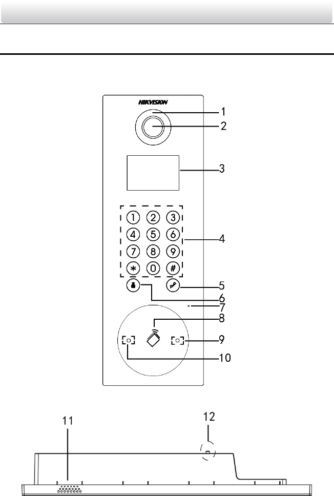
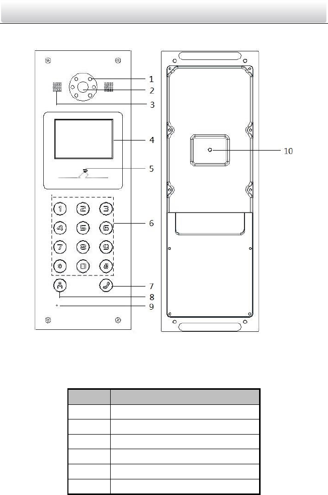
2.1 Front Panel and Keys (DS-KD8102-V)
Figure 2-1 Front Panel Keys
Figure 2-2 Side View
Video Intercom Door Station·User Manual
3
Table 2-1 Descriptions of Front Panel Keys
No.
Description
1
Low Illumination Supplement Light
2
Built-in Camera
3
LCD Display Screen
4
Numeric Keypad
5
Calling Button
6
Calling Center Key
7
Microphone
8
Card Induction Area
9
IR Emission
10
IR Receiver
11
Loudspeaker
12
Tamper Button
Video Intercom Door Station·User Manual
4
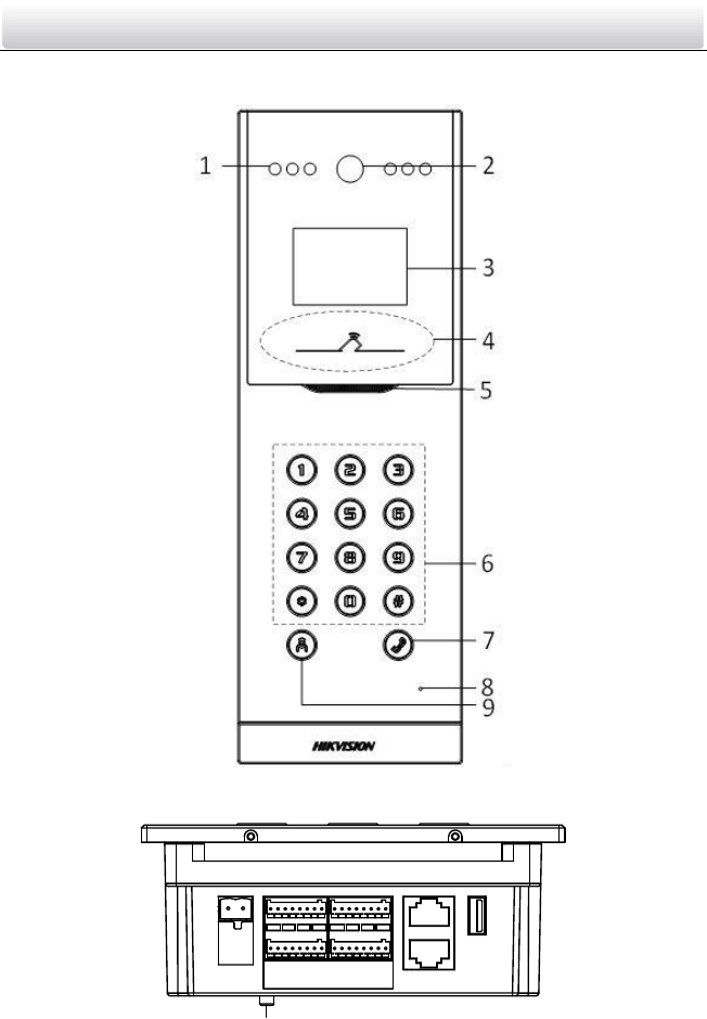
2.2 Front Panel and Keys (DS-KD8002-VM)
Figure 2-3 Front Panel Keys
10
Figure 2-4 Side View
Video Intercom Door Station·User Manual
5
Table 2-2 Descriptions of Front Panel Keys
No.
Description
1
Low Illumination Supplement Light
2
Built-in Camera
3
LCD Display Screen
4
Card Induction Area
5
Loudspeaker
6
Numeric Keypad
7
Calling Button
8
Microphone
9
Calling Center Key
10
Tamper Button
The appearance of the devices is only for reference, and the actual appearance of it
depends on the actual object.
Video Intercom Door Station·User Manual
6
2.3 Front Panel and Keys (DS-KD6002-VM)
Figure 2-5 Front Panel Keys and Rear Panel Keys
Table 2-3 Descriptions Keys
No.
Description
1
Low Illumination Supplement Light
2
Built-in Camera
3
Loudspeaker
4
LCD Display Screen
5
Card Induction Area
6
Numeric Keypad
Video Intercom Door Station·User Manual
7
No.
Description
7
Calling Button
8
Calling Center Key
9
Microphone
10
Tamper Button
The appearance of the devices is only for reference, and the actual appearance of it
depends on the actual object.
Video Intercom Door Station·User Manual
8
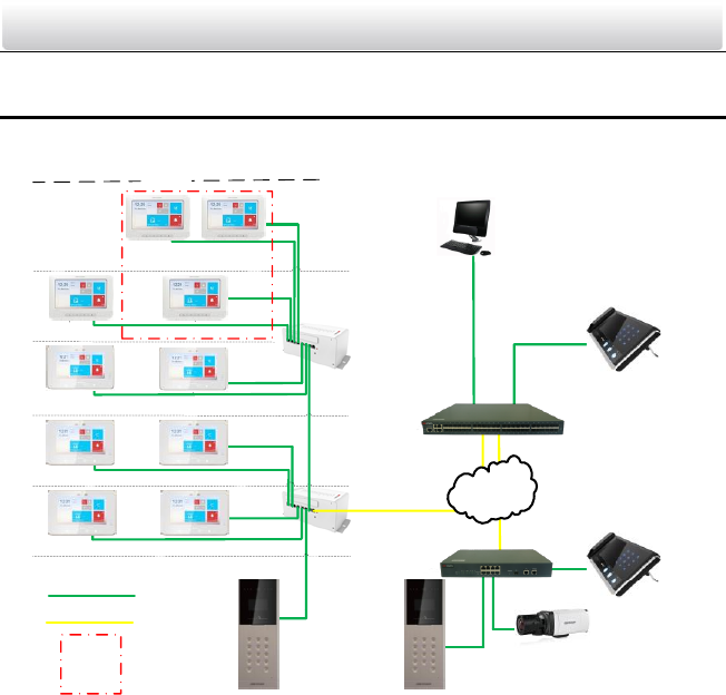
3 Typical Application
Please refer to the following figure for typical application of door station.
Switch
Client Software
Center Master Station
(Master Station)
Network Cable
Optical Fiber
Resident 2 Resident 1
Door Station
Resident 2 Resident 1
Resident 2 Resident 1
Building
IPC
Video/Audio
Distributor
Master Station
in Guard's Room
Outer Door Station
Estate LAN
Switch
Indoor
Extension 1
Indoor
Extension 2
Resident 2 Resident 1
Video/Audio
Distributor
One Resident
Figure 3-1 Typical Application of Door Station
Video Intercom Door Station·User Manual
9
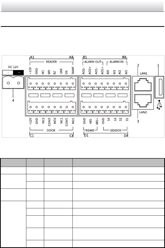
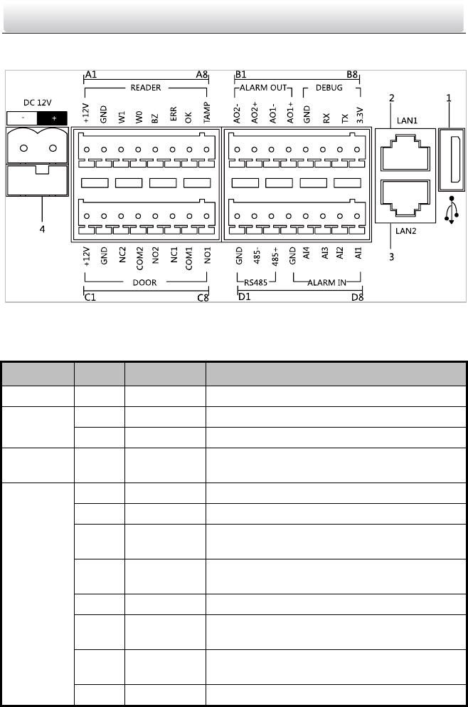
4 Terminals and Interfaces
4.1 Terminals and Interfaces of DS-KD8102-V/
DS-KD8002-VM
Figure 4-1 Terminals and Interfaces
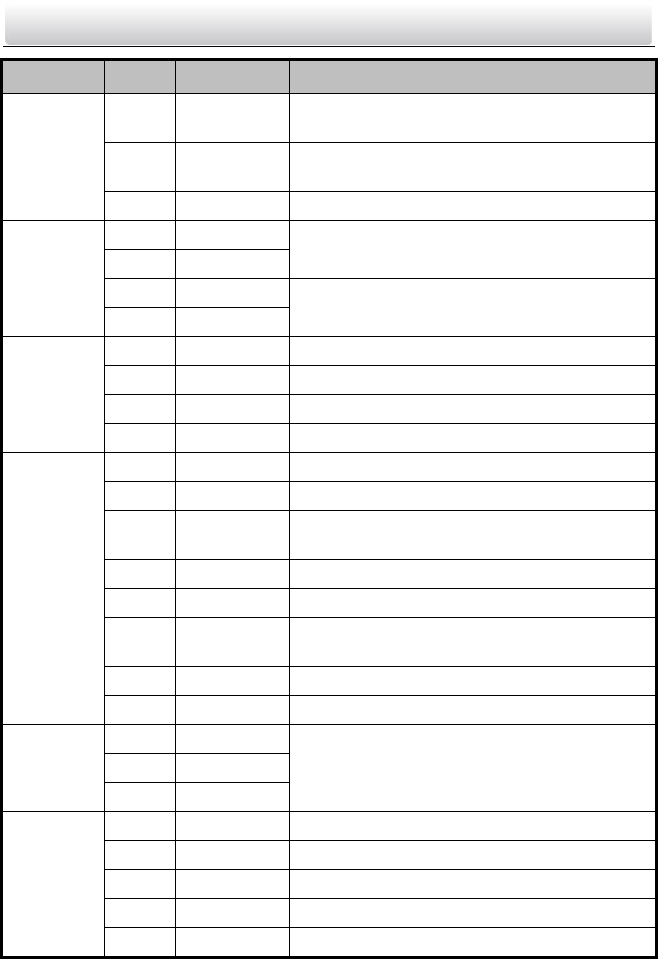
Table 4-1 Descriptions of Terminals and Interfaces
Name
No.
Interface
Description
USB
1
USB
USB Interface
LAN
2
LAN1
Network Interface
3
LAN2
Reserved
Power
Supply
4
DC 12V
DC 12V Power Supply Input
READER
A1
12V
Card Reader Power Supply Output
A2
GND
Grounding
A3
W1
Data Input Interface Wiegand Card Reader:
Data1
A4
W0
Data Input Interface Wiegand Card Reader:
Data0
A5
BZ
Card Reader Buzzer Output
Video Intercom Door Station·User Manual
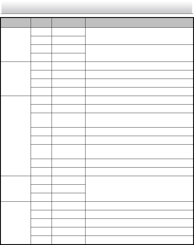
10
Name
No.
Interface
Description
A6
ERR
Card Reader Indicator Output (Invalid Card
Output)
A7
OK
Card Reader Indicator Output (Valid Card
Output)
A8
TAMP
Tamper-proof Input of Wiegand Card Reader
ALARM
OUT
B1
AO2-
Alarm Relay Output 2
B2
AO2+
B3
AO1-
Alarm Relay Output 1
B4
AO1+
ALARM IN
B5
AI4
Alarm Input 4
B6
AI3
Alarm Input 3
B7
AI2
Alarm Input 2
B8
AI1
Alarm Input 1
DOOR
C1
12V
Door Lock Power Supply Output
C2
GND
Grounding
C3
NC2
Door Lock Relay Output/Connect Electric Bolt
or Magnetic Lock
C4
COM2
Grounding Signal
C5
NO2
Door Lock Relay Output/Connect Electric Strike
C6
NC1
Door Lock Relay Output/Connect Electric Bolt
or Magnetic Lock
C7
COM1
Grounding Signal
C8
NO1
Door Lock Relay Output/Connect Electric Strike
RS485
D1
GND
Reserved
D2
485-
D3
485+
SENSOR
D4
GND
Grounding Signal
D5
S4
Door Magnetic Detection Input 4/Exit Button
D6
S3
Door Magnetic Detection Input 3/Exit Button
D7
S2
Door Magnetic Detection Input 2/Exit Button
D8
S1
Door Magnetic Detection Input 1/Exit Button
Video Intercom Door Station·User Manual
11
4.2 Terminals and Interfaces of DS-KD6002-VM
Figure 4-2 Terminals and Interfaces of DS-KD6002-VM
Table 4-2 Descriptions of Terminals and Interfaces
Name
No.
Interface
Description
USB
1
USB
USB Interface
LAN
2
LAN1
Network Interface
3
LAN2
Reserved
Power
Supply
4
DC 12V
DC 12V Power Supply Input
READER
A1
12V
Card Reader Power Supply Output
A2
GND
Grounding
A3
W1
Data Input Interface Wiegand Card Reader:
Data1
A4
W0
Data Input Interface Wiegand Card Reader:
Data0
A5
BZ
Card Reader Buzzer Output
A6
ERR
Card Reader Indicator Output (Invalid Card
Output)
A7
OK
Card Reader Indicator Output (Valid Card
Output)
A8
TAMP
Tamper-proof Input of Wiegand Card Reader
Video Intercom Door Station·User Manual
12
Name
No.
Interface
Description
ALARM
OUT
B1
AO2-
Alarm Relay Output 2
B2
AO2+
B3
AO1-
Alarm Relay Output 1
B4
AO1+
DEBUG
B5
GND
Grounding
B6
RX
Serial Port Debugging/Receive data
B7
TX
Serial Port Debugging/Send data
B8
3.3V
Serial Port Debugging/Power Supply
DOOR
C1
12V
Door Lock Power Supply Output
C2
GND
Grounding
C3
NC2
Door Lock Relay Output/Connect Electric Bolt
or Magnetic Lock
C4
COM2
Grounding Signal
C5
NO2
Door Lock Relay Output/Connect Electric Strike
C6
NC1
Door Lock Relay Output/ Connect Electric Bolt
or Magnetic Lock
C7
COM1
Grounding Signal
C8
NO1
Door Lock Relay Output/Connect Electric Strike
RS485
D1
GND
Reserved
D2
485-
D3
485+
ALARM IN
D4
GND
Grounding Signal
D5
AI4
Alarm Input 4
D6
AI3
Alarm Input 3
D7
AI2
Alarm Input 2
D8
AI1
Alarm Input 1
Video Intercom Door Station·User Manual
13
5 Installation and Wiring
5.1 Installation of DS-KD8102-V
To install the door station onto the wall, you are required to use a matched gang box.
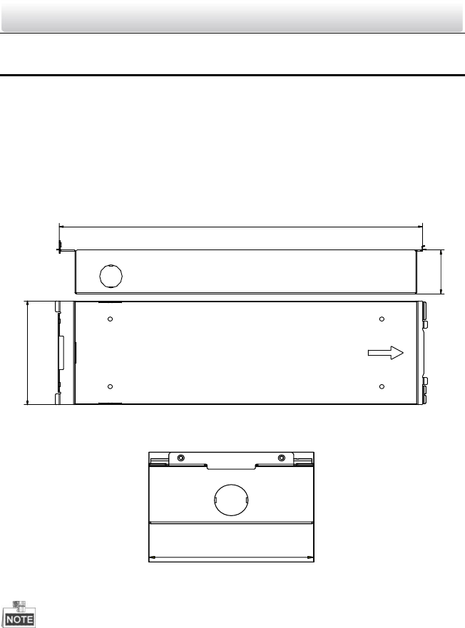
5.1.1 Gang Box for DS-KD8102-V
Refer to the following figures for the dimensions of gang box for DS-KD8102-V door
station.
123
47.5
404
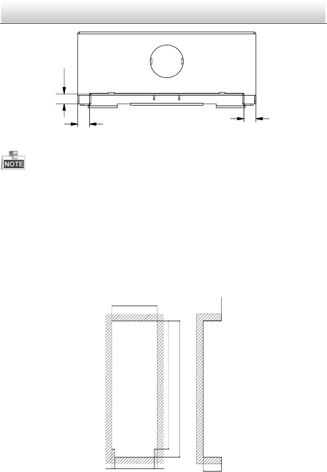
Figure 5-1 Front and Side View
123
Figure 5-2 Overhead (Plan) View
The dimension of gang box for model DS-KD8102-V door station is: 404 (length)×123
(width)×47.5 (depth) mm.
The dimensions above are for reference only. The actual size can be slightly different
from the theoretical dimension.
Video Intercom Door Station·User Manual
14
5.1.2 Wall Mounting with Gang Box of DS-KD8102-V
Steps:
1. Take the gang box and screws from the packing box.
2. Chisel a hole in the wall for inserting the gang box. The size of the hole should be
larger than that of the gang box. The suggested size of hole is 404.5 (length) × 123.5
(width) ×48 (depth) mm.
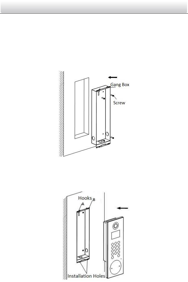
3. Insert the gang box into the hole and fix it with 4 PA4 screws, as shown in the figure
below.
Figure 5-3 Insert the Gang Box into the Wall
4. Make sure the edges of the gang box align to the wall.
5. Route the cables of the door station through the cable hole.
6. Put the door station into the gang box and hook the lock catches on the rear panel
onto the hook A and B of the gang box, as shown in the figure below.
Figure 5-4 Install the Door Station
Video Intercom Door Station·User Manual
15
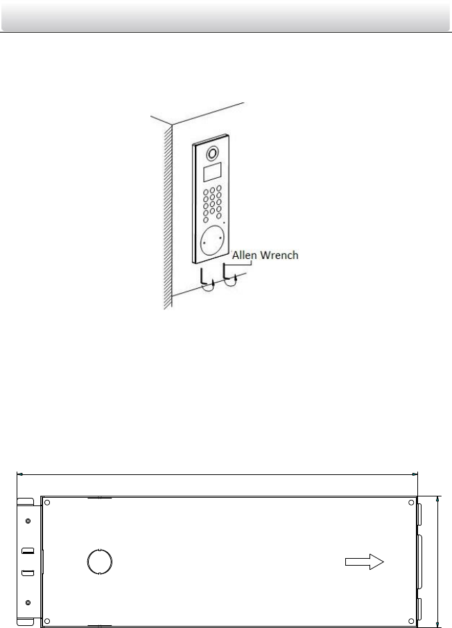
7. Pull the door station downward and then push it towards the inside to make sure it
fits the hole.
8. Tighten the screws of the door station with the Allen wrench in the package, as
shown in the figure below.
Figure 5-5 Tighten the Screws of Device
5.2 Installation of DS-KD8002-VM
To install the door station onto the wall, you are required to utilize a matched gang box.
5.2.1 Gang Box for DS-KD8002-VM
Please refer to the following figures for the dimensions of gang box for DS-KD8002-VM
door station.
407.5
135
Figure 5-6 Front View
Video Intercom Door Station·User Manual
16
99
7.6
Figure 5-7 Overhead (Plan) View
The dimension of gang box for model DS-KD8002-VM door station is: 407.5 mm × 135
mm × 55 mm.
The dimensions above are for reference only. The actual size can be slightly larger
than the theoretical dimension.
5.2.2 Wall Mounting with Gang Box of DS-KD8002-VM
1. Take the gang box and screws from the packing box.
2. Chisel a hole in the wall for inserting the gang box. The size of the hole should be
larger than that of the gang box. The suggested size of hole is 136 (length) × 408.5
(width) × 55.5 (depth) mm.
135.5
384
408
8.75 118 8.75 55
Figure 5-8 Dimensions of the Hole
Video Intercom Door Station·User Manual
17
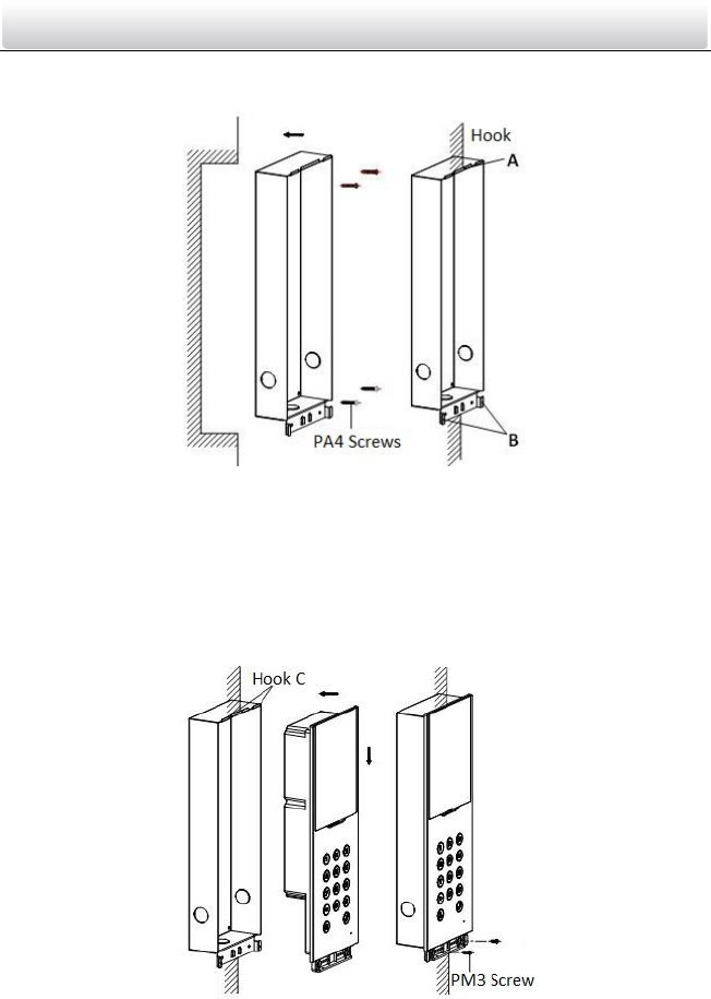
3. Insert the gang box into the hole and fix it with 4 PA4 screws, as shown in the figure
below.
Figure 5-9 Insert the Gang Box into the Wall
4. Make sure the edges of the gang box align to the wall and the hook A and hook B of
the gang box hook onto the wall.
5. Route the cables of the door station through the cable hole.
6. Insert the door station into the gang box and then move the door station downward
to hook the lock catches on the rear panel onto the hook C of the gang box.
7. Fix the door station with 2 PM3 screws, as shown in the figure below.
Figure 5-10 Install the Door Station
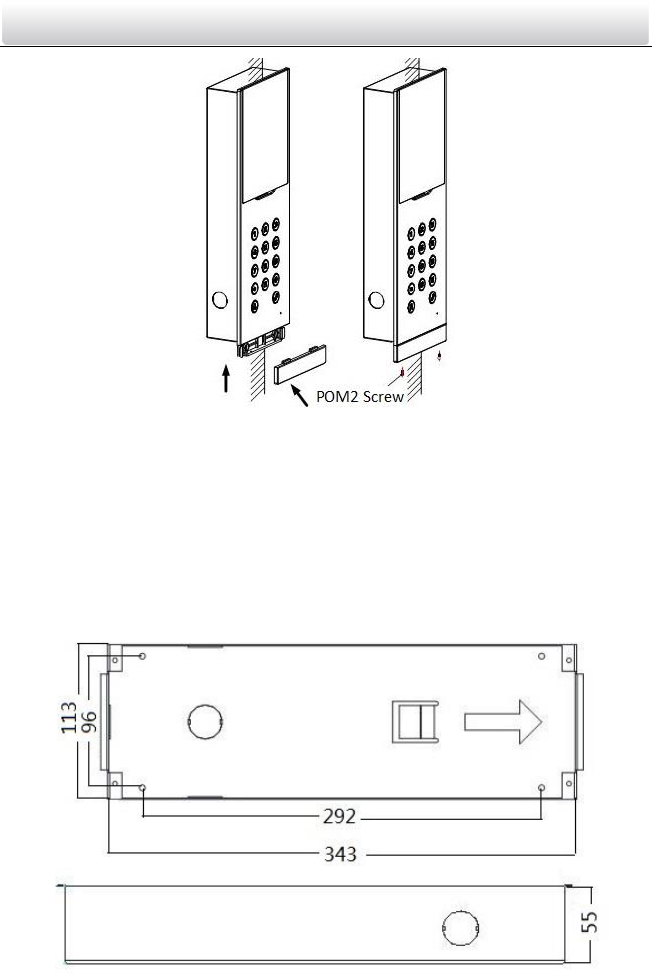
8. After fixing the door station onto the gang box, secure it by inserting the plate and
insert 2 POM2 screws, as shown in the figure below.
Video Intercom Door Station·User Manual
18
Figure 5-11 Secure the Door Station
5.3 Installation of DS-KD6002-VM
To install the door station onto the wall, you are required to use a matched gang box.
5.3.1 Gang Box for DS-KD6002-VM
Refer to the following figures for the dimensions of gang box for DS-KD6002-VM door
station.
Figure 5-12 Front and Side View
Video Intercom Door Station·User Manual
19
The dimension of gang box for model DS-KD6002-VM door station is: 343 (length)×
113(width)×55depth) mm.
The dimensions above are for reference only. The actual size can be slightly different
from the theoretical dimension.
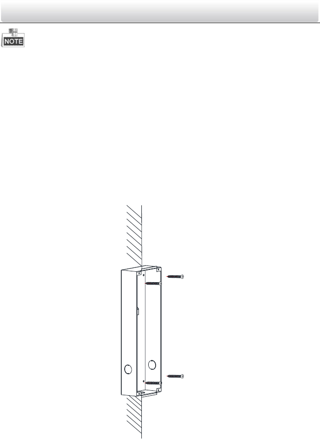
5.3.2 Wall Mounting with Gang Box of DS-KD6002-VM
Steps:
1. Take the gang box and screws from the packing box.
2. Chisel a hole in the wall for inserting the gang box. The size of the hole should be
larger than that of the gang box. The suggested size of hole is 343.5 (length) × 113.5
(width) × 55.5 (depth) mm.
3. Insert the gang box into the hole and fix it with 4 PA4 screws, as shown in the figure
below.
Screw
Screw
Figure 5-13 Insert the Gang Box into the Wall
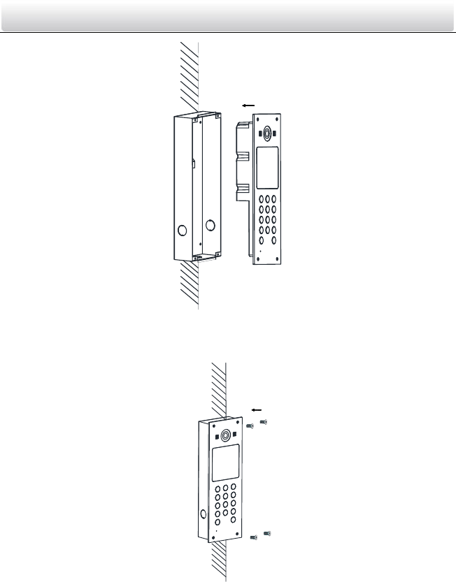
4. Make sure the edges of the gang box align to the wall.
5. Route the cables of the door station through the cable hole.
6. Put the door station into the gang box.
Video Intercom Door Station·User Manual
20
Figure 5-14 Install the Door Station
7. Fix the door station to the gang box with 4 crews.
Figure 5-15 Tighten the Screws of Device
5.4 Wiring Description
5.4.1 Door Lock Wiring
Video Intercom Door Station·User Manual
21
Figure 5-16 Door Lock Wiring
Terminal NO1/COM1 is set as default for accessing magnetic lock/electric bolt;
terminal NC1/COM1 is set as default for accessing electric strike.
To connect electric lock in terminal NO2/COM2/NC2, it is required to set the output
of terminal NO2/COM2/NC2 to be electric lock with Batch Configuration Tool or
iVMS-4200.
5.4.2 Door Magnetic Wiring
Door Magnetic Wiring for DS-KD8102-V/DS-KD8002-VM
For DS-KD8102-V/DS-KD8002-VM, there are two optional ways of door magnetic wiring.
Figure 5-17 Door Magnetic Wiring for DS-KD8102-V/DS-KD8002-VM (1)
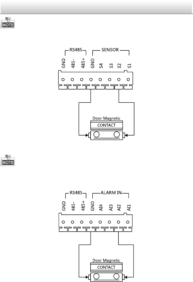
Video Intercom Door Station·User Manual
22
To connect the door magnetic, it is required to set the output of terminal AI2 to be door
magnetic with Batch Configuration Tool or iVMS-4200.
Figure 5-18 Door Magnetic Wiring for DS-KD8102-V/DS-KD8002-VM (2)
Terminal S2 is set as default for connecting door magnetic.
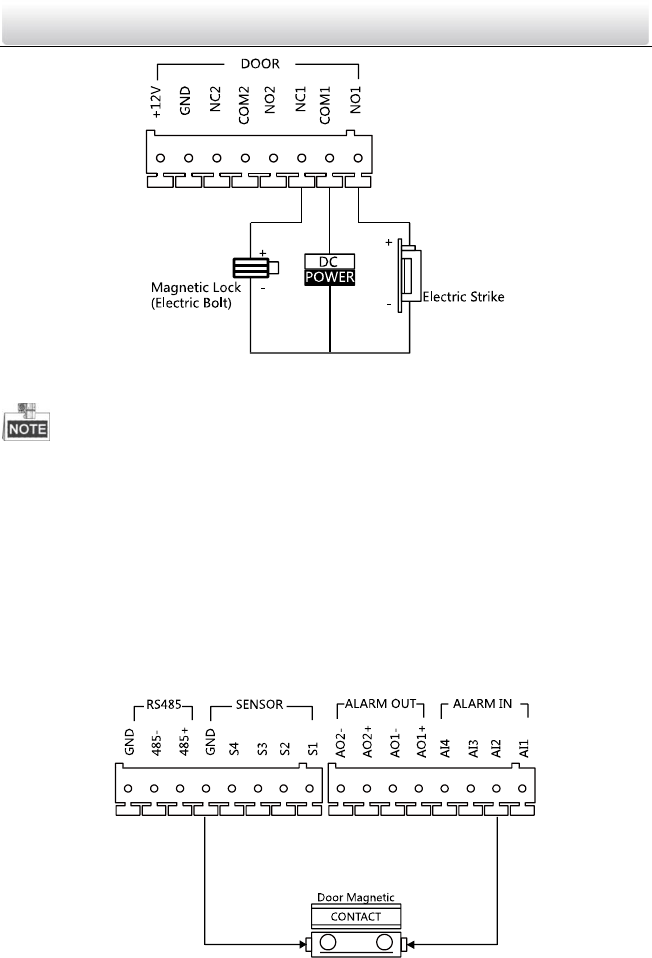
Door Magnetic Wiring for DS-KD6002-VM
Figure 5-19 Door Magnetic Wiring for DS-KD6002-VM
Video Intercom Door Station·User Manual
23
To connect the door magnetic, it is required to set the output of terminal AI2 to be door
magnetic with Batch Configuration Tool or iVMS-4200.
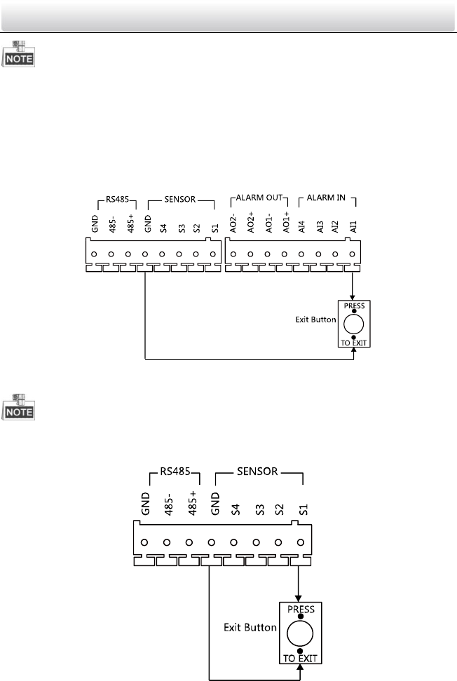
5.4.3 Exit Button Wiring
Exit Button Wiring for DS-KD8102-V/DS-KD8002-VM
For DS-KD8102-V/DS-KD8002-VM, there are two optional ways of exit button wiring.
Figure 5-20 Exit Button Wiring for DS-KD8102-V/DS-KD8002-VM (1)
To connect the exit button, it is required to set the output of terminal AI1 to be exit
button with Batch Configuration Tool or iVMS-4200.
Figure 5-21 Exit Button Wiring for DS-KD8102-V/DS-KD8002-VM (2)
Video Intercom Door Station·User Manual
24
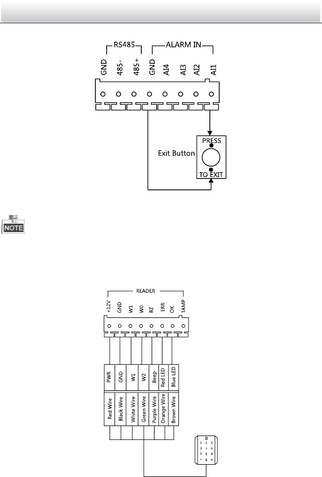
Exit Button Wiring for DS-KD6002-VM
Figure 5-22 Exit Button Wiring for DS-KD6002-VM
Terminal S1 is set as default for connecting exit button.
5.4.4 External Card Reader Wiring
Please refer to the following figure for external card reader wiring.
Figure 5-23 External Card Reader Wiring
Video Intercom Door Station·User Manual
25
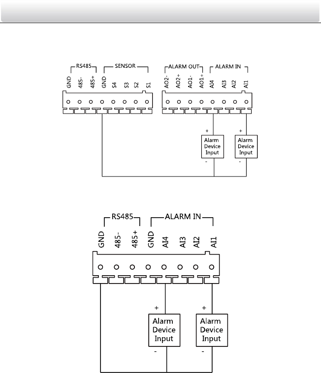
5.4.5 Alarm Device Input Wiring
Alarm Device Input Wiring for DS-KD8102-V/DS-KD8002-VM
Figure 5-24 Alarm Device Input Wiring for DS-KD8102-V/DS-KD8002-VM
Alarm Device Input Wiring for DS-KD6002-VM
Figure 5-25 Alarm Device Input Wiring for DS-KD6002-VM
Video Intercom Door Station·User Manual
26
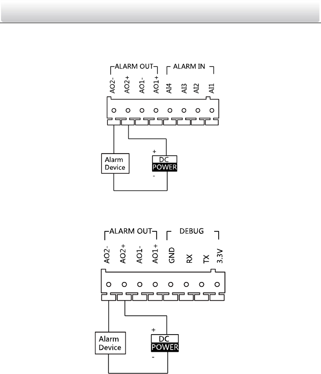
5.4.6 Alarm Device Output Wiring
Alarm Device Output Wiring for DS-KD8102-V/DS-KD8002-VM
Figure 5-26 Alarm Device Output Wiring for DS-KD8102-V/DS-KD8002-VM
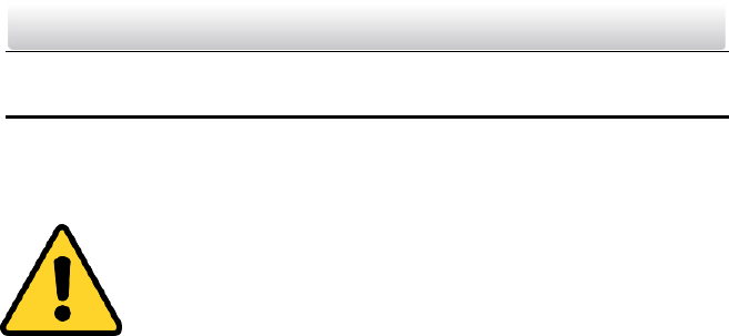
Alarm Device Output Wiring for DS-KD6002-VM
Figure 5-27 Alarm Device Output Wiring for DS-KD6002-VM
Video Intercom Door Station·User Manual
27
6 Before You Start
For the first time use of the device, you are required to activate the device and set the
device password. You can activate the device via internet with Batch Configuration Tool,
or with iVMS-4200 client software, or with Video Intercom Set-up Tool.
To activate the device with Video Intercom Device Set-up Tool, refer to
Chapter 7.
To activate the device with Batch Configuration Tool or iVMS-4200, refer
to Chapter 8 and Chapter 9.
To activate the device locally, refer to Chapter 10.
To configure the key parameters of device on the user interface of door station, you are
required to enter the admin password. Here the admin password refers to the
configuration password.
The default admin password is 888999.
You can set the login password of the device by yourself.
You must change the default credential to protect against unauthorized access to the
product. Please refer to 8.4.2 and 10.5 for changing password.
Video Intercom Door Station·User Manual
28
7 Video Intercom Device Set-up Tool
Purpose:
You can assign the device to the community, active and set the device by using the video
intercom device set-up tool.
7.1 Setting a Community Structure
Purpose:
You can set a community structure, based on the real community situation, on the video
intercom device set-up tool, and then assign devices to the community accordingly.
The concept Project, be self-defined in every individual application, is used to describe a
collection of communities. A project can involve multi communities. While if there is
only 1 community in a project, the default project No. is 1.
7.1.1 Setting Project
Steps:
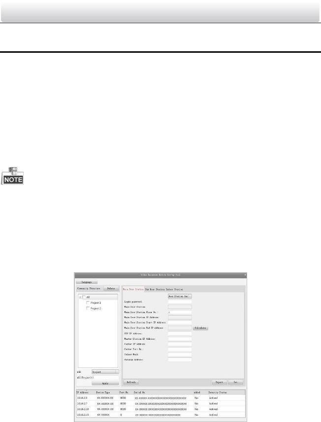
1. Run the software to enter the main interface of video intercom device set-up tool.
Figure 7-1 Main Interface of Device Set-up Tool
2. Select Project from the drop-down list and enter a number in the textbox to set the
amount of project.
Video Intercom Door Station·User Manual
29
Figure 7-2 Project Settings
3. Click the Apply button to enable the settings.
The default amount of project is 1 if the amount is not set in the textbox.
7.1.2 Setting Community
Steps:
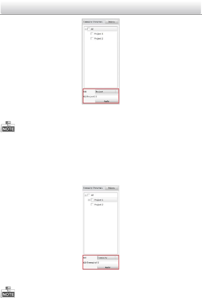
1. Check the checkbox of a certain project from the community structure.
2. Select Community from the drop-down list and enter a number in the textbox to set
the amount of community.
Figure 7-3 Community Settings
3. Click the Apply button to enable the settings.
Video Intercom Door Station·User Manual
30
If you check the checkbox of All, then all projects in the community structure will be
selected, and will be added the same amount of community.
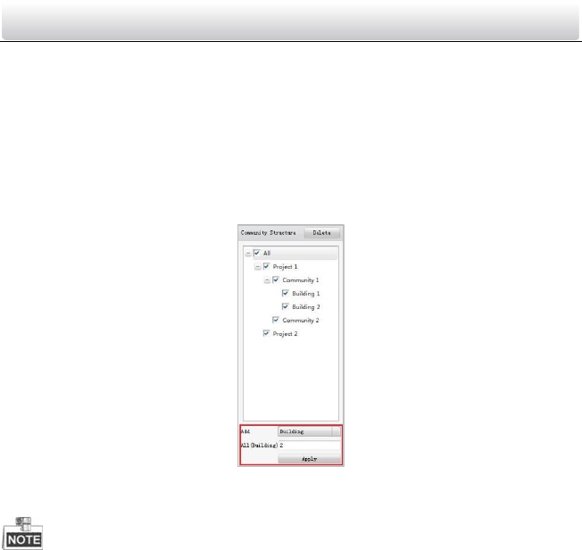
7.1.3 Setting Building
Steps:
1. Check the checkbox of a certain community from the community structure.
2. Select Building from the drop-down list and enter a number in the textbox to set the
amount of building.
Figure 7-4 Building Settings
3. Click the Apply button to enable the settings.
If you check the checkbox of All, then all communities in the community structure will
be added the same amount of building.
If you check the checkbox of a certain project, then all communities in the selected
project will be added the same amount of building.
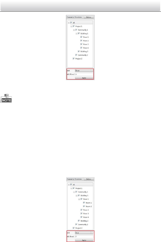
7.1.4 Setting Floor
Steps:
1. Check the checkbox of a certain building from the community structure.
2. Select Floor from the drop-down list and enter a number in the textbox to set the
amount of floor.
Video Intercom Door Station·User Manual
31
Figure 7-5 Floor Settings
3. Click the Apply button to enable the settings.
If you check the checkbox of All, then all buildings in the community structure will be
added the same amount of floor.
If you check the checkbox of a certain project, then all buildings in the selected
project will be added the same amount of floor.
If you check the checkbox of a certain community, then all buildings in the selected
community will be added the same amount of floor.
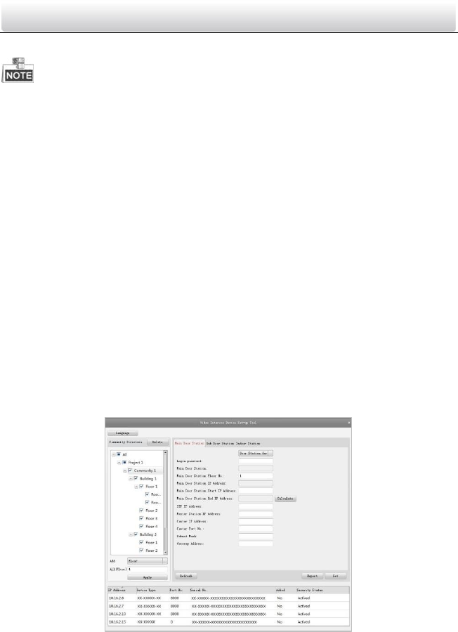
7.1.5 Setting Room
Steps:
1. Check the checkbox of a certain floor from the community structure.
2. Select Room from the drop-down list and enter a number in the textbox to set the
amount of room
Figure 7-6 Room Settings
Video Intercom Door Station·User Manual
32
3. Click the Apply button to enable the settings.
If you check the checkbox of All, then all floors in the community structure will be
selected, and will be added the same amount of room.
If you check the checkbox of a certain project, then all floors in the selected project
will be added the same amount of floor.
If you check the checkbox of a certain community, then all floors in the selected
community will be added the same amount of floor.
If you check the checkbox of a certain building, then all floors in the selected building
will be added the same amount of floor.
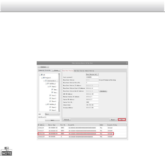
7.2 Activating and Setting Main Door Station
Purpose:
You can activate the online main door station, and configure the building number of
online main door station.
Before You Start:
Press the Main Door Station tab to switch to the main door station settings.
Steps:
1. Select the community to configure the building numnber for the main door station.
Figure 7-7 Selecting Community
2. Select the door station type from the drop-down list: door station for unit or door
station for villa.
3. Enter the main door station start IP address.
Video Intercom Door Station·User Manual
33
4. Click the Calculate button to generate the main door station end IP address
automatically.
5. Set the main door station floor No..
6. Enter the SIP IP address, master station IP address, center IP address, center port No.,
subnet mask, and gateway address.
7. Click the Refresh button to view the online indoor station of the same segment.
8. Select a door station and enter the login password.
9. Click the Set button to accomplish the settings of main door station.
Figure 7-8 Main Door Station Settings Interface
The default main door station floor No. is 1.
You can select one project or multiple projects; one community or multiple
communities; one building or multiple buildings.
The Main Door Station IP Address is usually set to be the same as Start IP Address of
main door station.
If the main door station is not activated, create a login password and enter it in the
textbox to activate the device.
If the main door station is not activated, the device is configured and activated
simultaneously by clicking the Set button.
When the device is successfully configured, it prompts the note: Configuring main
door station parameters succeeded.
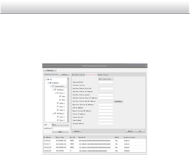
7.3 Activating and Setting Sub Door Station
Purpose:
Video Intercom Door Station·User Manual
34
You can activate the online sub door station, and configure the number of online sub
door station.
Before You Start:
Press the Sub Door Station tab to switch to the sub door station settings.
Steps:
1. Select the community to configure the numnber for the sub door station.
Figure 7-9 Selecting Community
2. Select the door station type from the drop-down list: door station for unit or door
station for villa.
3. Set the sub door station floor No..
4. Set the sub door station amount.
5. Enter the sub door station start IP address.
6. Click the Calculate button to generate the sub door station end IP address
automatically according to the sub door station amount.
7. Enter the main door station IP address, SIP IP address, master station IP address,
center IP address, center port No., subnet mask, and gateway address.
8. Click the Refresh button to view the online indoor station of the same segment.
9. Select a door station and enter the login password.
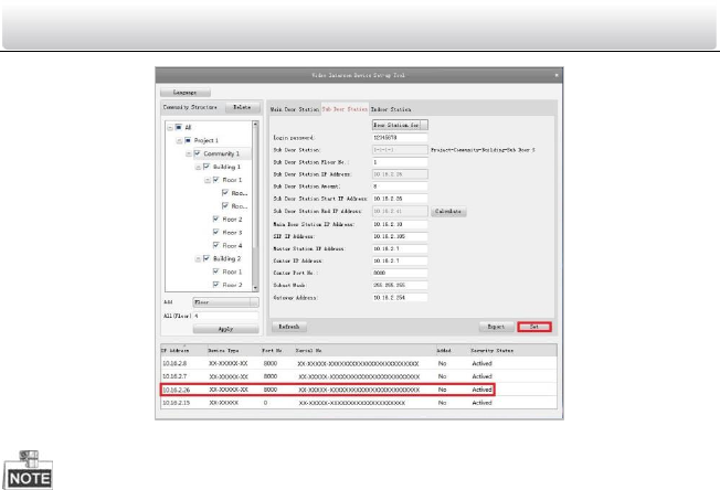
10. Click the Set button to accomplish the settings of sub door station.
Video Intercom Door Station·User Manual
35
Figure 7-10 Sub Door Station Settings Interface
The default sub door station floor No. is 1.
The sub door station amount should be no higher than 8.
You can select one project or multiple projects; one community or multiple
communities; one building or multiple buildings.
The Sub Door Station IP Address is usually set to be the same as Start IP Address of
sub door station.
If the sub door station is not activated, create a login password and enter it in the
textbox to activate the device.
If the sub door station is not activated, the device is configured and activated
simultaneously by clicking the Set button.
When the device is successfully configured, it prompts the note: Configuring sub door
station parameters succeeded.
Video Intercom Door Station·User Manual
36
8 Batch Configuration Software
8.1 Activating Device Remotely
Purpose:
The device cannot be operated until it is activated. You can remotely activate the device
via Batch Configuration Tool or via iVMS-4200 client. Here take the Batch Configuration
Tool as example, and for further information, please refer to the user manual in the disk.
Steps:
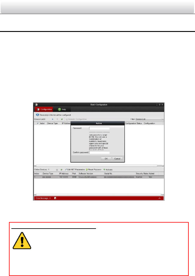
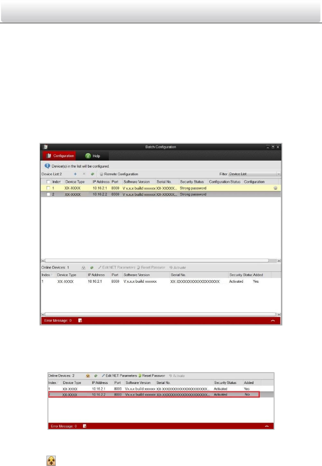
1. Run the software, and select the inactivated device from the online devices and click
the Activate button.
Figure 8-1 Activating Device
2. Create a password, and enter the password into the password field.
STRONG PASSWORD RECOMMENDED– We highly recommend you create a
strong password of your own choosing (Using a minimum of 8
characters, including at least three of the following categories:
upper case letters, lower case letters, numbers, and special
characters.) in order to increase the security of your product. And we
recommend you reset your password regularly, especially in the high security
system, resetting the password monthly or weekly can better protect your
product.
3. Confirm the password.
4. Click the OK button to activate the device.
Video Intercom Door Station·User Manual
37
When the device is not activated, the basic operation and remote operation of device
cannot be performed.
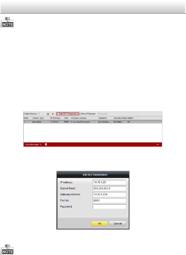
8.2 Editing Network Parameters
Purpose:
You can edit the network parameters of online devices.
Steps:
1. Select an online device in the online devices list in the lower part of the batch
configuration software interface.
2. Click the Edit NET Parameters button.
Figure 8-2 Edit NET Parameters
3. Enter a new IP address, subnet mask, gateway address, port No. and the password.
4. Click the OK button to accomplish the editing.
Figure 8-3 Edit Network Parameters
The default port No. is 8000.
After editing the network parameters of device, you should add the devices to the
device list again.
Video Intercom Door Station·User Manual
38
8.3 Adding Device
The software provides 4 ways for adding the devices. You can add the active online
devices within your subnet, add devices by IP address, add devices by IP segment or add
devices by device port No. range.
8.3.1 Adding Online Devices
Steps:
1. Run the software to enter the main interface of video intercom batch configuration
tool software.
Figure 8-4 Main Interface of Batch Configuration Software
2. Select an online device or hold the Ctrl or Shift key to select multiple devices in the
online devices list in the lower part of the batch configuration software interface.
Figure 8-5 Online Devices Interface
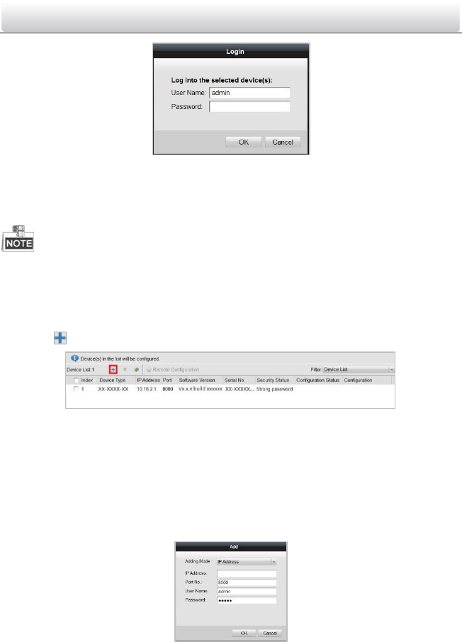
3. Click the button to pop up the login dialog box.
Video Intercom Door Station·User Manual
39
Figure 8-6 Login Dialog Box
4. Enter the user name and password.
5. Click the OK button to save the settings.
Only the devices that are successfully logged in will be added to the device list for
configuration.
8.3.2 Adding by IP Address, IP Segment or Port No.
Click the button to pop up the adding devices dialog box.
Figure 8-7 Adding Button
Adding by IP Address
Purpose:
You can add the device by entering IP address.
Steps:
1. Select IP Address in the adding mode drop-down list.
2. Enter the IP address, and set the port No., user name and password of the device.
Figure 8-8 Adding by IP Address
3. Click the OK button to add the device to the device list.
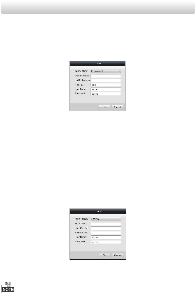
Adding by IP Segment
Video Intercom Door Station·User Manual
40
Purpose:
You can add many devices at once whose IP addresses are among the IP segment.
Steps:
1. Select IP Segment in the adding mode drop-down list.
2. Set the Start IP Address and End IP Address.
3. Enter port No., user name, and password.
Figure 8-9 Adding by IP Segment
4. Click the OK button to search and add the devices whose IP addresses are within the
range of the defined IP segment to the device list.
Adding by Port No.
Purpose:
By adding devices by port No., you can add multiple devices which access to the
network via port mapping. Devices, with the same IP address but different port numbers,
can be added in this way.
Steps:
1. Select Port No. in the adding mode drop-down list.
2. Enter the IP address.
3. Set the Start Port No. and the End Port No..
4. Enter the user name and password.
Figure 8-10 Adding by Port No.
5. Click the OK button to search and add the devices of which port numbers are within
the defined port No. range to the device list.
Video Intercom Door Station·User Manual
41
You cannot add the device(s) to the device list if the user name and password are not
identical.
When you add devices by IP Address, IP Segment or Port No., the devices should be
online devices.
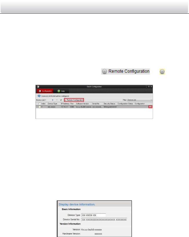
8.4 Remote Configuration
In the device list area, select a device and click or to enter
the remote configuration interface.
Figure 8-11 Remote Configuration
8.4.1 System
Click the System button on the remote configuration interface to display the device
information: Device Information, General, Time, System Maintenance, User, RS485.
Device Information
Click the Device Information button to enter device basic information interface. You can
view basic information (the device type, and serial No.), and version information of the
device.
Figure 8-12 Device Information Interface
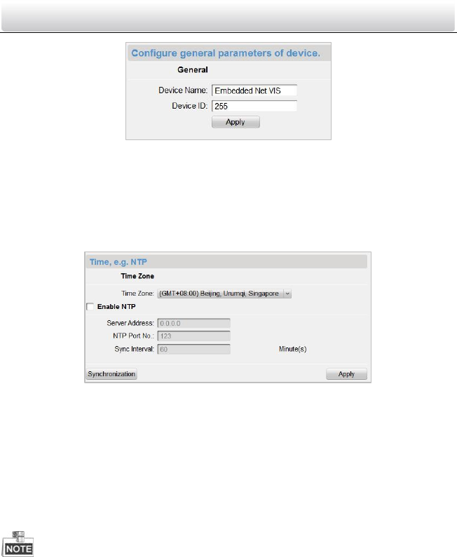
General
Click the General button to enter device general parameters settings interface. You can
view and edit the device name and device ID.
Video Intercom Door Station·User Manual
42
Figure 8-13 Device General Parameters Settings Interface
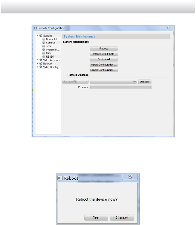
Time
Steps:
1. Click the Time button to enter the device time settings interface.
Figure 8-14 Time Settings Interface
2. Select Time Zone or Enable NTP
Time Zone
1) Select a time zone from the drop-down list menu.
2) Click the Synchronization button.
NTP
1) Check the checkbox of Enable NTP to enable NTP.
2) Enter the server address, NTP port, and synchronization interval.
3. Click the Apply button to save and realize the time settings.
The default port No. is 123.
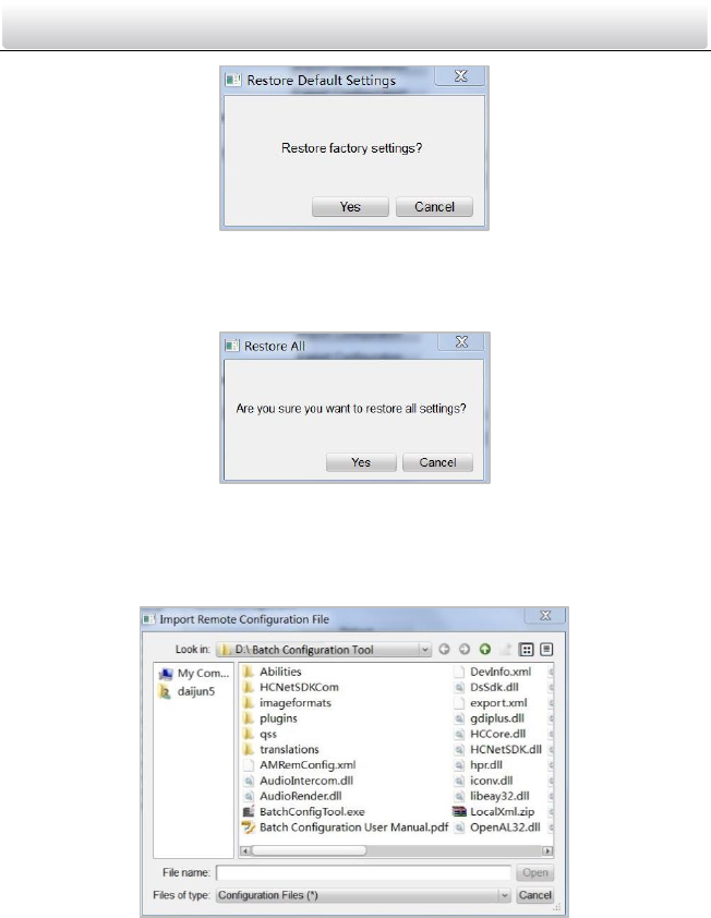
System Maintenance
Purpose:
You can operate the system management and remote upgrading on the system
maintenance interface.
Steps:
Video Intercom Door Station·User Manual
43
1. Click the System Maintenance button to enter the system maintenance interface.
Figure 8-15 System Maintenance Interface
2. Select System Management or Remote Upgrade.
System Management
• Reboot
1) Click the Reboot button to pop up the reboot dialog box.
Figure 8-16 Reboot
2) Click the Yes button to reboot the system.
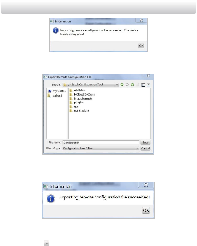
• Restore Default Settings
1) Click the Restore Default Settings button to pop up the restore default
settings dialog box.
Video Intercom Door Station·User Manual
44
Figure 8-17 Restore Default Settings
2) Click the Yes button to restore the default parameters.
• Restore All
1) Click the Restore All button to pop up the restore all settings dialog box.
Figure 8-18 Restore All Settings
2) Click the Yes button to restore all parameters of device and reset the device to
inactive status.
• Import Configuration File
1) Click the Import Configuration File button to pop up the import file window.
Figure 8-19 Import Configuration File Window
2) Select the path of remote configuration files.
3) Click the Open button to import the remote configuration file and pop up a
reboot information dialogue box.
Video Intercom Door Station·User Manual
45
Figure 8-20 Reboot Information
• Export Configuration File
1) Click the Export Configuration File button to pop up the export file window.
Figure 8-21 Export Configuration File Window
2) Select the save path of remote configuration files.
3) Click the Save button to export the configuration file, and pop up an
information box for exporting.
Figure 8-22 Information Box for Exporting
Remote Upgrade
• Reboot
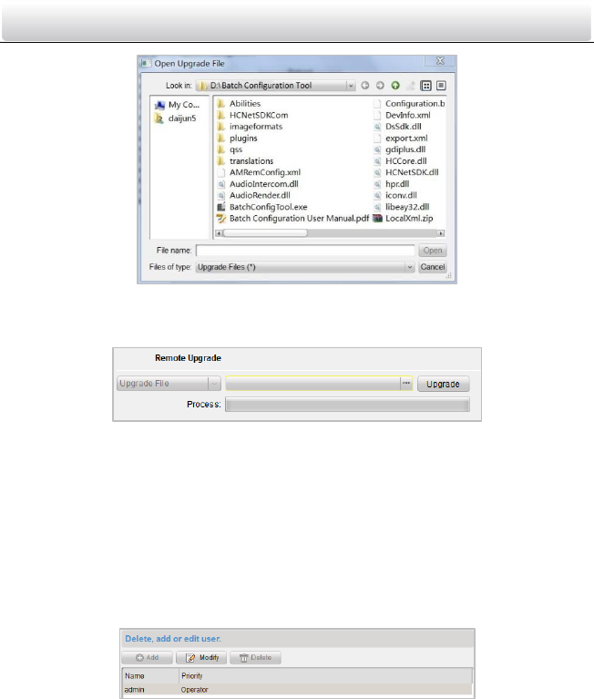
1) Click the button to pop up the window for opening upgrade file.
Video Intercom Door Station·User Manual
46
Figure 8-23 Window for Opening Upgrade File
2) Select the upgrade file, and click the Open button.
3) Click the Upgrade button to remotely upgrade the device.
Figure 8-24 Remote Upgrade
User
Purpose:
You can edit the password to log in the device.
Steps:
Steps:
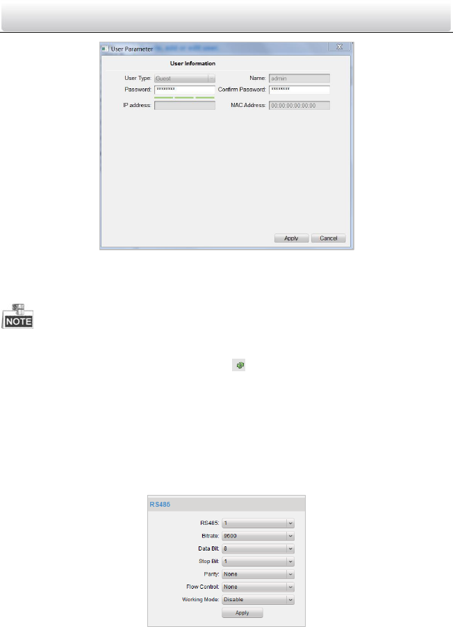
1. Click the User button to enter the user information editing interface
Figure 8-25 User Information Editing Interface
2. Select the user to edit and click the Modify button to enter the user parameter
interface.
Video Intercom Door Station·User Manual
47
Figure 8-26 User Parameter Interface
3. Enter the new password, and confirm it.
4. Click the Apply button to realize the editing of password.
The new password and confirm password should be identical.
After editing the password of device, click button from the device list, the added
device will not be there. You should add the device again with new password to
operate the remote configuration.
RS485
Click the RS485 button to enter the RS485 setting interface. You can view and edit the
RS485 parameters of the device.
Figure 8-27 RS485 Parameters
Video Intercom Door Station·User Manual
48
8.4.2 Video Intercom
Device Number Configuration
Steps:
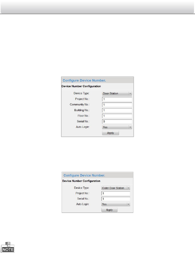
1. Click the Device Information button to enter device number configuration interface.
Door Station
1) Select door station from the drop-down list of the device type
Figure 8-28 Device Number Configuration (Door Station)
2) Enter the project No., community No., building No., floor No., and serial No.
3) Select Yes or No from the drop-down list menu of auto login.
Outer Door Station
1) Select outer door station from the drop-down list of the device type.
Figure 8-29 Device Number Configuration (Outer Door Station)
2) Enter the project No., and serial No.
3) Select Yes or No from the drop-down list menu of auto login.
2. Click the Apply button to enable the device number configuration.
For door station, the default serial No. is 0. When the serial No. is 0, the device is
main door station, and when the serial No. is larger than 0, the device is sub door
station.
For each main door station, at most 8 sub door stations can be installed.
For outer door station, the serial No. cannot be set as 0.
Video Intercom Door Station·User Manual
49
Time Parameters
Steps:
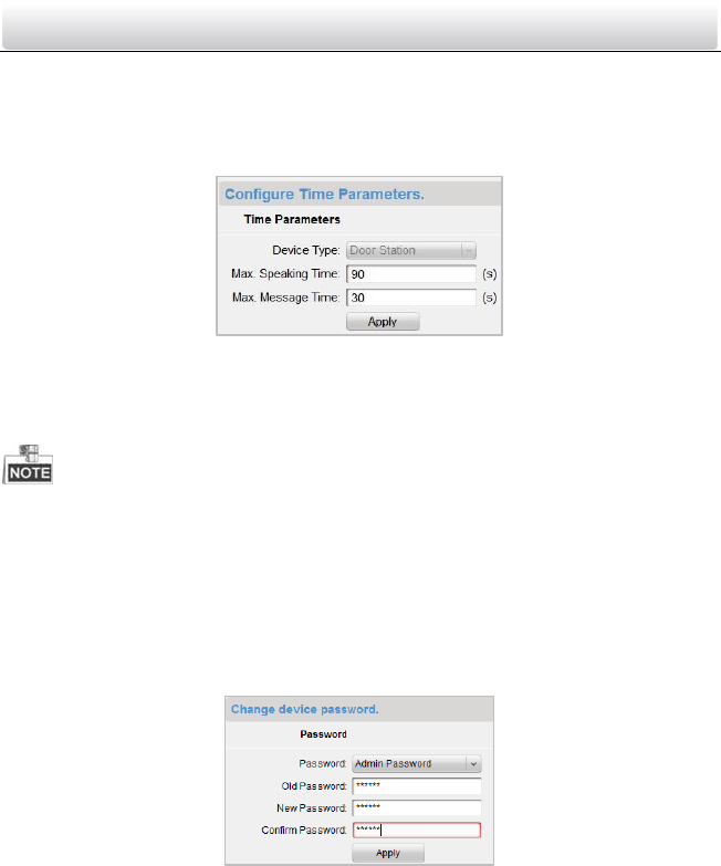
1. Click the Time Parameters button to enter time parameters settings interface.
Figure 8-30 Time Parameters Settings Interface
2. Set the maximum speaking time and the maximum message time.
3. Click the Apply button to enable the time parameters settings.
Maximum speaking time cannot exceed 120s; and maximum visitor message time
cannot exceed 60s.
Password
Steps:
1. Click the Password button to enter password changing interface.
Figure 8-31 Password Changing Interface
2. Select the admin password, arming/disarming password, unlocking password, or
duress code from the drop-down list menu.
3. Enter the old password.
4. Set a new password.
5. Confirm the new password.
6. Click the Apply button to enable the password changing settings.
Video Intercom Door Station·User Manual
50
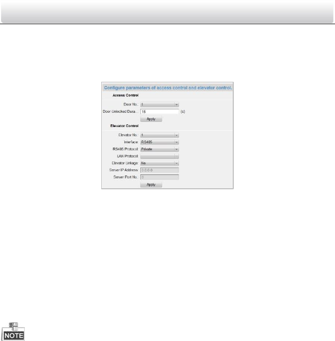
Access Control and Elevator
Steps:
1. Click the Access Control and Elevator button to enter password changing interface.
Figure 8-32 Access Control and Elevator Settings Interface
2. Set corresponding parameters on the access control and elevator settings interface.
Access Control
1) Select the door No.
2) Set the door-unlocked duration.
3) Click the Apply button to enable the settings.
Elevator Control
1) Select the elevator No., interface, RS485 protocol.
2) Select Yes/No of the elevator linkage.
3) Enter the server IP address and server port No..
4) Click the Apply button to enable the settings.
Only main door station supports the elevator control function.
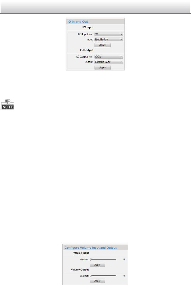
I/O Input and Output
Steps:
1. Click the I/O In and Out button to enter the I/O input and output interface.
Video Intercom Door Station·User Manual
51
Figure 8-33 I/O In and Out Interface
2. Select I/O input No., input mode, output No., and output mode.
3. Click the Apply button to enable the settings.
For DS-KD8102-V/DS-KD8002-VM, there are 8 I/O input terminals. Terminal 1~4
correspond to SENSOR interfaces (S1, S2, S3, S4) of door station. Terminal 5~8
correspond to AlARM IN interfaces (AI1, AI2, AI3, AI4) of door station. You can select
an I/O input No. (S1, S2, S3, S4, AI1, AI2, AI3, AI4) from the drop-down list as door
magnetic or exit button.
For DS-KD6002-VM, there are 4 I/O input terminals, corresponding to ALARM IN
interfaces (AI1, AI2, AI3, AI4) of door station. You can select an I/O input No. (AI1, AI2,
AI3, AI4) from the drop-down list as door magnetic or exit button.
There are 4 I/O output terminals. Terminal 1~2 correspond to DOOR interfaces
(NO1/COM1/NC1; NO2/COM2/NC2) of door station. You can enable/disable I/O
output by selecting from the drop-down list. Terminal 3~4 correspond to ALARM OUT
interfaces (AO1+, AO1-; AO2+, AO2-).
Volume In and Out
Click the Volume In and Out button to enter the volume in and out interface. Slide the
slider to adjust the volume input and volume output.
Figure 8-34 Volume In and Out Interface
Video Intercom Door Station·User Manual
52
8.4.3 Network
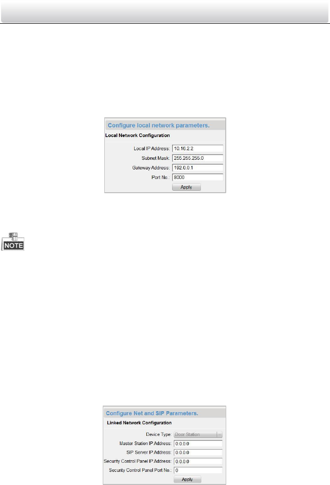
Local Network Configuration
Steps:
1. Click the Local Network Configuration button to enter the local network
configuration interface.
Figure 8-35 Local Network Configuration Interface
2. Enter the local IP address, subnet mask, gateway address, and port No..
3. Click the Apply button to enable the settings.
The default port No. is 8000.
After editing the local network parameters of device, you should add the devices to
the device list again.
Linked Devices Network Configuration
Purpose:
On the linked devices network configuration interface, you can configure the network
parameters of master stations, SIP servers and management centers of the same LAN.
Steps:
1. Click the Linked Device Network Configuration button to enter the devices network
configuration interface.
Figure 8-36 Linked Devices Network Configuration Interface
2. Select the device type from the drop-down list.
Video Intercom Door Station·User Manual
53
3. Enter the IP address of the master station, SIP server address, management center IP
address, and management center port No..
4. Click the Apply button to link the master station, SIP server and management center
to the device.
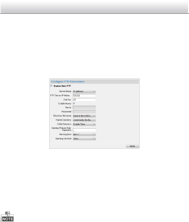
FTP
Steps:
1. Click the FTP button to enter the FTP parameters interface.
Figure 8-37 FTP Parameters Interface
2. Check the checkbox of Enable Main FTP.
3. Select IP address from the drop-down list of server mode.
4. Enter the FTP server address, and port No..
5. Check the checkbox to enable the anonymity (optional).
6. Enter the name and password.
7. Select the directory structure and set the separator, naming item, and naming
element.
8. Click the Apply button to enable the FTP parameters settings.
The default port No. is 21.
To enable anonymity or not is according to whether the FTP server enables
anonymity.
After configuring the FTP parameters, the captured pictures of door station will be
uploaded to the FTP server automatically.
Doorphone does not support the FTP function.
Video Intercom Door Station·User Manual
54
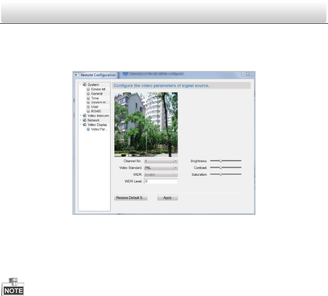
8.4.4 Video Display
Steps:
1. Click the Video Display button to enter the video parameters interface.
Figure 8-38 Video Parameters Interface
2. Select the channel No..
3. Select the video format (PAL and NTSC can be selected).
4. Set the brightness, contrast, and saturation of the video.
5. Click the Apply button to enable the settings.
Click the Restore Default Settings button to restore all parameters excluding network
parameters to the factory settings.
Video Intercom Door Station·User Manual
55
9 Setting the Door Station via iVMS-4200
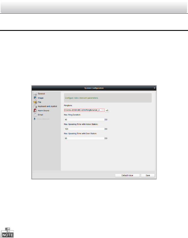
9.1 System Configuration
After running the iVMS-4200, enter Control Panel -> Maintenance and Management ->
System Configuration -> Video Intercom to configure the video intercom parameters
accordingly.
You can configure the ringtone, Max. ring duration, Max. speaking time with indoor
station and Max. speaking time with door station.
Figure 9-1 System Configuration Interface
9.2 Device Management
Device management includes device activation, adding device, editing device, deleting
device and remote configuration. Please refer to Chapter 8 Batch Configuration Tool for
detailed information.
To add door station to iVMS-4200 client software, you should add it as encoding
device.
You can add at most 16 door stations to iVMS-4200 client software.
9.3 Live View of Device
Steps:
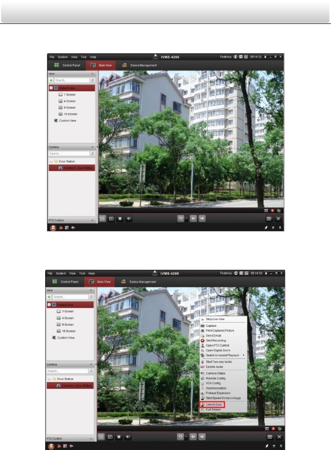
Video Intercom Door Station·User Manual
56
1. Enter the main view interface of iVMS-4200 client software to display the live view of
door station.
Figure 9-2 Live View of Door Station (D Series)
2. Right click on the live view interface to display the menu and select Unlock Door to
remote unlock the door.
Figure 9-3 Menu of Live View Interface
Video Intercom Door Station·User Manual
57
9.4 Picture Storage on Storage Server
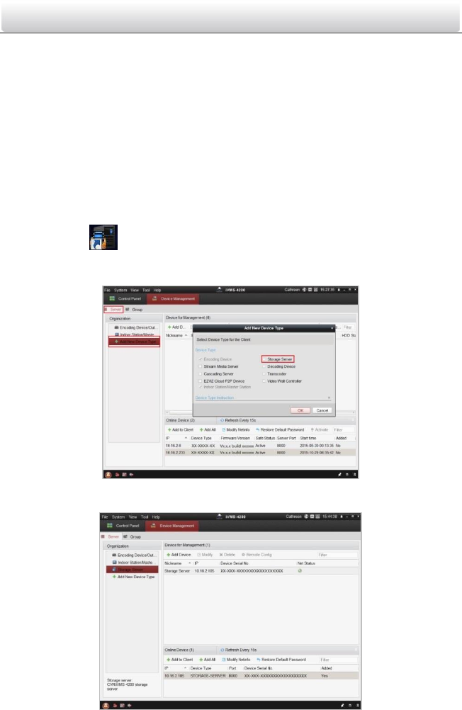
9.4.1 Adding Storage Server
Purpose:
When the device is under armed status, it will capture the picture automatically after
unlocking the door. The captured picture can be uploaded and stored in the storage
server.
Before you start:
The storage server application software needs to be installed and it is packed in the
iVMS-4200 software package. When installing the iVMS-4200, check the checkbox
Storage Server to enable the installation of storage server.
1. Click the icon on the desktop to run the storage server.
2. Open the Device Management page and click the Server tab.
3. Click Add New Device Type, select Storage Server and click OK.
Figure 9-4 Adding Storage Server
4. Click Storage Server on the list to enter the Storage Server Adding interface.
Video Intercom Door Station·User Manual
58
Figure 9-5 Storage Server Interface
You can add the storage server by referring to Section 8.3 Adding Device.
This function only applies to the door station (D series and V series).
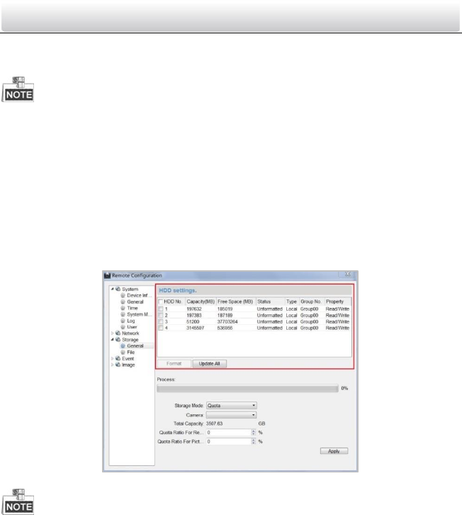
9.4.2 Formatting the HDDs
The HDDs of the storage server need to be formatted for the captured picture storage.
Steps:
1. Select the added storage server from the list and click Remote Config.
2. Click Storage->General to enter the HDD Formatting interface.
3. Select the HDD from the list and click Format. You can check the formatting process
from the process bar and the status of the formatted HDD changes from
Unformatted to Normal Status.
Figure 9-6 Remote Configuration Interface of Storage Server
Formatting the HDDs is to pre-allocate the disk space for storage and the original data of
the formatted HDDs will not be deleted.
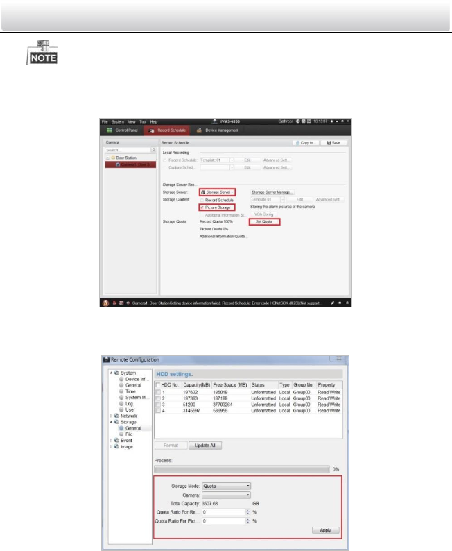
9.4.3 Configuring Storage Server Picture Storage
Before you start:
The storage server needs to be added to the client software and the HDDs need to be
formatted for the captured pictures storage.
Steps:
1. Open the Record Schedule page.
2. Select the camera from the Camera Group list.
3. Select the storage server from the Storage Server drop-down list.
Video Intercom Door Station·User Manual
59
You can click Storage Server Management to add, edit or delete the storage server.
4. Check the checkbox of Picture Storage to store the alarm pictures of the camera
when event occurs.
Figure 9-7 Record Schedule Settings
5. Click Set Quota to enter the HDD management interface of the storage server. You
can set the corresponding quota ratio for captured picture information.
Figure 9-8 Storage Settings
Example: If you set the picture quota as 60%, then the 60% of the storage space
can be used for storing the captured pictures.
6. Click Save to save the settings.
9.5 Group Management
Purpose:
Video Intercom Door Station·User Manual
60
You can add groups to community, outer door station, or other, and assign devices to
each group.
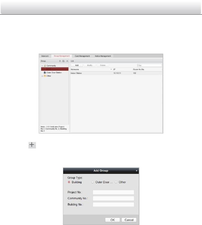
9.5.1 Adding Group
1. Click the Group Management tab to enter the group management interface.
Figure 9-9 Group Management Interface
2. Click the button on the right group list to pop-up group adding dialog box.
3. Select a kind of group type.
Selecting Building as Group Type
Figure 9-10 Group Adding Interface (Building)
1) Check the checkbox of building.
2) Enter the project No., community No., and building No..
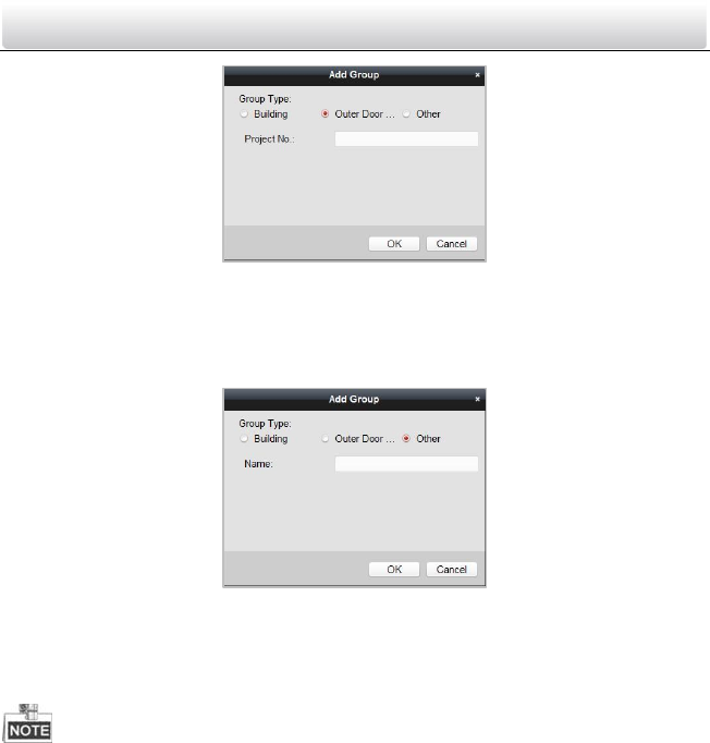
Selecting Outer Door Station as Group Type
Video Intercom Door Station·User Manual
61
Figure 9-11 Group Adding Interface (Outer Door Station)
1) Check the checkbox of outer door station.
2) Enter the project No..
Selecting Other as Group Type
Figure 9-12 Group Adding Interface (Other)
1) Check the checkbox of other.
2) Enter the name.
4. Click the OK button to complete the group adding settings.
Groups that have been successfully added will be automatically listed in the group list
according to different group types.
You can add group to Other Group and set different groups to assign cards to staff
other than residents, such as administrator, security guard and cleaning staff, etc.,. So
you can assign corresponding cards and configure their different permissions.
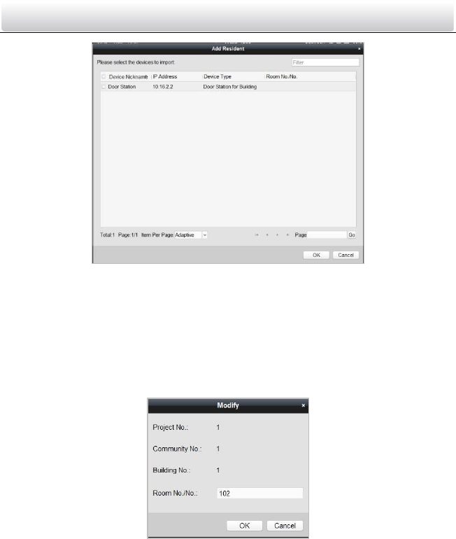
9.5.2 Assigning Devices to Group
1. Click the Add button on the right to enter resident adding interface for adding devices
to the list.
Video Intercom Door Station·User Manual
62
Figure 9-13 Resident Adding Interface
2. Check the checkbox of device and enter the Room No. of indoor stations to assign the
device to the community.
3. Click the OK button to save the settings.
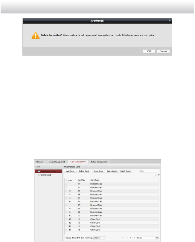
9.5.3 Modifying Device Information
1. Select an added device.
2. Click the Modify button to enter the device modifying interface.
Figure 9-14 Device Modifying Interface
3. Click the OK button to complete the device modifying operation.
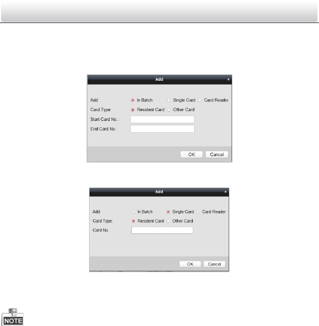
9.5.4 Deleting Device
1. Select an added device.
2. Click the Delete button to pop up a dialog box.
Video Intercom Door Station·User Manual
63
Figure 9-15 Group Deleting Interface
3. Click the OK button to complete the group deleting operation.
9.6 Card Management
Purpose:
You can add unauthorized cards to the community and then you can assign the cards to
the corresponding indoor station and outdoor stations. For example, if there are 3
residents living in Room 401, you can assign 3 cards to No. 401 indoor Station. For each
indoor station, you can assign many cards, and you can assign these cards to the door
station from same building.
Steps:
1. Click the Video Intercom button on the control panel to enter the video intercom
interface.
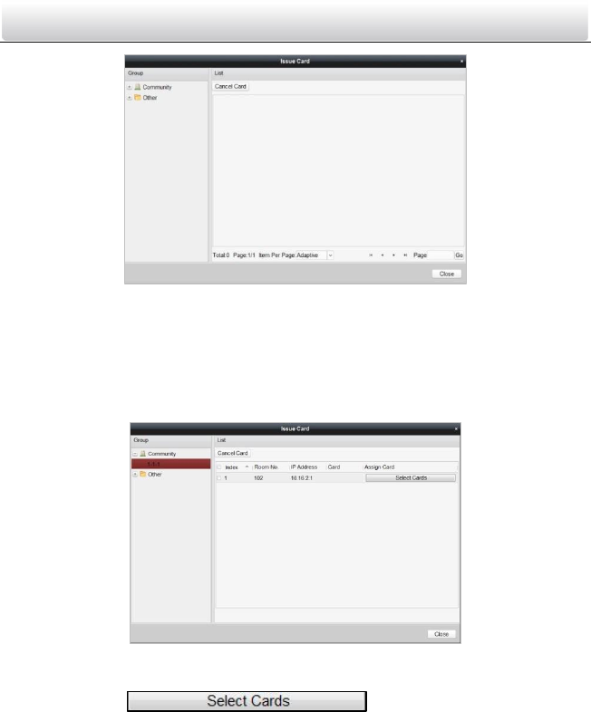
2. Press the Card Management tab to enter the card management interface.
Figure 9-16 Card Management Interface
9.6.1 Unauthorized Card Management
Adding Card
1. Click the Add Card button to pop up card adding dialog box.
Video Intercom Door Station·User Manual
64
2. Select card adding mode: In Batch, By Single, Card Reader.
3. Select card type: Resident Card, Other Card.
4. Enter Start Card No. and End Card No. (adding in batch), or enter card No. (adding by
single or card reader).
Figure 9-17 Adding in Batch
Figure 9-18 Adding by Single or Card Reader
5. Click the OK button to save the settings.
Two card types are recommended. Resident card is used by residents living in the
community, and other card is used by visitors (guest, serviceman, etc.) in the
community.
Issuing Card
1. Click the Issue Card button to pop up card issuing dialog box.
Video Intercom Door Station·User Manual
65
Figure 9-19 Card Issuing Interface
2. Issue Resident Card or Other Card.
Issuing Resident Card
1) Select Community on the left and the indoor stations of the community will be
listed in the resident list.
Figure 9-20 Resident Card Issuing Interface
2) Click the button to pop up card selection
interface for selecting unauthorized cards to be issued to the indoor station.
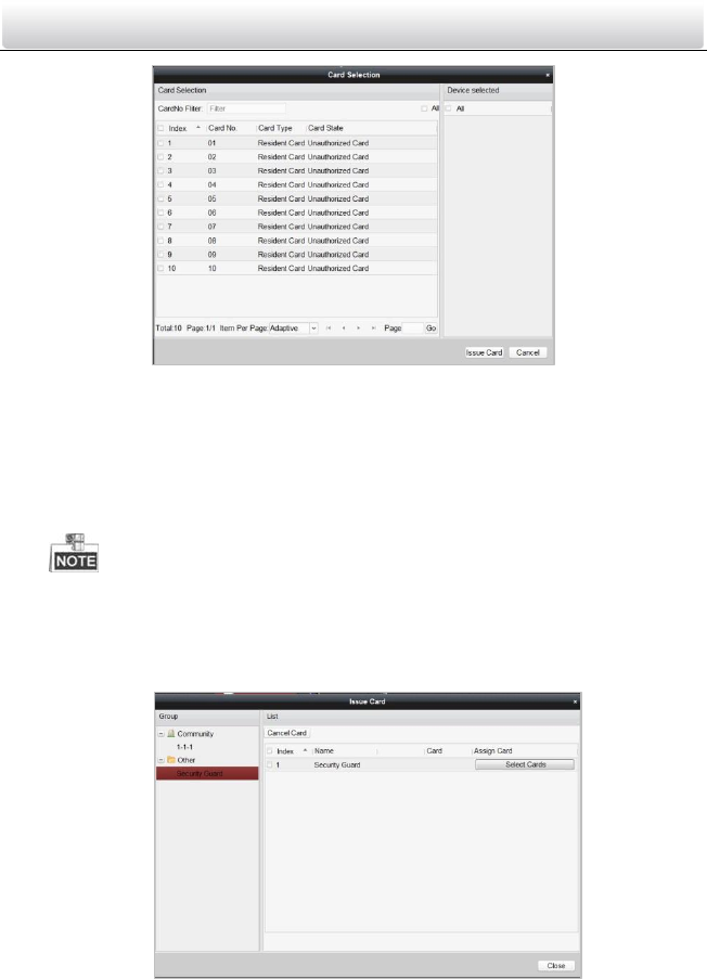
Video Intercom Door Station·User Manual
66
Figure 9-21 Resident Card Selection Interface
3) Check the checkboxes of the cards that need issuing to the indoor station, and
check the checkbox of door stations, doorphones and outer door stations (only
resident cards can be assigned to indoor stations).
4) Click the Issue Card button to complete the resident card issuing settings.
Multiply resident card can be issued to an indoor station.
Issuing Other Card
1) Select Other on the left group list and the name for other card issuing will be
listed in the right list.
Figure 9-22 Other Card Issuing Interface
Video Intercom Door Station·User Manual
67
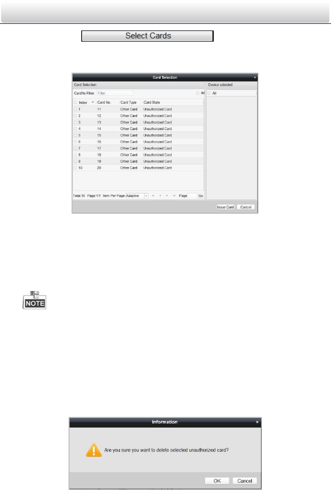
2) Click the button to pop up card
selection interface for selecting unauthorized cards to be issued to the
indoor station.
Figure 9-23 Other Card Selection Interface
3) Check the checkboxes of the cards that need issuing to the indoor station, and
check the checkbox of door stations, doorphones and outer door stations (only
resident cards can be assigned to indoor stations).
4) Click the Issue Card button to complete the other card issuing settings.
Multiply other cards can be issued to a same group.
Deleting Card
Deleting Unauthorized Card
1) On the card management interface (Figure 9-11), check the checkbox(ex) of
unauthorized card(s).
2) Click the Delete Card button to pop up unauthorized card deleting box.
Figure 9-24 Card Deleting Information Box
Video Intercom Door Station·User Manual
68
3) Click the OK button to delete the card(s).
Deleting Issued Card
1) On the resident/other card issuing interface (Figure 9-15, Figure 9-17), select
a community group or an Other group.
2) Click the button to enter the card
selection interface for deleting issued card.
3) Cancel the checkbox(ex) of issued card(s) and check the checkbox door
stations, doorphones or outer door stations.
4) Click the Issue Card button to complete the issued card deleting settings.
You can cancel issued card(s) from single or certain door stations by cancelling
the checkbox(es) from the device list.
To cancel all issued cards, check the checkbox(es) of Room No. / name, and
click the Cancel Card button to cancel all cards issued to the device. The card
state will be reset to unauthorized card.
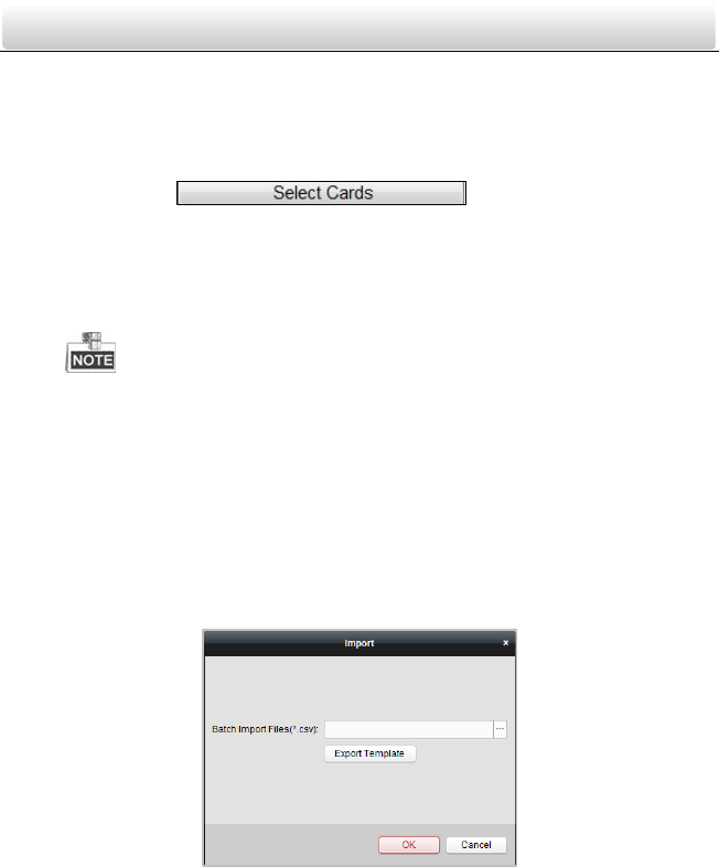
Importing Unauthorized Cards in Batch
1. Click the Batch Import button to pop up card batch importing dialog box.
Figure 9-25 Bath Import Interface
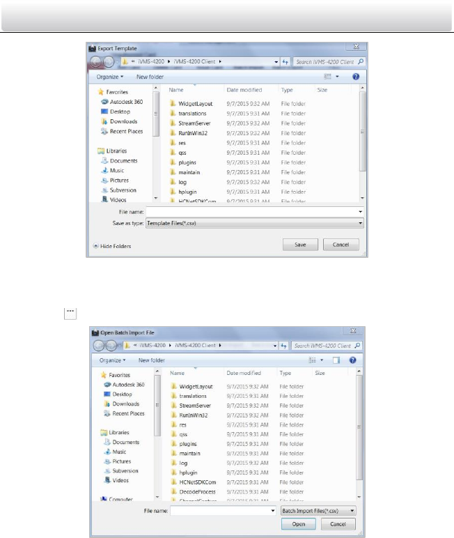
2. Click the Export Template button to export the template of the batch import file.
Video Intercom Door Station·User Manual
69
Figure 9-26 Template File Exporting Interface
3. Fill in the template of the batch import file and click the Save button to save it.
4. Click the button to select the batch import file.
Figure 9-27 Batch Import File Opening Interface
5. Click the Open button.
6. Click the OK button to start importing the batch import file.
Exporting Unauthorized Cards in Batch
1. Click the Batch Export button after adding unauthorized cards.
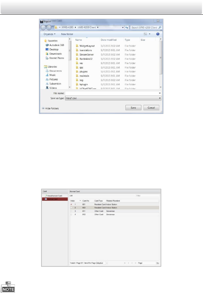
Video Intercom Door Station·User Manual
70
Figure 9-28 Batch Export Interface
2. Select the saving file path and click the Save button.
3. Generate an excel file in the saving directory after exporting unauthorized cards in
batch.
9.6.2 Normal Card Management
On card management interface, click the normal card button to enter the normal card
interface for listing normal cards including resident card and other card. After issuing
cards, the issued cards will be listed in the normal card list, as shown in the figure below.
Figure 9-29 Normal Card Interface
To issue cards with card issuer, please connect the card reader DS-K1F100-D8
(purchased separately) to PC via USB interface. Open iVMS-4200 and enter the
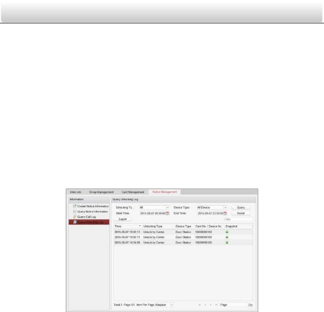
Video Intercom Door Station·User Manual
71
directory of Video Intercom->Card Management->Unauthorized Card->Add Card.
Swipe the unauthorized card in turn and the card No. will be read and added to the
device automatically.
After issuing each card via iVMS-4200, the device plays the voice prompt: Issuing card
finished.
9.7 Notice Management
9.7.1 Querying Unlocking Log
Steps:
1. Click the Query Unlocking Logs button to enter query unlocking logs interface.
2. Select the unlocking type, device type, and set the start time and end time.
Figure 9-30 Query Unlocking Logs
3. Click the Query button to search the unlocking log.
4. Click the Export button to export the unlocking logs.
9.8 Device Arming Control
Steps:
1. Select Tool->Device Arming Control to enter the device arming control interface.
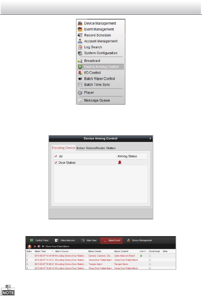
Video Intercom Door Station·User Manual
72
Figure 9-31 Tool Menu
2. Set the arming status of the device as armed, and the alarm information will be auto
uploaded to the client software when alarm occurs
Figure 9-32 Device Arming Control
Figure 9-33 Alarm Events
After adding the device to the client software, it will be armed automatically.
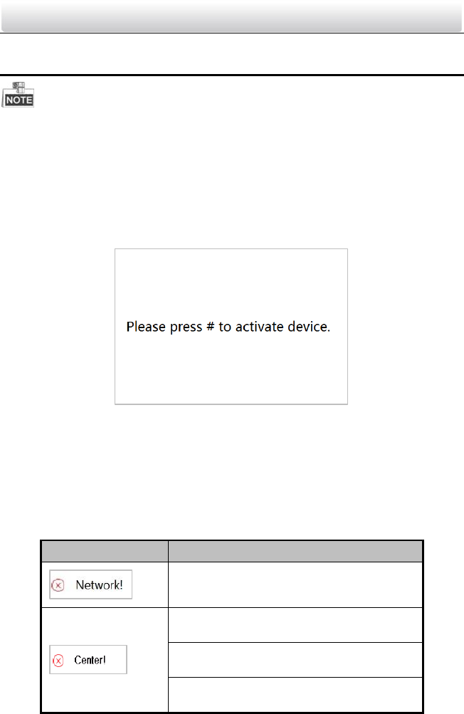
Video Intercom Door Station·User Manual
73
10 Local Operation
The number key 2, 8, 4, 6 as direction keys ▲, ▼ , ◄, ► to turn down, up, left and
right.
The # key works as a confirm key.
The * key works as a delete key.
10.1 Activating the Device
Figure 10-1 Activate the Device
The operation of door station cannot be performed when the device is not activated.
Please activate the device with video intercom device set-up tool, batch configuration
software and iVMS-4200. For detailed information, please refer to Chapter 8 and
Chapter 9.
10.2 Status
Icon
Description
Please check the network cable of the door
station.
Invalid SIP server IP address. Set the SIP
server IP address.
Network of SIP server is not available. Check
the SIP server network connection.
SIP server communication is not available.
Check if the SIP server IP address is correct.
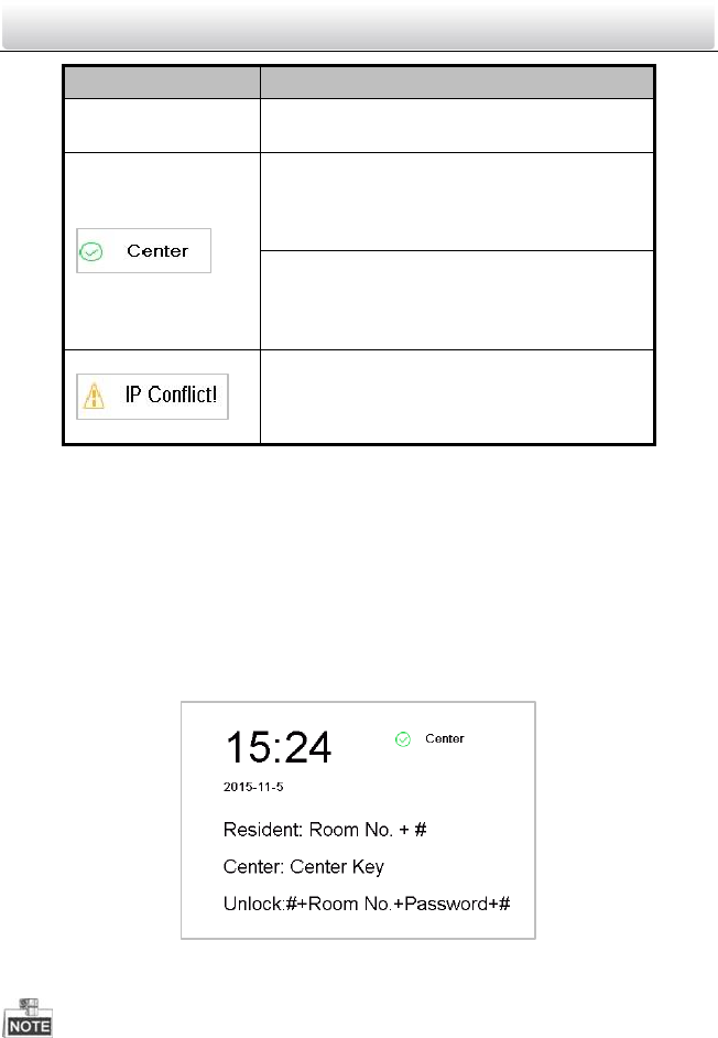
Video Intercom Door Station·User Manual
74
Icon
Description
SIP server rejected to login the device. Check
if the device No. has been registered.
The network connection of the main door
station/outer door station is normal, and the
main door station/outer door station has
been successfully registered to the SIP server.
The network connection of the sub door
station is normal, and the sub door station
has been successfully registered to the main
door station/SIP server.
IP address of the door station conflicts with
other devices’ IP address
10.3 Unlocking Door
10.3.1 Unlocking Door by Password
Purpose:
You can unlock the door by entering the password.
Steps:
1. Enter the main interface of door station.
Figure 10-2 Main Interface of Door Station
2. Enter the # key + Room No. + Password + the # key to unlock the door
The password varies according to different rooms.
The default password is 123456.
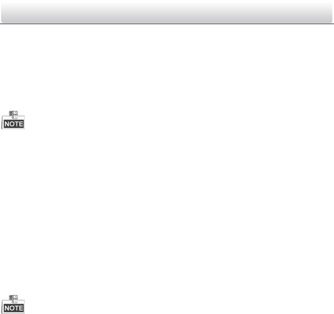
Video Intercom Door Station·User Manual
75
10.3.2 Unlocking Door by Swiping Card
Purpose:
After issuing the cards, you can unlock the door by swiping the assigned card.
Step:
1. Swipe the card on the card induction area.
2. Hear a voice prompt of the device: Door is open.
You cannot open the door by swiping the main card.
10.4 Starting Video Call
Purpose:
You can enter the Room No. of a certain resident to start a video call and unlock the
door by the resident.
10.4.1 Video Call via Main/Sub Door Station
Steps:
1. Enter the main interface of door station
2. Enter the Room No. and click the # key or the Call key.
The resident can receive/decline the video call, unlock the door, call the elevator, etc.
A voice prompt (Please input the correct Room No.) can be heard if the Room No. is
invalid.
10.4.2 Video Call via Outer Door Station
Steps:
1. Enter the main interface of outer door station.
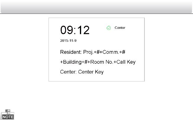
Video Intercom Door Station·User Manual
76
Figure 10-3 Main Interface of Outer Door Station
2. Enter the project No. + the # key + the communication No. + the # key + the building
No. + the # key + the Room No. + the Call key to start a video call of a certain
resident.
The resident can receive/decline the video call, unlock the door, call the elevator, etc.
A voice prompt (Please input the correct Room No.) can be heard if the Room No. is
invalid.
To set the door station as outer door station, you should configure the device type as
outer door station via batch configuration tool or iVMS-4200 client software. For
further details, refer to the user manual in the disk.
10.5 Setting Parameters
Purpose:
You can set the network configuration, local settings, password and volume of the door
station. You can also view the version of the device and issue cards with it.
Steps:
1. Enter the main interface of door station.
2. Long-click the * key and the # key simultaneously for 2 seconds to enter the admin
password interface.
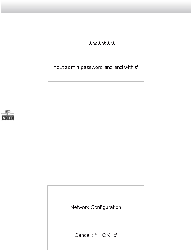
Video Intercom Door Station·User Manual
77
Figure 10-4 Admin Password Interface
3. Enter the admin password and end with the # key to enter the settings interface.
4. Click the left/right direction key (number key 4 and number key 6) to realize the
change among different settings interfaces.
The default admin password is 888999.
10.5.1 Network Configuration
Purpose:
You can set the network parameters of the door station.
Steps:
1. Enter the admin password to enter the settings interface.
2. Press number key 4 and 6 to switch to the network configuration interface.
Figure 10-5 Network Configuration Interface
3. Press the # key to enter the network parameters settings interface.
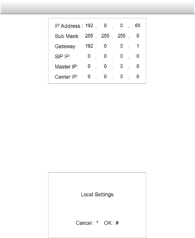
Video Intercom Door Station·User Manual
78
Figure 10-6 Network Parameters Settings Interface
4. Move the cursor to parameters to be configured.
5. Press the # key to enter/exit the editing mode.
6. Press the * key to exit the network configuration interface after accomplishing
network parameters settings.
10.5.2 Local Settings
Purpose:
You can set the numbers of the door station.
Steps:
1. Enter the admin password to enter the settings interface.
2. Press number key 4 and 6 to switch to the local settings interface.
Figure 10-7 Local Settings Interface
3. Press the # key to enter the local parameters settings interface.
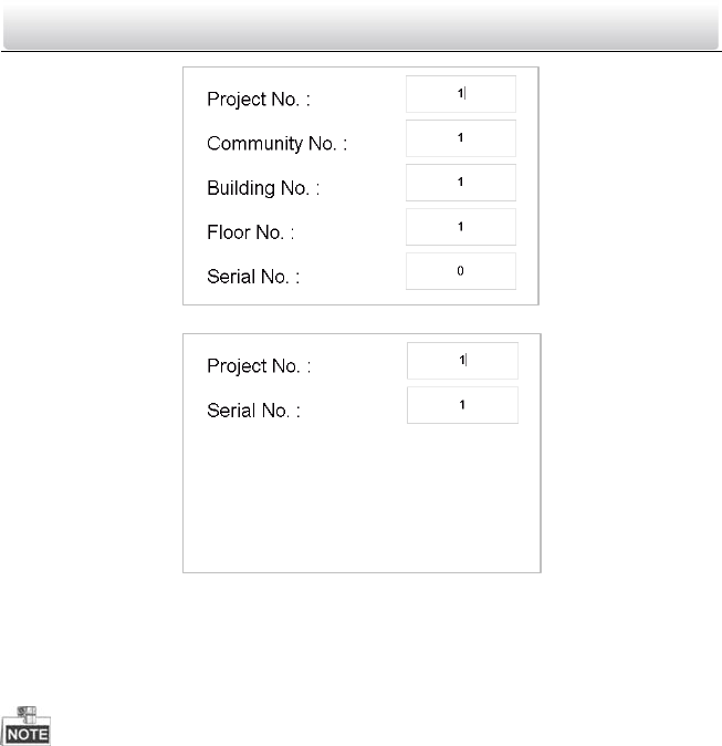
Video Intercom Door Station·User Manual
79
Figure 10-8 Local Parameters Settings Interface (Main/Sub Door Station)
Figure 10-9 Local Parameters Settings Interface (Outer Door Station)
4. Move the cursor to parameters to be configured.
5. Press the # key to enter/exit the editing mode.
6. Press the * key to exit the local settings interface after accomplishing local parameters
settings.
In the main/sub door station mode, the serial No. of main door station should be set
as 0, and the serial No. of sub door station should be larger than 0.
For each main door station, at most 8 sub door stations can be installed.
For the outer door station, the serial No. cannot be set as 0.
10.5.3 Issuing Card
Purpose:
You can issue cards with the door station.
Steps:
1. Enter the admin password to enter the settings interface.
2. Press number key 4 and 6 to switch to the card issuing interface.
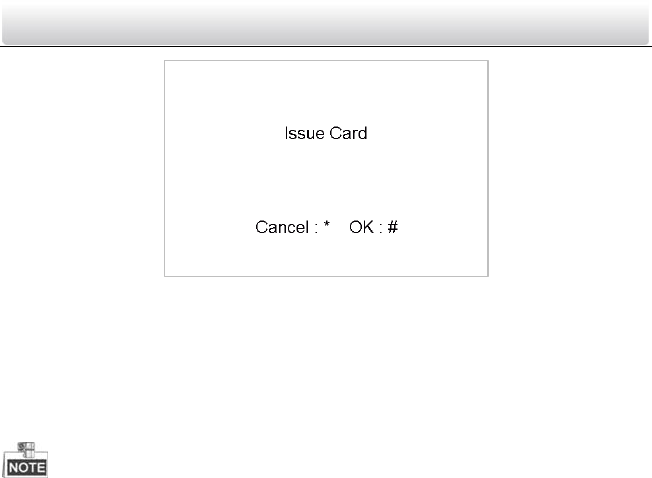
Video Intercom Door Station·User Manual
80
Figure 10-10 Card Issuing Interface
3. Press the # key to enter the main card swiping interface.
4. Swipe the main card in the card induction area, and it produces a voice prompt:
Issuing card succeeded.
5. Swipe the unauthorized sub cards in turn after hearing a voice prompt: Please swipe
the sub card.
6. Press the * key to exit the card issuing interface.
If the main card is invalid, it prompts the message: Incorrect Main Card.
For the door station (D series), if the amount of sub cards exceeds 2500, no more sub
card can be issued and the station prompts the message: No more sub card can be
issued.
For the outer door station, if the amount of sub cards exceeds 50000, no more sub
card can be issued and the station prompts the message: No more sub card can be
issued.
After enrolling cards with client software, the card issuing function will be disabled on
the user interface.
10.5.4 Changing Password
Purpose:
You can change the admin password of the door station.
Steps:
1. Enter the admin password to enter the settings interface.
2. Press number key 4 and 6 to switch to the password settings interface.
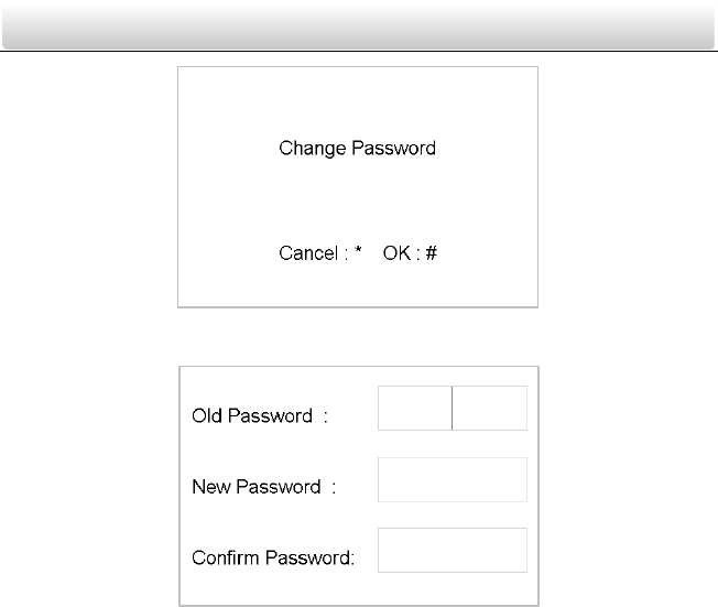
Video Intercom Door Station·User Manual
81
Figure 10-11 Password Settings Interface
3. Press the # key to enter the local parameters changing interface.
Figure 10-12 Password Changing Interface
4. Move the cursor to the old password textbox.
5. Press the # key to enter/exit the editing mode, and enter the old password.
6. Move the cursor to the new password textbox.
7. Press the # key to enter/exit the editing mode, and enter a new password.
8. Move the cursor to the confirm textbox.
9. Press the # key to enter/exit the editing mode, and enter a new password again.
10. Move the cursor to parameters to be configured.
11. Press the # key to enter/exit the editing mode.
12. Press the * key to exit the password changing interface.
10.5.5 Volume Settings
Purpose:
You can adjust the volume of the door station.
Steps:
1. Enter the admin password to enter the settings interface.
2. Press number key 4 and 6 to switch to the volume settings interface.
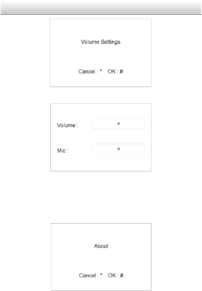
Video Intercom Door Station·User Manual
82
Figure 10-13 Volume Settings Interface
3. Press the # key to enter the volume parameters settings interface.
Figure 10-14 Volume Parameters Settings Interface
4. Press the # key + numeric key + the # key to edit the value of volume.
5. Press the * key to exit the volume settings interface.
10.5.6 About
On the settings interface, press number key 4 and 6 to switch to the About interface,
and press the # key to view the version of the device.
Figure 10-15 Device Version Interface
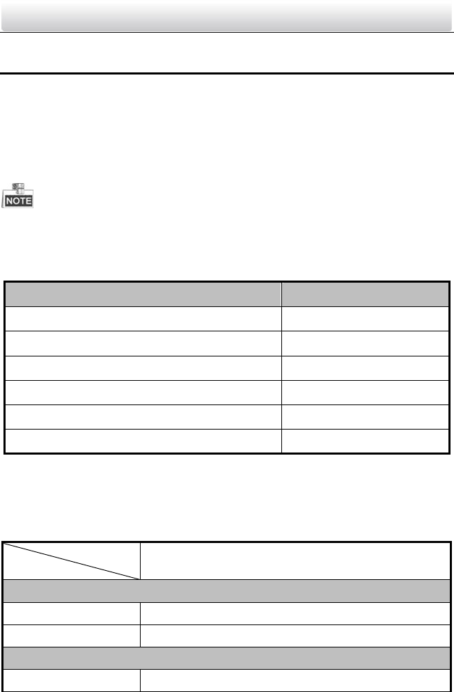
Video Intercom Door Station·User Manual
83
Appendix
Installation Notice
While installing the indoor station, make sure that the distance between any two
devices is far enough to avoid the howling and echo. The distance between two devices
is recommended to be longer than 10 meters.
Here devices refer to indoor station, outdoor station and master station.
Wiring Cables
Cable
Specification
Power Cord of Door Station
RVV 2*1.0
Network Cable of Door Station
UTP-five Categories
Door Lock Wiring (With Door Magnetic)
RVV 4*1.0
Door Lock Wiring (Without Door Magnetic)
RVV 2*1.0
Exit Button Wiring
RVV 2*0.5
External Card Reader Wiring
RVVP 4*0.75
Specification
Specification of DS-KD8102-V
Model
Parameters
DS-KD8102-V
System Parameters
Processor
High-Performance Embedded SOC Processor
Operation System
Embedded Linux Operation System
Video Parameters
Camera
CMOS Low Illumination 1.3 MP HD Colorful Camera
Video Intercom Door Station·User Manual
84
Model
Parameters
DS-KD8102-V
Video Compression
Standards
H.264
Resolution
1280 × 720
Video Standard
PAL: 25 fps, NTSC: 30 fps
Display Parameters
Display Screen
3.5-Inch Colorful TFT LCD
Resolution
480 × 320
Operation Method
Capacitive Touch Keypad
Operation Interface
LCD Display, Easy Menu
Audio Parameters
Audio Input
Built-in Omnidirectional Microphone
Audio Output
Built-in Loudspeaker
Audio Compression
Standard
G.711 U
Audio Compression
Rate
64 Kbps
Audio Quality
Noise Suppression and Echo Cancellation
Access Control Parameters
Internal Card Reader
Built-in IC Card Reader
External Card Reader
Wiegand 26, Wiegand 34, or RS485 IC Reader
Door Magnetic
Detection
Detect Door Magnetic Status
IR Detection
Approaching
Detection
Support IR Detection, Vertical Distance: from 60 cm
to 80 cm
Light Supplement
Light Supplement
Mode
Visible Light Supplement
Network Parameters
Ethernet
10/100 Mbps Self-Adaptive Ethernet
Video Intercom Door Station·User Manual
85
Model
Parameters
DS-KD8102-V
Network Protocol
TCP/IP, SNMP, SIP, RTSP
Alarm Parameters
Alarm Input
Door Magnetic Alarm, Tamper Alarm
Device Interfaces
Internet Access
1 RJ-45 10/100 Mbps Self-Adaptive Ethernet
Interface
RS-485
1 RS-485 Half-Duplex Port
I/O Input
8
I/O Output
4
Wiegand
1 Wiegand Port for Accessing Wiegand IC Card
Reader
USB
1 USB 2.0, Supporting U-disk
Other Parameters
Material
Plastic
Power Supply
DC 12V
Power Consumption
≤15 W
Working
Temperature
-40° C to + 70° C (-40° F to 158° F)
Working Humidity
10% to 90%
Dimension
418 mm × 145 mm × 61 mm (16.5" × 5.7" × 2.4")
Certification
FCC, IC, CE, C-TICK, ROHS, REACH, WEEE
Specification of DS-KD8002-VM
Model
Parameters
DS-KD8002-VM
System Parameters
Processor
High-Performance Embedded SOC Processor
Operation System
Embedded Linux Operation System
Video Parameters
Video Intercom Door Station·User Manual
86
Camera
CMOS Low Illumination 1.3 MP HD Colorful Camera
Video Compression
Standards
H.264
Resolution
1280 × 720
Video Standard
PAL: 25 fps, NTSC: 30 fps
Display Parameters
Display Screen
3.5-Inch Colorful TFT LCD
Resolution
480 × 320
Operation Method
Physical Touch Keypad
Operation Interface
LCD Display, Easy Menu
Audio Parameters
Audio Input
Built-in Omnidirectional Microphone
Audio Output
Built-in Loudspeaker
Audio Compression
Standard
G.711 U
Audio Compression
Rate
64 Kbps
Audio Quality
Noise Suppression and Echo Cancellation
Access Control Parameters
Internal Card Reader
Built-in IC Card Reader
External Card Reader
Wiegand 26, Wiegand 34, or RS485 IC Reader
Door Magnetic
Detection
Detect Door Magnetic Status
Light Supplement
Light Supplement
Mode
Visible Light Supplement
Network Parameters
Ethernet
10/100 Mbps Self-Adaptive Ethernet
Network Protocol
TCP/IP, SNMP, SIP, RTSP
Alarm Parameters
Alarm Input
Door Magnetic Alarm, Tamper Alarm
Video Intercom Door Station·User Manual
87
Device Interfaces
Internet Interface
1 RJ-45 10/100 Mbps Self-Adaptive Ethernet
Interface
RS-485
1 RS-485 Half-Duplex Port
I/O Input
8
I/O Output
4
Wiegand
1 Wiegand Port for Accessing Wiegand IC Card
Reader
USB
1 USB 2.0, Supporting U-disk
Other Parameters
Material
Aluminum Alloy
Power Supply
DC 12V
Power Consumption
≤15 W
Working
Temperature
-40° C to +70° C (-40° F to 158° F)
Working Humidity
10% to 90%
Protection Level
IP65
Dimension
418 mm × 145 mm × 61 mm (16.5" × 5.7" × 2.4")
Certification
FCC, IC, CE, C-TICK, ROHS, REACH, WEEE
Specification of DS-KD6002-VM
Model
Parameters
DS-KD6002-VM
System Parameters
Processor
High-Performance Embedded SOC Processor
Operation System
Embedded Linux Operation System
Video Parameters
Camera
CMOS Low Illumination 1.3 MP HD Colorful Camera
Video Compression
Standards
H.264
Resolution
1280 × 720
Video Intercom Door Station·User Manual
88
Video Standard
PAL: 25 fps, NTSC: 30 fps
Display Parameters
Display Screen
3.5-Inch Colorful TFT LCD
Resolution
480 × 320
Operation Method
Physical Touch Keypad
Operation Interface
LCD Display, Easy Menu
Audio Parameters
Audio Input
Built-in Omnidirectional Microphone
Audio Output
Built-in Loudspeaker
Audio Compression
Standard
G.711 U
Audio Compression
Rate
64 Kbps
Audio Quality
Noise Suppression and Echo Cancellation
Access Control Parameters
Internal Card Reader
Built-in IC Card Reader
External Card Reader
Wiegand 26, Wiegand 34, or RS-485 IC Reader
Door Magnetic
Detection
Detect Door Magnetic Status
Light Supplement
Light Supplement
Mode
Visible Light Supplement
Network Parameters
Ethernet
10/100 Mbps Self-Adaptive Ethernet
Network Protocol
TCP/IP, SNMP, SIP, RTSP
Alarm Parameters
Alarm Input
Door Magnetic Alarm, Tamper Alarm
Device Interfaces
Internet Interface
1 RJ-45 10/100 Mbps Self-Adaptive Ethernet
Interface
RS-485
1 RS-485 Half-Duplex Port
Video Intercom Door Station·User Manual
89
I/O Input
4
I/O Output
4
Wiegand
1 Wiegand Port for Accessing Wiegand IC Card
Reader
USB
1 USB 2.0, Supporting U-disk
Other Parameters
Material
Aluminum Alloy
Power Supply
DC 12V
Power Consumption
≤15 W
Working
Temperature
-40° C to +70° C (-40° F to 158° F)
Working Humidity
10% to 90%
Protection Level
IP65
Dimension
357 mm × 124 mm × 55 mm (14.1" × 4.9" × 2.2")
Certification
FCC, IC, CE, C-TICK, ROHS, REACH, WEEE

Video Intercom Door Station·User Manual
90