Hangzhou Hikvision Digital Technology MI9605 Mobile NVR User Manual
Hangzhou Hikvision Digital Technology Co., Ltd. Mobile NVR Users Manual
UserManual.wiki
>
Hangzhou Hikvision Digital Technology
>
MI9605 User Manual
Users Manual
Navigation menu
Upload a User Manual
Namespaces
Wiki Guide
HTML
PDF
Info
Views
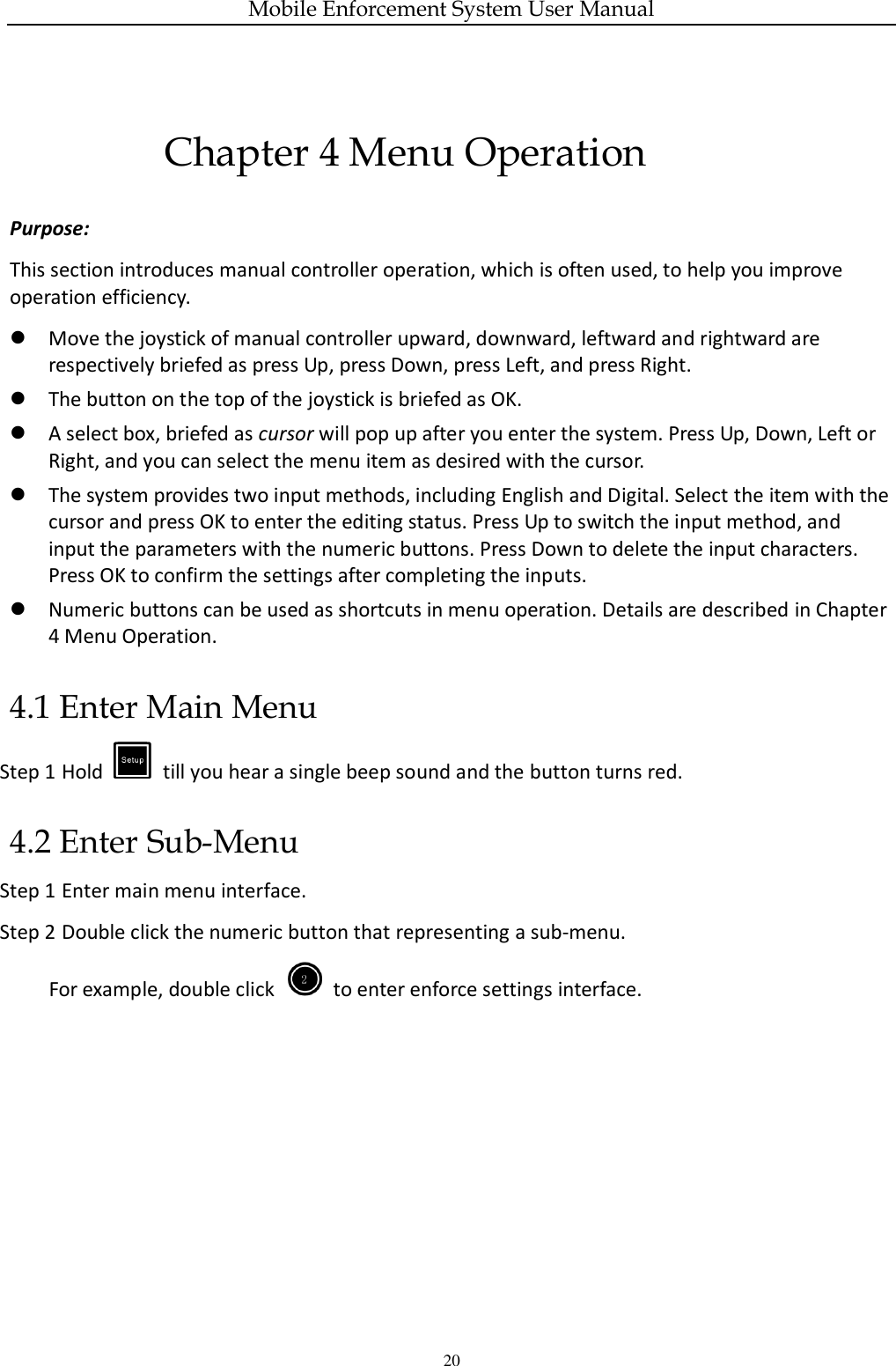
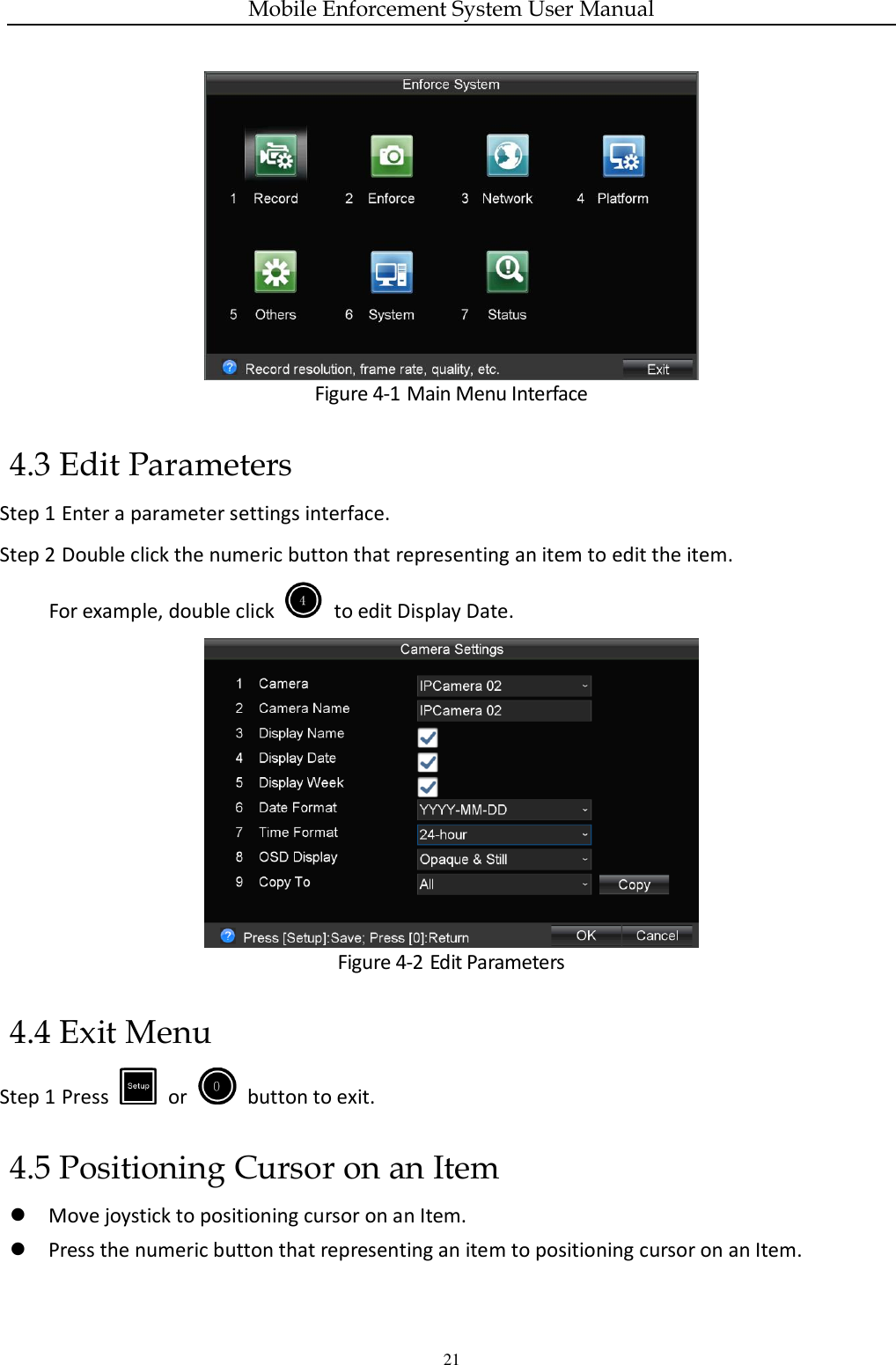
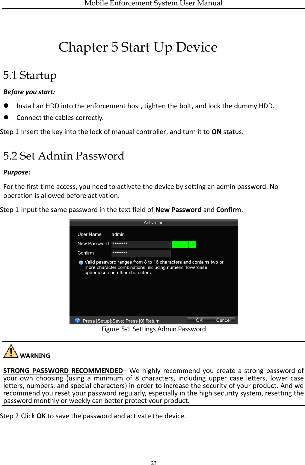
User Manual
Discussion / Help
Navigation

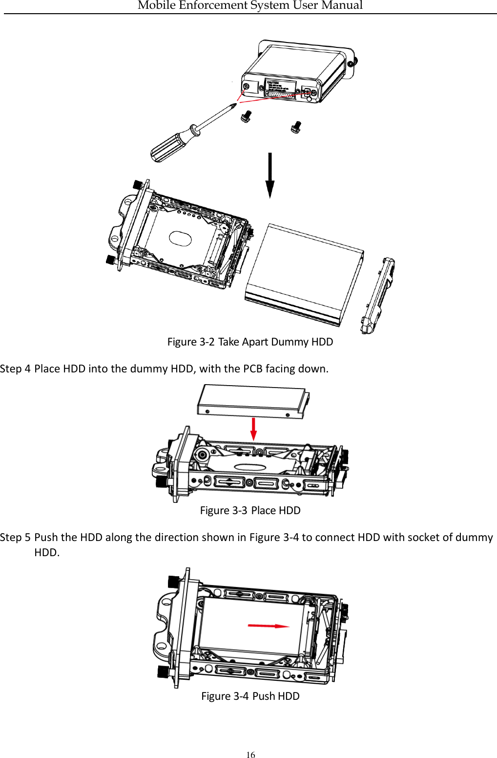
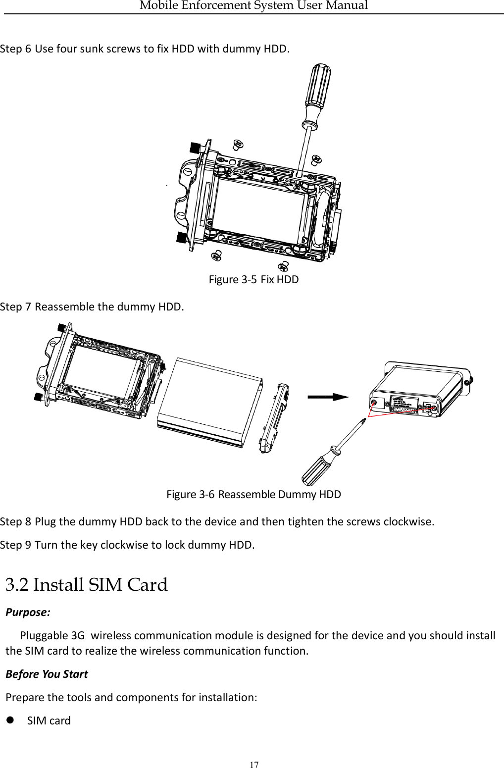
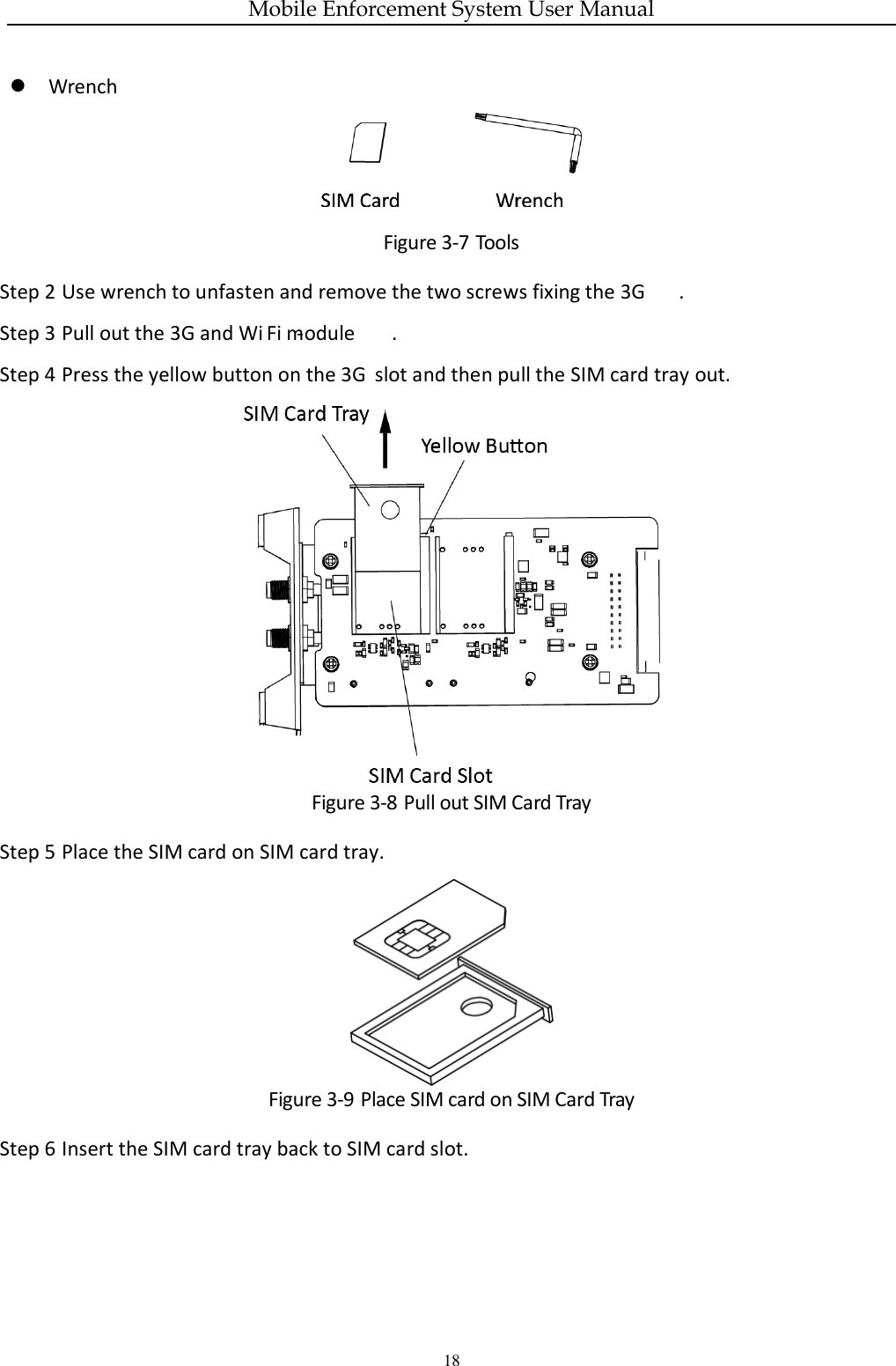
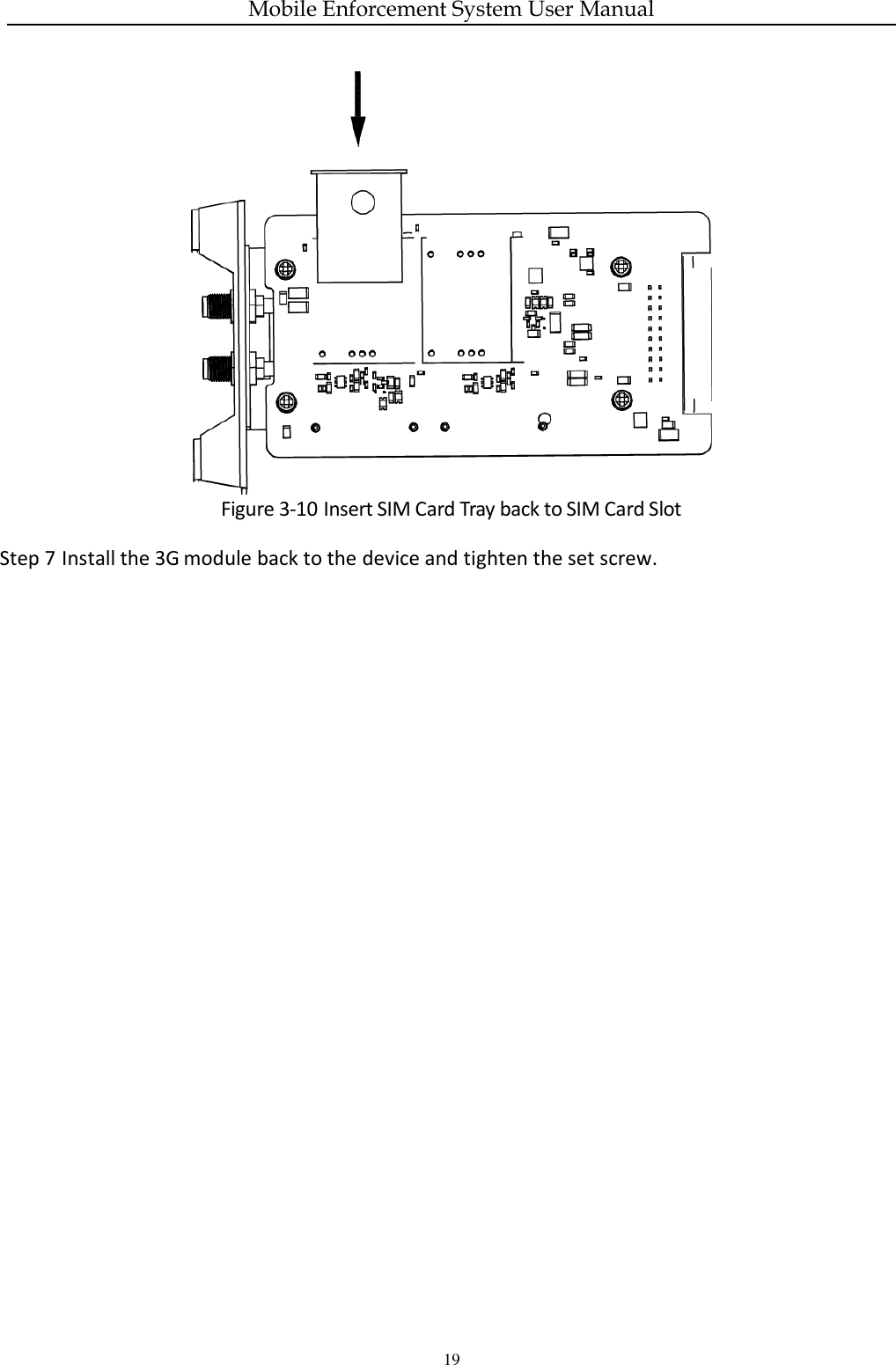

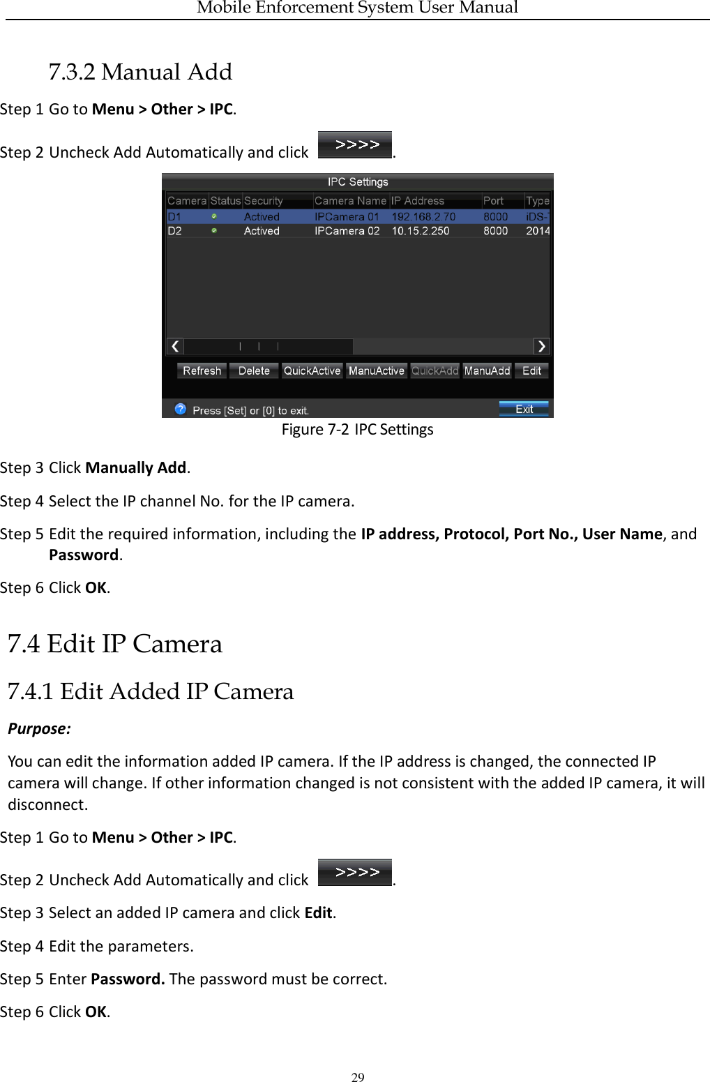
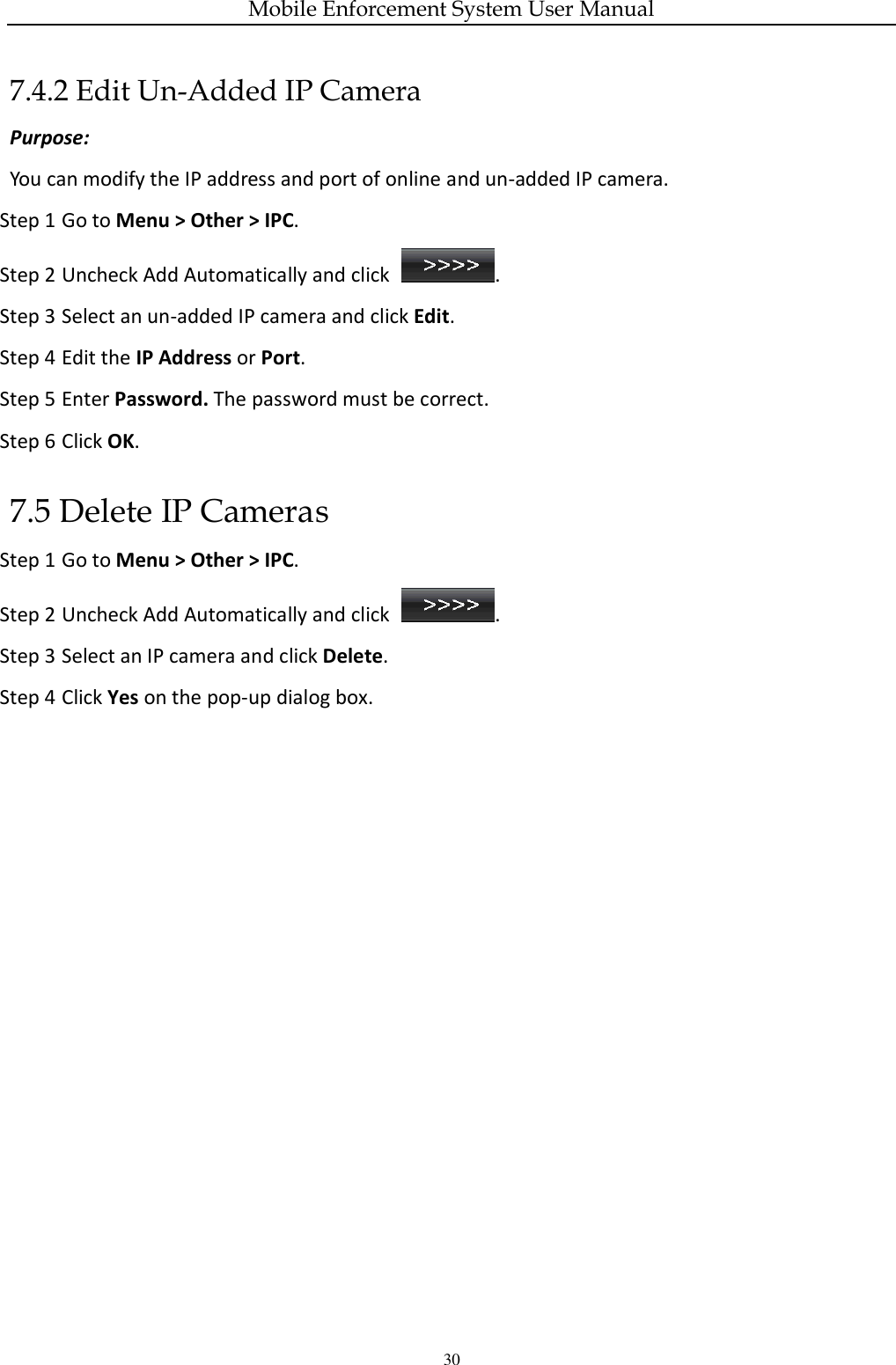
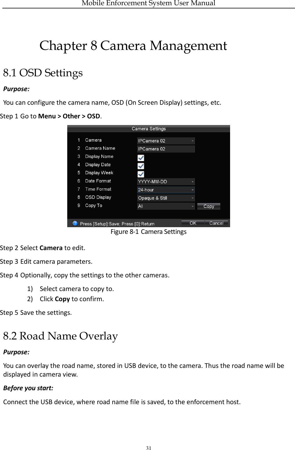
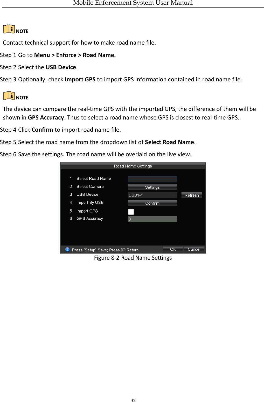
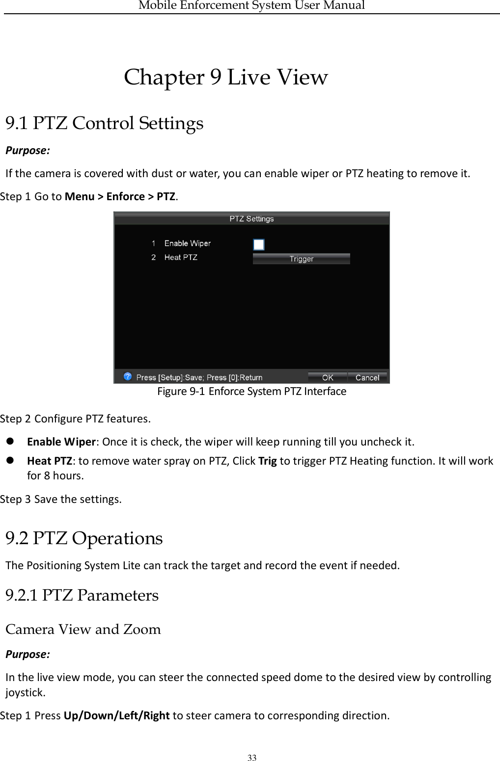
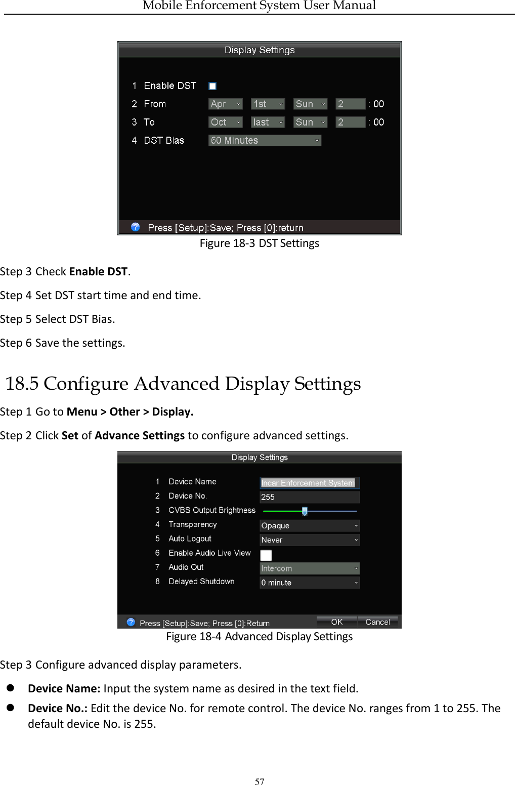
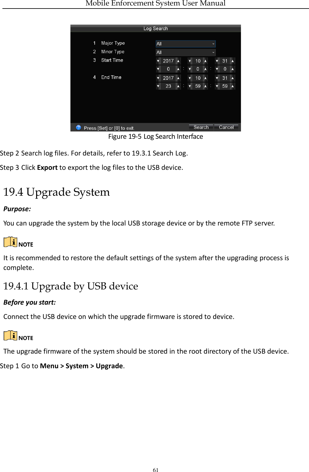
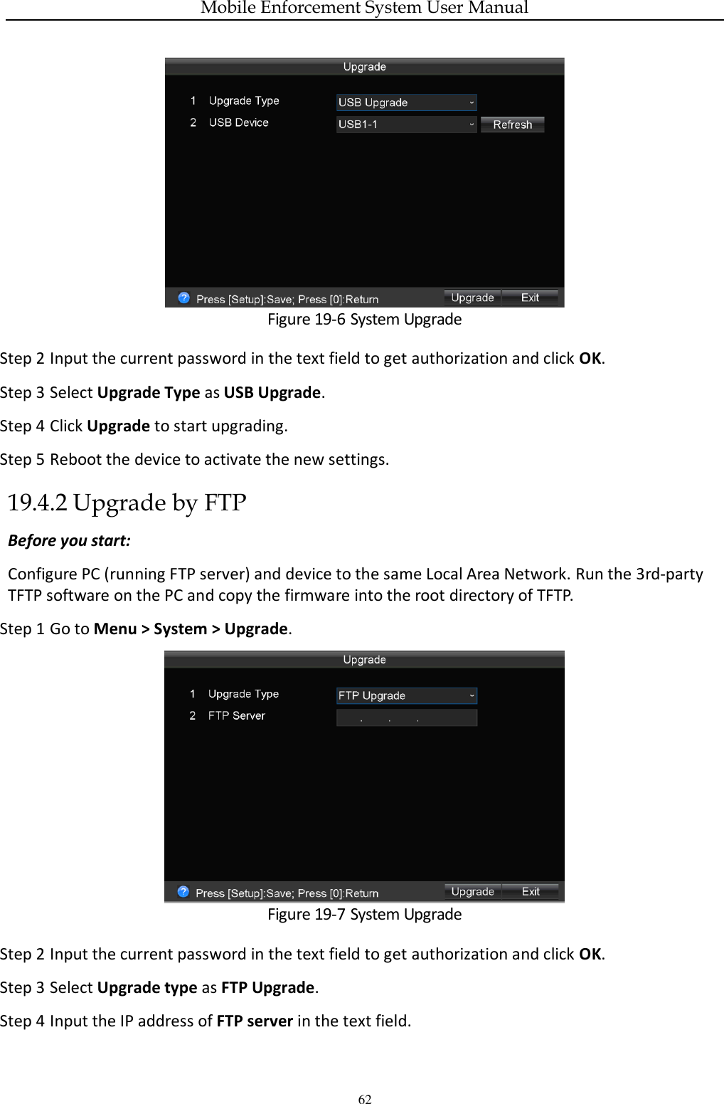
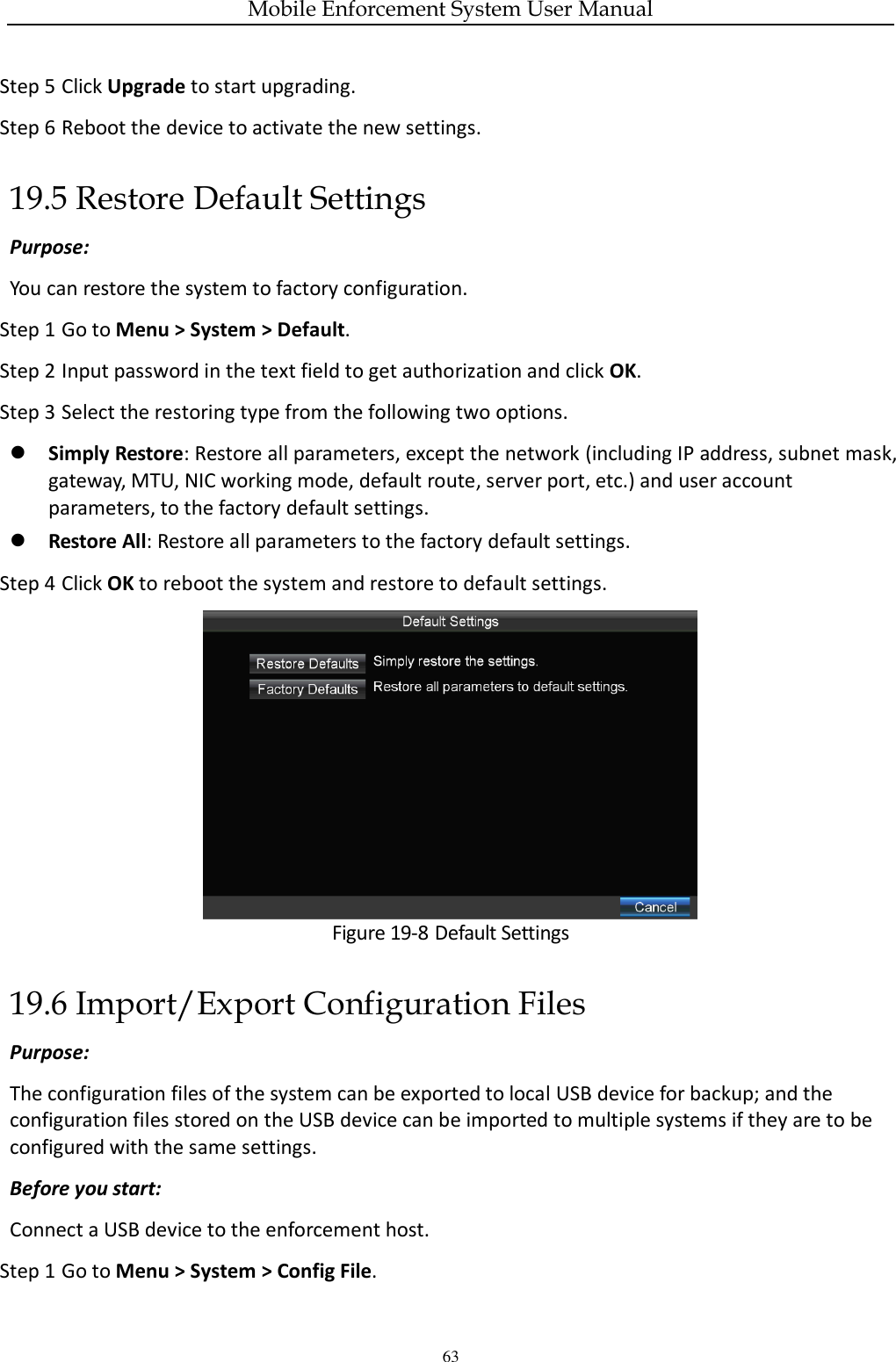
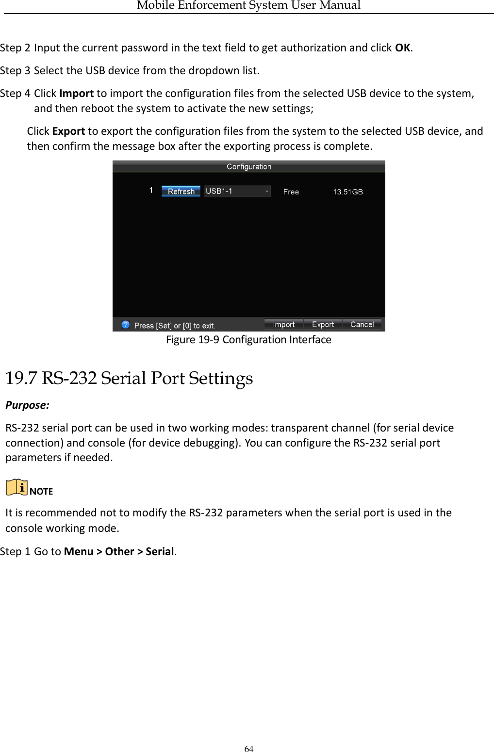
![Mobile Enforcement System User Manual 56 Step 3 Upload Interval(s): GPS positioning information will be uploaded to platform regularly. Invalid range: [1, 999]. 18.3 Configure Basic Display Settings Purpose: You can set the system time, enable the password, etc. Step 1 Go to Menu > Other > Display. The system language is set as English by default, and is not editable. Figure 18-2 Display Settings Step 2 Configure System Time and Enable Password. Check Enable Password to enable password authentication before operations. Step 3 Save the settings. 18.4 Configure DST Settings Step 1 Go to Menu > Other > Display. Step 2 Click Set of DST Settings (Daylight Saving Time).](https://usermanual.wiki/Hangzhou-Hikvision-Digital-Technology/MI9605/User-Guide-4005476-Page-58.png)