Hangzhou Hikvision Digital Technology T03C2N00 Network Camera User Manual
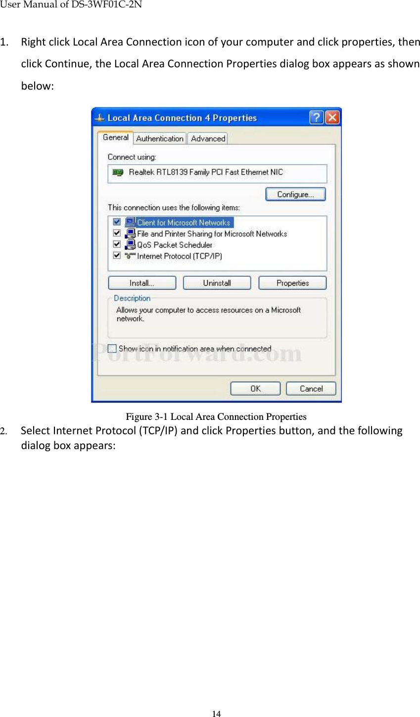
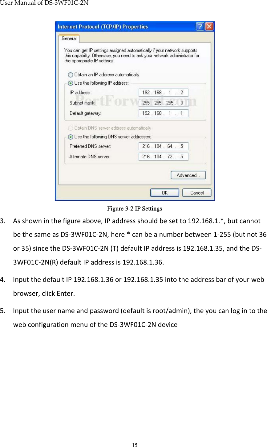
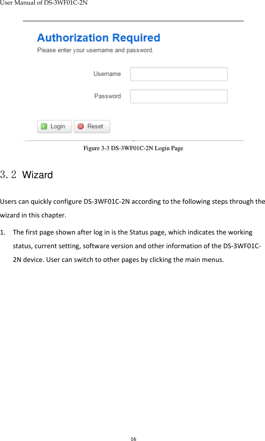
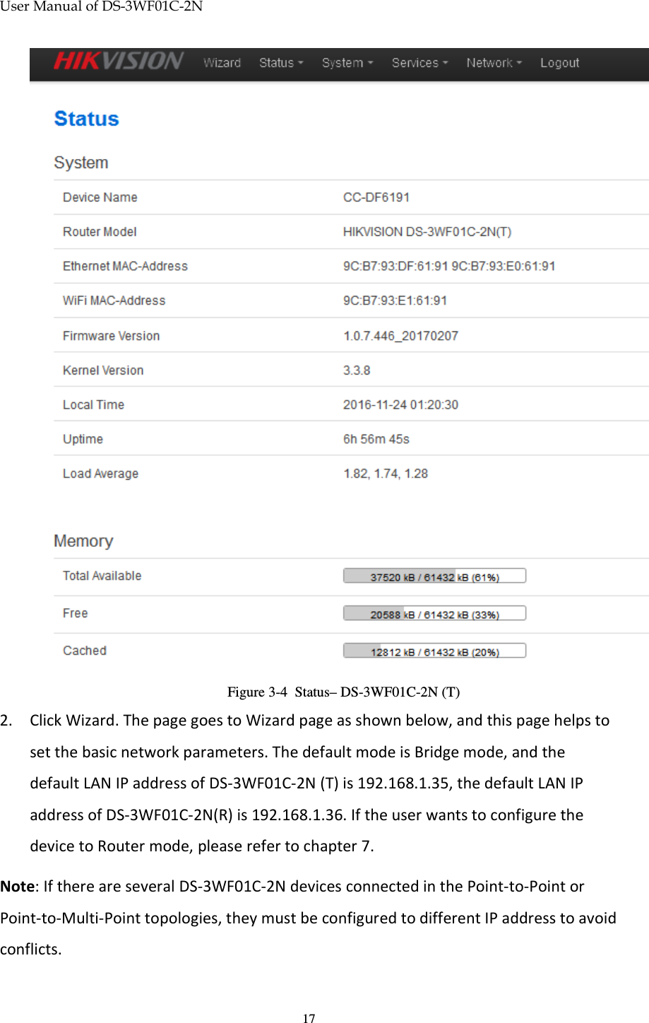
Hangzhou Hikvision Digital Technology Co., Ltd. Network Camera Users Manual
UserManual.wiki
>
Hangzhou Hikvision Digital Technology
>
T03C2N00 User Manual
Users Manual
Navigation menu
Upload a User Manual
Namespaces
Wiki Guide
HTML
PDF
Info
Views
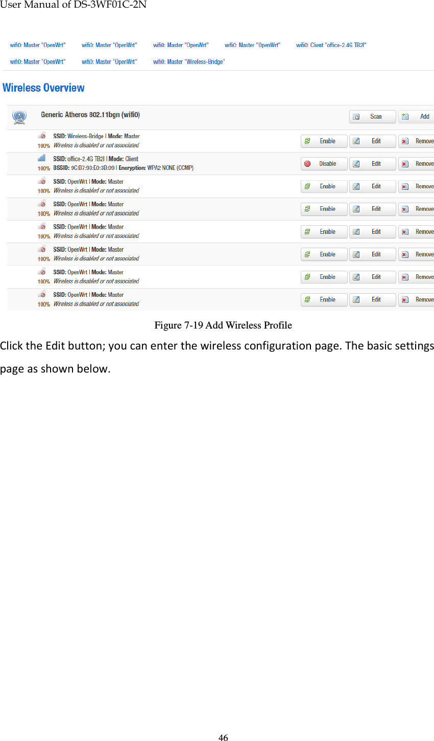
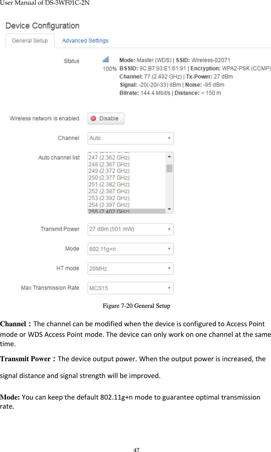
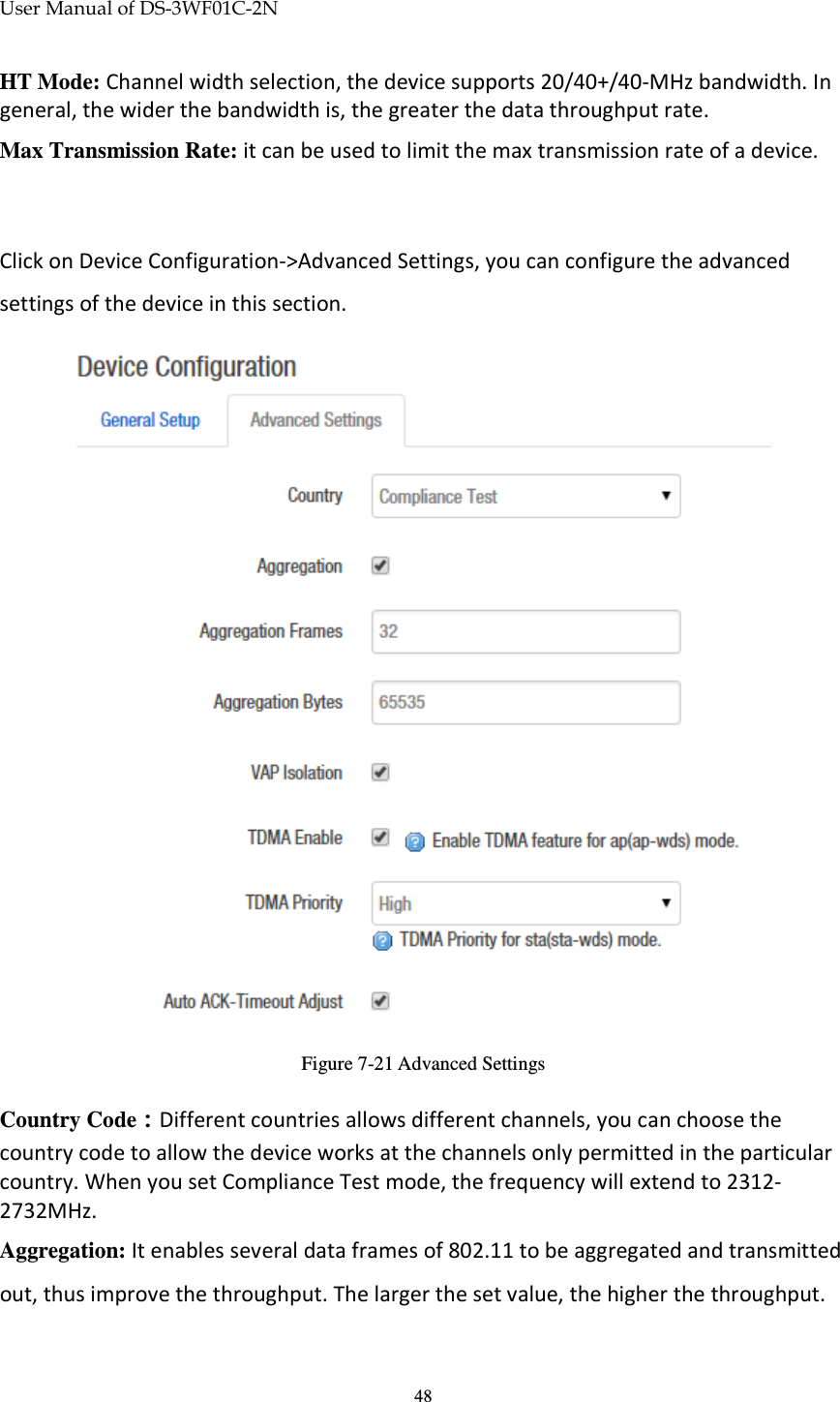
User Manual
Discussion / Help
Navigation