Hangzhou Tuya Information Technology TYLC3 BLE Module User Manual TYLC3 V1 0 0 EN datasheetx
Hangzhou Tuya Information Technology Co.,Ltd BLE Module TYLC3 V1 0 0 EN datasheetx
User Manual
TYLC3&DATASHEET&
Tuya Smart BLE Module
1. Product Overview
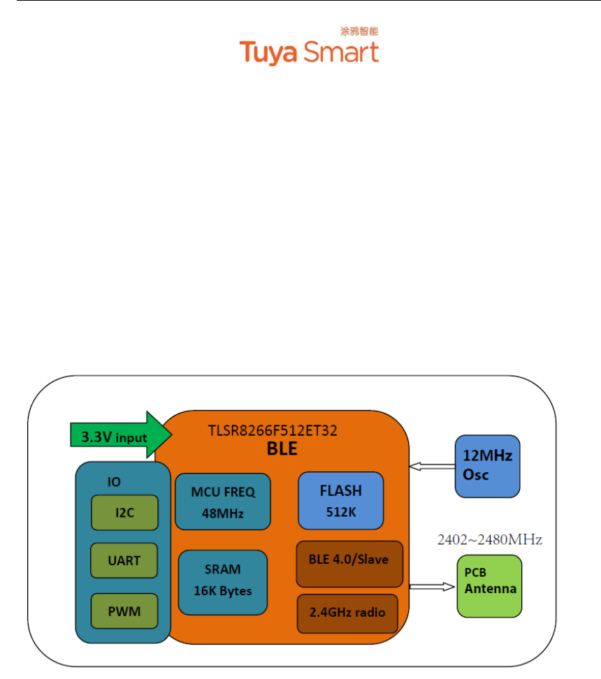
TYLC3 is a Bluetooth (BLE) module designed by HangZhou Tuya Technology Corporation,
which is designed for outputting LED control signals. The BLE Module consists of a highly
integrated wireless Bluetooth chip TLSR8266F512ET32 and some extra electric circuits that have
been programed with Bluetooth network protocol and plenty of software examples. TYLC3
include a 32-bit CPU, BLE, 512K byte flash, 16k SRAM and 4-channel PWM.
Users can customize their LED products by using these PWM signals.
Figure 1 shows the block diagram of the TYLC3.
Figure 1. The block diagram of the TYLC3
1.1 Features
² Integrated low power consumption 32-bit CPU, also known as application processor
² Basic frequency of the CPU can support 48 MHz
² Supply voltage range: 1.9V to 3.6V
² Peripherals: 4*PWM
² BLE RF features:
l Compatible with BLE 4.0
l Transmitting data rate can go up to 1Mbps
l TX transmitting power: +7dBm
l RX receiving sensitivity: -92dBm
l AES hardware encryption
l On-board PCB antenna
Bytes

TYLC3&DATASHEET&
l Operating temperature range: -20℃ to 85℃
1.2 Main Application Fields
² Intelligent LED
² Intelligent household applications
TYLC3&DATASHEET&
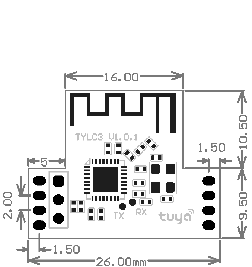
2. Dimensions and Footprint
2.1 Dimensions
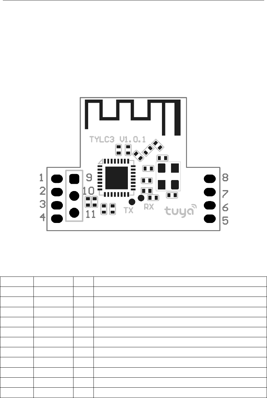
TYLC3 has 2 columns of Pins. The distance between each Pin is 2.0mm.
Size of TYLC3: 20mm(W)*26mm(L).
Figure 2 shows the dimensions of TYLC3.
Figure 2. The dimensions of TYLC3
2.2 Pin Definition
Table 1 shows the general pin attributes of TYLC3
Table 1. The typical pin definition of TYLC3
PIN&NO.&NAME&TYPE&DESCRIPTION&
1& NC& /& Non-connected&
2& NC& /& Non-connected&
3& 3.3V& P& Supply&voltage&
4& GND& P& Ground&
5& W& I/O&PWM&output&pin,&default&for&White&LED&line&
6& B& I/O&PWM&output&pin,&default&for&Blue&LED&line&
7& G& I/O&PWM&output&pin,&default&for&Green&LED&line&
8& R& I/O&PWM&output&pin,&default&for&Red&LED&line&
9& SW&I/O&Bluetooth&chipset&burning&pin&
10&GND& P& Ground&for&Bluetooth&chipset&burning&
11&3.3V& P& Supply&voltage&for&Bluetooth&chipset&burning&
Note: S: Power supply pins; I/O: Digital input or output pins.
If there’s any customization needed for PWM output, please contact our BD manager.
TYLC3&DATASHEET&
3. Electrical Characteristics
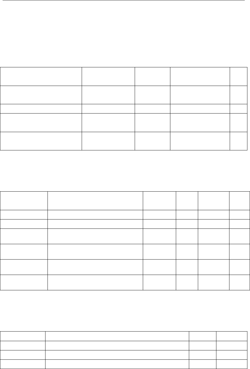
3.1 Absolute Maximum Ratings
Table 2. Absolute Maximum Ratings
PARAMETERS$DESCRIPTION$MIN$MAX$UNI
T$
Ts&Storage&
temperature&
-20&85&℃
VCC&Supply&voltage& -0.3&3.9& V&
Electrostatic&release&quantity&
(Human&body&model)&
TAMB-25℃&-& 2& KV&
Electrostatic&release&quantity&
(Machine&model)&
TAMB-25℃&-& 0.5&KV&
3.2 Electrical Conditions
Table 3. Electrical Conditions
PARAMETERS$DESCRIPTION$MIN$TYPIC
AL$
MAX$UNIT$
Ta&Temperature&for&Commercial&grade& -20& -& 85&℃
VCC&Supply&voltage&1.9&3.3&3.6& V&
VIL&IO&negative&level&input& -0.3& -& VCC*0.25& V&
VIH&IO&positive&level&input&VCC*0.75& -& VCC& V&
VOL&IO&negative&level&output& -& -& VCC*0.1& V&
VoH&IO&positive&level&output&VCC*0.8& -& VCC& V&
3.3 Transmitting Current Consumptions
Table 4. TX current consumption
PARAMETERS$MODE$TYPICAL$UNIT$
Itx&Continuously&transmitting,&7dBm&power&output& 13&mA&
Irx& Continuously&receiving&13&mA&
IDC& Normal&working&mode&80&uA&
TYLC3&DATASHEET&
4. Radio Specification
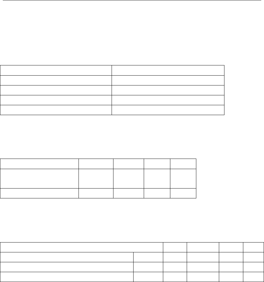
4.1 Basic Radio Frequency Characteristics
Table 5. Basic Radio frequency characteristics
PARAMETERS$DESCRIPTION$
Working&Frequency&2.4GHz&ISM&band&
Radio&standard&BLE&4.0&
Data&transmitting&rate&1Mbps
Type&of&Antenna&On-board&PCB&Antenna(default)&
4.2 Transmitting Power
Table 6. Transmitting power
PARAMETERS$MIN$TYPICAL$MAX$UNIT$
RF& Average& output& power&
consumption&
3.8& 7& -& dBm&
20dB&bandwidth& -& 1000& -& KHz&
4.3 Receiving Sensitivity
Table 7. Receiving sensitivity
PARAMETERS$MIN$TYPICAL$MAX$UNIT$
RX&sensitivity&1Mbps& -93& -92& -90&dBm&
Frequency&bias&error& -& -300& -& 300&KHz&
Co-channel&interference&Restrain& -& -& -7& -& dB&

TYLC3&DATASHEET&
5. Antenna Information
5.1 Antenna Type
Antenna can be connected using On-board PCB antenna only.
5.2 Reduce Antenna Interference
In order to have the best RF performance, it’s recommended to keep a minimum 15mm
distance between the antenna part and the other metal pieces.
TYLC3&DATASHEET&
6. Packaging Information And Production Guide
6.1 Mechanical Dimensions
Figure 3. Dimensions of the module
6.2 Production Guide
² The storage for the delivered module should meet the following condition:
1. The anti-moisture bag should be kept in the environment with temperature < 30℃ and
humidity < 85% RH.
2. The expiration date is 6 months since the dry packaging products was sealed.
² Cautions:
1. All the operators should wear electrostatic ring in the whole process of production.
2. While operating, water and dirt should not have any contact with the modules.
FCC Statement
Any Changes or modifications not expressly approved by the party responsible for
compliance could void the user’s authority to operate the equipment.
This device complies with part 15 of the FCC Rules. Operation is subject to the
following two conditions:
(1) This device may not cause harmful interference, and
(2) This device must accept any interference received, including interference that may
cause undesired operation.
FCC Radiation Exposure Statement:
This equipment complies with FCC radiation exposure limits set forth for an
uncontrolled environment .This equipment should be installed and operated with
minimum distance 20cm between the radiator& your body.
FCC Label Instructions
The outside of final products that contains this module device must display a label referring to the
enclosed module. This exterior label can use wording such as: "Contains Transmitter Module FCC
ID: 2ANDL-TYLC3 or “Contains FCC ID:2ANDL-TYLC3 , Any similar wording that expresses
the same meaning may be used.