Hangzhou Virtual And Reality Technology FOOT1 KATVR-Foot Sensor User Manual 1
Hangzhou Virtual And Reality Technology Co., LTD. KATVR-Foot Sensor Users Manual 1
Contents
- 1. Users Manual-1
- 2. Users Manual-2-1
- 3. Users Manual-2-2
- 4. Users Manual-2-3
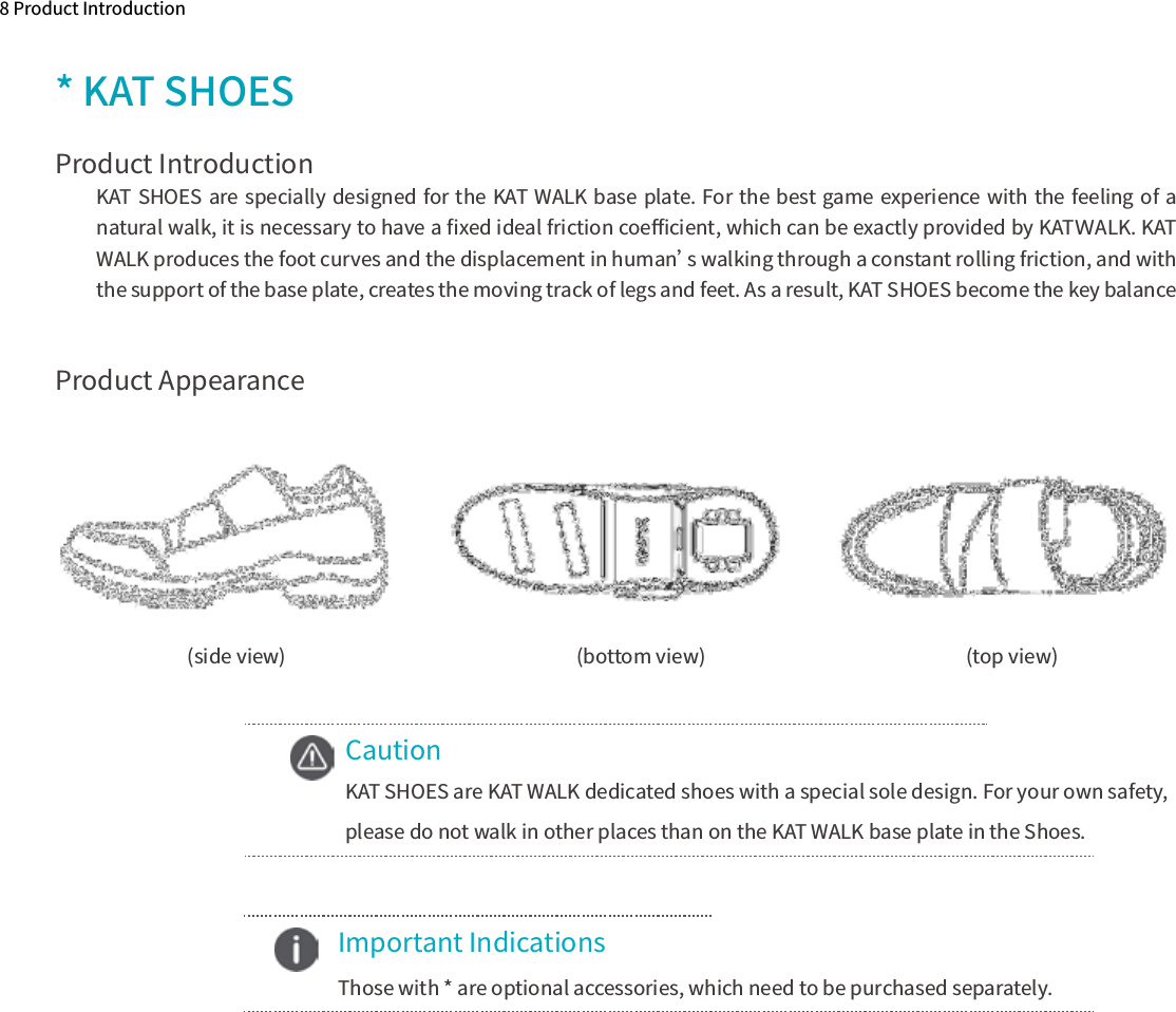
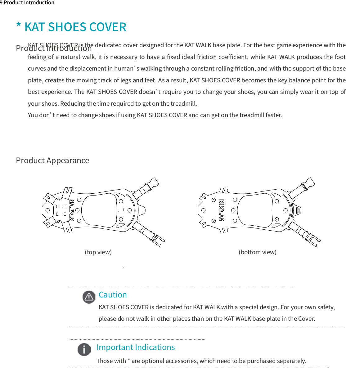
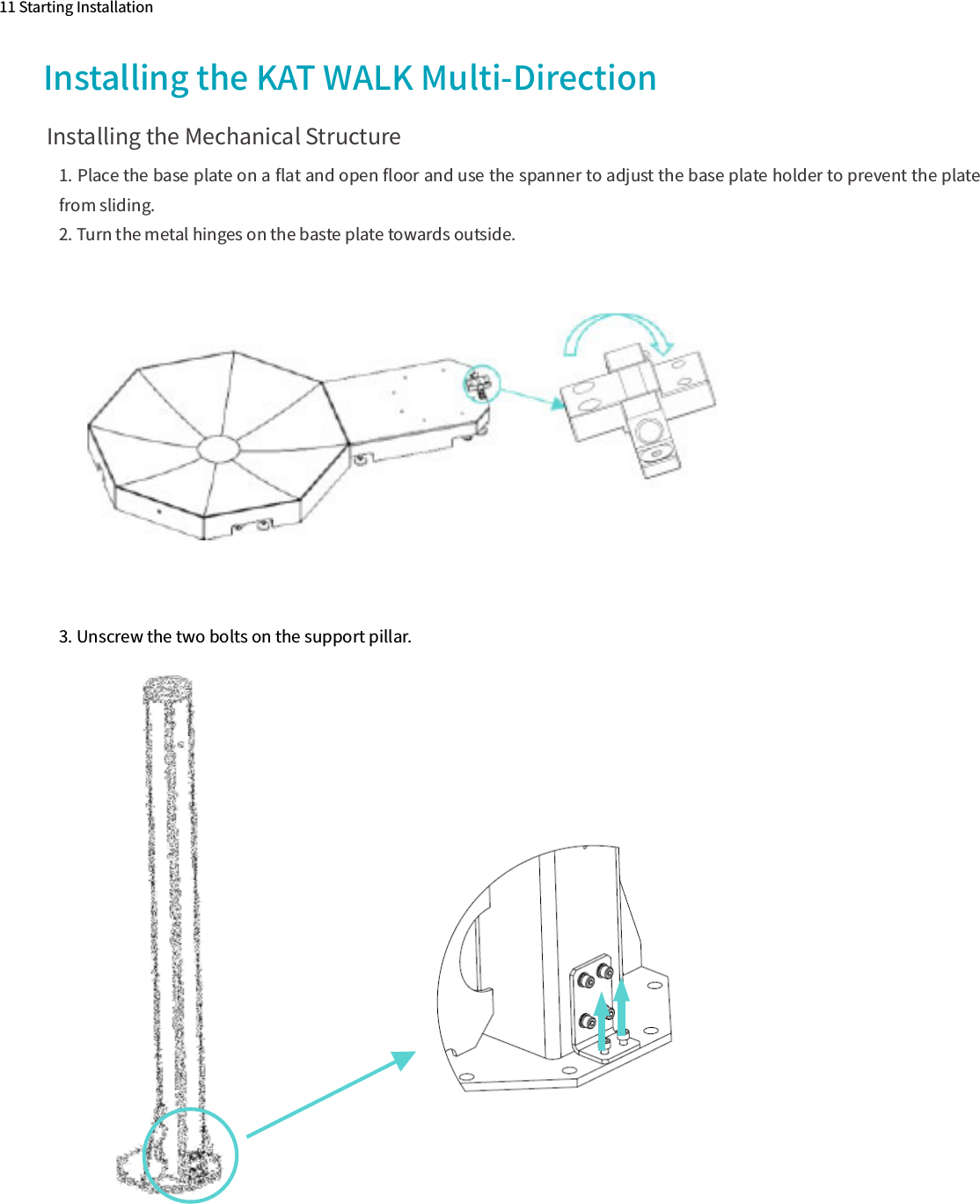
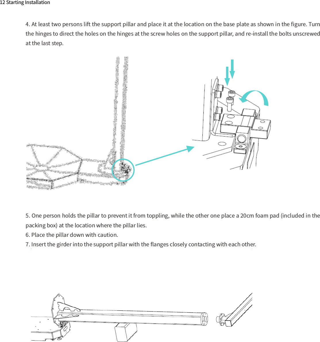
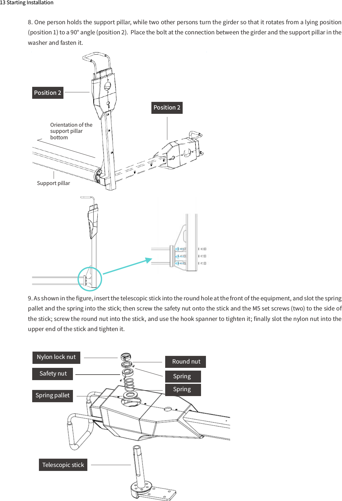
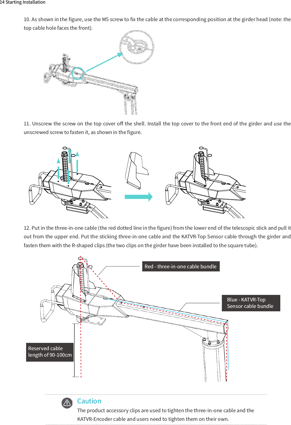
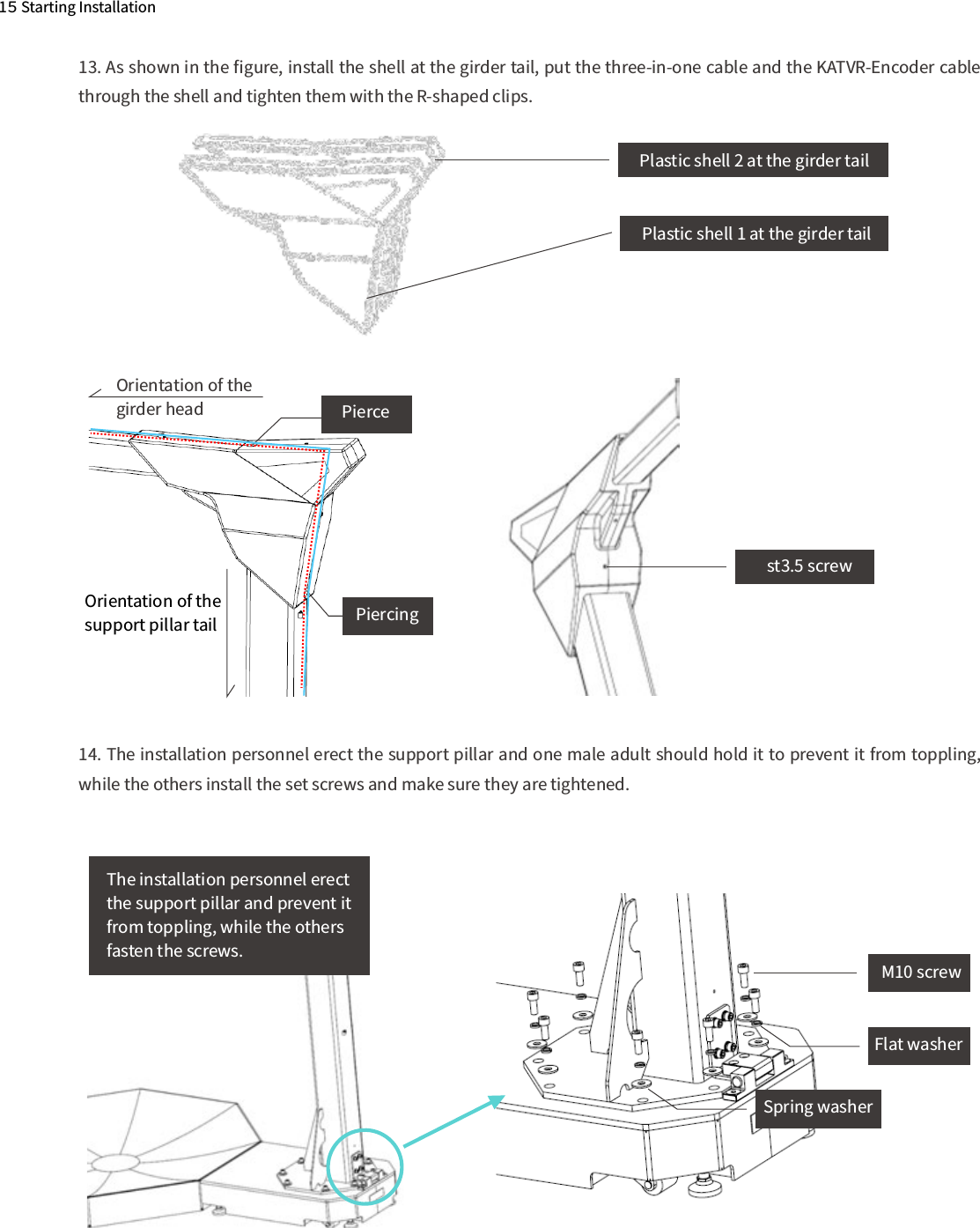
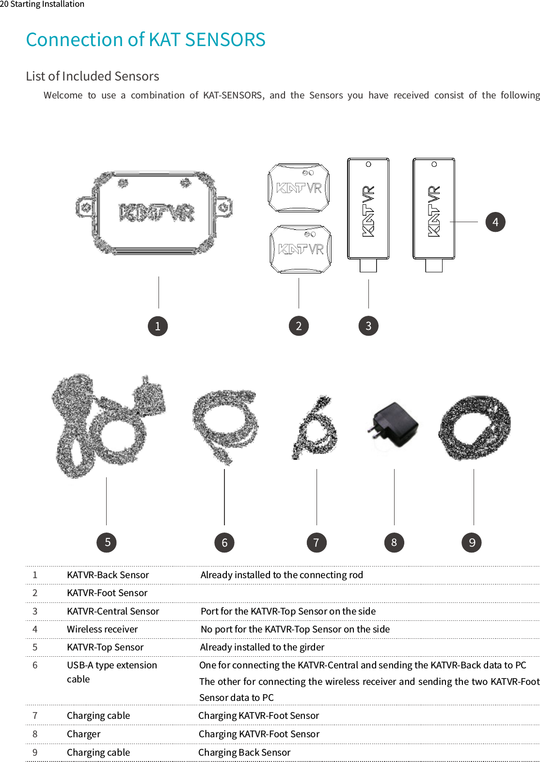
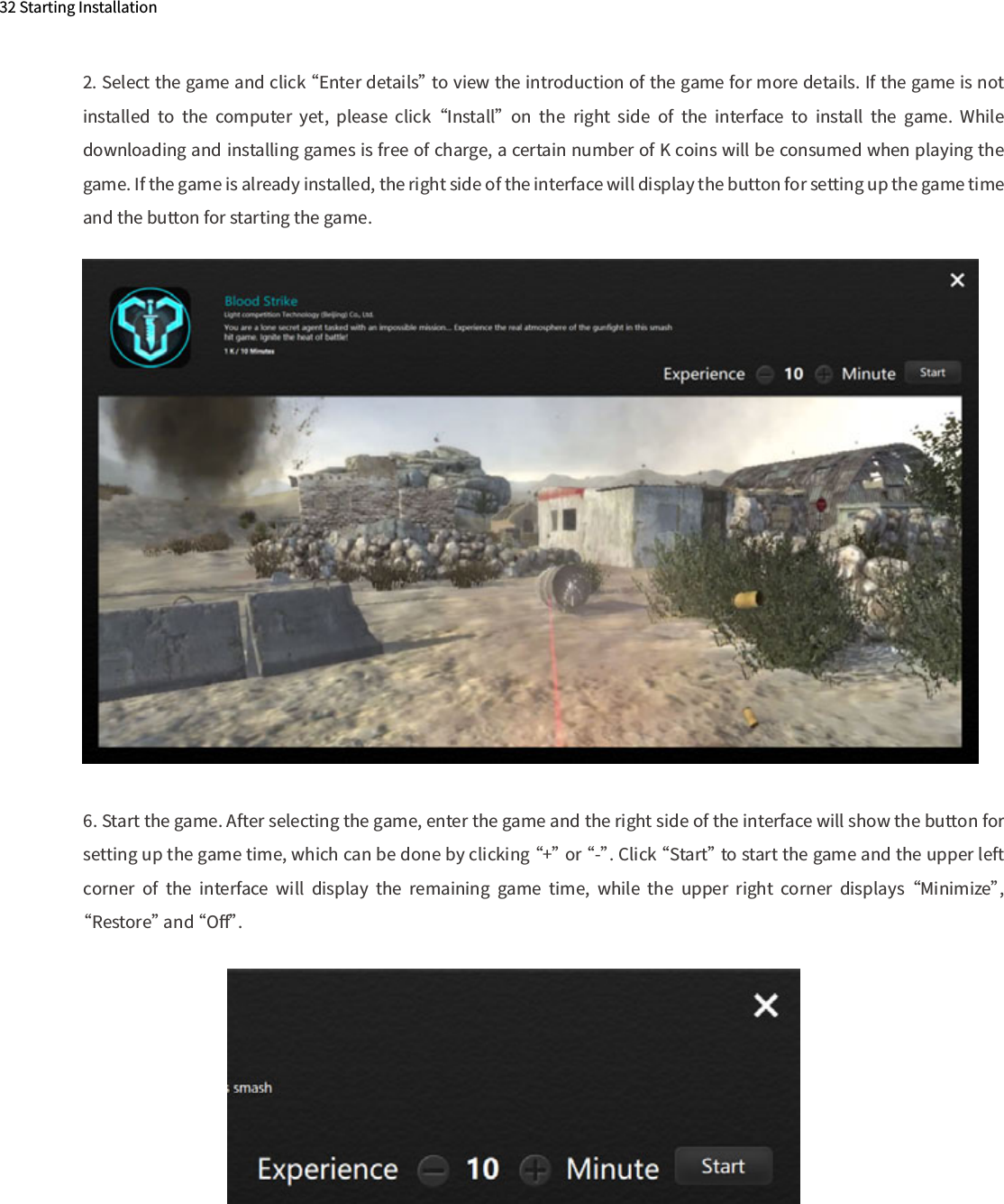
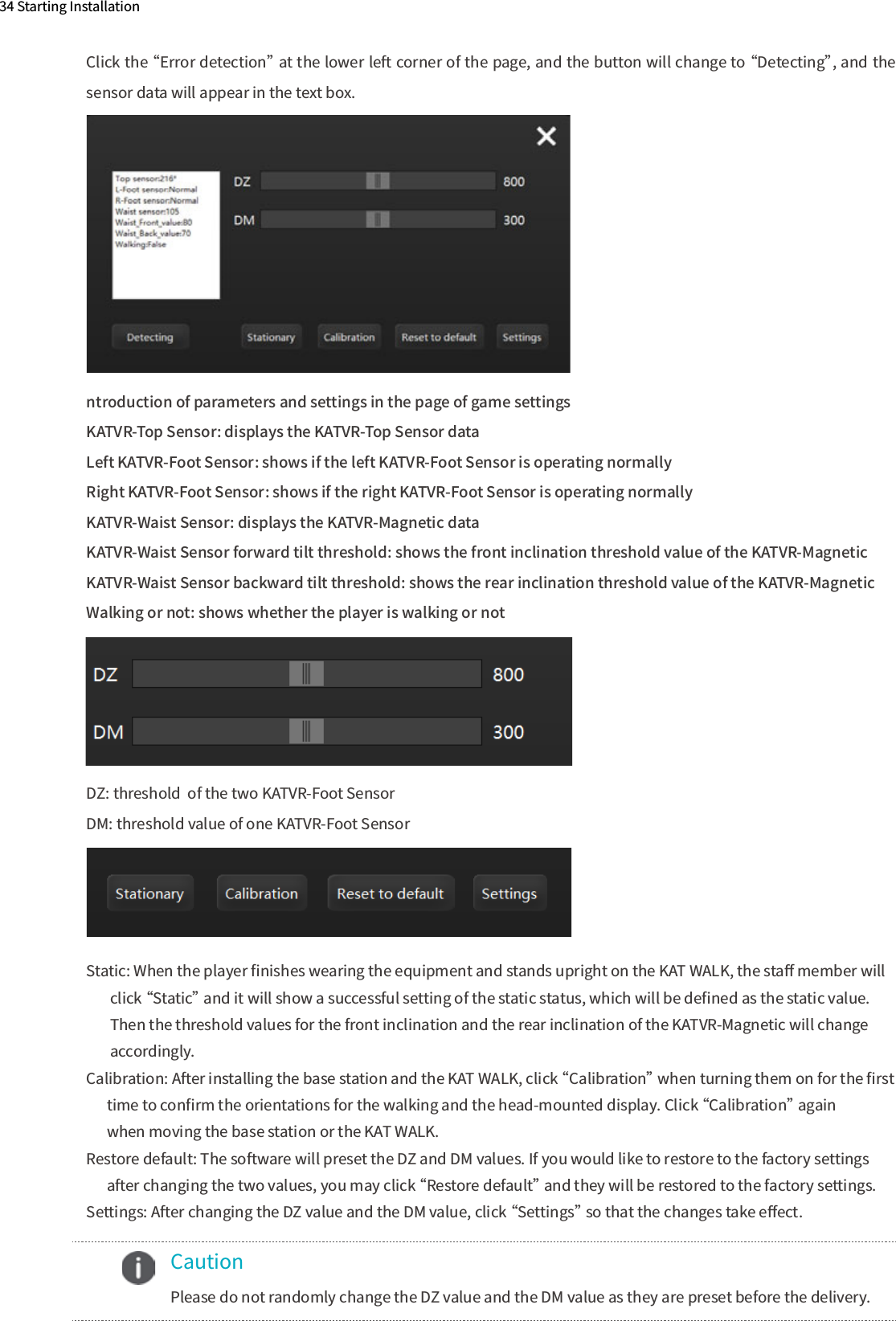
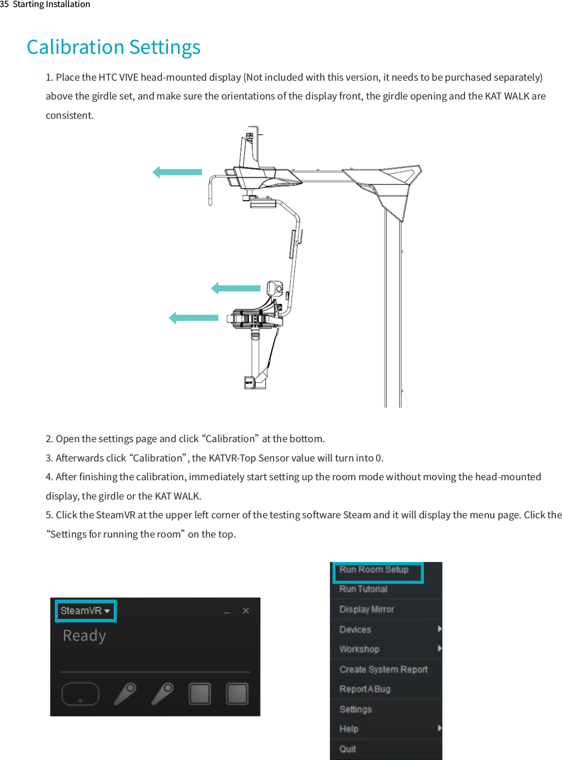
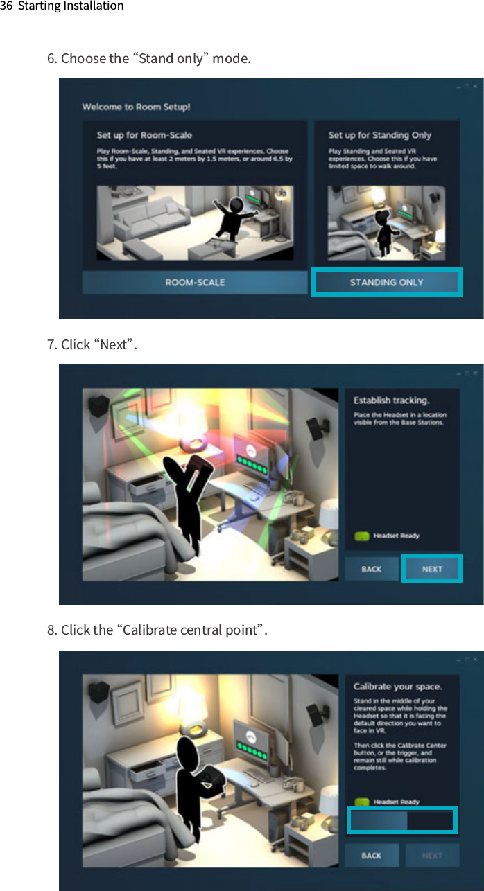
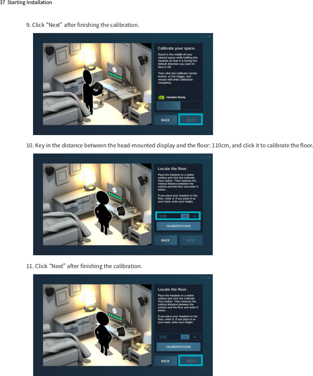
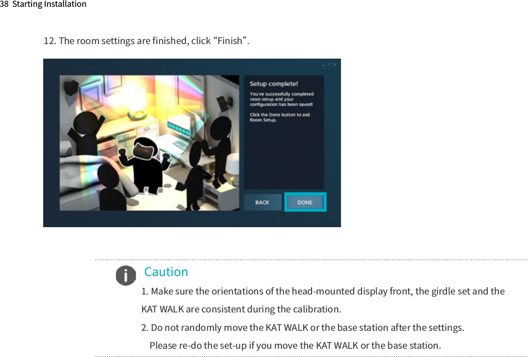
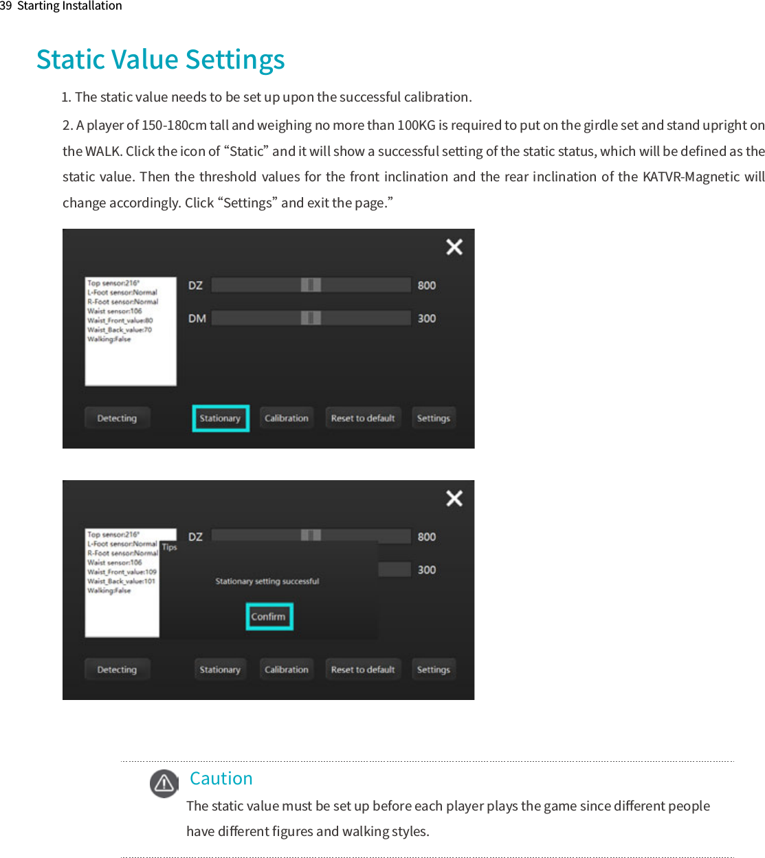
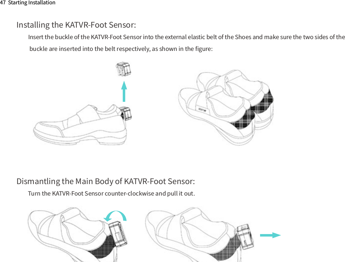
Users Manual-1