Hanna Instruments Panel Mounted Microprocessor Based Chlorine Analyzer Pca 300 Users Manual Manpca300R1
2015-02-09
: Hanna-Instruments Hanna-Instruments-Panel-Mounted-Microprocessor-Based-Chlorine-Analyzer-Pca-300-Users-Manual-563461 hanna-instruments-panel-mounted-microprocessor-based-chlorine-analyzer-pca-300-users-manual-563461 hanna-instruments pdf
Open the PDF directly: View PDF ![]() .
.
Page Count: 60

PCA 300/PCA 301
Series
Panel-mounted,
Microprocessor-based
Chlorine Analyzers
Instruction Manual

2
TABLE OF CONTENTS
PRELIMINARY EXAMINATION . . . . . . . . . . . . 4
GENERAL DESCRIPTION. . . . . . . . . . . . . . . . 5
MECHANICAL DIMENSIONS . . . . . . . . . . . . 6
FUNCTIONAL DESCRIPTION . . . . . . . . . . . . 7
LED DISPLAY, INDICATORS AND KEYBOARD . 8
SPECIFICATIONS . . . . . . . . . . . . . . . . . . . . 10
OPERATING DESCRIPTION . . . . . . . . . . . . . 12
Method of analysis . . . . . . . . . . . . . . . . 13
INITIAL PREPARATION AND INSTALLATION . 14
Installation Personnel . . . . . . . . . . . . . . 14
Location of the Instrument . . . . . . . . . . . 14
Hydraulic Connections . . . . . . . . . . . . . 14
Installing the Input Filter . . . . . . . . . . . . 16
Installing the Pump Tubes . . . . . . . . . . . 16
Electrical Connections . . . . . . . . . . . . . 18
Dear Customer,
Thank you for choosing a Hanna Product.
This instruction manual has been written for the following products:
PCA 300 Free Chlorine Analyzer with features such as alarm functions, user-se-
lectable sampling periods, LED warning indications, recorder outputs,
RS232 port and a Nema 4X, 12 and 13 enclosure.
PCA 301 Total Chlorine Analyzer with features such as alarm functions, user-
selectable sampling periods, LED warning indications, recorder outputs,
RS232 port and a Nema 4X, 12 and 13 enclosure.
PCA 300A Same as PCA 300 except for the RS232 port which is not supplied.
PCA 301A Same as PCA 301 except for the RS232 port which is not supplied.
PCA 300AC This OEM version is exactly the same as PCA 300 except for the
RS232 port and the enclosure.
PCA 301AC This OEM version is exactly the same as PCA 301 except for the
RS232 port and the enclosure.
Please read this instruction manual carefully before using the instrument. It will pro-
vide you with the necessary information for the correct use of the instrument, as well as a
more precise idea of its versatility.
These instruments are in compliance with directives. The PCA 300 and PCA 301 are
also registered by Underwriters Laboratories Inc. (UL approved).
3
START-UP . . . . . . . . . . . . . . . . . . . . . . . . . . . 22
Instrument Power On . . . . . . . . . . . . . . . . 22
Display Brightness . . . . . . . . . . . . . . . . . . 22
Minimum and Maximum Concentration . . . 23
Sampling Rate . . . . . . . . . . . . . . . . . . . . 24
Priming the Reagent System . . . . . . . . . . . 24
ANALYZER PROGRAMMING . . . . . . . . . . . . . 26
Proportional Dosing . . . . . . . . . . . . . . . . 26
Concentration Setpoint Alarm Setting . . . . . 28
Recorder Output Span Setting . . . . . . . . . . 30
Standby Mode . . . . . . . . . . . . . . . . . . . . 32
Recorder Output Calibration. . . . . . . . . . . 33
Recorder Output Limits Check . . . . . . . . . . 40
Adjusting the Light Source . . . . . . . . . . . . 42
MAINTENANCE . . . . . . . . . . . . . . . . . . . . . . 44
Calibration Requirement . . . . . . . . . . . . . . 44
Hydraulic System . . . . . . . . . . . . . . . . . . . 44
Reagents Supply . . . . . . . . . . . . . . . . . . . 44
Changing Peristaltic Pump Tubing . . . . . . . 46
Tubing Replacement . . . . . . . . . . . . . . . . 47
“Y” Strainer Cleaning . . . . . . . . . . . . . . . 47
Cleaning Measurement Cell . . . . . . . . . . . 47
Relay Test . . . . . . . . . . . . . . . . . . . . . . . . 48
Calibration Procedure . . . . . . . . . . . . . . . 48
ERROR CODES . . . . . . . . . . . . . . . . . . . . . . . 50
OPERATIONAL & DIAGNOSTIC CODES . . . . . 53
INTERFACE WITH PC. . . . . . . . . . . . . . . . . . . 55
ACCESSORIES . . . . . . . . . . . . . . . . . . . . . . . 56
WARRANTY . . . . . . . . . . . . . . . . . . . . . . . . . 57
CE DECLARATION OF CONFORMITY . . . . . . . 59
© 1997 Hanna Instruments
All rights are reserved. Reproduction in whole or in part is prohibited without the
written consent of the copyright owner, Hanna Instruments Inc., 584 Park East Drive,
Woonsocket, Rhode Island, 02895 , USA.

4
PRELIMINARY EXAMINATION
Remove the analyzer from the packing material and examine
it carefully to make sure that no damage has occurred dur-
ing shipping. If there is any noticeable damage, notify your
Dealer immediately.
Each analyzer is supplied complete with:
• 2 reagent bottles (1 indicator and 1 buffer solution)
(PCA 300 and PCA 301 only)
• 2 reagent bottle caps (PCA 300 and PCA 301 only)
• 1 DPD compound powder (PCA 300 and PCA 301
only)
• tubing
• mounting brackets
Note Save all packing materials until you are sure that the instru-
ment functions correctly. Any damaged or defective items must
be returned in their original packing materials together with
the supplied accessories.
WARNING The PCA300 and PCA 301 series of Chlorine Analyzers are
not designed for use with samples that are inflammable or
explosive in nature. If any sample solution other than water is
used with these products, test the sample/product compat-
ibility to assure user safety and proper product performance.
Safety Precautions Please take the time to read the safety precautions carefully
wherever they appear in this manual. They are provided to
prevent personal injury and damage to the instrument. This
safety information applies to the operators and service per-
sonnel and the following two captions are used:
CAUTION: identifies conditions or practices that could re-
sult in damage to the instrument or persons;
WARNING: identifies conditions or practices that could
result in personal injury or loss of life.
Note Because of the inherent dangers in handling chemical
samples, standards and reagents, HANNA Instruments
strongly recommends the users of this product review the
Material Safety Data Sheets and become familiar with safe
handling procedures and proper usage prior to handling
any chemicals.
5
GENERAL DESCRIPTION
The Hanna PCA 300 and PCA 301 series of Chlorine Ana-
lyzers are microprocessor-controlled, process analyzers which
continuously monitor a sample stream for Chlorine content.
The PCA 300 series monitor Free Chlorine and the PCA 301
series Total Chlorine in the 0 to 5 mg/L (ppm) range.
In the DPD Colorimetric method, N, N-Diethyl-p-phenylene-
diamine indicator and a buffer are mixed with the sample.
The resulting chemical reaction causes a magenta color to
form. The color intensity is proportional to the concentration
of Chlorine. The color intensity is measured photometrically
(with a light beam and a photodetector) and converted to
Chlorine concentration, in mg/L, which is displayed on the
front panel, four-digit, LED display.
Indicator and buffer reagent bottles are placed directly into
the instrument case. With a sampling period of 5 minutes,
reagents need to be replenished about once a month. The
reagent bottles are easily visible through the transparent win-
dow to allow the operator to check the reagent levels.
The cases of PCA 300 and PCA 301 meet NEMA 4X, 12
and 13 standards. Molded fiberglass polyester has outstand-
ing chemical and temperature resistance.
External mounting feet provide wall mounting capability and
a seamless gasket assures a watertight and dust-tight seal.
The electrical and hydraulic connections (except for
PCA 300AC and PCA 301AC OEM models) are made
through the side of the enclosure.
The front cover is secured with two lockable
latches.
6
Two selectable chlorine level setpoints can be set by the op-
erator: a proportional dosing setpoint and an alarm setpoint.
Both setpoints control a SPDT relay.
The proportional dosing setpoint analyzers is user-selectable
with a delta from 0.1 to 2.0 mg/L (ppm).
The alarm level can be set by the user to be an “activate-
if-lower-than” setpoint or an “activate-if-greater-than” setpoint.
A system alarm feature provides relay activation to signal
need for operator intervention.
The PCA 300 and PCA 301 analyzers can supply data to
an external computer through an RS232C output connec-
tion.
Voltage output levels of 0-10mV, 0-100mV, 0-1V or a cur-
rent output of 4-20 mA are selectable to drive an external
device such as a chart recorder or an external regulator.
Recorder span minimum and maximum values in mg/L
are programmable by the operator through the keyboard.
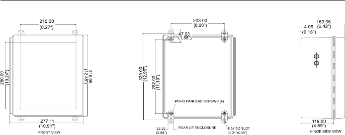
MECHANICAL DIMENSIONS *
Note The enclosure is not supplied with PCA 300AC or
PCA 301AC
* Wall Mount Dimensions in mm & inches
7
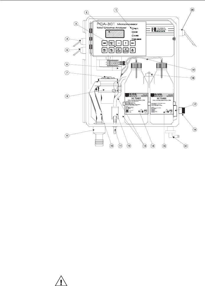
FUNCTIONAL DESCRIPTION
1. Alarms Indicators
2. LED Display
3. Keyboard
4. Alarms Output
5. Recorder Output
6. Peristaltic Pump
7. Access Point to Cell
8. Measuring Cell
9. Output Port
10. Drain Tube
11. Drain Port of Measuring Cell
12. Drain Port Valve
13. Sample Tubing
14. Buffer Bottle
15. Indicator Bottle
16. Sample Port
17. Incoming Pressure Regulator
18. Electrovalve
19. Reagent Tubing
20. Line Input
21. Pressure Regulator Output Port
Unplug the meter before any electrical connection.
8
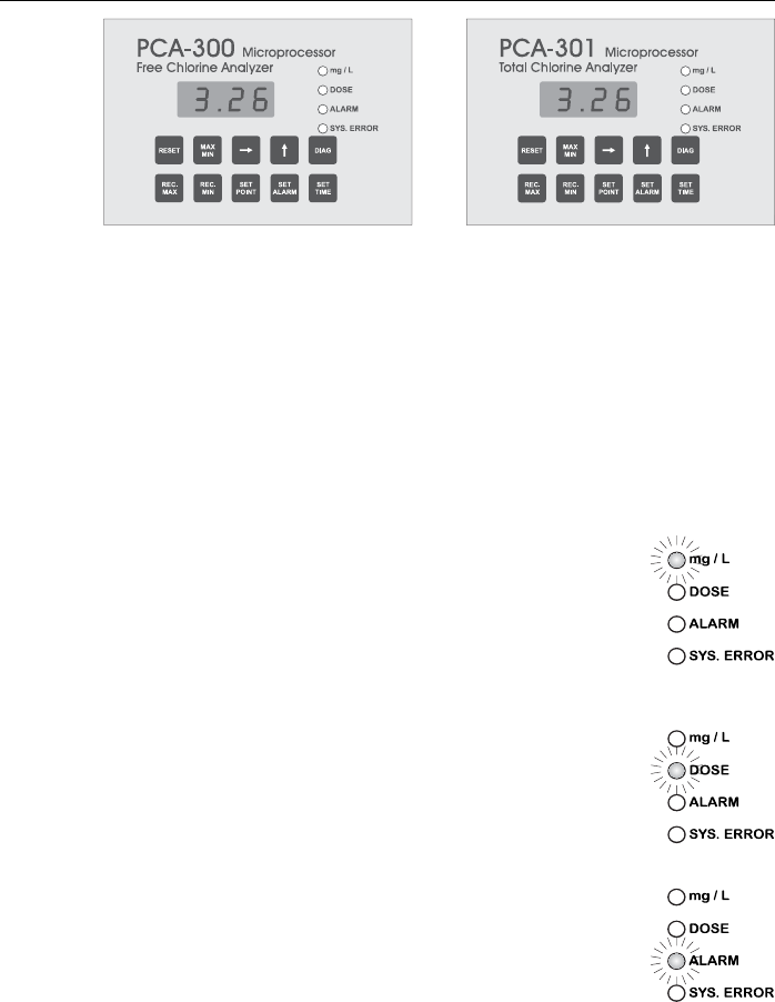
LED DISPLAY, INDICATORS AND KEYBOARD
DIGITAL DISPLAY
The digital readout will indicate the Chlorine concentration of
the last sample measured in milligrams per liter (mg/L) dur-
ing normal operation.
Only when a key is pressed to execute some other function,
will the concentration reading be interrupted. In this case, the
Chlorine mg/L indicator is turned off.
If the Chlorine concentration is above 5 mg/L, the display will
blink.
mg/L CHLORINE INDICATOR
During normal operation, this green indica-
tor will be on continuously, indicating that the
LED is displaying Chlorine concentration. Dur-
ing the diagnostic or other modes this indicator
will be off.
DOSE INDICATOR
When proportional dosing is active, the dose
LED will be on and the corresponding relay
closes. This LED turns off automatically when
the proportional dosing stops.
ALARM INDICATOR
This LED will be on when the programmed
alarm setpoints are exceeded. The alarm
LED turns off automatically when the alarm
condition disappears.
9
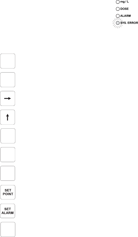
SYSTEM ERROR INDICATOR
This LED is lit when a system error has oc-
curred. If the situation persists for more than
a few samples, the operator should notify
maintenance personnel for investigation of the
problem. When the meter is in system error
mode, the user can directly access the diag-
nostic code that indicates the source of error. The analyzer
continues to perform the sampling operations during an alarm
condition.
KEYBOARD DESCRIPTION
The Reset key clears system alarm and restarts the analyzer.
The Max/Min key alternately displays maximum and mini-
mum Chlorine concentration levels since last reset.
The RIGHT arrow key is used to shift digit position within a
displayed number.
The UP arrow key is used to scroll up a displayed digit: 0, 1,
2 ..... 9, 0, 1, 2, etc.
The DIAG key is used to select programming and self-diag-
nostic modes.
The Rec.Max key is used to enter and recall maximum value
of the recorder output in mg/L.
The Rec.Min key is used to enter and recall minimum value
of recorder output in mg/L.
The Set Point key is used to enter and recall concentration
setpoint.
The Set Alarm key is used to enter and recall concentration
alarm setpoint.
The Set Time key is used to enter and recall time intervals
between two consecutive samples.
RESET
MAX
MIN
DIAG
REC.
MAX
REC.
MIN
SET
TIME

10
SPECIFICATIONS
PCA 300 PCA 301
Range 0.00 to 5.00 mg/L 0.00 to 5.00 mg/L
Free Cl2Total Residual Cl2
Resolution 0.01 mg/L
Accuracy ±8% of reading or ±0.05 mg/L
whichever is greater
Typical EMC ±0.05 mg/L
Deviation
Minimum 0.05 mg/L
detectable level
Repeatability ±0.05 mg/L
Response time Related to the sampling time selected.
Typical for a full scale step change and
5 minutes between two consecutive
samples: one sampling cycle for 90%
response and two sampling cycles for
100% response
Sampling rate Adjustable from 3 to 102 minutes
Sample inlet 0.07 bar (1psig) min., 4 bar (57.2 psig)
pressure max. An internal regulator reduces
pressure from 4 bar (57.2 psig) to
1 bar (14.3 psig)
Sample flow Flow rate of 300 mL/min is recom-
range mended. Minimum and maximum
allowed are 100 mL/min and
500 mL/min, respectively
Sample 5 to 40°C (41 to 104°F)
temperature range
Interferences Oxidizing agents such as: Iodine,
Bromine, Ozone, Chlorine Dioxide,
Permanganate, Hexavalent Chromium.
Hardness must not exceed 1000 mg/L
as CaCO3. Alkalinity must not exceed

11
400mg/L for Free Chlorine analysis (PCA
300) or 700mg/L for Total Chlorine
analysis (PCA 301)
Operating 5 to 40°C (41 to 104°F)
temperature range
Recorder output Selectable 0-10mV, 0-100mV, 0-1V or
4-20 mA. Output span is settable
anywhere in the 0-5 mg/L range
Dosage Proportional on one point with a delta
adjustable at 0.1, 0.2, 0.3, 0.4, 0.5,
0.6, 0.7, 0.8, 0.9, 1.0, 1.5, 2.0 mg/L,
equipped with a SPDT relay with
contacts rated for resistive load: 5 A at
250VAC or 5 A at 30VDC; inductive
load: 2 A at 250VAC or 3 A at 30VDC.
Alarms One sample concentration alarm
adjustable as minimum or maximum
acceptable value, equipped with a
SPDT relay with contacts rated for
resistive load: 5 A at 250VAC or 5 A at
30VDC; inductive load: 2 A at 250VAC
or 3 A at 30VDC.
One system error alarm
Power 20VA at 115VAC/230VAC;
requirements 50/60 Hz
Sample inlet 12 mm (1/2”) male NPT fitting
connection
Drain connection 10 mm (3/8”) barb fitting
Case NEMA-4X molded fiberglass polyester
instrument enclosure with transparent
GE Lexan window (not PCA 300AC and
PCA 301AC)
Dimensions 318 x 267 x 159 mm
(12.5 x 10.5 x 6.25")
Weight 5 Kg (11 lb.)

12
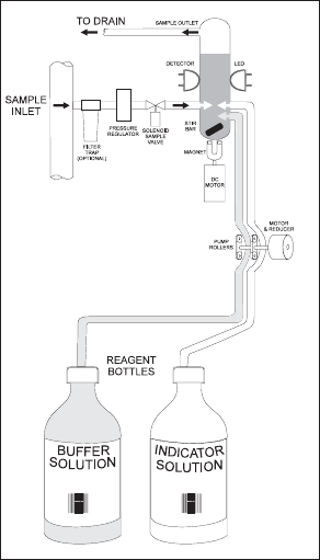
OPERATING DESCRIPTION
Referring to the drawing on page 7 and the Fluidic Dia-
gram on page 13, the Sample Line is connected to the
instrument at the Sample Port (#16); an internal Regulator
(#17) reduces the inlet pressure from a maximum of 4 bar
(57.2 psig) down to 1 bar (14.3 psig); from the Regulator
a nylon tube is connected to the input of the Electrovalve
(#18). The output of the valve goes to the Drain Port (#11
in PCA 300 and PCA 301 only) and then to the Measur-
ing Cell (#8). An optional Filter can be installed to the sample
port if the stream is excessively turbid.
The sample coming from the line normally flows through the
Measuring Cell. It goes out from the Measuring Cell through
the Drain Tube (#10) and the Output Port (#9).
The Measuring Cell is accessible from the port placed on the
top (#7) for speedy cleaning and maintenance.
During the time between two successive sampling, the ana-
lyzer solenoid input valve is open to allow sample flow to
flush the colorimeter cell. Every 3 to 102 minutes (user se-
lectable), the valve closes stopping the sample flow and
leaving the sample cell full of fresh sample. Cell volume is
controlled by an overflow gateway.
As the sample inlet valve closes, a series of measurements
(with LED on and off) of the unreacted sample is taken to
determine an average Blank level prior to reagent addi-
tion. The measurement of sample blank signal permits
compensation for any turbidity or natural color, and pro-
vides the zero reference point for the measurement.
The two channel Peristaltic Pump (#6) starts rotating caus-
ing a precise quantity of buffer and indicator (#14 and
#15) to enter the colorimeter sample cell where a mag-
netically coupled stirrer mixes the reagents with the sample.
After a delay for the development of color, a series of mea-
surements (with LED on and off) are taken (Sample level)
to determine an average Chlorine concentration measure-
ment. The reacted sample signal is then measured and
displayed.
This sequence is repeated every 3 to 102 minutes (user-se-
lectable).
13
METHOD OF ANALYSIS
Free available Chlorine (monitored by the PCA300 series)
oxidizes the DPD indicator reagent at a pH between 5.5 and
6.0 to form a magenta-colored compound. The intensity of
the resulting color is proportional to the concentration of Chlo-
rine in the sample. The purpose of the buffer solution is to
maintain the proper pH.
To measure Total Residual Chlorine (Free available Chlorine
plus combined Chloramines) the PCA301 series adds Po-
tassium Iodide. The Chloramines in the sample cause
iodide ions to become iodine which then act with free Chlo-
rine to oxidize the DPD indicator. After the chemical reaction
is complete, the optical signal at 555 nm is compared to
the signal measured through the sample (before the re-
agents were added). From these measurements Chlorine
concentration is calculated.
Fluid Diagram of the Analyzers

14
INITIAL PREPARATION AND INSTALLATION
INSTALLATION PERSONNEL
Installation of the PCA 300 and PCA 301 family of Chlo-
rine Analyzers should be undertaken by persons with technical
knowledge of the dangers associated with chemical exposure
and electrical shock.
Hanna Instruments assumes persons performing the instal-
lation tasks are aware of the appropriate safety procedures.
Review the Material Safety Data Sheets (MSDS) before han-
dling the supplied chemical reagents.
LOCATION OF THE INSTRUMENT
Analyzer Location
Locate the analyzer as close as is reasonably possible to
the point where the sample is withdrawn from the product
stream (referred to as the “sampling point”). This practice
will minimize the amount of time it takes for the sample to
flow to the analyzer from the sampling point. The result is
improved response time of the analyzer to changes in Chlo-
rine contents.
The instrument should be mounted indoors, out of direct
sunlight. Instrument operating temperature is 5 to 40°C
(41 to 104°F).
Sampling Point Location
Locate the sampling point to obtain a truly representative
sample from the product stream. For example, be sure the
sampling point is well downstream from a Chlorine feed.
This assures that adequate mixing and reaction of the
Chlorine before a sample is extracted.
HYDRAULIC CONNECTIONS
Note Hydraulic connections should be installed only by qualified
personnel to assure conformity to applicable plumbing codes.
Sample Line Installation
Sample lines of 3 mm (1/8") ID tubing are recommended to
keep the sample volume in the tubing to a minimum. This
reduces lag time for the sample flow from the sampling point
to the instrument. In any case note that sample should reach
the measuring cell in less then 100 seconds.
15
Direct routing of sample lines is also recommended.
If the large process pipes are horizontal, taps should be in-
serted vertically in the middle of the pipe to avoid pulling
sediment from the bottom or air bubbles from the top of
the pipe into the sample line.
A 1/2” BSP sample input fitting allows direct connection to
the optional input filter.
Sample line pressure should be between 0.07 and 4 bar (1
and 57.2 psig) with an ideal pressure of 0.7 bar (10 psig).
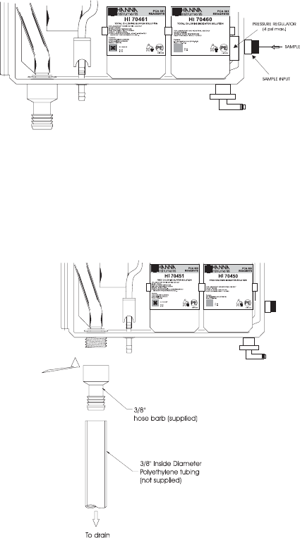
Drain Line Installation
The drain hose fitting is a 20 mm (3/4”) hose barb on the
bottom of the instrument enclosure. An air gap between the
end of the drain hose and the drain is recommended to prevent
any back flow into the instrument in the event of drain block-
age.
16
Return Line Installation
The return hose fitting is a 12 mm (1/2”) hose barb on the
bottom of the regulator output port and should always be
connected even when pressure is below 1 bar.
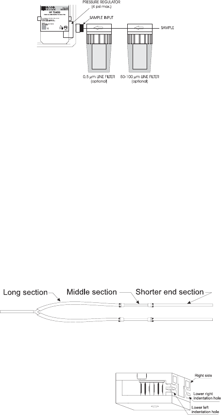
INSTALLING THE INPUT FILTER
In order to ensure maximum accuracy of measurements, it is
recommended to have always clear sample, with suspended
particles smaller than 0.5 µm. This can be achieved by in-
stalling two filters before the sample input.
The type of filters depends on the quality of the water: the first
filter should have 50-100 µm pore size, whereas in any case
the second filter, the one closer to the analyzer, has to be
0.5 µm.
For correct installing procedure and maintenance, see the
instructions of filters.
INSTALLING THE PUMP TUBES
Locate the analyzer reagent tubes in the accessory kit. Each
tube is composed of three sections. The sections are joined
together by plastic connectors with plastic collars at the ends
of the center section.
Locate the peristaltic pump.
Feed one tube from the shorter end section behind the pump
rollers from the right side of the pump. Seat the plastic collar
at the right end of the center sec-
tion of tubing into the lower right
indentation hole of the pump face.
17
Grasp the other plastic collar and pull, stretching the center
section, and place the grommet in the lower left indentation
hole.
Repeat this process with the second pump tube, placing it in
the upper indentation holes.
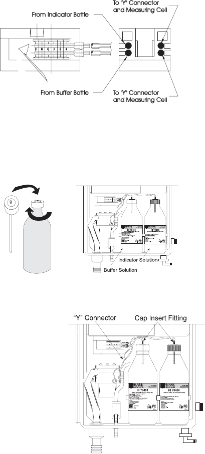
Separate reagent caps are provided in the accessory kit. Put
the supplied caps onto each reagent bottle prior to installing
them. Place the indicator bottle (HI 70450 for PCA 300
and HI 70460 for PCA 301) on the right and the buffer
bottle (HI 70451 for PCA 300 and HI 70461 for PCA
301) on the left.
Note Add the content of 5 HI 70452 sachets, DPD Compound,
to the Indicator Solution prior to installing it.
Connect the longer tube
ends on the left side of
the pump to the reagent
bottle cap insert fitting.
Connect the short ends
on the right side of the
pump to the measuring
cell reagent input port
through the "Y" connec-
tor.
18
ELECTRICAL CONNECTIONS
A power cable (3 mt.) is provided with your analyzer. How-
ever, if access to the terminal block is required, see below.
Warning Electrical connections should be installed only by qualified
personnel to assure conformity to applicable electrical codes.
Unplug the meter before any electrical connection.
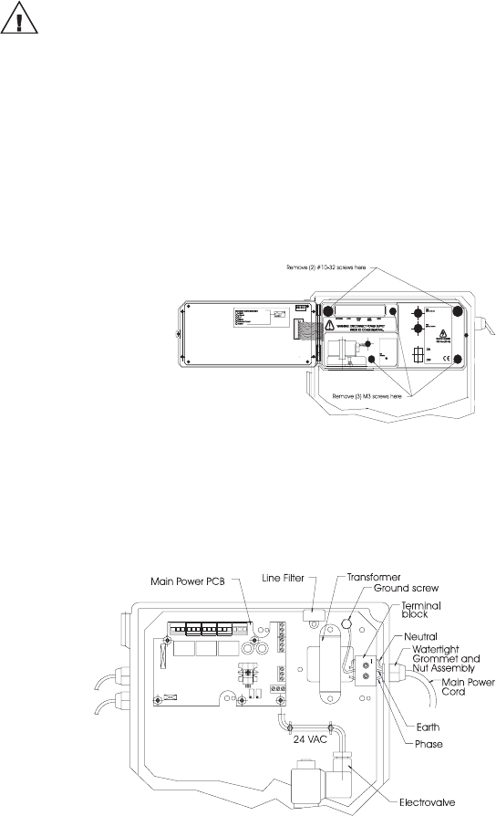
Power
Power connections are made at a terminal block located in
the center of the electrical compartment to the right of the
fuses.
Hard wiring with 13 mm (½") conduit is recommended and
usually required by most municipal electrical codes.
Warning Before connecting the instrument to the line:
1) Check the sticker near the fuses for proper voltage.
2) Be sure the power cord is not connected to the line.
3) Open front panel.
4) Remove the cover screws (Allen head).
5) Do not remove peristaltic pump or motor.
6) Unplug all alarms and recorder jacks.
Feed the power cord through the watertight grommet and
tighten the grommet nut. See the picture below for proper
wire connections.
19
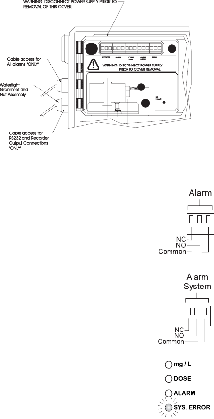
Recorder Output and Relay Access
Hard wiring for alarms and relays can be accomplished
through four watertight connectors on the left of the enclo-
sure, by passing wires through the rubber grommet and
tightening the nut as described earlier.
Refer to the drawing on the right for proper wire connections.
Alarm System
A system alarm feature provides relay acti-
vation to signal need for operator
intervention through an external device, such
as a buzzer, a light or any other electrical
equipment.
Refer to the drawing on the right for proper
wire connections.
The SYS.ERROR LED goes on when a sys-
tem error has occurred. If the situation persists
for more than a few samples, the operator
should notify maintenance personnel for in-
vestigation of the problem. When the meter
is in system error mode, the user can di-
rectly access the diagnostic code that
indicates the source of error (see Error Codes
section at page 49). The analyzer continues
to perform the sampling operations during
an alarm condition.
20
Recorder Output
Recorder output connections are made as indicated on the
picture aside. The control panel must be opened.
A wiring access hole is located on the left side of the instru-
ment case. Use two wire shielded cable with the shield
connected at the analyzer end only. This wire access hole
should be used only for recorder or serial I/O cables (low
voltage).
The recommended recorder hookup uses a
shielded, twisted-pair cable. The shield
should be connected to Earth terminal at
the instrument end and left open at the re-
corder end. Refer to the drawing here for
proper wire connections.
To operate with this hookup, the following conditions are re-
quired at the recorder end:
• The input to the recorder must be isolated from the chassis
ground (earth) of the recorder;
• If the recorder has more than one input, they must be dif-
ferential inputs.
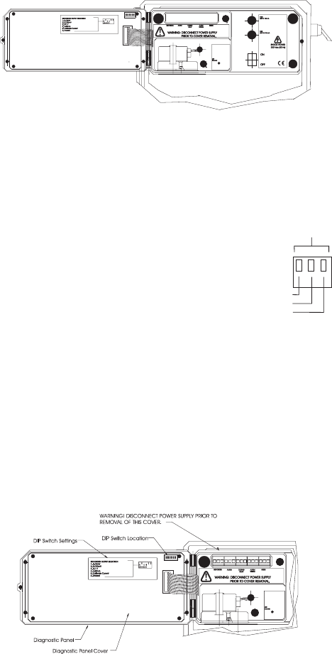
A choice of outputs, 0-10mV, 0-100mV, 0-1V or 4-20 mA
may be made by selecting the appropriate DIP switch con-
figuration. The DIP switch is located in the upper right corner
of the main board on the back of the control panel.
Earth
Ground
Out
Recorder
Output
21
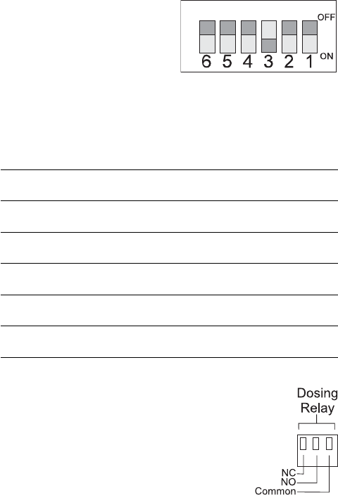
Set the individual micro-switch
for the desired output in the ON
position (e.g. 0-1V).
See table below.
Switch Function
6 Not used
5 Calibrate Current
4 4 - 20 mA
30 -1 V
2 0 -100 mV
1 0 -10 mV
Dosing Pump
Proportional dosing can be performed
connecting an external pump to the
DOSING RELAY block terminal.
For the correct connection, see the drawing
aside.
22
START-UP
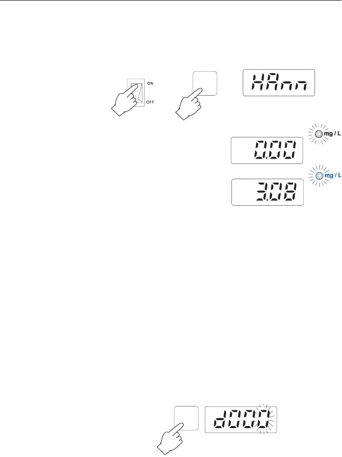
INSTRUMENT POWER ON
When the POWER switch is turned on or RESET is pressed,
the moving words “Hanna PCA300” will appear. This dis-
play will continue for 20 seconds.
Then the concentration is set to
0.00 mg/L.
An indication appropriate to
the key pressed or, after 5
minutes, the first mg/L read-
ing will appear on the display.
Note The SYS.ERROR LED and relay will not activate before the
first reading.
Be sure the sample stream is open and flowing through the
system. Wait long enough for the tubing and colorimeter to
be flushed and filled completely and for the reading on the
digital display to become stable.
If no priming action is taken, one or two hours may be re-
quired to initialize the instrument. Faster stabilization can be
obtained by priming the reagent pump and tubing using the
provided operational code.
DISPLAY BRIGHTNESS
The display brightness is set at the highest level. The analyzer
offers the option to change it at two lower levels.
• Press DIAG. The display will show the last diagnostic mode
and the right-most numerical digit will blink.
Note If the analyzer has been reset or turned on, “d000” will ap-
pear when pressing DIAG.
RESET
DIAG
23
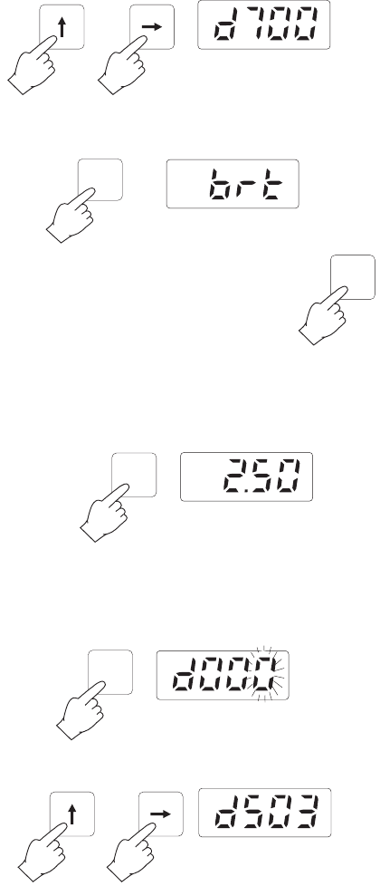
• Enter code 700 using the and keys.
• Press DIAG and “brt” will be displayed. Then the bright-
ness of the display will begin to change through the three
levels.
• Press DIAG at one of the 3 brightness level
and the analyzer will store that brightness
level. If DIAG is not pressed, the brightness
will remain at the present level.
MINIMUM AND MAXIMUM CONCENTRATION
In any moment it is possible to recall the current minimum
and maximum chlorine values taken since the last reset.
Simply press MAX/MIN and the display will show alternately
the two levels.
After a few seconds the display will revert to the last reading.
To clear the current minimum and maximum concentrations,
press DIAG. The display will show the last diagnostic mode
and the right-most numerical digit will blink.
Enter Priming code 503 using the and keys.
DIAG
DIAG
MAX
MIN
DIAG
24
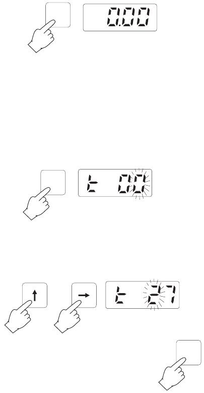
Press DIAG. “0.00” will appear on the display and the two
levels will be set to the current value.
SAMPLING RATE
The sampling rate is user-selectable from a minimum of a
measurement every 5 minutes to a maximum of one every 90
minutes.
It is possible to recall and change the interval between two
different measurements at any given moment.
Simply press SET TIME.
Select the desired interval between 5 and 90 using the and
keys. The unit will not allow the user to enter a value less
than 5 or greater than 90.
Press SET TIME twice to store the new sampling
interval setting and revert normal operational
mode.
SET
TIME
DIAG
SET
TIME
25
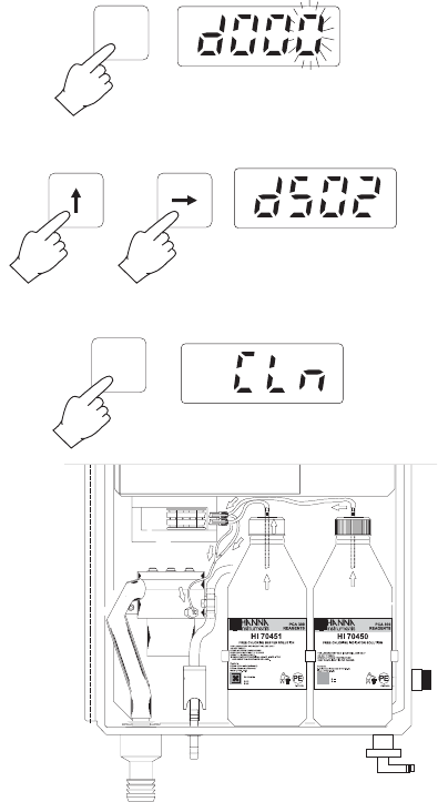
PRIMING THE REAGENT SYSTEM
A special diagnostic function included in the software pro-
vides a convenient way to prime the peristaltic pump and
reagent tubing during initial start-up. This decreases the time
needed for instrument stabilization to about three minutes or
until DIAG is pressed again.
1. Press DIAG. The display will show the last diagnostic mode
and the right-most numerical digit will blink.
2. Enter priming code 502 using the and keys.
3. Press DIAG to execute priming sequence. The display will
show “CLn”.
4. Repeat the procedure if necessary, until the reagents lines
are completely primed from the bottles to the colorimetric
sample cell.
DIAG
DIAG
26
ANALYZER PROGRAMMING
When power is first applied to the analyzer, programmable
parameters of the analyzer are set to default values estab-
lished at the factory. These values or any new values entered
by the operator are stored in nonvolatile EEPROM which
will retain the programmed values in the event of power
failure. All programmable parameters are viewed or ad-
justed via dedicated push buttons.
To check the setting of any programmable parameters, sim-
ply press the dedicated key and the setting will be shown
on the display.
To change the setting, enter the
new setting into the display using
the and keys and then quickly
press the dedicated key twice .
The display will show the entries for approximately 2 sec-
onds after the last key stroke and after altering programmable
parameters. The display will
then revert automatically to a
Chlorine concentration display.
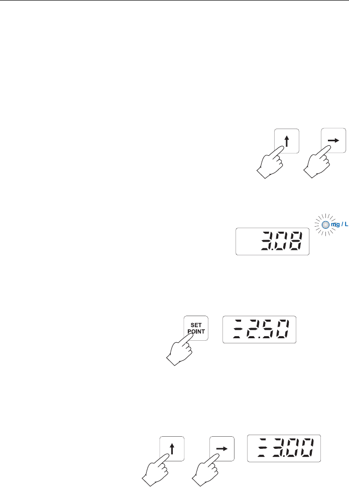
PROPORTIONAL DOSING
Proportional dosing establishes and maintains a controlled
and consistent concentration level.
• Press SETPOINT. The display will show the current dosing
setpoint.
Note If the analyzer has been turned on for the first time, “2.50”
will appear as default setpoint.
• Enter the desired setpoint value, e.g. 3.00, using the
and keys.
27
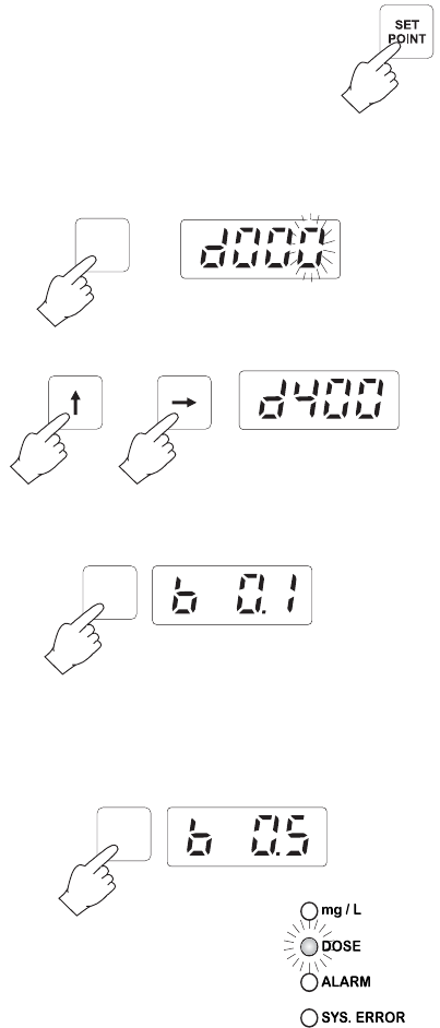
• Press SETPOINT twice to store the new set-
point.
• To set the range within which the proportional dosing occurs
(delta), press DIAG. The display will show the last diag-
nostic mode and the right-most numerical digit will blink.
• Enter code 400 using the and keys.
• Press DIAG and the possible settings, 0.1, 0.2, 0.3, 0.4,
0.5, 0.6, 0.7, 0.8, 0.9, 1.0, 1.5, 2.0, will scroll.
Note If the analyzer has been reset or turned on, “0.1” is the de-
fault delta.
• Store the desired delta, e.g. 0.5, pressing DIAG when the
desired value appears.
• When dosing is active, the DOSE
LED turns on and the corresponding
relays closes.
Note If the measured concentration is lower than the delta, the
dosing will be continuous until the next measurement is taken.
DIAG
DIAG
DIAG
28
Example With the previously given values, sample rate 5 minutes and
measured value 2.8 mg/L, the proportional dosing will be
active for the initial 2 minutes and will stop for the remaining
3 minutes. In fact:
0.5 mg/L : 5 min = 0.2 mg/L (3-2.8) : X
then X = 2 minutes.
CONCENTRATION SETPOINT ALARM SETTING
PCA 300 and PCA 301 are equipped with a fully program-
mable concentration alarm that will activate an indication
when the chlorine concentration limit is exceeded. The alarm
can be set to actuate at any point from 0.00 to 5.00 mg/L.
• To set the concentration level alarm setpoint, press
SET ALARM and the display will show the previously pro-
grammed setpoint.
Note If the analyzer has been turned on for the first time, “0.00”
will appear as default setpoint.
• Using the and keys set the new the mg/L Chlorine
value as desired alarm level (e.g. 2.50 mg/L).
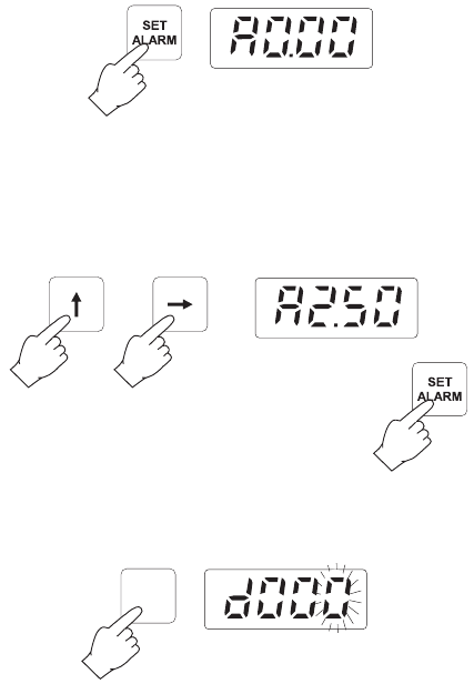
• Press SET ALARM twice to set the alarm level.
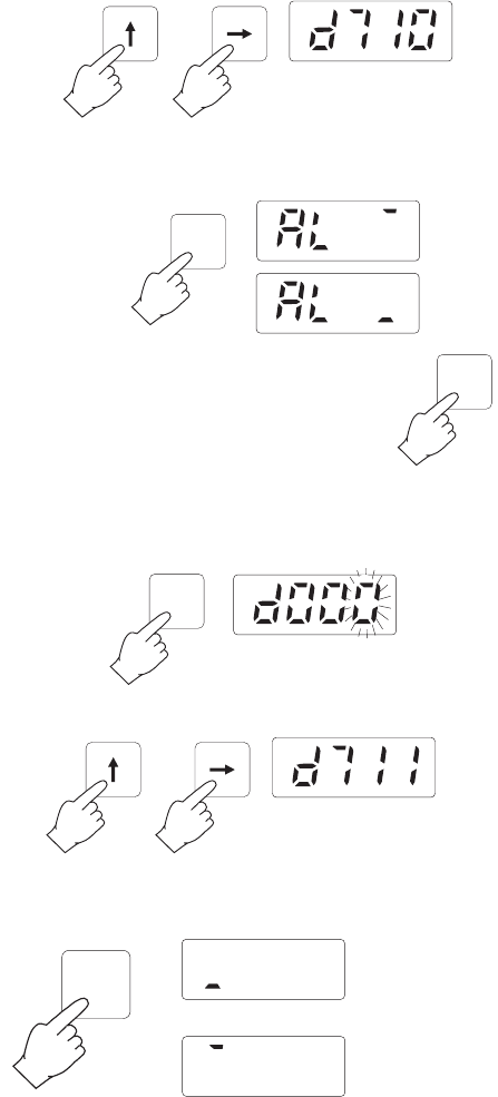
• To set the stored value as a minimum or
maximum level, press DIAG. The display will show the last
diagnostic mode and the right-most numerical digit will
blink.
DIAG
29
• Enter code 710 using the and keys.
• Press DIAG and the display will scroll through “AL —”,
maximum desired level, and “AL —”, minimum desired level.
• Press DIAG when the needed condition
appears.
• To see the current alarm logic (high or low alarm), press
DIAG. The display will show the last diagnostic mode and
the right-most numerical digit will blink.
• Enter code 711 using the and keys.
• Press DIAG and the display will show if the current alarm is
set as minimum (LOW) or maximum (HIGH) desired level.
LOW
HIGH
DIAG
DIAG
DIAG
DIAG
30
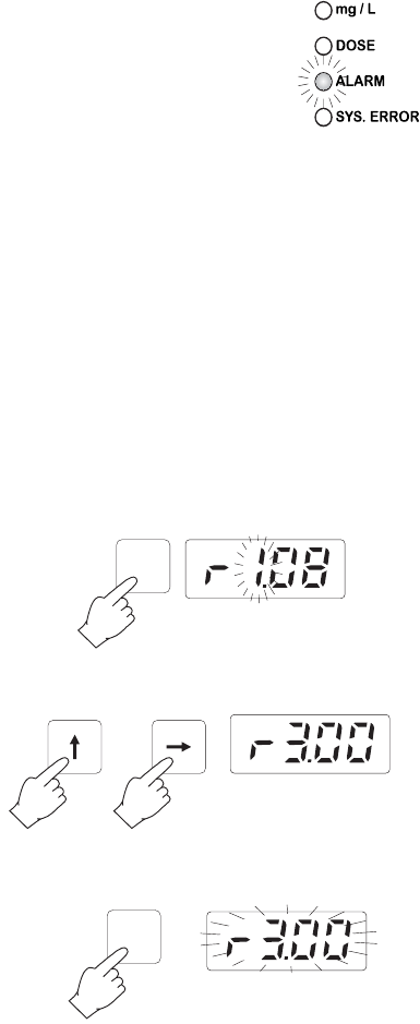
• When an alarm condition is met, the
ALARM LED turns on and the corre-
sponding relays closes.
RECORDER OUTPUT SPAN SETTING
The selected recorder output voltage range or the 4-20 mA
current output may be associated with any Chlorine concen-
tration in the 0 to 5 mg/L range.
For example, if the 0.0 to 1.0 V recorder output has been
selected, the operator can select 0.0 V to correspond to a
concentration of 3.0 mg/L (Recorder Minimum setting) and
1.0 V to correspond to a concentration of 4.5 mg/L (Re-
corder Maximum setting). The full scale span of the recorder
would then be 1.5 mg/L, yielding a magnified view of the 3.0
to 4.5 mg/L concentration range on the recorder.
To set the lower limit of the recorder output
• Press REC.MIN. Display will show the previously set mini-
mum recorder level (e.g. 1.08 mg/L). The most signifi-
cant digit will be blinking.
• Using the and keys set the new minimum recorder
level (e.g. 3.00 mg/L).
• Press REC.MIN a second time. The display will blink the
new setpoint for the low end of the recorder output.
REC.
MIN
REC.
MIN
31
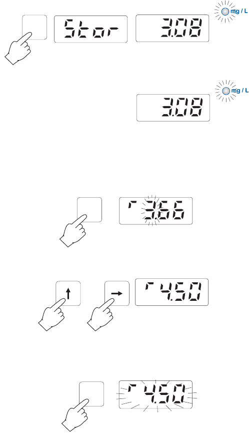
• If you want to store the new setpoint promptly press REC.MIN
again. Display will show “Stor” for a short time indicating
that the new setpoint is stored and will return to the Chlo-
rine concentration display.
• If you do not want to change
the setpoint, do not press
REC.MIN a second time. The
display will return to the Chlo-
rine concentration display and
the setpoint will not be changed.
To set the higher limit of the recorder output
• Press REC.MAX. The display will show the previously set
maximum recorder level (e.g. 3.66 mg/L). The most sig-
nificant digit will be blinking.
• Using the and keys set the new maximum recorder
level (e.g. 4.50 mg/L).
• Press REC.MAX a second time. The display will blink the
new setpoint for the high end of the recorder output.
REC.
MAX
REC.
MAX
REC.
MIN
32
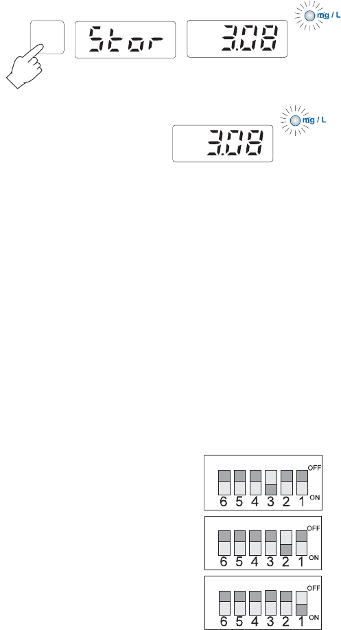
• If you want to store the new setpoint, promptly press
REC.MAX again. Display will show “Stor” for a short time
indicating that new setpoint is stored and will return to the
Chlorine concentration display.
• If you do not want to change
the setpoint, do not press
REC.MAX a second time.
The display will return to the
Chlorine concentration dis-
play and the setpoint will not
be changed.
RECORDER OUTPUT CALIBRATION
The PCA 300 and PCA 301 series of Analyzers are capable
of self-calibrating the voltage or current limits to ensure a 0-
1V output is truly 0-1V or 4-20 mA output is exactly 4-20
mA. This programmed capability eliminates the need for a
voltmeter or milliammeter for output calibration. Calibrating
the recorder output involves a two part procedure. First, a
coarse adjustment to set the voltage (follow step 1 below) or
current limit (follow step 2 below) is completed. Secondly a
fine tuning (step 3 below).
Step 1
If a voltage output has been selected as:
1 V (load > 50 kΩ)
100 mV (load > 5 kΩ)
10 mV (load > 500 Ω)
REC.
MAX
33
voltage limits can be calibrated automatically as follows:
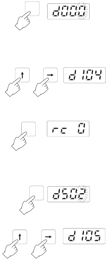
1.A To automatically calibrate "ZERO" scale
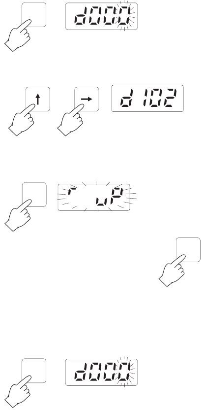
1.A.1 Press DIAG. The display will show the last diagnostic
mode and the right-most numerical digit will blink.
Note If the analyzer has been reset or turned on, “d000” will ap-
pear when pressing DIAG.
1.A.2 Enter code 104 using the and keys.
1.A.3 Press DIAG; “rc 0” will be displayed and the analyzer
will execute this mode.
1.B To automatically calibrate "FULL" scale
1.B.1 Press DIAG. The display will show the last diagnostic
mode and the right-most numerical digit will blink.
1.B.2 Enter code 105 using the and keys.
DIAG
DIAG
DIAG
34
1.B.3 Press DIAG; “rc 1” will be displayed and the analyzer
will execute this mode calibrating the span value e.g.
1V, 10mV or 100mV.
Microprocessor programming routines will measure and cali-
brate the output limits. This procedure will set the output to
approximately 1% accuracy. Fine tune the recorder output by
following the procedure in step 3.
Step 2
If the 4-20 mA output is used (4 Ω < load < 500 Ω), it is
self-calibrated by selecting the 4-20 mA CAL output with the
recorder output selector DIP switch.
2.A To automatically calibrate "4 mA"
2.A.1 Set the 4-20 mA CAL switch to
ON. Because only one switch
should be on at any one time,
all other switches should be off
while the 4-20 mA CAL switch
is selected.
2.A.2 Press DIAG. The display will show the last diagnostic
mode and the right-most numerical digit will blink.
2.A.3 Enter code 106 using the and keys.
DIAG
DIAG

35
2.A.4 Press DIAG; “rc 4” will be displayed and the analyzer
will execute this mode calibrating the output to 4 mA.
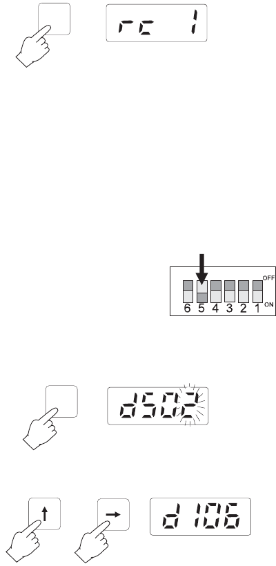
2.B To automatically calibrate "20 mA"
2.B.1 Press DIAG. The display will show the last diagnostic
mode and the right-most numerical digit will blink.
2.B.2 Enter code 107 using the and keys.
2.B.3 Press DIAG; “rc20” will be displayed and the analyzer
will execute this mode calibrating the output to 20 mA.
2.B.4 Using the recorder output selector switches, turn the
Calibrate Current switch off (#5) and then turn the 4-
20mA on (#4).
DIAG
DIAG
DIAG
36
Earth
Ground
Out
Recorder
Output
This procedure will set the output to 1%. Fine tune the re-
corder output by following the procedure in step 3.
Step 3
If the recorder output needs fine tuning, use
the diagnostic routines described below.
• Set the DIP switch to the desired option:
0-10mV/100mV/1V or 4-20 mA.
• Connect a voltmeter, milliammeter or mul-
timeter to the recorder output terminals in
the following sequence:
If output is VOLTAGE
– GROUND output terminal to GROUND input of
multimeter;
– OUT output terminal to VOLTS input of multimeter.
After connections, switch the multimeter to DC VOLTS mode.
If output is CURRENT
– GROUND output terminal to GROUND input of
multimeter;
– OUT output terminal to AMPS input of multimeter.
After connections, switch the multimeter to DC AMPS mode.
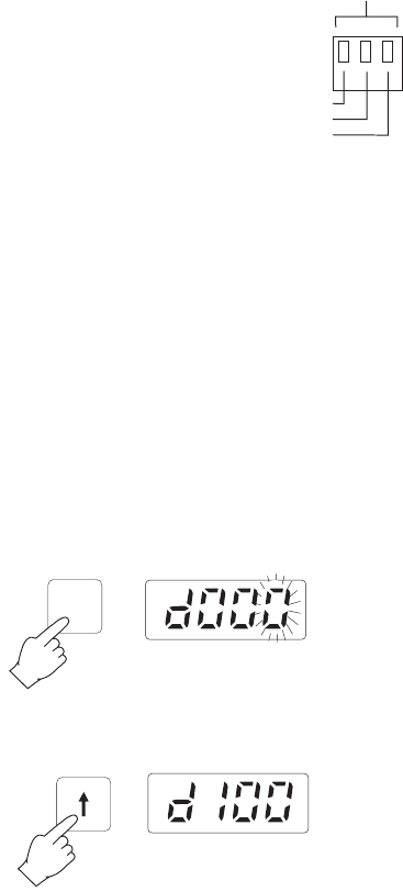
3.A If the recorder zero reads too low
3.A.1 Press DIAG. The display will show the last diagnostic
mode and the right-most numerical digit will blink.
3.A.2 Enter code 100 using the key.
3.A.3 Press DIAG; “r up” will be displayed and the analyzer
will execute this mode fine tuning the low value.
DIAG
37
DIAG
3.A.4 The reading on multimeter will slowly in-
crease. When the desired value is
reached, press DIAG again to store it
and quit the mode.
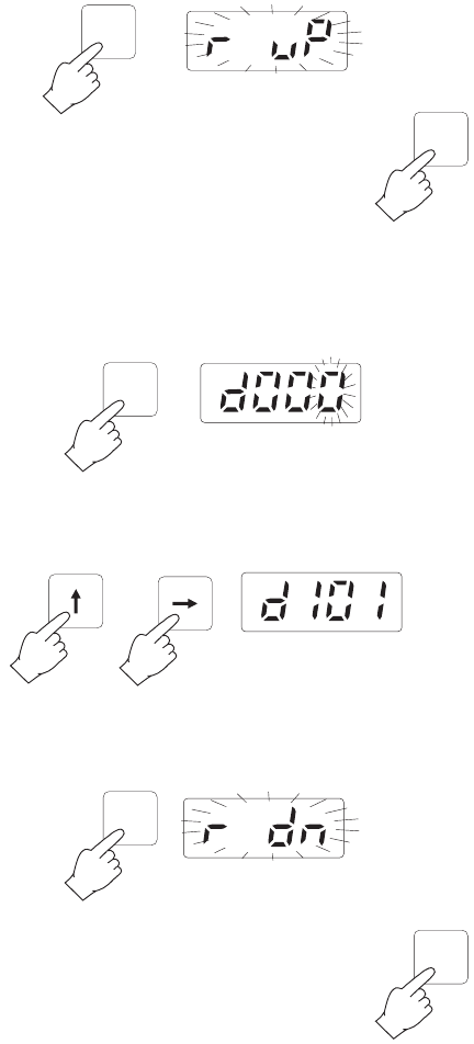
3.B If the recorder zero reads too high
3.B.1 Press DIAG. The display will show the last diagnostic
mode and the right-most numerical digit will blink.
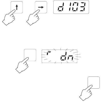
3.B.2 Enter code 101 using the and keys. After code is
selected display will show “d101”.
3.B.3 Press DIAG; “r dn” will be displayed and the analyzer
will execute this mode fine tuning the low value.
3.B.4 The reading on multimeter will slowly de-
crease. When the desired value is
reached, press DIAG again to store it
and quit the mode.
DIAG
DIAG
DIAG
DIAG
38
DIAG
3.C If the recorder full scale (upper limit) reads too
low
3.C.1 Press DIAG. The display will show the last diagnostic
mode and the right-most numerical digit will blink.
3.C.2 Enter code 102 using the and keys.
3.C.3 Press DIAG; “r up” will be displayed and the analyzer
will execute this mode fine tuning upper value.
3.C.4 The reading on multimeter will slowly
increase. When the desired value is
reached, press DIAG again to store it
and quit the mode.
3.D If the recorder full scale (upper limit) reads too
high
3.D.1 Press DIAG. The display will show the last diagnostic
mode and the right-most numerical digit will blink.
DIAG
DIAG
DIAG
39
DIAG
3.D.2 Enter code 103 using the and keys.
3.D.3 Press DIAG; “r dn” will be displayed and the analyzer
will execute this mode fine tuning upper value.
3.D.4 The reading on multimeter will slowly
decrease. When the desired value is
reached, press DIAG again to store it
and quit the mode.
DIAG
40
DIAG
Earth
Ground
Out
Recorder
Output
RECORDER OUTPUT LIMITS CHECK
At any time, it is possible to see on a multimeter the present
settings of the recorder output, e.g. 0-1mV, 4-20 mA etc.
This feature is particularly useful to check
the settings and to ensure the outputs are
functioning.
• Set the DIP switch to the desired option:
0-10mV/100mV/1V or 4-20 mA.
• Connect a voltmeter, milliammeter or mul-
timeter to the recorder output terminals
with the following sequence:
If output is VOLTAGE
– GROUND output to GROUND input of
multimeter;
– OUT output to VOLTS input of multimeter.
After connections, switch the multimeter to DC VOLTS mode.
If output is CURRENT
– GROUND output to GROUND input of
multimeter;
– OUT output to AMPS input of multimeter.
After connections, switch the multimeter to DC AMPS mode.
To see the current minimum recorder output limit
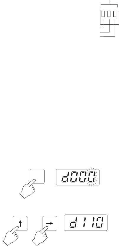
1.A Press DIAG. The display will show the last diagnostic
mode and the right-most numerical digit will blink.
1.B Enter code 110 using the and keys.
1.C Press DIAG; “— —” will be displayed and the analyzer

41
DIAG
DIAG
DIAG
DIAG
DIAG
DIAG
and the multimeter will display the current minimum
recorder output limit.
1.D Press DIAG again to quit the mode.
To see the current maximum recorder output limit
2.A Press DIAG. The display will show the
last diagnostic mode and the right-most numerical digit
will blink.
2.B Enter code 111 using the and keys.
2.C Press DIAG; “— —” will be displayed and the analyzer
and the multimeter will display the current maximum
recorder output limit.
2.D Press DIAG again to quit the mode.
To see the current mid-range recorder output
3.A Press DIAG. The display will show the last diagnostic
mode and the right-most numerical digit will blink.
42
DIAG
DIAG
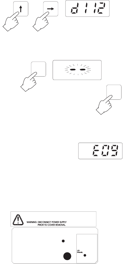
3.B Enter code 112 using the and keys.
3.C Press DIAG; “– –” will be displayed and the analyzer
and the multimeter will display the current mid-range
recorder output limit.
3.D Press DIAG again to quit the mode.
ADJUSTING THE LIGHT SOURCE
If the sample blank is highly colored or turbid, the light level
may be inadequate for a proper operation. This situation is
indicated by the activation of the ana-
lyzer system alarm relay and the
appearance of “E09” on the display.
Note This condition can also be caused by failure of the LED light
source.
It may be possible to compensate for inadequate light level
by adjusting the light source intensity, through the small ac-
cess holes provided. It is not necessary to disassemble the
plastic enclosure to access this trimmer.
43
DIAG
DIAG
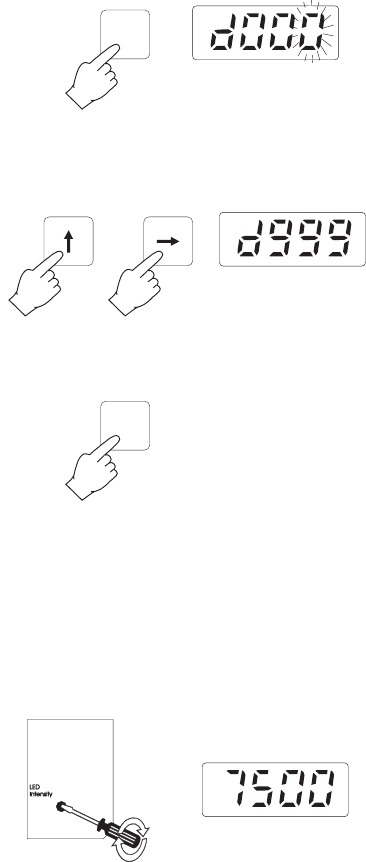
To adjust the light level of the blank sample:
1. Press DIAG. The display will show the last diagnostic mode
and the right-most numerical digit will blink.
2. Enter code 999 using the and keys. After the code is
selected display will show “d999”.
3. Press DIAG to execute the light level set mode. All the
display digits will blink.
4. The display will show direct reading of the photodetector
cell.
5. Make sure the photometric chamber is well flushed. Stop
the external sample stream from flowing into the system.
The photometric cell is now filled with blank sample solu-
tion.
6. Adjust the trimmer on the power supply board to obtain
a reading between 7300 and 7700.
7. Press any key to leave this mode.
44
MAINTENANCE
CALIBRATION REQUIREMENT
Calibration of the PCA 300 and PCA 301 series of Chlo-
rine Analyzers is not normally required. The DPD technique
for measuring Chlorine concentration is well established and
consistent. Also, by measuring the sample blank absorbancy
to establish the zero reference with each measurement, the
accuracy of the analyzer is assured.
If, for any reason, the Chlorine measurements are inaccurate
proceed with the calibration procedure (see page 48).
HYDRAULIC SYSTEM
A visual check of the hydraulic compartment can detect leaks,
pump tubing fatigue or breakage.
These periodic checks help ensure reliable analyzer perfor-
mance.
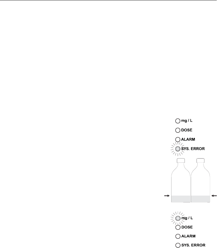
If a pump tube is interrupted and the
reagents are not added to the sample,
the system error LED and relay will be
activated to notify the user.
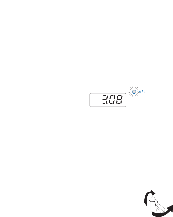
REAGENTS SUPPLY
PCA 300 and PCA 301 warn the user
when the reagents level reaches ap-
proximately 20%.
The green LED (mg/L) will start blink-
ing and, working at maximum capacity
(5 minutes sampling rate), the analyz-
ers can operate for 4 more days.
The alarm system is based on an in-
ternal counter that has to be reset every
time the reagents are replaced.
The counter keeps track of the number
of measurements taken and informs the user when it reaches
the 8640th sample.
45
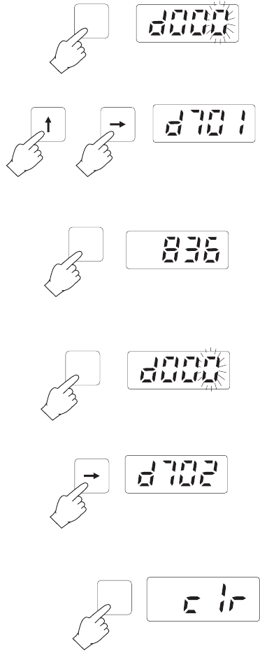
To see the current value, press DIAG. The display will show
the last diagnostic mode and the right-most numerical digit
will blink.
Enter code 701 using the and keys.
Press DIAG and the number of measurements taken will be
displayed in tens (e.g. 8363 will be displayed as 836).
To reset the counter, press DIAG. The display will show the
last diagnostic mode and the right-most numerical digit will
blink.
Enter code 702 using the and keys.
Press DIAG; “clr” will be displayed and the analyzer will zero
the counter.
DIAG
DIAG
DIAG
DIAG
46
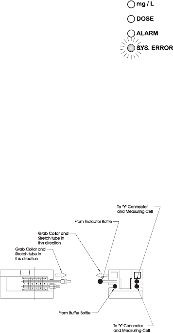
Once reagents are completely ex-
hausted, the system error LED will lit
(while the relay remains activated) to
notify the user.
CHANGING PERISTALTIC PUMP TUBING
It is recommended that the peristaltic pump tubes be changed
on a regular basis depending on sampling period and oper-
ating time.
For a 5 minutes sample interval and continuous operation,
changing of the tubes every month is recommended.
For best results however, change the tubings every time the
reagents are replaced.
Important Note Rubber gloves and eye protection must be worn while han-
dling reagent tubing to prevent contact with reagent chemi-
cals. Read MSDS documents before proceeding.
Grasp the plastic collar of one pump tube and pull the fitting
away from the pump toward the front of the case until it clears
the retaining indentation.
Then move the fitting sideways away from the pump until the
tube clears the slot.
Release the tube and fitting.
The fitting on the other end of the pump tube may now be
easily removed from the pump body.
Remove the reagent tubing from one end of the pump tube
fitting and pull the pump tube from behind the pump rollers.
Replace the pump tube with a new one and reassemble in
reverse order. Repeat for the other pump tube.
47
TUBING REPLACEMENT
The remaining tubing in the analyzers should be replaced
every two months.
When installing new tubing it is helpful to dip them in hot
water before making the connections.
It is also recommended that one tube at a time is removed
and replaced.
Note DPD reagent tubing may darken before the scheduled
replacement time, but this will not affect the instrument’s
performance.
CLEANING MEASUREMENT CELL
In order to maintain the maximum reliability of measurements,
it is recommended to periodically clean the measurement cell.
In fact, the measurement cell could collect sediment or de-
velop a film growth on the inside walls.
Thorough cleaning with a dilute acid solution and a cotton
swab is recommended monthly. Depending on sample con-
ditions at individual locations and absence of input filters,
it may be necessary to clean the cell on a weekly basis.
This can be determined by observing the cell condition
when reagents are changed.
It is also highly recommended to clean the cell every time
you turn the meter off. In such a way, scaling and molds
growth are prevented. Otherwise, subsequent cleaning
might become more difficult.
For cleaning procedure, remove the plastic cap placed on
the top of the measuring cell.
Add a few drops of 19.2N Sulfuric Acid solution or alcohol
to the cell.
Allow sulfuric acid to stand in the measuring cell for 15
minutes to dissolve any foreign materials adhering to the
cell walls. Wipe the cell interior with a cotton-tipped swab.
After wiping, open the drain port to empty the measuring cell
from the cleaning solution.
48
DIAG
RELAY TEST
In the relay test mode all three alarm relays close for about
one second.
1. Press DIAG . The display will show the last diagnostic
mode and the right-most numerical digit will blink.
2. Enter code 501 using the and keys. After the code is
selected display will show “d501”.
3. Press DIAG. The display will blink “ON” and “OFF”, then
the display will automatically return to the last concentra-
tion reading.
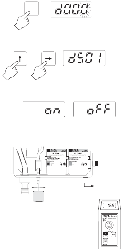
CALIBRATION PROCEDURE
1. Withdraw a sample of the measured liquid direct from the
drain port of the measuring cell (#11) by opening its valve
(#12).
Note: withdraw the sample just before the electrovalve
stops the liquid flow to the measuring cell.
2. With a calibrated meter take a measure of
the sample. This is the calibration value.
49
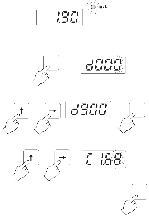
3. Wait for the PCA to display the reading.
4. Press DIAG. The display will show the last diagnostic mode
and the right-most numerical digit will blink.
5. Enter code 900 using the and keys and press DIAG.
6. Enter the calibration value using the and keys.
7. Press DIAG to confirm the value. The dis-
play will show “Stor” for a short time indi-
cating that the new calibration value is stored.
The unit will return to normal operation dis-
playing the calibrated value. Value displayed
can differ on the right most numerical digit.
Note: it is not recommended to calibrate the meter at values below
2 mg/L in order to maintain enough accuracy in the whole
range. Calibration below 2 mg/L does not guarantee de-
clared accuracy outside an interval of ±50% from the cali-
bration value.
DIAG
DIAG
DIAG
50
ERROR CODES
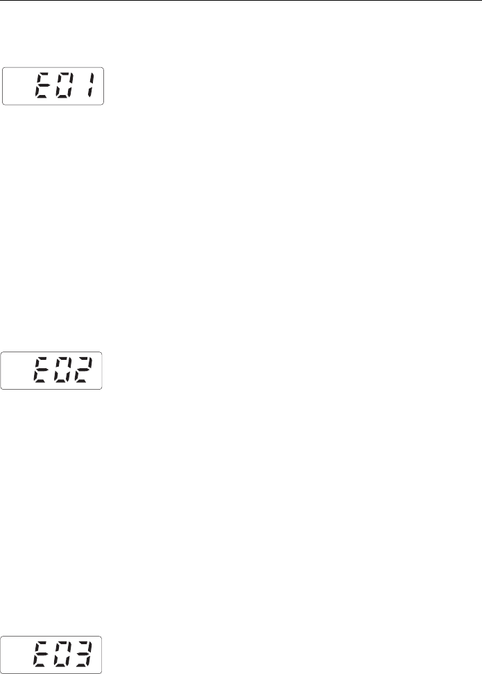
ERROR 0 - NO ERROR
ERROR 1- INVALID LOW-SCALE ADJUSTMENT OF RECORDER OUTPUT
1. The manual (fine) low-scale adjustment of the recorder
output in the DOWN direction (DIAG 101) could not be
performed.
2. The automatic low-scale adjustment of the recorder out-
put in the DOWN direction (DIAG 104 or 106) could
not be performed.
Check the dip switches for proper configuration.
Also, when in DIAG 101, “E01” can occur if the user does
not press DIAG again before the displayed DVM reading
goes below:
a. 100 mV, with 0-1 V dip switch setting
b. 10 mV, with 0-100 mV dip switch setting
c. 1 mV, with 0-10 mV dip switch setting.
Another possibility is hardware failure.
ERROR 2 - INVALID FULL-SCALE ADJUSTMENT OF RECORDER OUTPUT
1. The manual (fine) full-scale adjustment of the recorder
output in the UP direction (DIAG 102) could not be per-
formed.
2. The automatic full-scale adjustment of the recorder out-
put in the DOWN direction (DIAG 105 or 107) could
not be performed.
Check the dip switches for proper configuration.
Also, when in DIAG 102, “E02” can occur if the user does
not press DIAG again before the displayed DVM reading
goes above:
a. 1.1 V, with 0-1 V dip switch setting
b. 110 mV, with 0-100 mV dip switch setting
c. 11 mV, with 0-10 mV dip switch setting.
Another possibility is hardware failure.
ERROR 3 - INVALID LOW-SCALE ADJUSTMENT OF RECORDER OUTPUT
The manual (fine) low-scale adjustment of the recorder
output in the UP direction (DIAG 100) could not be per-
formed.

51
Check the dip switches for proper configuration.
Also, when in DIAG 100, “E03” can occur if the user does
not press DIAG again before the displayed DVM reading
goes above:
a. 100 mV, with 0-1 V dip switch setting
b. 10 mV, with 0-100 mV dip switch setting
c. 1 mV, with 0-10 mV dip switch setting.
Another possibility is hardware failure.
ERROR 4 - INVALID FULL-SCALE ADJUSTMENT OF RECORDER OUTPUT
The manual (fine) full-scale adjustment of the recorder out-
put in the DOWN direction (DIAG 103) could not be
performed.
Check the dip switches for proper configuration.
Also, when in DIAG 103, “E04” can occur if the user does
not press DIAG again before the displayed DVM reading
goes below:
a. 0.9 V, with 0-1 V dip switch setting
b. 90 mV, with 0-100 mV dip switch setting
c. 9 mV, with 0-10 mV dip switch setting.
Another possibility is hardware failure.
ERROR 5 - INVALID VALUE
The user attempted to set a sampling rate out of range (5
to 90 minutes).
ERROR 6 - INVALID VALUE
The user attempted to set one of the following above
5.00 mg/L:
1. recorder min/max;
2. alarm setpoint;
3. proportional dosing setpoint.
ERROR 7 - INVALID VALUE
The user attempted to set REC.MIN at a higher value than
REC.MAX.
52
ERROR 8 - LOW ABSORPTION
The measured absorption is too low. Possible reasons in-
clude:
1. empty reagent bottles;
2. clogged, pinched or broken tubes;
3. interrupted sample flow.
ERROR 9 - LOW BLANK READING
If the sample blank is highly colored or turbid, the light
level may be inadequate for a proper operation. This situ-
ation is indicated by the activation of the analyzer system
alarm relay and the appearance of “E09” on the display.
This condition can also be caused by failure of the LED
light source.
ERROR 10 - HIGH BLANK READING
Possible reason is optical LED brightness (DIAG 999) too
high.
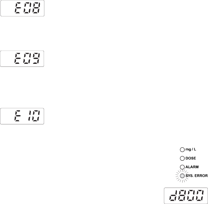
Note Error codes E01 to E07 are displayed on the analyzer but
do not cause a system error condition.
Error codes E08 to E10 are not displayed
but cause the SYS.ERROR LED to turn on
and the corresponding relay to close.
To view these error codes, enter code
800.

53
OPERATIONAL & DIAGNOSTIC CODES
Code Function
100 Increase recorder output lower limit in manual
low-scale adjustment
101 Decrease recorder output lower limit in
manual low-scale adjustment
102 Increase recorder output upper limit in
manual full-scale adjustment
103 Decrease recorder output upper limit in
manual full-scale adjustment
104 Set recorder 0 V automatically with dip
switch setting at 0-1 V, 0-100 mV or
0-10 mV
105 Set recorder full-scale automatically with
dip switch setting at 0-1 V, 0-100 mV or
0-10 mV
106 Set recorder 4 mA automatically with dip
switch setting at calibrate current
107 Set recorder 20 mA automatically with dip
switch setting at calibrate current
110 Show recorder output low-scale setting on
DVM or ammeter
111 Show recorder output full-scale setting on
DVM or ammeter
112 Show recorder output mid-range value on
DVM or ammeter
400 Set delta of proportional dosing
401 Show current delta of proportional dosing
500 LED’s test; momentarily turn on all display
LED segments, mg/L LED, dosing LED,
alarm LED and system error LED
501 Alarm relay test; momentarily energize dos-
ing relay, alarm relay and system error
relay
502 Prime peristaltic pump for 3 minutes or
until user presses the DIAG key

54
503 Clear previous minimum/maximum concen-
tration values
700 Set the display brightness level
701 Show the current reagent counter value (in
tens)
702 Reset the reagent counter
710 Set the alarm logic (low or high)
711 Show the current alarm logic
800 Show the last system error message (E08
to E10)
900*Show the current value and allow calibra-
tion to a new value
901*Show the calibration factor (0.00 to 1.00)
902*Reset the calibration factor to 1.00
999 Adjust optical LED light intensity
*Diagnostic codes reserved to technical personnel only.

55
INTERFACE WITH PC (PCA 300 and PCA 301 only)
A serial interface permits the PCA 300 and PCA 301 to
have direct connection with a computer. Connection with
a computer allows collecting, storing or printing of the
sample concentration data.
Data transmission from the instruments to the
PC is possible with the HI92000 Windows®
compatible application software offered by
Hanna Instruments.
Refer to the drawing for proper wire connec-
tions.
Serial port set up is: 1200 baud, no parity, 8 bits per byte,
one stop bit (can not be changed by the operator).
A simple example written in Microsoft QBASIC shows how
to read/print concentration data from the analyzer:
OPEN “COM1: 1200,N,8,1,CD0,CS0,DS0,OP0,RS,
TB2048,RB2048” FOR RANDOM AS #1
CLS
PRINT #1, “1” ‘INITIALIZE PORT 1
COM(1) ON ‘ENABLE EVENT TRAPPING
‘ON PORT 1
ON COM(1) GOSUB ComHandler
‘PROVIDE INTERRUPT NAME
DO: LOOP WHILE INKEY$ <> “ “
‘LOOP UNTIL ANY KEY IS
‘PUSHED, THEN EXIT
COM(1) OFF
END
ComHandler:
‘INTERRUPT SUBROUTINE TO
‘PRINT THE VALUE
INPUT #1, value$
PRINT “Chlorine concentration is :”, value$
RETURN
Note In PCA300A, PCA300AC, PCA301A and PCA301AC models
the RS232 terminal is not used / not connected.

56
ACCESSORIES
ChecktempC Termometer (-50.0 to 150.0 ºC)
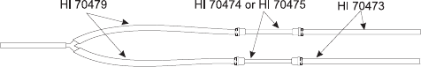
HI 70473 Complete kit of tubes from pressure regulator to drain
HI 70474 Peristaltic pump tube (6 pcs)
HI 70475 Peristaltic pump tube (2 pcs)
HI 70476 Reagent bottle inside tube (6 pcs)
HI 70477 Y strainer and line tube from Y strainer to cell (6 pcs)
HI 70478 Tube from bottle to pump (6 pcs)
HI 70479 Tube from pump to Y strainer (6 pcs)
HI 70480 Free Cl2 Reagent Pack (HI 70450, HI 70451 and HI 70452)
HI 70481 Total Cl2 Reagent Pack (HI 70460, HI 70461 and HI 70452)
HI 70482 0.5/50 micron filter system
HI 70483 Complete kit of reagent tubing spare kit (2 pcs)
HI 70484 Complete kit of reagent tubing spare kit (6 pcs)
HI 70485 Cuvet stirrer motor
HI 70486 Stirring bar (5 pcs)
HI 70487 Colorimetric cell
HI 70488 Electrovalve (24 VAC/60 Hz)
HI 70489 Electrovalve (24 VAC/50 Hz)
HI 92000 Windows Compatible Application Software

57
WARRANTY
All Hanna Instruments meters are guaranteed for two
years against defects in workmanship and materials when
used for their intended purpose and maintained accord-
ing to instructions.
This warranty is limited to repair or replacement free of
charge.
Damage due to accident, misuse, tampering or lack of
prescribed maintenance are not covered.
If service is required, contact the dealer from whom you
purchased the instrument. If under warranty, report the
model number, date of purchase, serial number and the
nature of the failure. If the repair is not covered by the
warranty, you will be notified of the charges incurred. If the
instrument is to be returned to Hanna Instruments, first ob-
tain a Returned Goods Authorization number from the
Customer Service department and then send it with ship-
ping costs prepaid. When shipping any instrument, make
sure it is properly packaged for complete protection.
All rights are reserved. Reproduction in whole or in part
is prohibited without the written consent of the copy-
right owner.
Hanna Instruments reserves the right to modify the design,
construction and appearance of its products without advance
notice.

58
OTHER PRODUCTS FROM HANNA
• CALIBRATION AND MAINTENANCE SOLUTIONS
• CHEMICAL TEST KITS
• CHLORINE METERS
• CONDUCTIVITY/TDS METERS
• DISSOLVED OXYGEN METERS
• HYGROMETERS
• ION SPECIFIC METERS (Colorimeters)
• MAGNETIC STIRRERS
• Na/NaCl METERS
• pH/ORP/Na ELECTRODES
• pH METERS
• PROBES (DO, µS/cm, RH, T, TDS)
• PUMPS
• REAGENTS
• SOFTWARE
• THERMOMETERS
• TITRATORS
• TRANSMITTERS
• TURBIDITY METERS
• Wide Range of Accessories
Most Hanna meters are available in the following formats:
• BENCH-TOP METERS
• POCKET-SIZED METERS
• PORTABLE METERS
• PRINTING/LOGGING METERS
• PROCESS METERS (Panel and Wall-mounted)
• WATERPROOF METERS
• METERS FOR FOOD INDUSTRY
For additional information, contact your dealer or the near-
est Hanna Customer Service Center.
You can also e-mail us at tech@hannainst.com.
59
CE DECLARATION OF CONFORMITY
Recommendations for Users
Before using these products, make sure that they are entirely suitable for the environment in which they are
used.
Operation of these instruments in residential areas could cause unacceptable interference to radio and TV
equipment.
Any variation introduced by the user to the supplied equipment may degrade the instruments' EMC
performance.
Unplug the instruments from power supply before opening the front cover.

www.hannainst.com
MANPCA300R1
07/02
PCA300 AND PCA301 COMPLIANCE MARKS
