Hans Turck and KG TN902-Q175L201 UHF RFID read/write device User Manual
Hans Turck GmbH & Co. KG UHF RFID read/write device
user manual
© Hans Turck GmbH & Co. KG | D500049 2015-09 DE FR EN
130
120
60
M12
LED
200
175
60
M12
LED
20...50 cm
Europe max. 3,5 m
USA, China max. 4,0 m
min. 50 cm
min. 50 cm
metal
ground
liquid
M6 x 12
M6 x 12
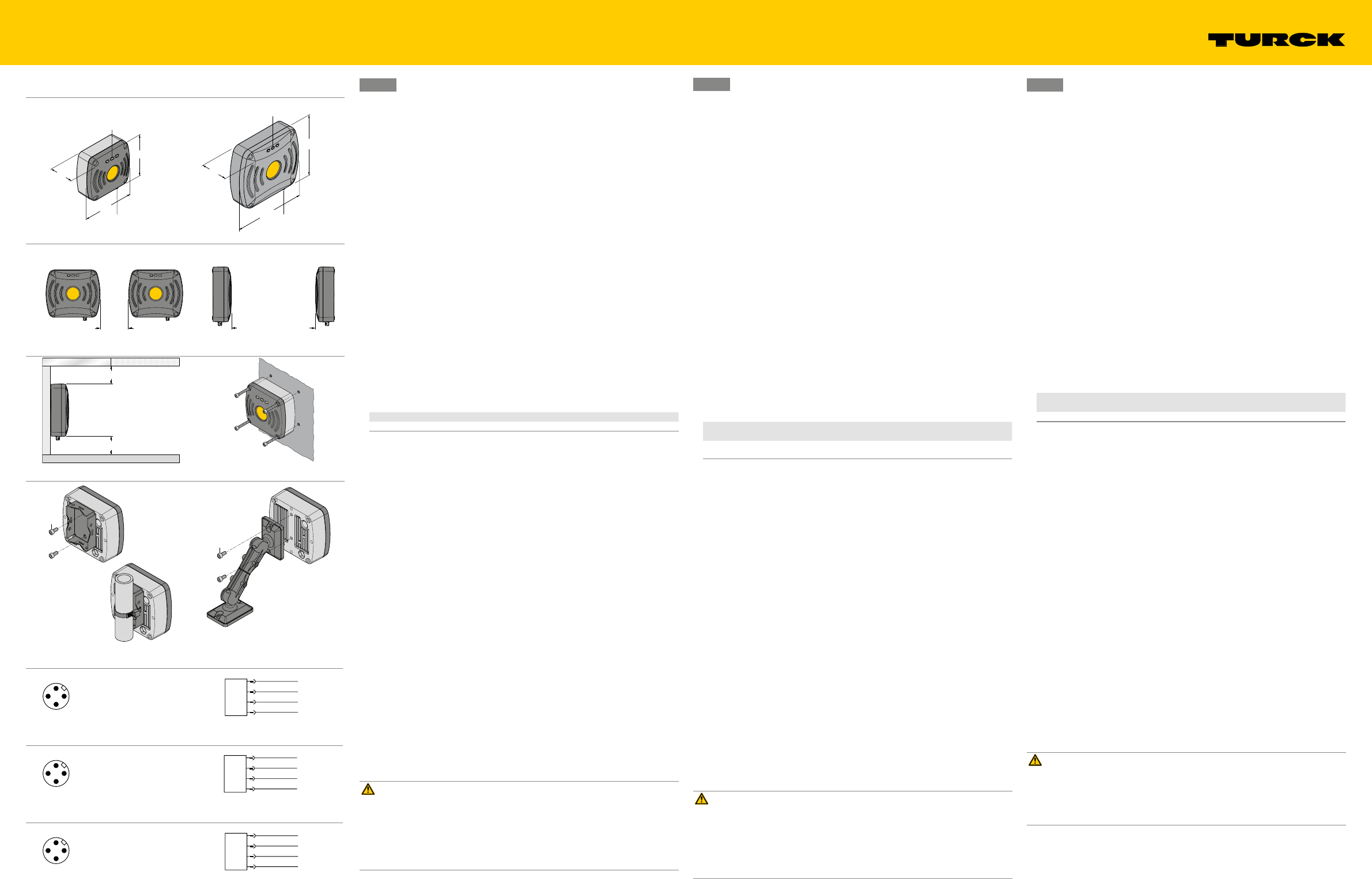
Wiring Diagrams
Connectors …/S2500
Connectors …/S2501
Connectors …/S2503
TN902-…-H1147
UHF-Schreib-Lese-Köpfe TN902-Q…L…-H1147
Weitere Unterlagen
Ergänzend zu diesem Dokument finden Sie im Internet unter www.turck.com folgende
Unterlagen:
■Datenblatt
■Projektierungshandbuch RFID
■Inbetriebnahmehandbücher
■Anwenderhandbücher für die Software-Tools RDemo und WebConfig
■Gerätezulassungen
Zu Ihrer Sicherheit
Bestimmungsgemäße Verwendung
Die Geräte sind für den Einbau in industrielle Großanlagen und Großwerkzeuge bestimmt und
für Anwendungen in der industriellen Automation vorgesehen.
Die BL ident®-UHF-Schreib-Lese-Köpfe dienen zum berührungslosen Datenaustausch mit den
BL ident®-Datenträgern im BL ident®-UHF-RFID-System. Durch Einflussgrößen wie Bauteilto-
leranzen, Einbausituationen, Umgebungsbedingungen und Materialien (insbesondere Metall
und Flüssigkeiten) können die jeweils erreichbaren Schreib-Lese-Abstände varieren. Darum
ist ein Test der Applikation (vor allem beim Lesen und Schreiben in der Bewegung) unbedingt
erforderlich. Der Betrieb der Geräte ist nur in Ländern erlaubt, in denen ein Frequenzbereich
902…928 MHz für die Nutzung von passivem UHF-RFID freigegeben ist.
Die Geräte dürfen nur wie in dieser Anleitung beschrieben verwendet werden. Jede andere
Verwendung gilt als nicht bestimmungsgemäß; für daraus resultierende Schäden übernimmt
TURCK keine Haftung.
Allgemeine Sicherheitshinweise
■Nur fachlich geschultes Personal darf das Gerät montieren, installieren, betreiben und
instand halten.
■Ein längerer Aufenthalt im Strahlungsbereich der UHF-Schreib-Lese-Köpfe kann gesund-
heitsschädlich sein. Mindestabstände zur aktiv ausstrahlenden Fläche des Schreib-Lese-
Kopfs einhalten.
Region max. zulässige Strahlungsleistung Sicherheitsabstand
USA/Kanada 4 W EIRP > 0,30 m
■Die Strahlung der UHF-Schreib-Lese-Köpfe kann medizinische Hilfsmittel beeinflussen.
Erhöhten Abstand zu aktiven Strahlungsquellen bis hin zur maximalen Sendereichweite
einhalten.
Produktbeschreibung
Geräteübersicht
Siehe Abb. 1 (TN902-Q120L130-H1147) und Abb. 2 (TN902-Q175L200-H1147).
Funktionen und Betriebsarten
Die UHF-Schreib-Lese-Köpfe TN902-… arbeiten mit integrierter Antenne in einem Frequenz-
bereich von 902…928 MHz. Mit den Geräten können passive UHF-Datenträger im Single- und
Multi-Tag-Betrieb ausgelesen und beschrieben werden. Dazu bilden die Geräte eine Übertra-
gungszone aus, deren Größe und Ausdehnung u. a. von den verwendeten Datenträgern und
den Einsatzbedingungen der Applikation abhängig sind. Die maximalen Schreib-Lese-Abstän-
de sind in den Datenblättern aufgeführt. Die Geräte lassen sich mit Softwaretools über einen
PC umfassend testen, konfigurieren und parametrieren.
Montieren
Die Geräte können in beliebiger Ausrichtung montiert werden.
Montieren Sie das Gerät mit dem zugehörigen Befestigungszubehör.
Wählen Sie als Minimalabstand zwischen zwei Schreib-Lese-Köpfen mindestens 20 cm,
besser ist ein Abstand von 50 cm (Abb. 3).
Wählen Sie bei Portal-Konfigurationen (Abb. 4) einen Abstand von mindestens 3,5 m.
Halten Sie bei der Montage einen Mindestabstand von 50 cm zwischen Schreib-Lese-Kopf
und Boden, Flüssigkeiten sowie Metallen ein (Abb. 5).
Aufschrauben auf Montageplatte
Montieren Sie das Gerät gemäß Abb. 6.
Mast- und Rohrmontage
Montieren Sie das Gerät gemäß Abb. 7.
Montieren mit Befestigungsarm
Der Befestigungsarm RH-Q240L280/Q280L640 (Ident-Nr. 7030296) ist nicht im Lieferumfang
enthalten.
Montieren Sie das Gerät gemäß Abb. 8.
Anschließen
GEFAHR
Beeinflussung elektrisch gesteuerter medizinischer Hilfsmittel wie Herzschrittmacher
Lebensgefahr durch Störung oder Ausfall medizinischer Hilfsmittel
Informieren Sie sich, inwiefern die eingesetzte Strahlungsstärke Ihre medizinischen
Hilfsmittel beeinflusst.
Informieren Sie sich über die für Ihr eingesetztes Hilfsmittel zulässigen Abstände zu
Strahlungsquellen.
Halten Sie erhöhten Abstand zu aktiven Strahlungsquellen bis hin zur maximalen Sende-
reichweite der Strahlungsquelle.
Schließen Sie das Gerät über den M12-Steckverbinder an das BL ident®-Interface an.
In Betrieb nehmen
Nach Anschluss der Leitungen und Aufschalten der Versorgungsspannung geht das Gerät
automatisch in Betrieb.
DE Kurzbetriebsanleitung
TN902-Q…L…-H1147 UHF read/write heads
Other documents
Besides this document the following material can be found on the Internet at www.turck.com:
■Data sheet
■RFID engineering manual
■Startup manuals
■User manuals for the RDemo and WebConfig software tools
■Device approvals
For your safety
Intended use
The devices are designed for installation in large-scale industrial plants and equipment and for
use in industrial automation applications.
The BL ident® UHF read/write heads are used for contactless data exchange with the BL ident®
tags in the BL ident® UHF RFID system. The possible read/write distances may vary according to
factors such as component tolerances, mounting locations, ambient conditions and the effect
of materials (particularly metal and liquids). For this reason, the application must be tested in all
cases under real conditions (particularly with read and write operations in motion). The devices
can only be operated in countries in which a frequency of 902…928 MHz is permitted for the
use of passive UHF-RFID.
The devices must only be used as described in these instructions. Any other use is not in accor-
dance with the intended use; TURCK accepts no liability for any resulting damage.
General safety notes
■The device must only be fitted, installed, operated and maintained by trained and qualified
personnel.
■Any extended stay within the area of radiation of the UHF read/write heads may be harmful
to health. Observe minimum distances from the actively radiating surface of the read/write
head.
Region max. permissible total radiant
output power Safety distance
USA/Canada 4 W EIRP > 0.30m
■The radiation of the UHF read/write heads may impair the operation of medical equipment.
Keep an additional distance from active radiation sources up to the maximum transmission
distance.
Product description
Device overview
See Fig. 1 (TN902-Q120L130-H1147) and Fig. 2 (TN902-Q175L200-H1147).
Functions and operating modes
The TN902-… UHF read/write heads operate with an integrated antenna in a frequency range
of 902…928 MHz. The devices enable passive UHF tags to be read or written in single and
multi-tag operation. For this the devices form a transmission zone that varies in size and range
according to the tags used and the operating conditions of the application. Refer to the data
sheets for the applicable maximum read/write distances. The devices can be extensively tested,
configured and parameterized from a PC using the specified software tools.
Mounting
The devices can be mounted in any position.
Mount the device with the associated fixing accessories.
Select 20 cm between two read/write heads, a distance of 50 cm is recommended (Fig. 3).
With portal configurations (Fig. 4) choose a distance of at least 3.5 m.
Keep a minimum distance of 50 cm between a read/write head and the ground, liquids or
metals (Fig. 5).
Screw fastening on a mounting plate
Mount the device as per Fig. 6.
Mast/tube mounting
Mount the device as per Fig. 7.
Mounting with mounting bracket
The RH-Q240L280/Q280L640 mounting bracket (Ident no. 7030296) is not supplied with the
device.
Mount the device as per Fig. 8.
Connection
DANGER
Effect on electrically controlled medical devices such as pacemakers
Danger to life due to malfunction or failure of medical equipment
Find out the extent to which the radiation strength of your medical devices is affected.
Find out the permissible distances from radiation sources for the devices you are using.
Keep an additional distance from active radiation sources up to the maximum transmis-
sion distance of the radiation source.
Connect the device via the M12 connector to the BL ident® interface.
Commissioning
The device is operational automatically once the cables are connected and the power supply is
switched on.
EN Quick-Start Guide
Têtes de lecture-écriture UHF TN902-Q…L…-H1147
Documents supplémentaires
Sous www.turck.com vous trouverez les documents suivants, qui contiennent des informations
complémentaires au présent document:
■Fiche technique
■Manuel de détermination RFID
■Manuels de mise en service
■Manuels utilisateur pour les outils logiciels RDemo et WebConfig
■Homologations appareils
Pour votre sécurité
Application correcte
Les appareils sont conçus pour une intégration au sein d’installations et d’outils industriels de
grandes dimensions et pour des applications d’automatisation industrielle.
Les têtes de lecture-écriture UHF BL ident® servent à l’échange de données sans contact
avec les support de données BL ident® dans le système RFID-UHD BL ident®. En raison de
facteurs d’influence comme les tolérances des composants, les emplacements de montage,
les conditions ambiantes et les matériaux (en particulier le métal et les liquides), les distances
accessibles d’écriture-de lecture peuvent varier. Voilà pourquoi il est indispensable d’effectuer
un test de l’application (surtout pour la lecture et l’écriture en mouvement). Le fonctionnement
des appareils est uniquement autorisé dans les pays dans lesquels une plage de fréquence de
902-908 MHz est autorisée pour l’utilisation de RFID-UHD passif.
Les appareils peuvent exclusivement être utilisés conformément aux indications figurant dans
cette notice. Toute autre utilisation est considérée comme non conforme ; la société TURCK
décline toute responsabilité en cas de dommages causés par une utilisation non conforme.
Consignes générales de sécurité
■Seul un personnel spécialement formé peut monter, installer, exploiter et effectuer la main-
tenance de l’appareil.
■Une exposition prolongée dans la zone de rayonnement des têtes de lecture-écriture
UHF peut avoir des conséquences néfastes sur la santé. Respecter les distances minimales
requises par rapport à la surface de rayonnement de la tête de lecture-écriture.
Région Puissance de rayonnement maxi
admise Distance de sécurité
États-Unis/
Canada 4 W EIRP > 0,30 m
■Le rayonnement des têtes de lecture-écriture UHF peut impacter certains dispositifs médi-
caux. Respecter une distance supérieure par rapport aux sources actives de rayonnement
jusqu’à la portée d’émission maximale.
Description du produit
Présentation du produit
Voir fig. 1 (TN902-Q120L130-H1147) et fig. 2 (TN902-Q175L200-H1147).
Fonctions et modes de fonctionnement
Les têtes de lecture-écriture UHF TN902-… fonctionnent avec une antenne intégrée dans une
plage de fréquence comprise entre 902 et 928 MHz. Les appareils permettent d’écrire et de lire
sur les supports de données UHF en mode Single-Tag et Multi-Tag. En outre, les appareils créent
une zone de transmission dont la taille et l’étendue dépendent entre autres des supports de
données utilisés et des conditions d’utilisation de l’application. Les distances maximales de lec-
ture-écriture sont indiquées dans les fiches techniques. Les appareils peuvent être largement
testés, paramétrés et configurés via un PC à l’aide d’outils logiciels.
Montage
Les appareils peuvent être montés dans n’importe quelle direction.
Montez l’appareil avec les accessoires de fixation correspondants.
Choisissez au moins 20 cm comme distance minimale entre deux têtes de lecture-écriture,
préférer plutôt une distance de 50 cm (fig. 3).
Pour les configurations de portail (fig. 4), choisissez une distance de minimum 3,5 m.
Lors du montage, respectez une distance minimale de 50 cm entre la tête de lecture-écriture
et le sol, les fluides et les métaux (fig. 5).
Vissage sur plaque de montage
Fixez l’appareil comme indiqué sur la figure 6.
Montage sur mât et tube
Fixez l’appareil comme indiqué sur la figure 7.
Montage sur bras de xation
Les fixations RH-Q240L280/Q280L640 (n° d’ident. 7030296) ne sont pas fournies.
Fixez l’appareil comme indiqué sur la figure 8.
Raccordement
DANGER
Risque d'effet sur les dispositifs médicaux électriques comme les stimulateurs cardiaques
Risque mortel en raison d'une perturbation ou d'une panne des dispositifs médicaux
Informez-vous sur la manière dont la puissance de rayonnement paramétrée peut impac-
ter votre dispositif médical.
Informez-vous sur les distances à respecter par rapport aux sources de rayonnement en
fonction du dispositif médical que vous portez.
Respectez une distance supérieure par rapport aux sources actives de rayonnement
jusqu'à la portée d'émission maximale de la source de rayonnement.
Raccordez l’appareil via des connecteurs enfichables M12 avec l’interface BL ident®.
FR Guide d’utilisation rapide
Hans Turck GmbH & Co. KG | 45472 Muelheim an der Ruhr | Germany | Witzlebenstraße 7 | Tel. +49 208 4952-0 | Fax +49 208 4952-264 | more@turck.com | www.turck.com © Hans Turck GmbH & Co. KG | D500049 2015-09 DE FR EN
TN902-…-H1147
FCC/IC Digital Device Limitations – TN902-Q120L130-H1147
FCC ID: YQ7TN902-Q120L131
IC ID: 8821A-T902Q12L14
This device complies with Part 15 of the FCC Rules. Operation is subject to the following two
conditions:
(1) this device may not cause harmful interference, and
(2) this device must accept any interference received, including interference that may cause
undesired operation.
Changes or modifications not expressly approved by the party responsible for compliance
could void the user’s authority to operate the equipment.
Le présent appareil est conforme aux CNR d’Industrie Canada applicables aux appareils radio
exempts de licence. L’exploitation est autorisée aux deux conditions suivantes :
(1) l’appareil ne doit pas produire de brouillage, et
(2) l’utilisateur de l’appareil doit accepter tout brouillage radioélectrique subi, même si le
brouillage est susceptible d’en compromettre le fonctionnement.
Note: This equipment has been tested and found to comply with the limits for a Class A
digital device, pursuant to part 15 of the FCC Rules. These limits are designed to
provide reasonable protection against harmful interference when the equipment is
operated in a commercial environment.
This equipment generates, uses, and can radiate radio frequency energy and, if
not installed and used in accordance with the instruction manual, may cause harmful
interference to radio communications. Operation of this equipment in a residential
area is likely to cause harmful interference in which case the user will be required to
correct the interference at his own expense.
This equipment complies with FCC/IC exposure limits set forth for an uncontrolled environ-
ment.
This equipment should be installed and operated with minimum distance 30 cm between the
radiator & your body.
CAN ICES-3 (A)/NMB-3(A)
Use only with listed LPS or class 2 power supply!
FCC/IC Digital Device Limitations – TN902-Q175L200-H1147
FCC ID: YQ7TN902-Q175L201
IC: 8821A-T902Q17L21
This device complies with Part 15 of the FCC Rules. Operation is subject to the following two
conditions:
(1) this device may not cause harmful interference, and
(2) this device must accept any interference received, including interference that may cause
undesired operation.
Changes or modifications not expressly approved by the party responsible for compliance
could void the user’s authority to operate the equipment.
This device complies with Industry Canada licence-exempt RSS standard(s). Operation is sub-
ject to the following two conditions:
(1) this device may not cause interference, and
(2) this device must accept any interference, including interference that may cause
undesired operation of the device.
Le présent appareil est conforme aux CNR d’Industrie Canada applicables aux appareils radio
exempts de licence. L’exploitation est autorisée aux deux conditions suivantes :
(1) l’appareil ne doit pas produire de brouillage, et
(2) l’utilisateur de l’appareil doit accepter tout brouillage radioélectrique subi, même si le
brouillage est susceptible d’en compromettre le fonctionnement.
Note: This equipment has been tested and found to comply with the limits for a Class A
digital device, pursuant to part 15 of the FCC Rules.
These limits are designed to provide reasonable protection against harmful
interference when the equipment is operated in a commercial environment.
This equipment generates, uses, and can radiate radio frequency energy and, if not
installed and used in accordance with the instruction manual, may cause harmful
interference to radio communications. Operation of this equipment in a residential
area is likely to cause harmful interference in which case the user will be required to
correct the interference at his own expense.
This equipment complies with FCC/IC exposure limits set forth for an uncontrolled environ-
ment.
This equipment should be installed and operated with minimum distance 30 cm between the
radiator & your body.
CAN ICES-3 (A)/NMB-3(A)
Use only with listed LPS or class 2 power supply!
Technical features TN902-Q120… TN902-Q175…
Mounting conditions non-flush non-flush
Ambient temperature -25…+50 °C -25…+50 °C
Operating voltage 12…24 VDC 12…24 VDC
Data transfer alternating electromagnetic field alternating electromagnetic field
Operating frequency 902…928 MHz 902…928 MHz
Radio communication
and protocol standards
ISO 18000-6C
EPCglobal Gen 2
ISO 18000-6C
EPCglobal Gen 2
Channel spacing 200 kHz 200 kHz
Output power 0.5 W (ERP), adjustable 1 W (ERP), adjustable
Antenna polarization RHCP RHCP
Antenna HBPW 110° 90°
Read/write distance max. 1500 mm 4000 mm
Output function 4-wire, read/write 4-wire, read/write
Construction rectangular rectangular
Dimensions 130 × 120 × 60 mm 200 × 175 × 60 mm
Housing material Aluminium, AL, silver Aluminium, AL, silver
Material active area plastic, ABS, black plastic, ABS, black
Connection male, M12 × 1 male, M12 × 1
Vibration resistance 55 Hz (1 mm) 55 Hz (1 mm)
Shock resistance 30 g (11 ms) 30 g (11 ms)
IP rating IP67 IP67
MTTF 51 years acc. to SN 29500 (Ed.99)
40 °C
51 years acc. to SN 29500 (Ed.99)
40 °C
Power-on indication LED green/yellow/red LED green/yellow/red
Diagnostic display differently adjustable different settings
Technical Data | Technische Daten | Données techniques
Betreiben
LED-Anzeigen
LED 1 (grün) LED 2 (gelb) LED 3 (rot) Bedeutung
aus aus aus Betriebsspannung ausgeschaltet
weiß leuchtet
dauerhaft weiß leuchtet
dauerhaft weiß leuchtet
dauerhaft Startphase
grün leuchtet
dauerhaft aus aus Betriebsspannung eingeschal-
tet, Funkfeld ausgeschaltet, kein
interner Fehler
grün leuchtet
dauerhaft gelb leuchtet
dauerhaft aus Betriebsspannung eingeschal-
tet, Funkfeld eingeschaltet, kein
interner Fehler
grün leuchtet
dauerhaft gelb leuchtet
dauerhaft rot leuchtet
dauerhaft Betriebsspannung eingeschaltet,
Funkfeld eingeschaltet, interner
Fehler
grün blinkt aus aus Zugriff auf Datenträger erfolg-
reich
grün blinkt gelb leuchtet
dauerhaft aus Datenträger befindet sich im
Funkfeld
Lauflicht: grün > gelb > rot Testmodus
Einstellen und Parametrieren
Die Geräte lassen sich über Software-Tools mit einem PC parametrieren. Weitere Informationen
finden Sie in den BL ident®-Inbetriebnahmehandbüchern.
Reparieren
Das Gerät ist nicht zur Reparatur durch den Benutzer vorgesehen. Sollte das Gerät defekt sein,
nehmen Sie es außer Betrieb. Bei Rücksendung an TURCK beachten Sie bitte unsere Rücknah-
mebedingungen.
Entsorgen
Die Geräte sind für den Einbau in industrielle Großanlagen und Großwerkzeuge bestimmt. Die
Geräte müssen fachgerecht entsorgt werden und gehören nicht in den normalen Hausmüll.
DE Kurzbetriebsanleitung
Operation
LEDs
LED 1 (green) LED 2 (yellow) LED 3 (red) Meaning
off off off Operating voltage switched off
white
continuously lit white
continuously lit white
continuously lit Start phase
green
continuously lit off off Operating voltage switched
on, radio field switched off, no
internal error
green
continuously lit yellow
continuously lit off Operating voltage switched
on, radio field switched on, no
internal error
green
continuously lit yellow
continuously lit red
continuously lit Operating voltage switched on,
radio field switched on, internal
error
green flashing off off
Access to the data areas suc-
cessful
green flashing yellow
continuously lit off Data carrier located in the radio
field
Running light: green > yellow > red Test mode
Setting and parameterization
The devices can be parameterized via software tools with a PC. Further information is provided
in the BL ident® startup manuals.
Repair
The device must not be repaired by the user. The device must be decommissioned if it is faulty.
Observe our return acceptance conditions when returning the device to TURCK.
Disposal
The devices are designed for installation in large-scale industrial installations and equipment.
The devices must be disposed of correctly and must not be included in normal household
garbage.
EN Quick-Start Guide
FR Guide d’utilisation rapide
Mise en marche
Après avoir raccordé les câbles et après mise sous tension, l’appareil se met automatiquement
en marche.
Utilisation
Visualisations par LED
LED 1 (verte) LED 2 (jaune) LED 3 (rouge) signication
éteint éteint éteint Tension de service désactivée
blanc allumé en
fixe blanc allumé en
fixe blanc allumé
en fixe Phase de démarrage
vert allumé en fixe éteint éteint Tension de service activée,
champ radio désactivé, absence
d'erreur interne
vert allumé en fixe jaune allumé en
fixe éteint Tension de service activée,
champ radio activé, absence
d'erreur interne
vert allumé en fixe jaune allumé en
fixe rouge allumé
en fixe Tension de service activée,
champ radio activé, erreur
interne
vert clignotant éteint éteint Accès réussi au support de
données
vert clignotant jaune allumé en
fixe éteint Le support de données se trouve
dans le champ radio
Chenillard: vert > jaune > rouge Mode test
Réglage et paramétrage
Les appareils peuvent être paramétrés sur un PC via les outils logiciels. Vous pourrez trouver
des informations supplémentaires dans les manuels de mise en service BL ident®.
Réparation
L’appareil n’est pas conçu pour être réparé par l’utilisateur. Si l’appareil présente des défauts,
mettez-le hors service. En cas de retour à TURCK, veuillez respecter les conditions de reprise.
Mise au rebut
Les appareils sont conçus pour une intégration au sein d’installations et d’outils industriels
de grandes dimensions. Les appareils doivent être mis au rebut de manière conforme et ne
doivent pas être jetés avec les déchets ménagers normaux.