Hans Turck and KG TNQ120 RFID read/write device User Manual annex to
Hans Turck GmbH & Co. KG RFID read/write device annex to
UserManual.wiki
>
Hans Turck and KG
>
TNQ120 User Manual
>
annex to user manual
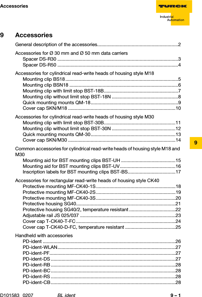
Contents
1.
annex to user manual
2.
User manual
annex to user manual
Navigation menu
Upload a User Manual
Namespaces
Wiki Guide
HTML
PDF
Info
Views
User Manual
Discussion / Help
Navigation

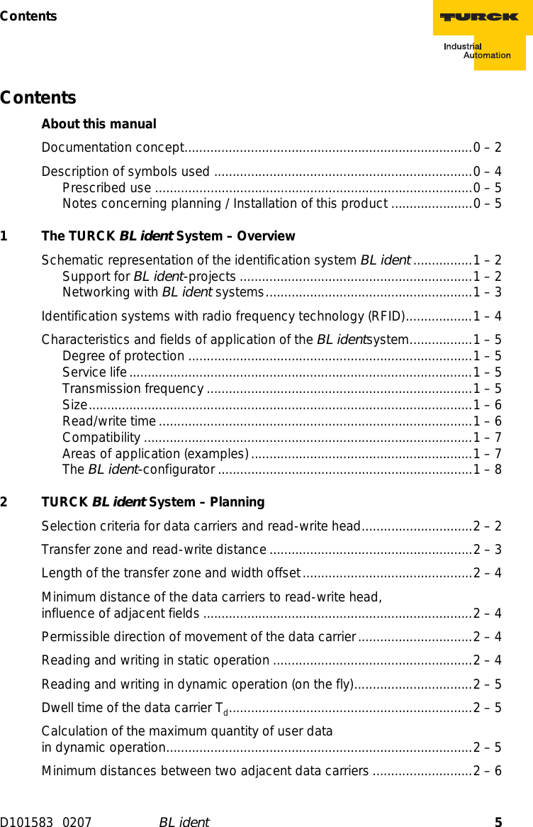

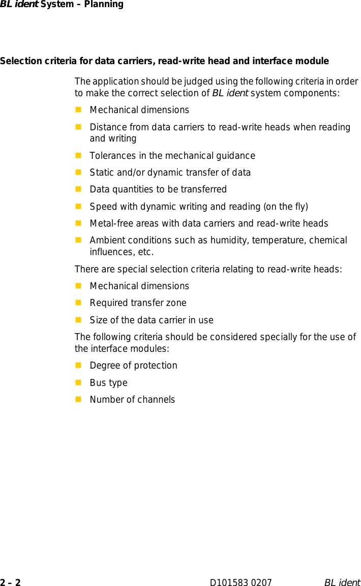
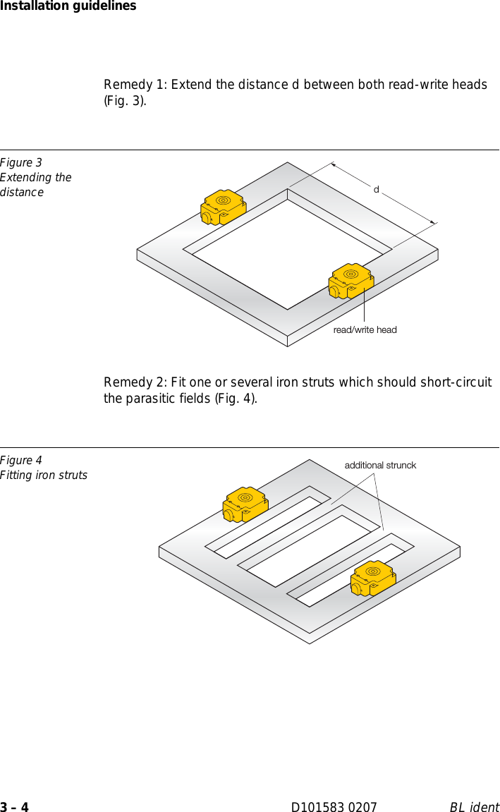
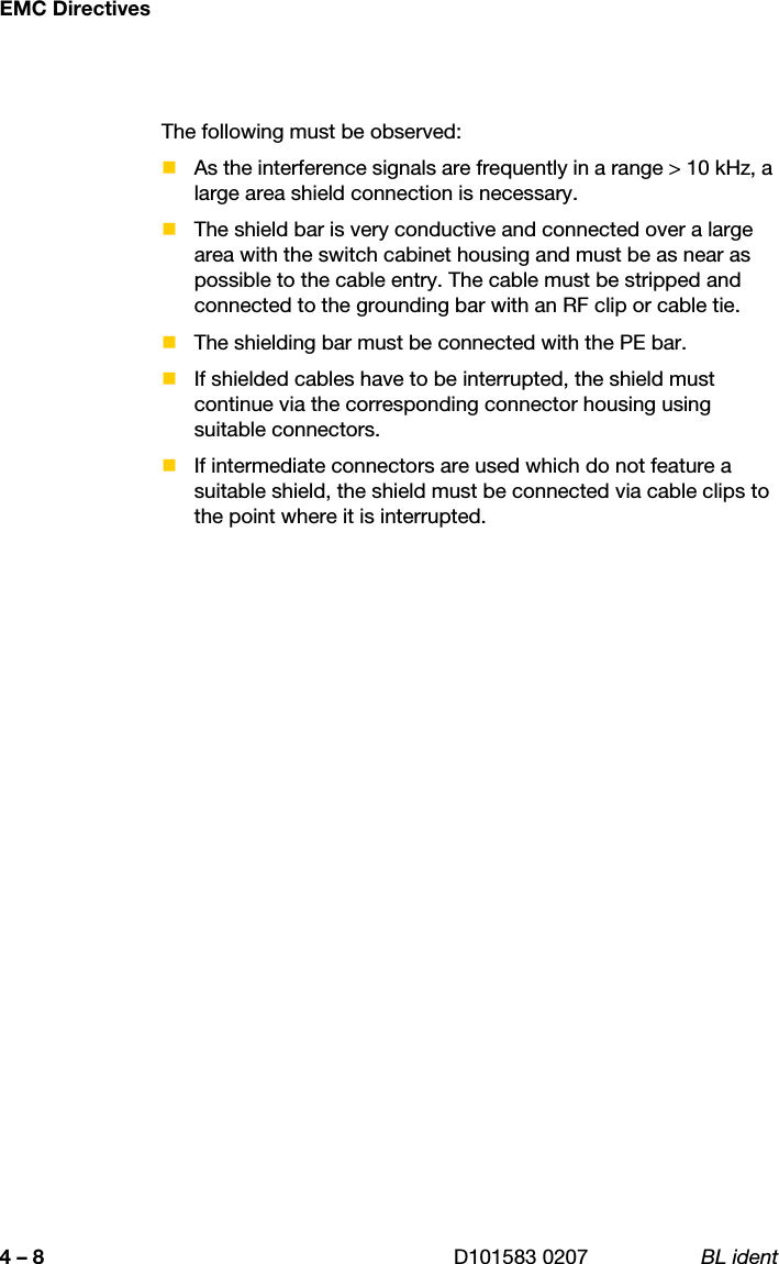


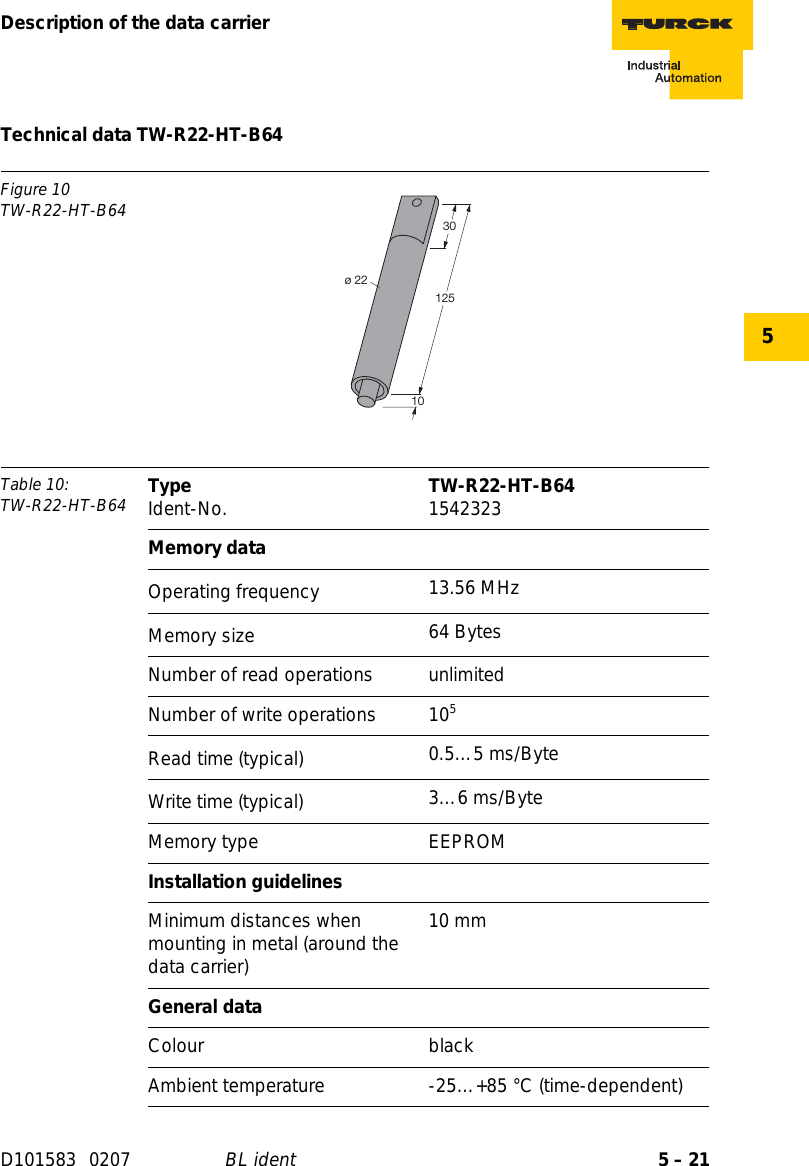
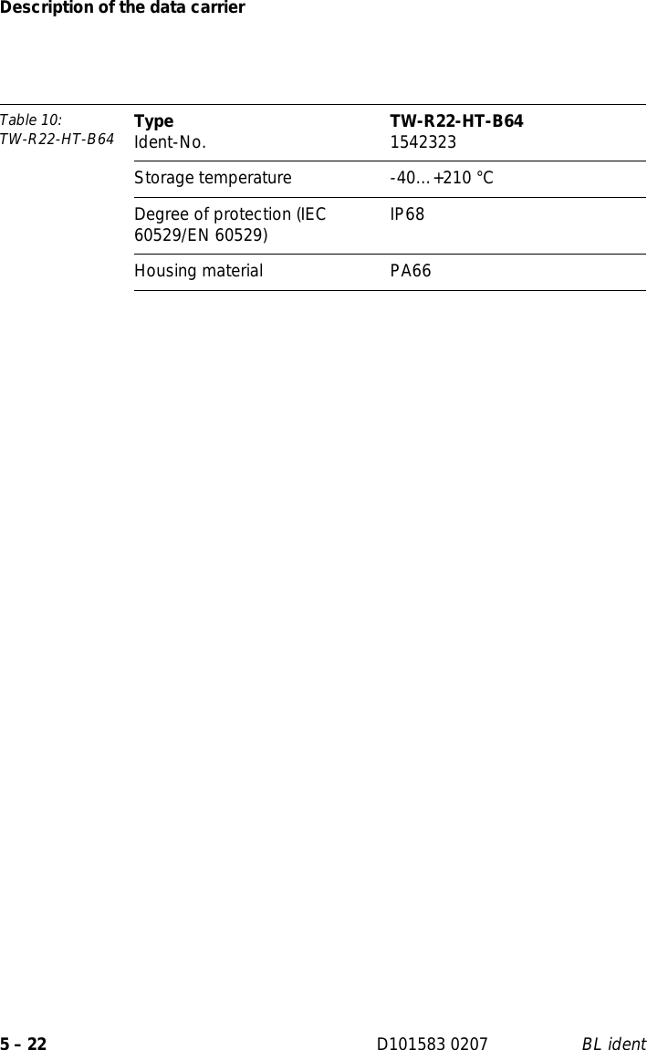


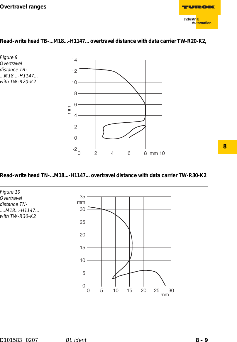
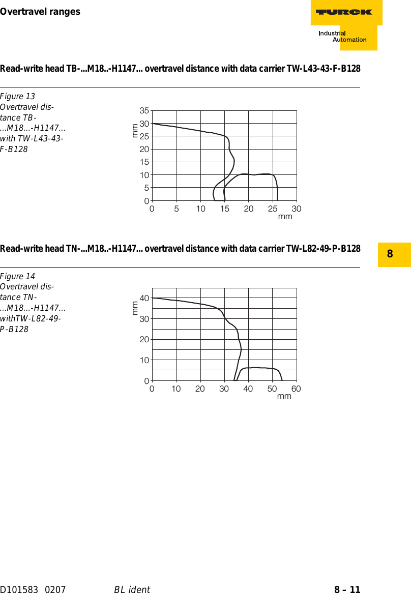
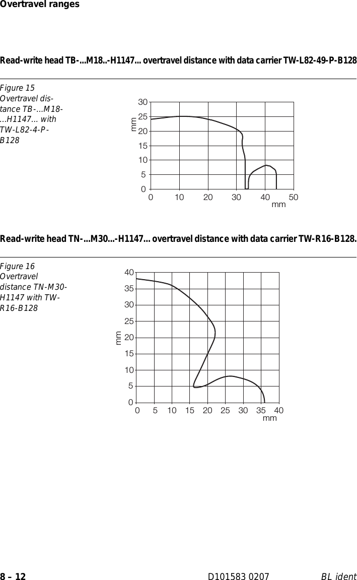
![7 – 3Operating dataD101583 0207 BL ident7Operating data for read-write head – TB-M18-H1147 – TB-EM18WD-H1147Table 1: Operating data TB-...M18...-H1147Corresponding data carrier Read-write distanceRecommended [mm] Maximum [mm]TW-R16-B128 613TW-R20-B128 613TW-R20-K2 512TW-I14-B128 613TW-L43-43-F-B128 15 30TW-L82-49-P-B128 15 23](https://usermanual.wiki/Hans-Turck-and-KG/TNQ120.annex-to-user-manual/User-Guide-3033182-Page-115.png)
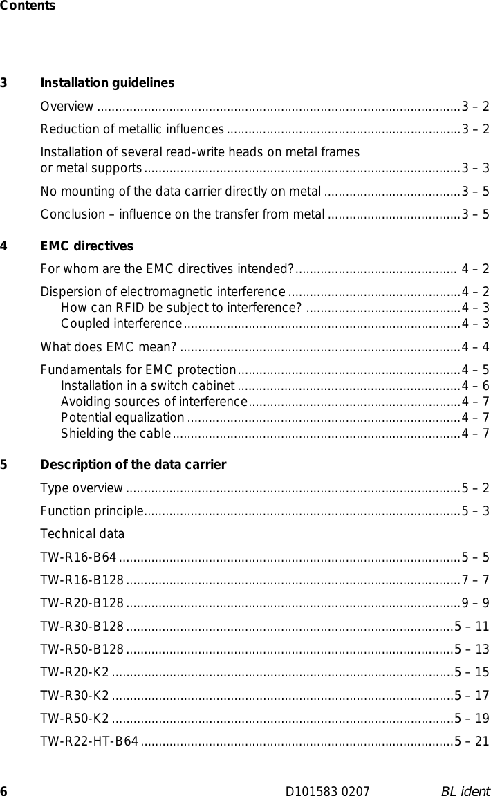
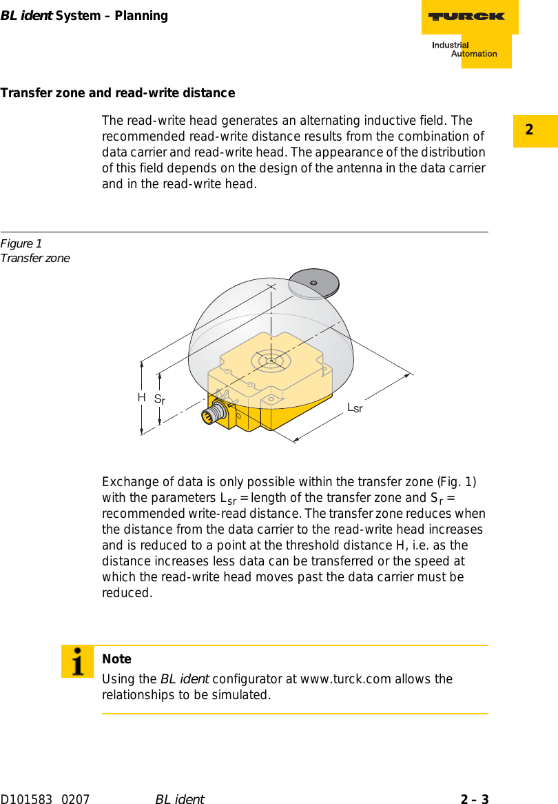
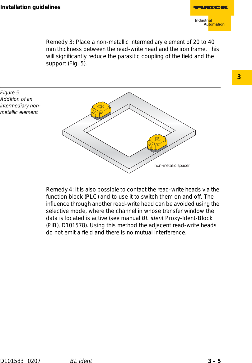
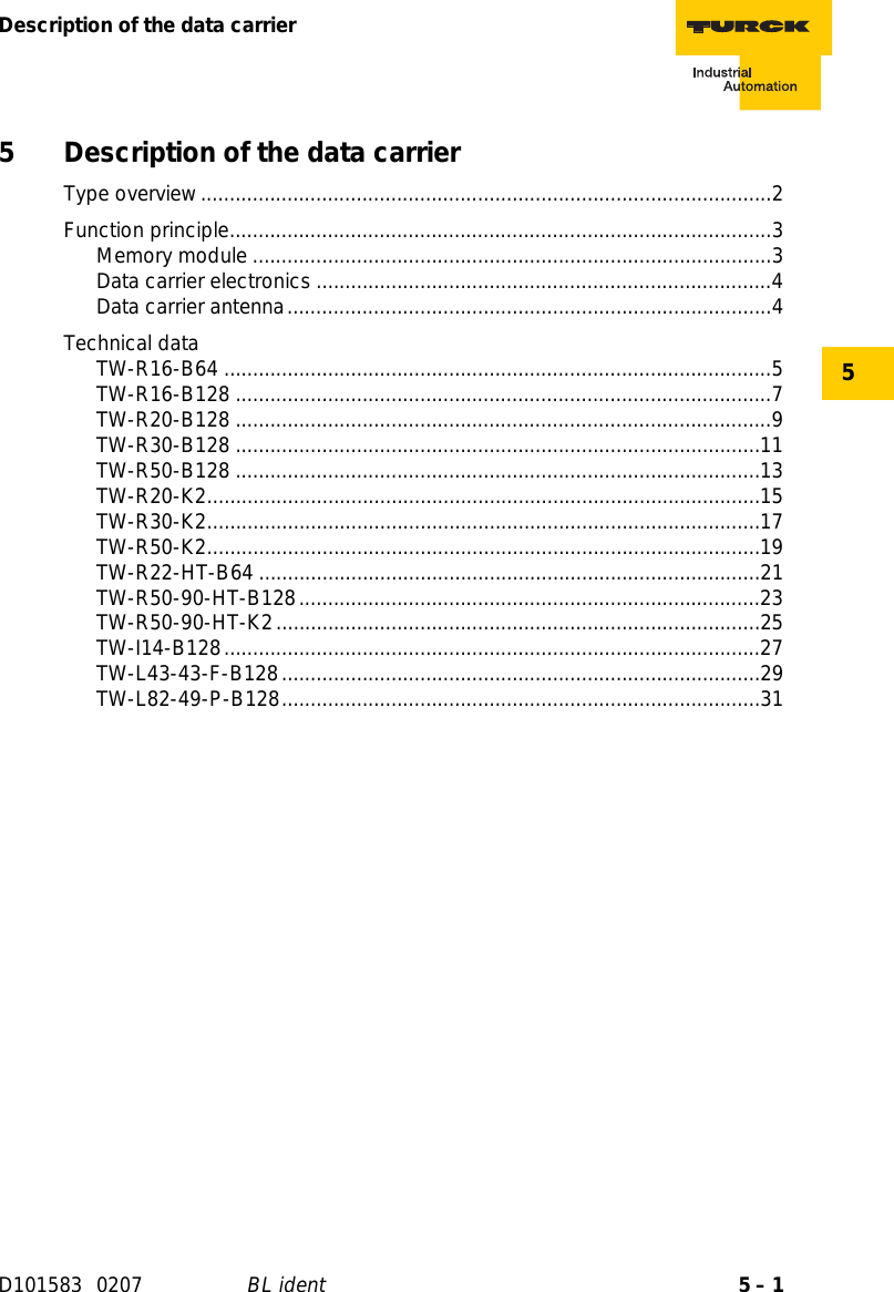
![Operating data7 – 4 D101583 0207 BL identOperating data for read-write head – TB-M18-H1147/S1126 – TB-EM18WD-H1147/S1126Table 2: Operating data TB-...M18...-H1147/S1126Corresponding data carrier Read-write distanceRecommended [mm] Maximum [mm]TW-R16-B64 613TW-R16-B128 613TW-R20-B128 613TW-I14-B128 613TW-L43-43-F-B128 15 30TW-L82-49-P-B128 15 23](https://usermanual.wiki/Hans-Turck-and-KG/TNQ120.annex-to-user-manual/User-Guide-3033182-Page-116.png)
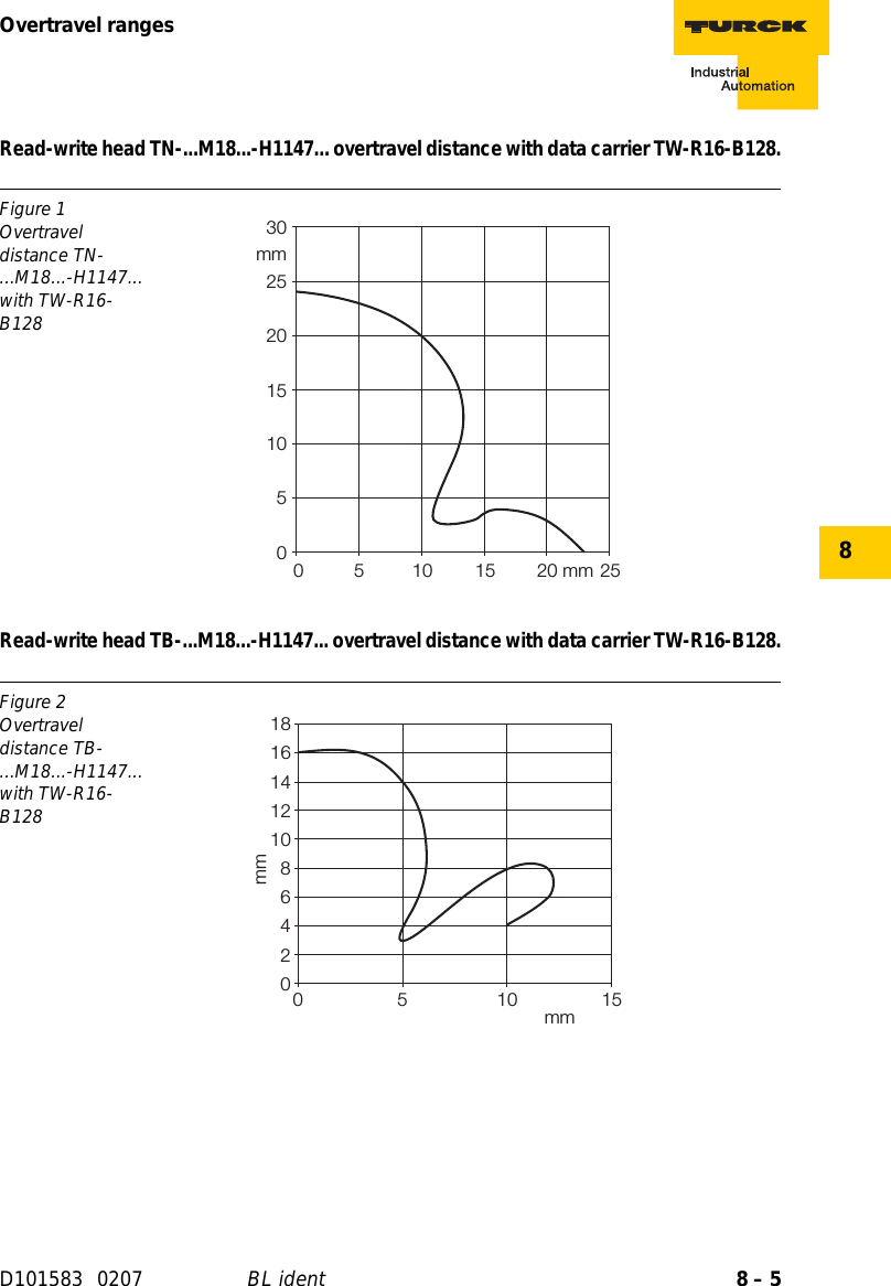
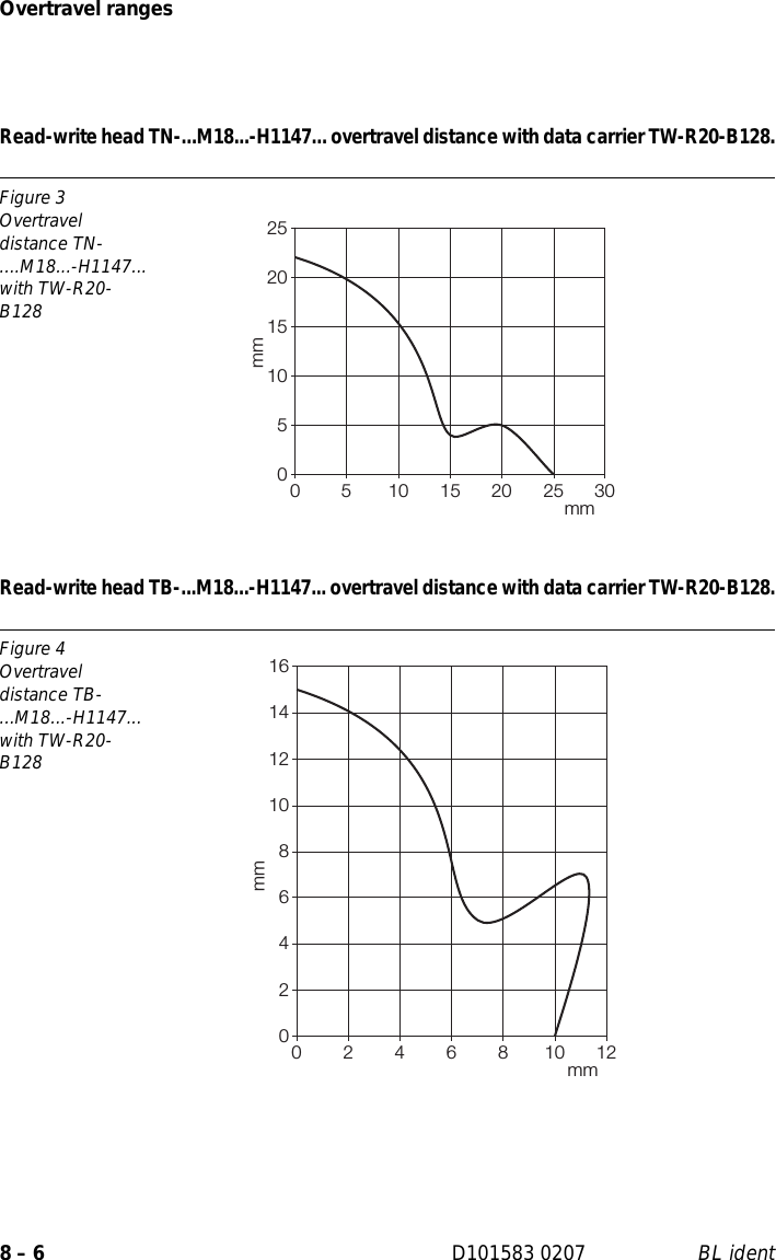
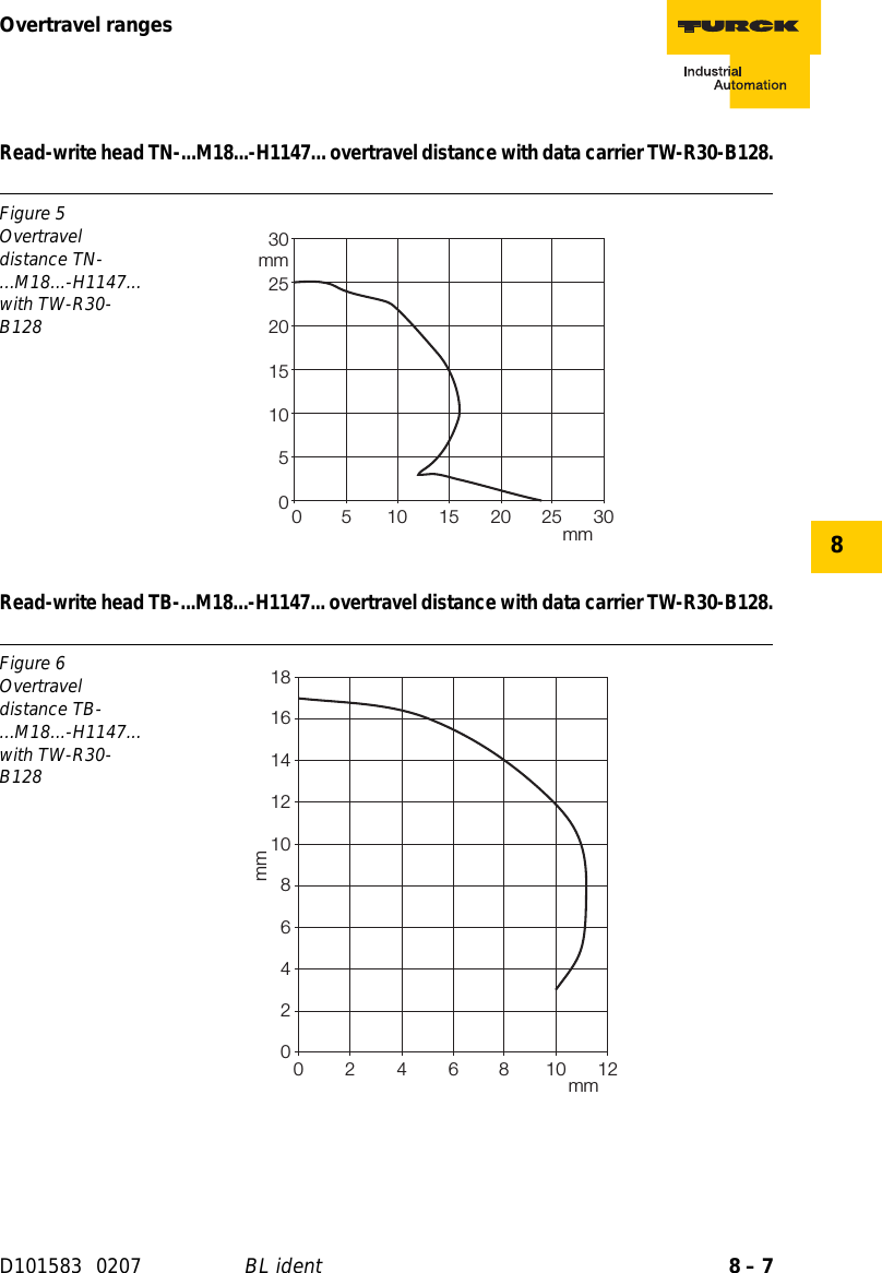
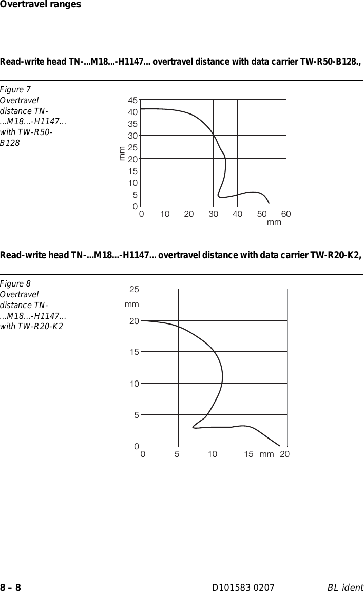
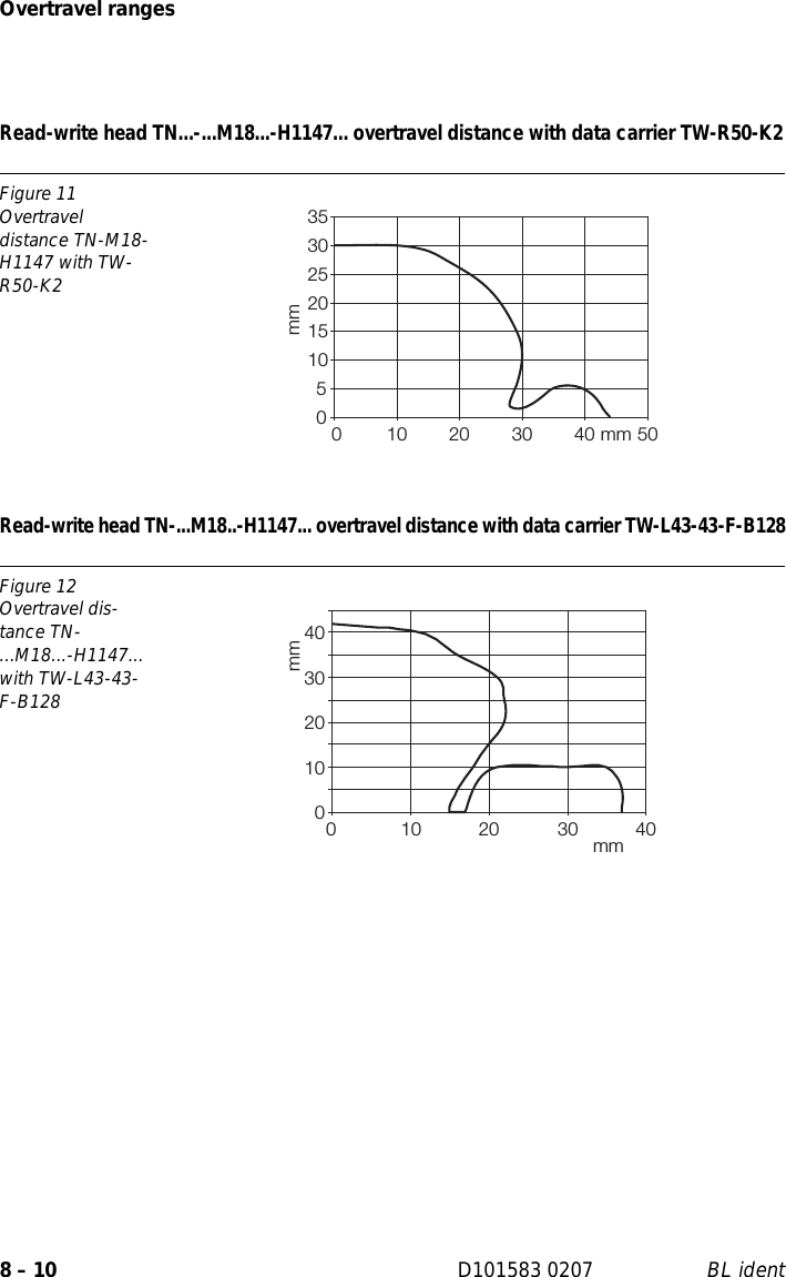
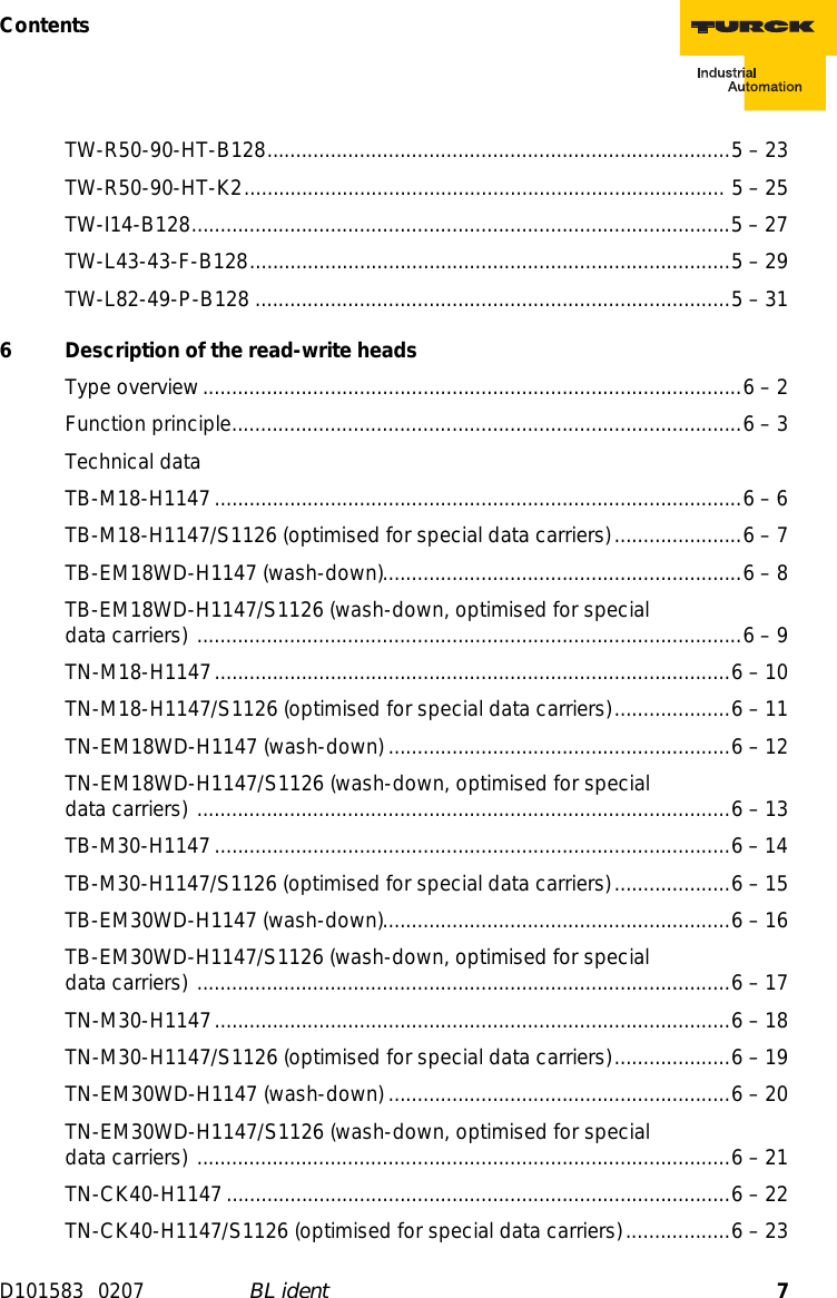
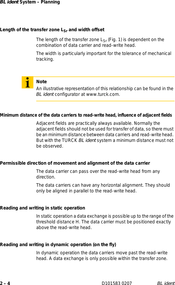
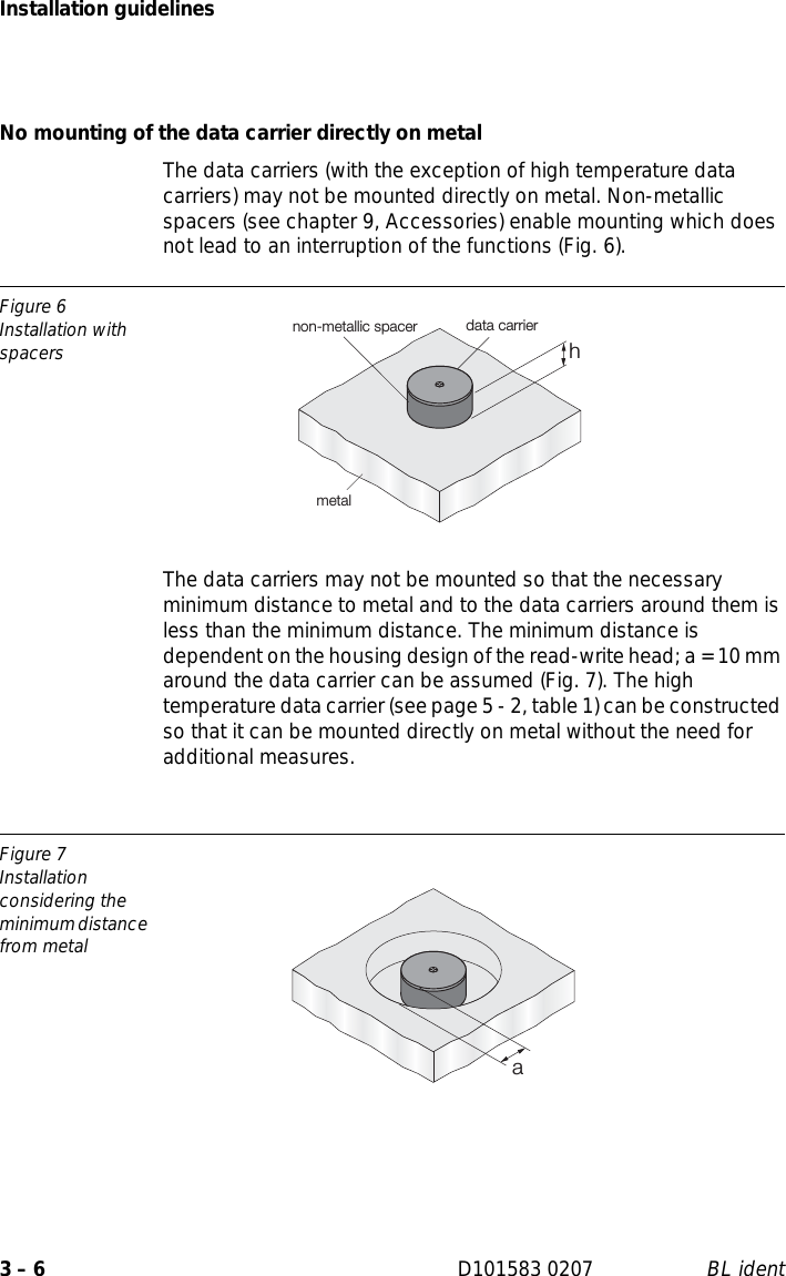
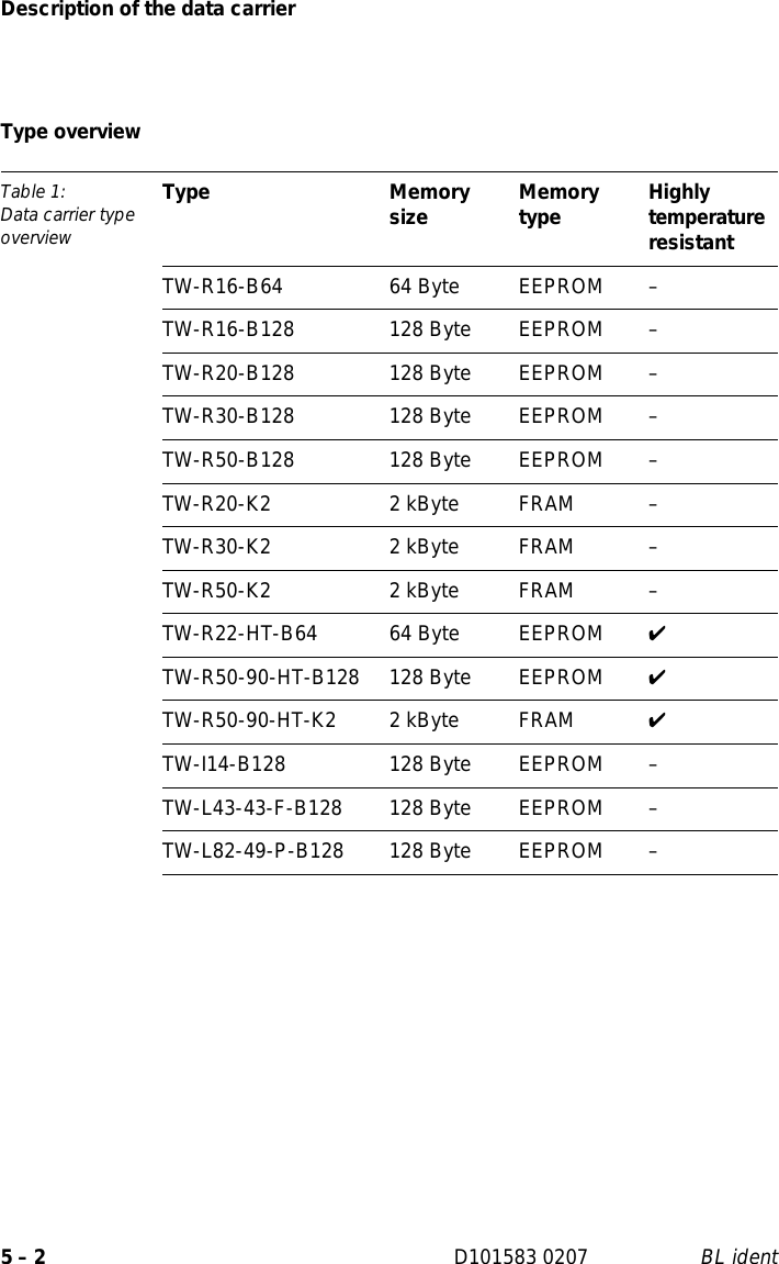
![7 – 5Operating dataD101583 0207 BL ident7Operating data for read-write head – TN-M18-H1147 – TN-EM18WD-H1147Table 3: Operating data TN-...M18...-H1147Corresponding data carrier Read-write distanceRecommended [mm] Maximum [mm]TW-R16-B128 12 23TW-R20-B128 10 22TW-R30-B128 10 25TW-R50-B128 20 41TW-R20-K2 12 20TW-R30-K2 16 31TW-R50-K2 12 30TW-I14-B128 10 22TW-L43-43-F-B128 25 45TW-L82-49-P-B128 20 40](https://usermanual.wiki/Hans-Turck-and-KG/TNQ120.annex-to-user-manual/User-Guide-3033182-Page-117.png)
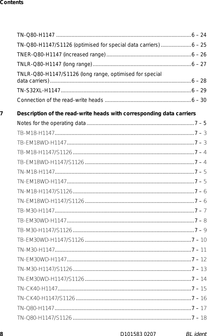
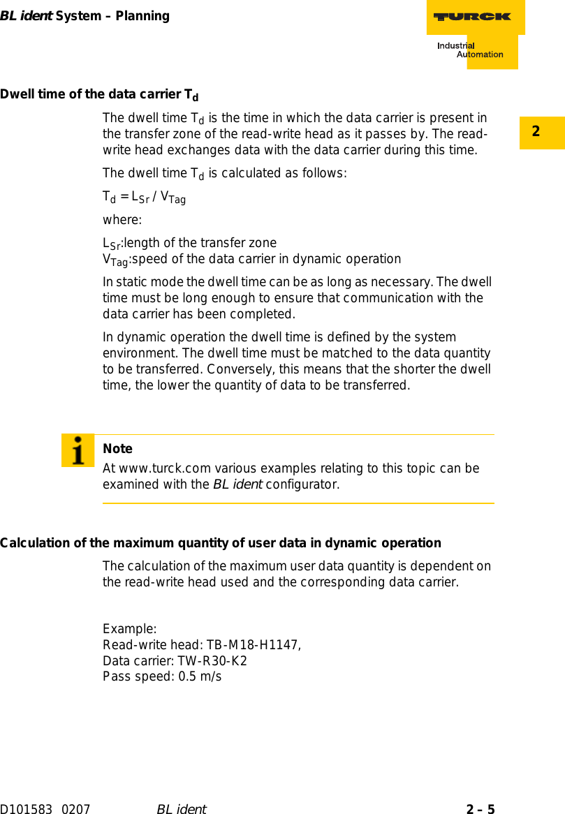
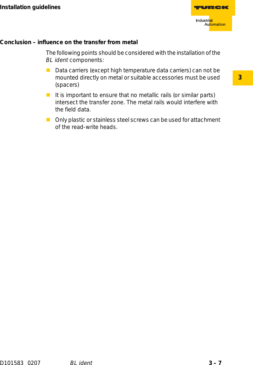
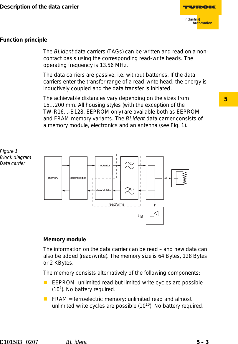
![Operating data7 – 6 D101583 0207 BL identOperating data for read-write head – TN-M18-H1147/S1126 – TN-EM18WD-H1147/S1126Table 4: Operating data TN-...M18...-H1147/S1126Corresponding data carrier Read-write distanceRecommended [mm] Maximum [mm]TW-R16-B64 613TW-R16-B128 613TW-R20-B128 613TW-R20-K2 512TW-I14-B128 613TW-L43-43-F-B128 15 30TW-L82-49-P-B128 15 23](https://usermanual.wiki/Hans-Turck-and-KG/TNQ120.annex-to-user-manual/User-Guide-3033182-Page-118.png)
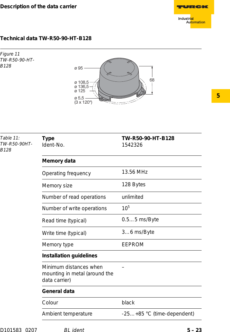
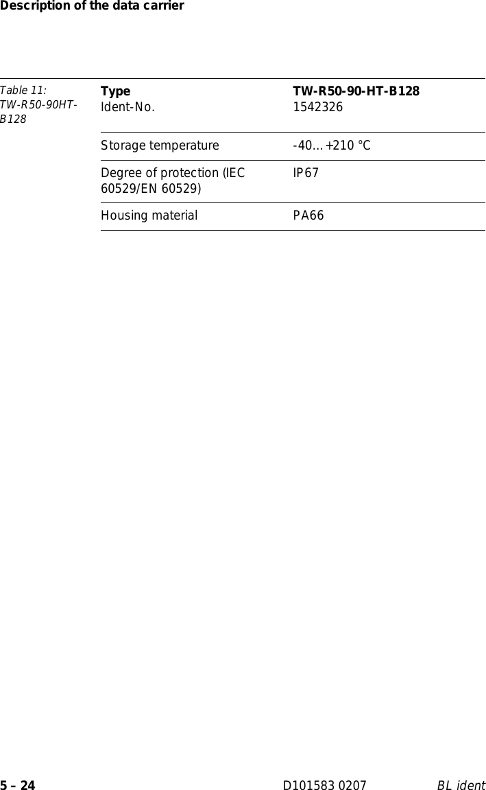
![7 – 7Operating dataD101583 0207 BL ident7Operating data for read-write head – TB-M30-H1147Table 5: Operating data TB-M30-H1147Corresponding data carrier Read-write distanceRecommended [mm] Maximum [mm]TW-R16-B64 12 23TW-R16-B128 12 23TW-R20-B128 15 27TW-R30-B128 13 30TW-R50-B128 20 43TW-R20-K2 15 22TW-R30-K2 15 27TW-R50-K2 15 33TW-R50-90-HT-B128 510TW-I14-B128 15 27TW-L43-43-F-B128 25 42TW-L82-49-P-B128 20 43](https://usermanual.wiki/Hans-Turck-and-KG/TNQ120.annex-to-user-manual/User-Guide-3033182-Page-119.png)
![Operating data7 – 8 D101583 0207 BL identOperating data for read-write head – TB-EM30WD-H1147Table 6: Operating data TB-...M30...-H1147Corresponding data carrier Read-write distanceRecommended [mm] Maximum [mm]TW-R16-B128 12 23TW-R20-B128 15 27TW-R30-B128 13 30TW-R50-B128 20 43TW-R20-K2 15 22TW-R30-K2 15 27TW-R50-K2 15 33TW-R50-90-HT-B128 510TW-I14-B128 15 27TW-L43-43-F-B128 25 42TW-L82-49-P-B128 20 43](https://usermanual.wiki/Hans-Turck-and-KG/TNQ120.annex-to-user-manual/User-Guide-3033182-Page-120.png)
![7 – 9Operating dataD101583 0207 BL ident7Operating data for read-write head – TB-M30-H1147/S1126Table 7: Operating data TB-M30-H1147/S1126Corresponding data carrier Read-write distanceRecommended [mm] Maximum [mm]TW-R16-B128 12 23TW-R20-B128 15 27TW-R30-B128 13 30TW-R50-B128 20 43TW-R22-HT-B64 517TW-R50-90-HT-B128 510TW-I14-B128 15 27TW-L43-43-F-B128 25 42TW-L82-49-P-B128 20 43](https://usermanual.wiki/Hans-Turck-and-KG/TNQ120.annex-to-user-manual/User-Guide-3033182-Page-121.png)
![Operating data7 – 10 D101583 0207 BL identOperating data for read-write head – TB-EM30WD-H1147/S1126Table 8: Operating data TB-...M30...-H1147/S1126Corresponding data carrier Read-write distanceRecommended [mm] Maximum [mm]TW-R16-B64 12 23TW-R16-B128 12 23TW-R20-B128 15 27TW-R30-B128 13 30TW-R50-B128 20 43TW-R22-HT-B64 517TW-R50-90-HT-B128 510TW-I14-B128 15 27TW-L43-43-F-B128 25 42TW-L82-49-P-B128 20 43](https://usermanual.wiki/Hans-Turck-and-KG/TNQ120.annex-to-user-manual/User-Guide-3033182-Page-122.png)
![7 – 11Operating dataD101583 0207 BL ident7Operating data for read-write head – TN-M30-H1147Table 9: Operating data TN-M30-H1147Corresponding data carrier Read-write distanceRecommen-ded [mm] Maximum [mm]TW-R16-B128 20 38TW-R20-B128 22 40TW-R30-B128 22 43TW-R50-B128 40 72TW-R20-K2 17 31TW-R30-K2 23 42TW-R50-K2 30 58TW-R50-90-HT-B128 19 39TW-R50-90-HT-K2 12 25TW-I14-B128 22 40TW-L43-43-F-B128 30 64TW-L82-49-P-B128 30 65](https://usermanual.wiki/Hans-Turck-and-KG/TNQ120.annex-to-user-manual/User-Guide-3033182-Page-123.png)
![Operating data7 – 12 D101583 0207 BL identOperating data for read-write head – TN-EM30WD-H1147Table 10: Operating data TN-...M30...-H1147Corresponding data carrier Read-write distanceRecommended [mm] Maximum [mm]TW-R16-B128 20 38TW-R20-B128 22 40TW-R30-B128 22 43TW-R50-B128 40 72TW-R20-K2 17 31TW-R30-K2 23 42TW-R50-K2 30 58TW-R50-90-HT-B128 19 39TW-R50-90-HT-K2 12 25TW-I14-B128 22 40TW-L43-43-F-B128 30 64TW-L82-49-P-B128 30 65](https://usermanual.wiki/Hans-Turck-and-KG/TNQ120.annex-to-user-manual/User-Guide-3033182-Page-124.png)
![7 – 13Operating dataD101583 0207 BL ident7Operating data for read-write head – TN-M30-H1147/S1126Table 11: Operating data TN-M30-H1147/S1126Corresponding data carrier Read-write distanceRecommended [mm] Maximum [mm]TW-R16-B64 20 38TW-R16-B128 20 38TW-R20-B128 22 40TW-R30-B128 22 43TW-R50-B128 40 72TW-R22-HT-B64 12 30TW-R50-90-HT-B128 19 39TW-I14-B128 22 40TW-L43-43-F-B128 30 64TW-L82-49-P-B128 30 65](https://usermanual.wiki/Hans-Turck-and-KG/TNQ120.annex-to-user-manual/User-Guide-3033182-Page-125.png)
![Operating data7 – 14 D101583 0207 BL identOperating data for read-write head – TN-EM30WD-H1147/S1126Table 12: Operating data TN-EM30WD-H1147/S1126Corresponding data carrier Read-write distanceRecommended [mm] Maximum [mm]TW-R16-B64 20 38TW-R16-B128 20 38TW-R20-B128 22 40TW-R30-B128 22 43TW-R50-B128 40 72TW-R22-HT-B64 12 30TW-R50-90-HT-B128 19 39TW-I14-B128 22 40TW-L43-43-F-B128 30 64TW-L82-49-P-B128 30 65](https://usermanual.wiki/Hans-Turck-and-KG/TNQ120.annex-to-user-manual/User-Guide-3033182-Page-126.png)
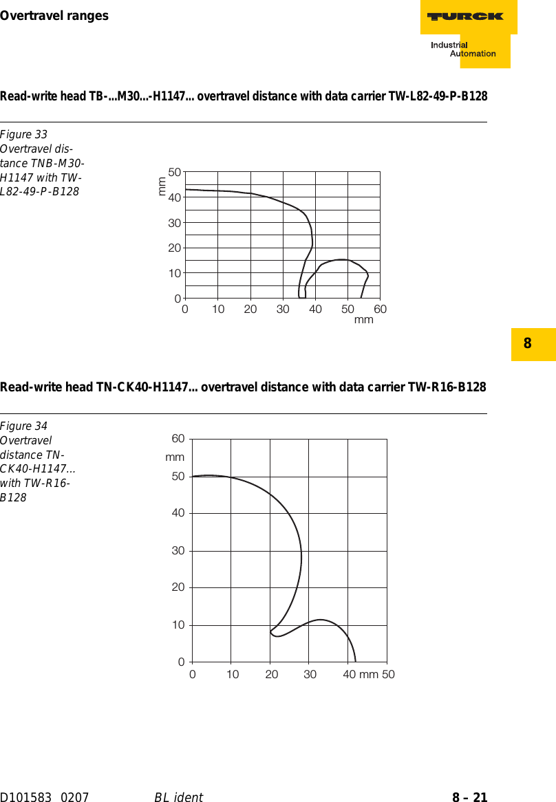
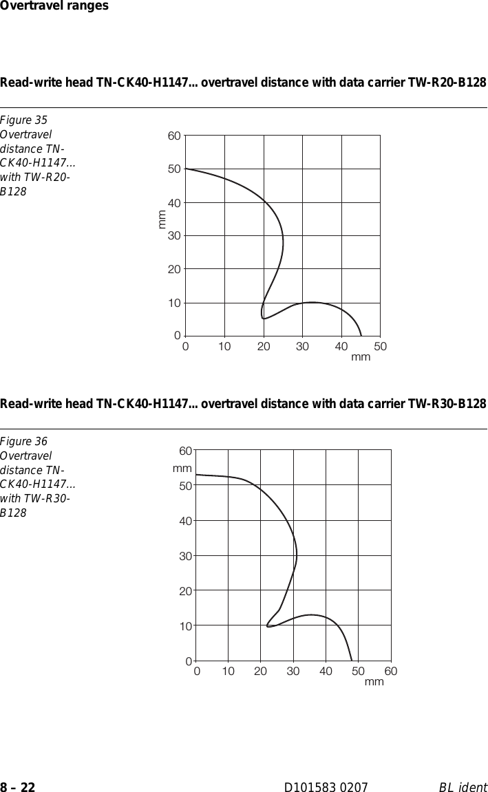
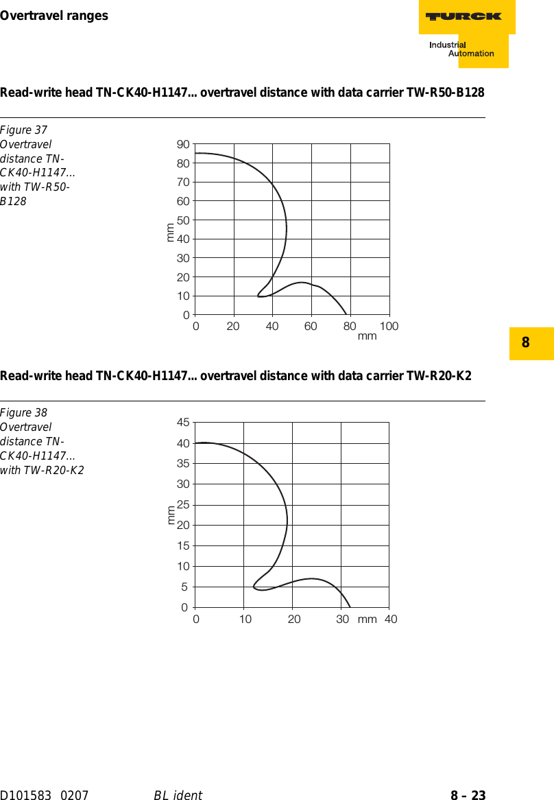
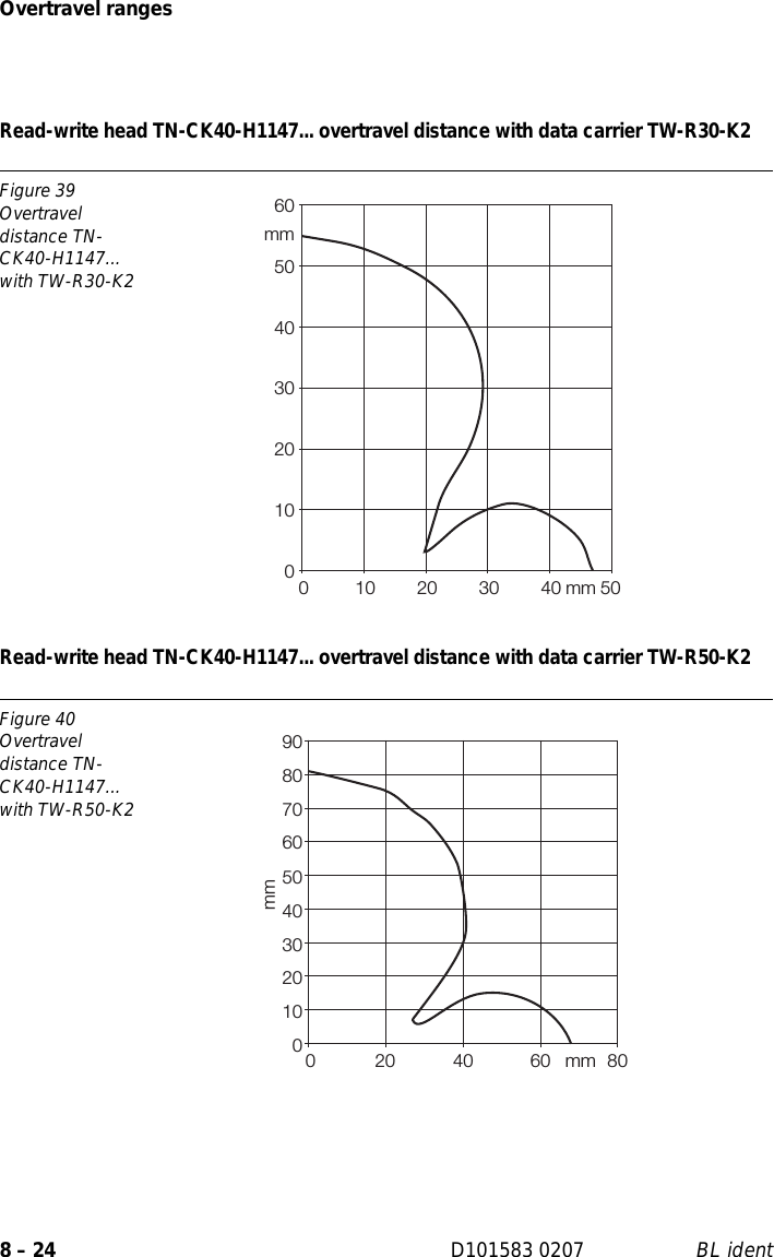
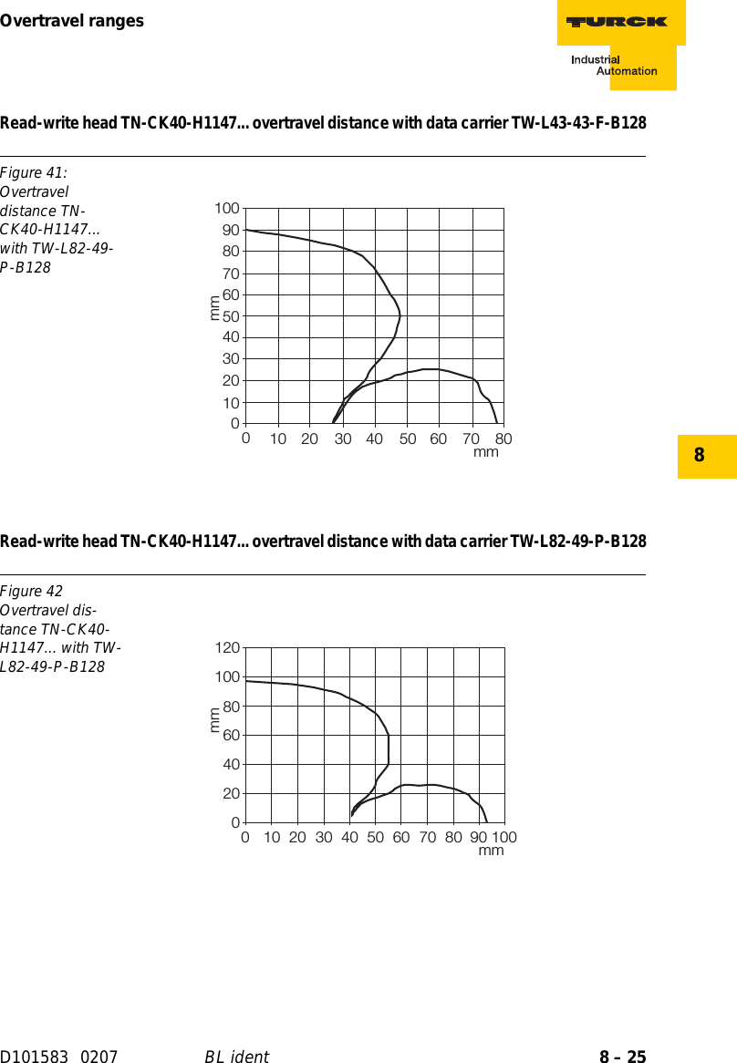
![7 – 15Operating dataD101583 0207 BL ident7Operating data for read-write head – TN-CK40-H1147Table 13: Operating data TN-CK40-H1147Corresponding data carrier Read-write distanceRecommended [mm] Maximum [mm]TW-R16-B64 28 50TW-R16-B128 28 50TW-R20-B128 30 50TW-R30-B128 30 53TW-R50-B128 45 85TW-R20-K2 22 40TW-R30-K2 30 55TW-R50-K2 38 81TW-R50-90-HT-B128 26 52TW-R50-90-HT-K2 24 48TW-I14-B128 30 50TW-L43-43-F-B128 50 90TW-L82-49-P-B128 50 96](https://usermanual.wiki/Hans-Turck-and-KG/TNQ120.annex-to-user-manual/User-Guide-3033182-Page-127.png)
![Operating data7 – 16 D101583 0207 BL identOperating data for read-write head – TN-CK40-H1147/S1126Table 14: Operating data TN-CK40-H1147/S1126Corresponding data carrier Read-write distanceRecommended [mm] Maximum [mm]TW-R16-B64 28 50TW-R16-B128 28 50TW-R20-B128 30 50TW-R30-B128 30 53TW-R50-B128 45 85TW-R22-HT-B64 20 40TW-R50-90-HT-B128 26 52TW-I14-B128 30 50TW-L43-43-F-B128 50 90TW-L82-49-P-B128 50 96](https://usermanual.wiki/Hans-Turck-and-KG/TNQ120.annex-to-user-manual/User-Guide-3033182-Page-128.png)
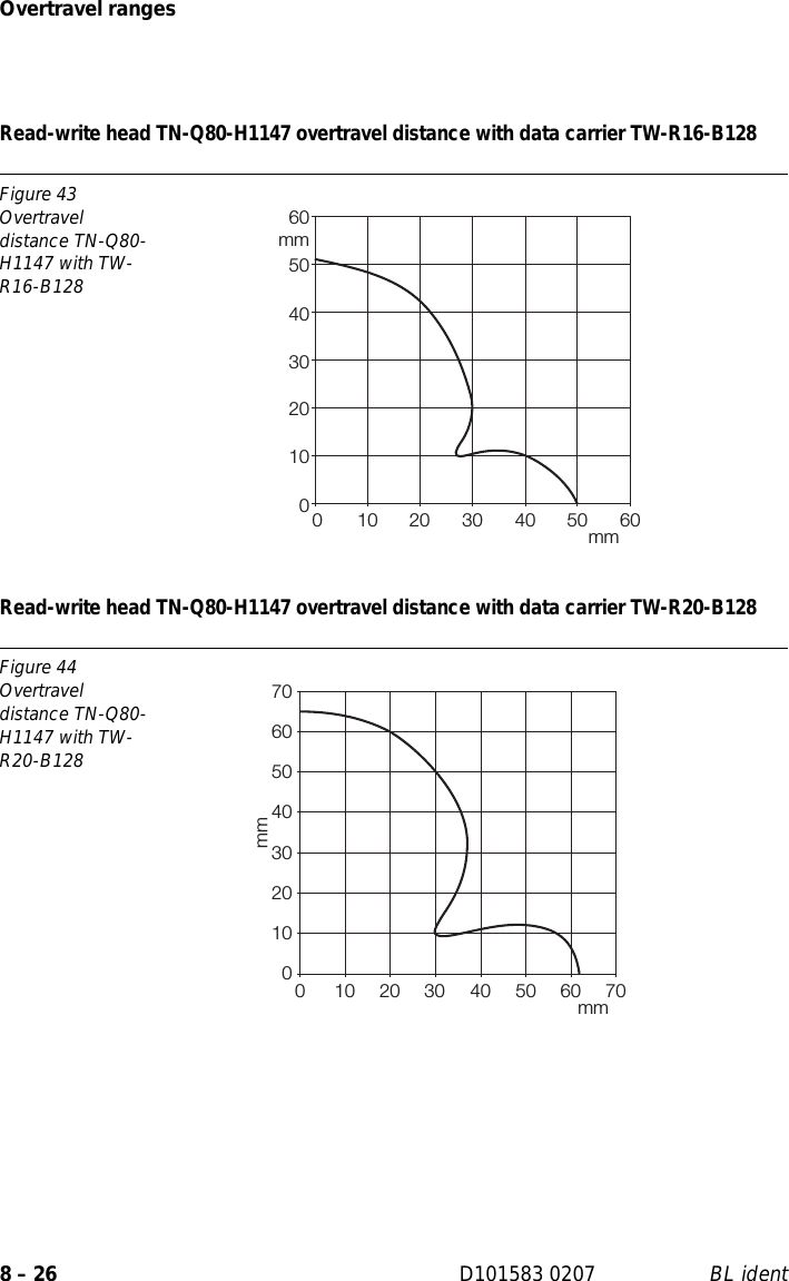
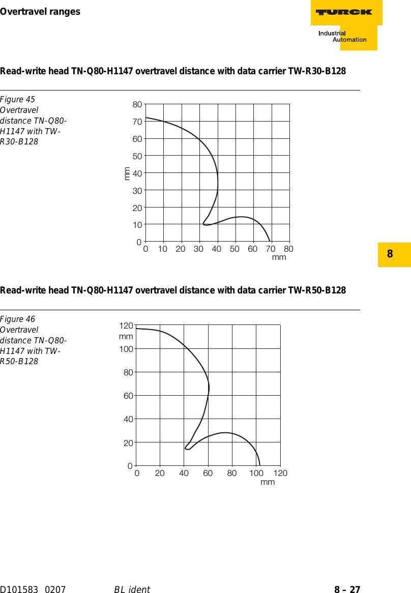
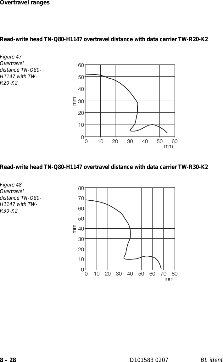
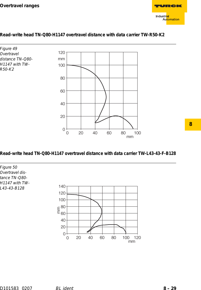
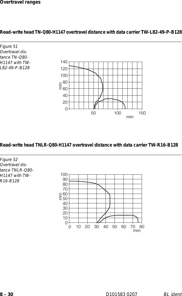
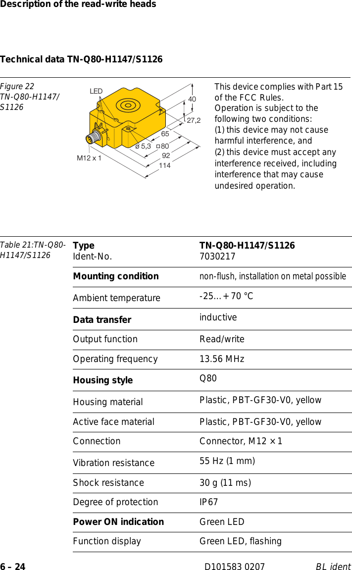
![7 – 17Operating dataD101583 0207 BL ident7Operating data for read-write head – TN-Q80-H1147Table 15: Operating data TN-Q80-H1147Corresponding data carrier Read-write distanceRecommen-ded [mm] Maximum [mm]TW-R16-B128 20 52TW-R20-B128 35 65TW-R30-B128 35 72TW-R50-B128 65 118TW-R20-K2 25 52TW-R30-K2 35 67TW-R50-K2 50 100TW-R50-90-HT-B128 42 85TW-R50-90-HT-K2 33 67TW-I14-B128 35 65TW-L43-43-F-B128 60 115TW-L82-49-P-B128 65 128](https://usermanual.wiki/Hans-Turck-and-KG/TNQ120.annex-to-user-manual/User-Guide-3033182-Page-129.png)
![Operating data7 – 18 D101583 0207 BL identOperating data for read-write head – TN-Q80-H1147/S1126Table 16: Operating data TN-Q80-H1147/S1126Corresponding data carrier Read-write distanceRecommended [mm] Maximum [mm]TW-R16-B64 20 52TW-R16-B128 20 52TW-R20-B128 35 65TW-R30-B128 35 72TW-R50-B128 65 118TW-R20-K2 25 52TW-R22-HT-B64 25 55TW-R50-90-HT-B128 42 85TW-I14-B128 35 65TW-L43-43-F-B128 60 115TW-L82-49-P-B128 65 128](https://usermanual.wiki/Hans-Turck-and-KG/TNQ120.annex-to-user-manual/User-Guide-3033182-Page-130.png)
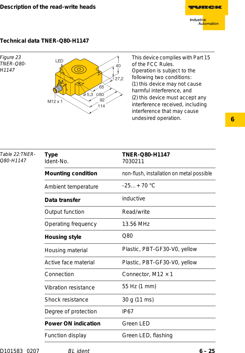
![7 – 19Operating dataD101583 0207 BL ident7Operating data for read-write head – TNER-Q80-H1147Table 17: Operating data TNER-Q80-H1147Corresponding data carrier Read-write distanceRecommended [mm] Maximum [mm]TW-R16-B64 20 52TW-R22-HT-B64 35 70](https://usermanual.wiki/Hans-Turck-and-KG/TNQ120.annex-to-user-manual/User-Guide-3033182-Page-131.png)
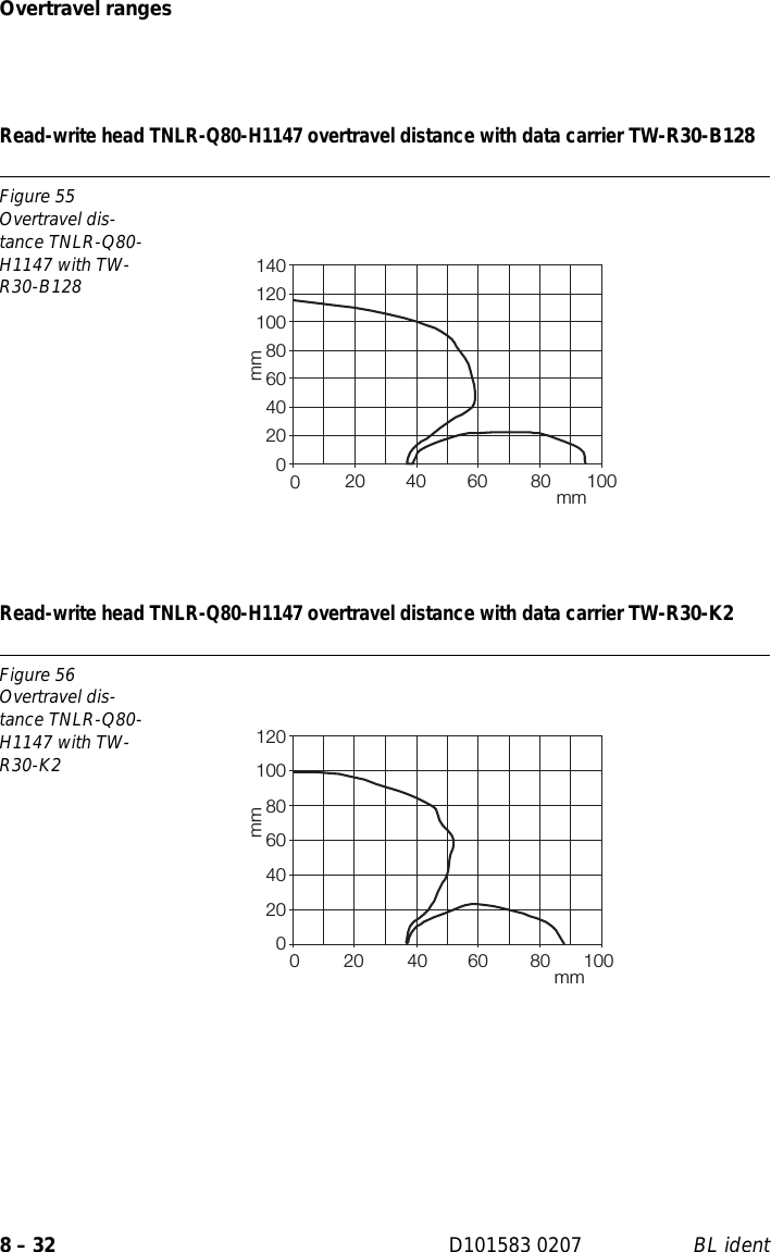
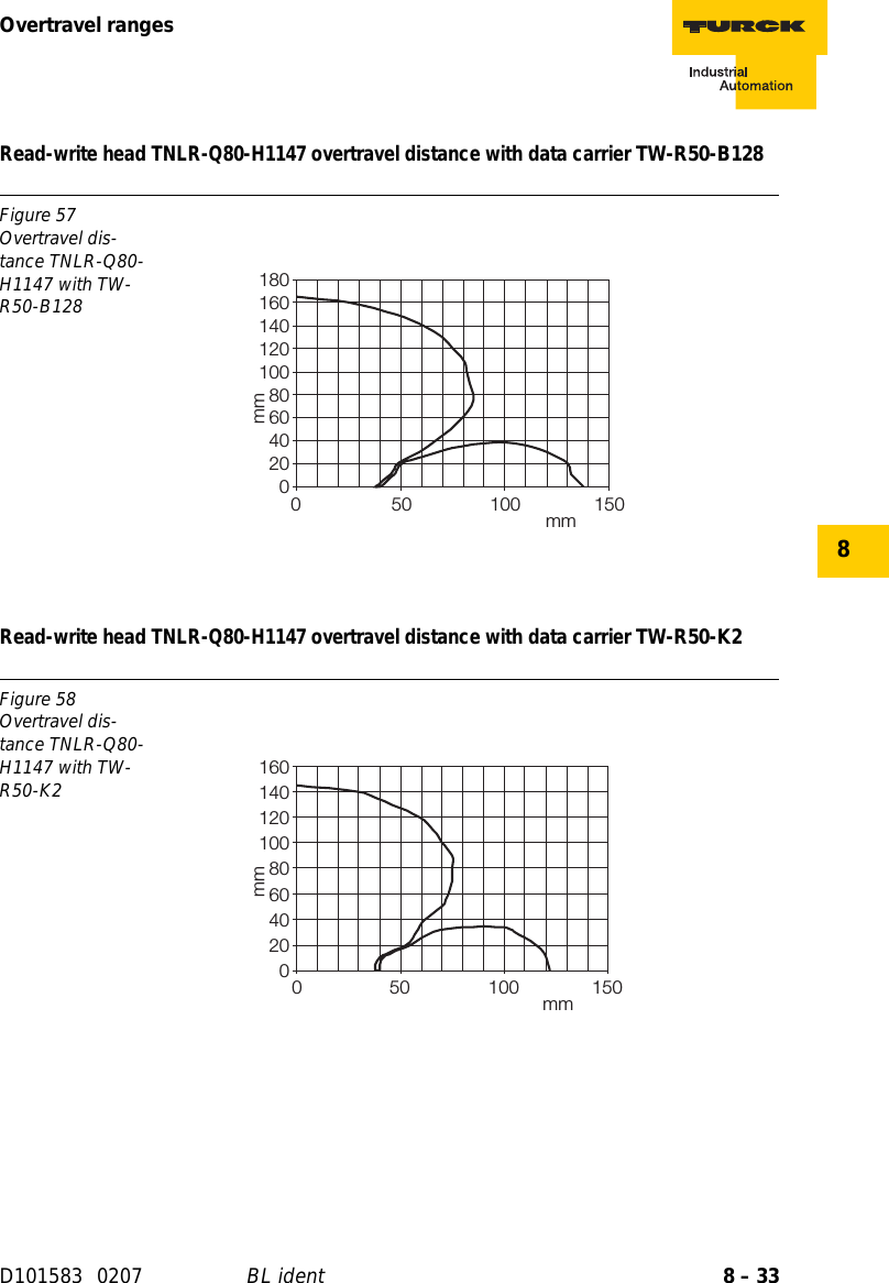
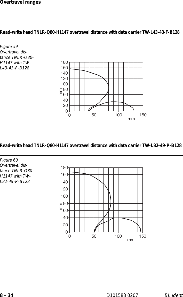
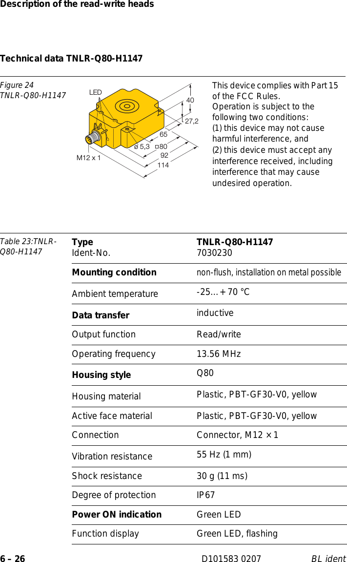
![Operating data7 – 20 D101583 0207 BL identOperating data for read-write head – TNLR-Q80-H1147Table 18: Operating data TNLR-Q80-H1147Corresponding data carrier Read-write distanceRecommended [mm] Maximum [mm]TW-R16-B128 50 85TW-R20-B128 50 88TW-R30-B128 60 115TW-R50-B128 80 165TW-R20-K2 40 75TW-R30-K2 60 98TW-R50-K2 90 144TW-R50-90-HT-B128 60 135TW-R50-90-HT-K2 60 114TW-I14-B128 50 85TW-L43-43-F-B128 90 155TW-L82-49-P-B128 90 168](https://usermanual.wiki/Hans-Turck-and-KG/TNQ120.annex-to-user-manual/User-Guide-3033182-Page-132.png)
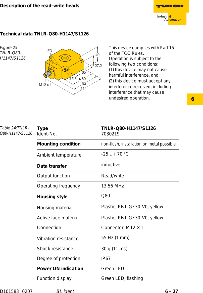
![7 – 21Operating dataD101583 0207 BL ident7Operating data for read-write head – TNLR-Q80-H1147/S1126Table 19: Operating data TNLR-Q80-H1147/S1126Corresponding data carrier Read-write distanceRecommended [mm] Maximum [mm]TW-R20-B128 50 88TW-R30-B128 60 115TW-R50-B128 80 165TW-R22-HT-B64 39 74TW-R50-90-HT-B128 60 135TW-I14-B128 50 85TW-L43-43-F-B128 90 155TW-L82-49-P-B128 90 168](https://usermanual.wiki/Hans-Turck-and-KG/TNQ120.annex-to-user-manual/User-Guide-3033182-Page-133.png)
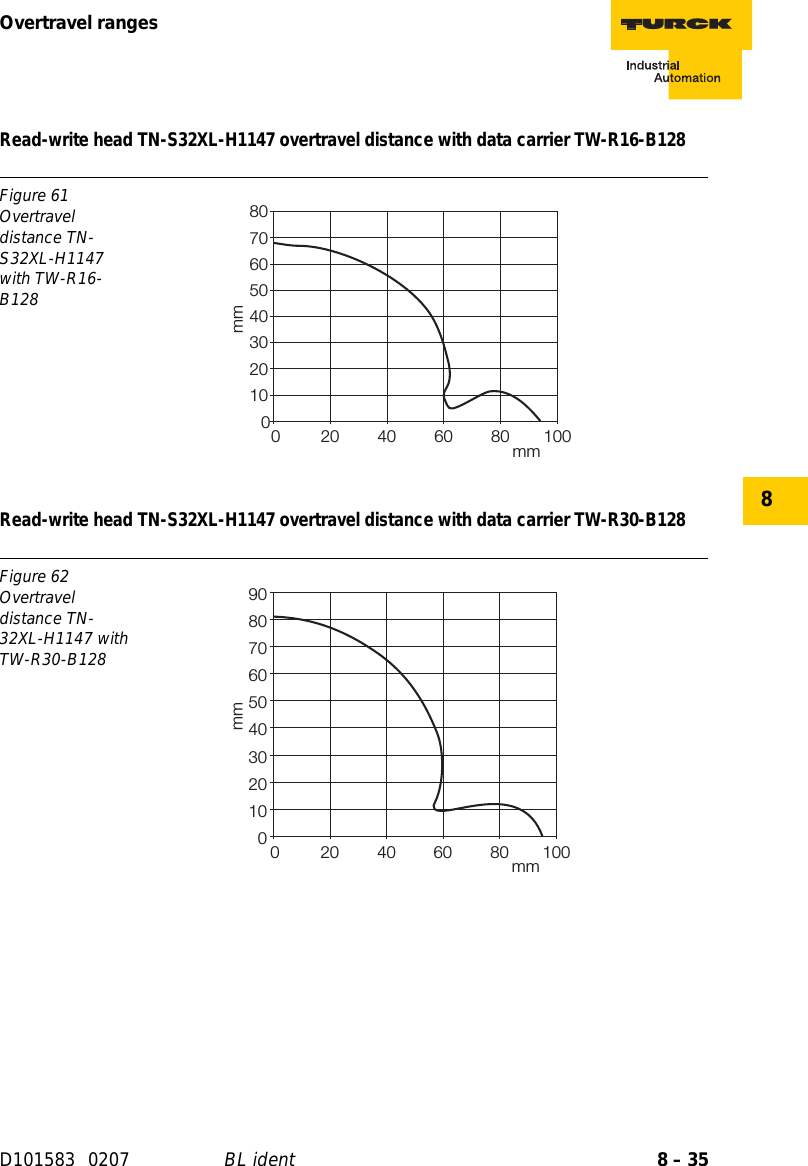
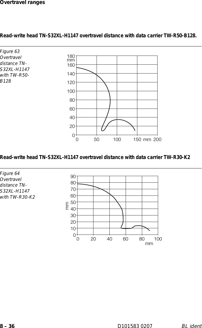
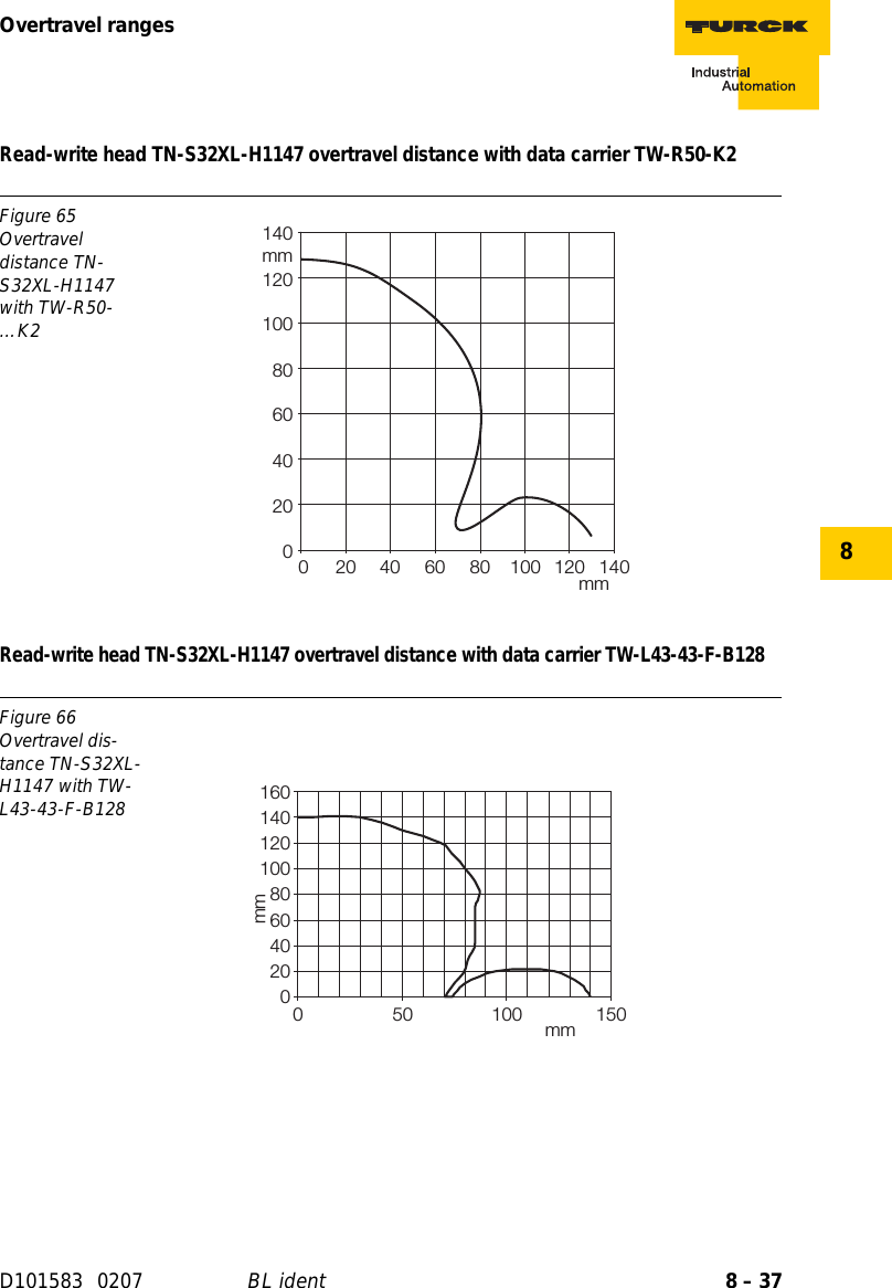
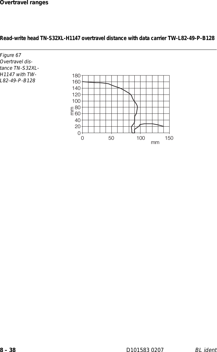
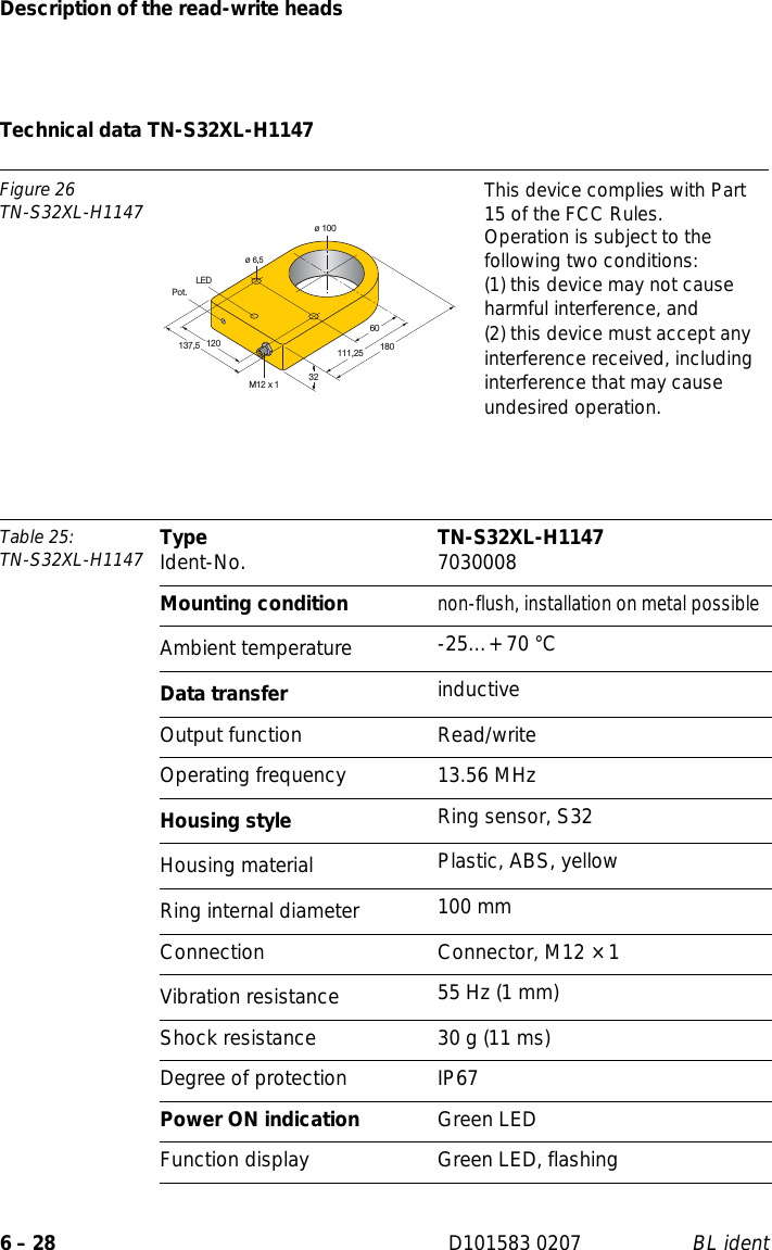
![Operating data7 – 22 D101583 0207 BL identOperating data for read-write head – TN-S32XL-H1147Table 20: Operating data TN-S32XL-H1147Corresponding data carrier Read-write distanceRecommen-ded [mm] Maximum [mm]TW-R16-B128 20 67TW-R20-B128 36 72TW-R30-B128 30 80TW-R50-B128 80 150TW-R20-K2 32 64TW-R30-K2 30 78TW-R50-K2 60 128TW-R50-90-HT-B128 58 1117TW-R50-90-HT-K2 42 85TW-I14-B128 36 72TW-L43-43-F-B128 80 140TW-L82-49-P-B128 80 160](https://usermanual.wiki/Hans-Turck-and-KG/TNQ120.annex-to-user-manual/User-Guide-3033182-Page-134.png)