Hansong MSE3CHA SB335, PS-35 (Mini Amplifier) User Manual INS SB335 Outlined
Hansong(Nanjing) Technology Ltd. SB335, PS-35 (Mini Amplifier) INS SB335 Outlined
UserManual.wiki
>
Hansong
>
MSE3CHA User Manual
User Manual V3.0
Navigation menu
Upload a User Manual
Namespaces
Wiki Guide
HTML
PDF
Info
Views
User Manual
Discussion / Help
Navigation
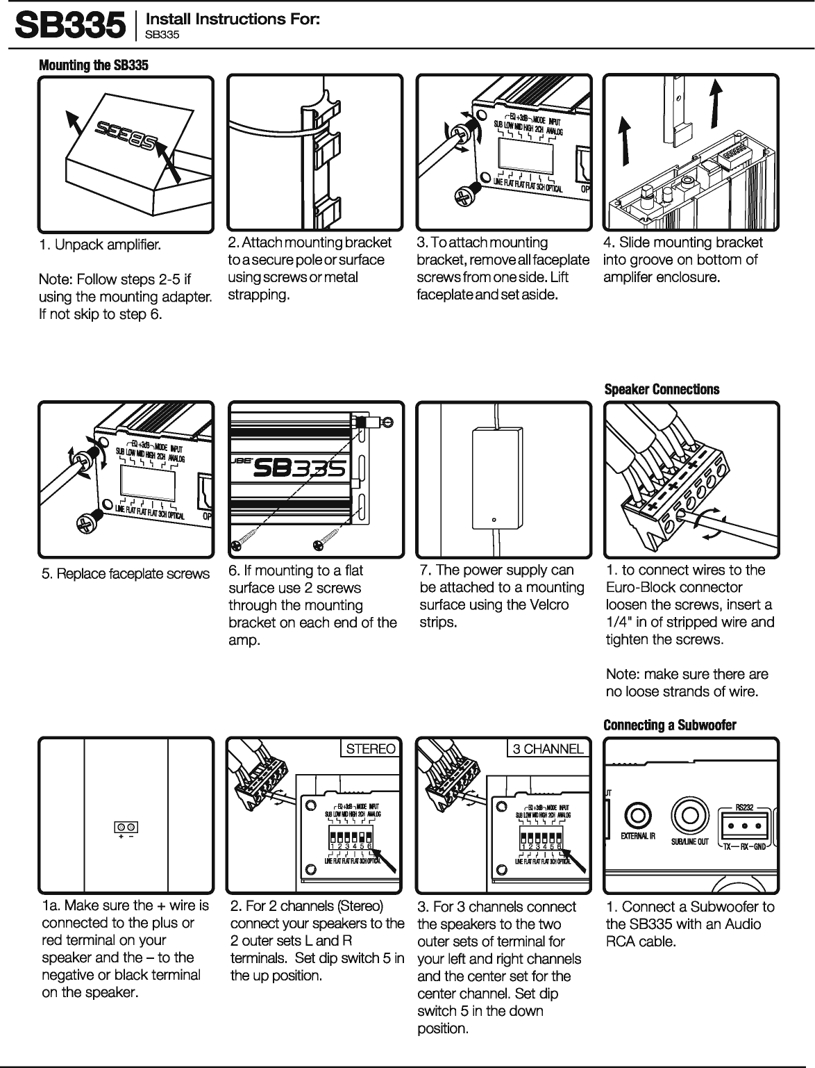
![SCUNOTUee· L.ead. or follow. 88335 I ~~:!:II Instructions For: The 88335 is a 2 or 3 channel amplifier with Dolby Digital decoding. It is designed to be used with either an analog or digital input from a 1V or other audio source. With a digital input it automatically senses Dolby Digital and PCM and switches modes. The 88335 takes the input signal from an audio source, decodes it and outputs either a 2 or 3 channel amplified signal to a sound bar or set of speakers. When set in the 2 channel mode it will take a stereo or multi-channel signal and mix it down to 2 output channels (left and right). When set in the 3 channel mode it will take a stereo or multi-channel signal and mix it into 3 output channels (left, right and center). In either mode there is a sub out option. When used in place of internal 1V speakers, change the 1V's audio setting to external speakers. Teach the 88335 the 1V's volume codes and it seamlessly operates with no additional remotes. Box Contents 1-Amplifier 1-Bluetooth® antenna 1-IR receiverwith 1m cord 1-32V, 3.75Apowersupply 1-Six-pin Euroblockconnectors 1-Three-pin Euroblockconnectors 1-Mounting bracket 2-2"Velcrostrips 1-Double sided tape disk for IR receiver 0 rfll+Mhlllll ~PIIT IINPliTSI SIBLIIIIMIDIIII2Ilii/III.IIG .., .., ~ ~ r' r' IBBBBBBI [J] © ANALOG ,.J ~ I I \ L, OPTICAL Llf RAI RAT RAT 3QIOPII'II. 0 Front Warning ON/Off 0 0 32'/0C @ POWER INPUT ~~R ~ ~-:-~~::.~ 0 STATIJS ~ [I) DOLBY. DIGITAL 0 0 0 Rear 1.435.647.9555 I 800.647.TUBE I www.soundtube.com ©2015 SoundTube Entertainment, Inc. All rights reserved. PN INS.SB335 Rev03.17.2015 SoundTube products must be installed by a professional audio installer/contractor. For safety and for optimum audio performance, installer must follow all directions issued by SoundTube Entertainment.](https://usermanual.wiki/Hansong/MSE3CHA/User-Guide-2666908-Page-1.png)
![883351 ~~~!:II Instructions For: RS232 Control 1 . Connect the RS232 control device to the RS232 port on the SB335. Refer to Step 1 of "Speaker Connections" for instructions on wiring the Euro-Biock connector. Pairing with a Bluetooth device ON/OFF ~ VOWME y 2/@ [I]~gtRv.o 1. Turn the SB335 on by pressing the on/off button. The LED will turn white when on. Equalizer settings _L I Q.....,-Blt311hMOOE INPUT &IB IJIN PliO HEH 201 NW.OG .., .., , ~ r' r' ~~~~~~~I ,..J ,-I ~ I \ L, Ill RAT RAT RAT 3Qlll'ltll. 0 1 . There are two EQ settings you can choose flat or +3d B. Baud Rate 115200 Data Bits8 Parity none Stop bit 1 Flow Control none 2. All serial commands should be sent as listed above. ,I/ -0 -/ ir.tuS' ON/OF VOWM III DO DIG I 2. Press and hold the mute button on the remote control for 3 seconds then release. The SB335 LED will blink white for 1 minute or until paired. _L I 0 rBl t311hMOOE INPUT &IB IJIN PliO HEH 201 NW.OG .., .., , ~ r' r' ~~~~~~~I ,..J ,-I ~ I \ L, Ill RAT RAT RAT 3Qlll'ltll. 0 2. To boost the low frequencies set Dip switch 2 to the up position (+3dB) Ascii Description Ascii Description LN1 Volume up one step GV Get Volume setting LN5 Volume up five steps SVG-81 Send Volume setting DV1 Volume down one step AON Amp on DV5 Volume down fiVe steps AOFF Amp off MLJTE 1 Mute MLJTEO Unmute 3. Ascii commands above are followed by a Carriage Return. Note: The mute command is followed by a space then the numerical value. The SV command is followed by a space then the numerical value of 0-81 to set the relative level. All other alphanumeric variables have no space. 3. Select SoundTube on your Bluetooth device to pair them. _L I 0 ,-EQ tllhloiXJE tfUT &18 LOW MD 1191201 MW.OO .., .., , ~ r' r' ~~~~~~~I ,..J ,-I ~ I \ L, UNE RAT RAT RAT 3Ql 01'11'11. 0 3. To boost the mid frequencies and increase intelligibility set Dip switch 3 to the up position (+3dB) 4. Bluetooth (Bl) will take priority over a wired audio signal when playing BT Audio. When you stop or pause BT audio the wired audio will play. _L I 0 rBltllhloiXJE tfUT &18 LOW MD 1191201 MW.OO .., .., , ~ r' r' ~~~~~~~I ,..J ,-I ~ I \ L, UNE RAT RAT RAT 3Ql 01'11'11. 0 4. To boost the high frequencies set Dip switch 4 to the up position (+3dB)](https://usermanual.wiki/Hansong/MSE3CHA/User-Guide-2666908-Page-5.png)