Hantel HTT-1900 Fixed WLL Terminal (PCS CDMA) User Manual ATT M
Hantel Co., Ltd. Fixed WLL Terminal (PCS CDMA) ATT M
UserManual.wiki
>
Hantel
>
HTT 1900 User Manual
Users Manual
Navigation menu
Upload a User Manual
Namespaces
Wiki Guide
HTML
PDF
Info
Views
User Manual
Discussion / Help
Navigation

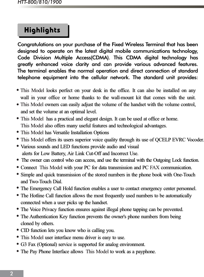
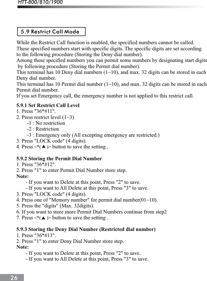
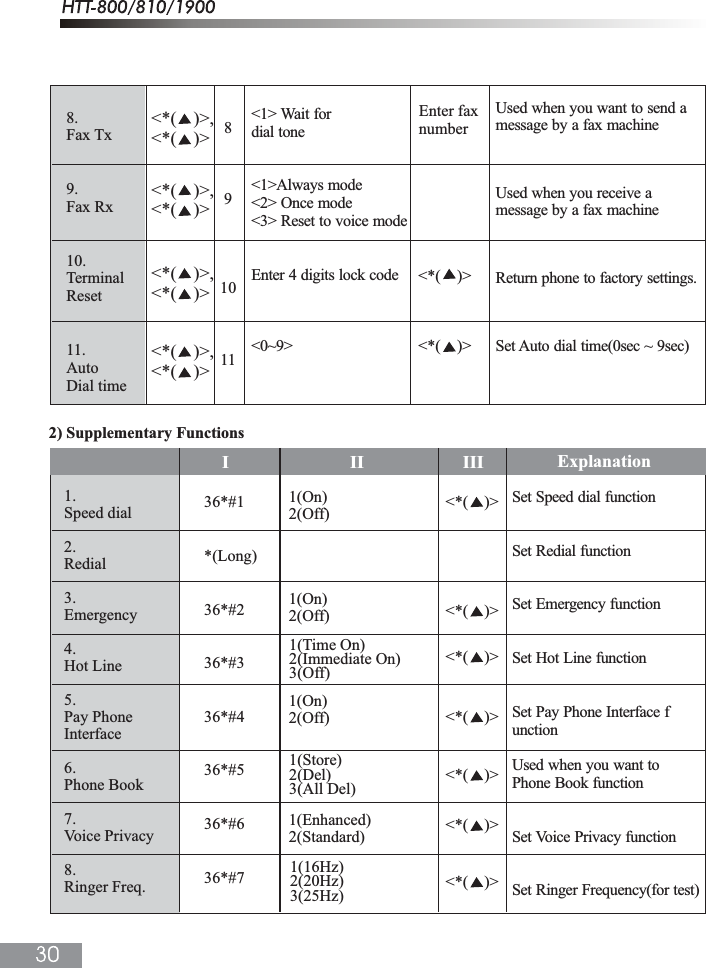
![1. Press "36*#21*" to Emergency Call Hold On 2. Press "36*#22*" to Emergency Call Hold Off5.1.4 Hot Line 1. The Hot Line function is used to make an automatic, quick call to a designated number without dialing. Just pick up the handset, then a call will be made. 2. The Hot Line number should be registered at address 99 in the Phone book. Hotline operates in 2 modes;Timed Hot Line; The call will be made in delayed manner between 4-8 seconds (sending waiting time), depending on your default value, after you pick up the handset. Original default value is 6 seconds. Immediate Hot Line; The call will be made as soon as you pick up the handset. 3. The Hotline function overrides any other functions.1) Hot Line function On / Off 1. Press "36*#31*" to Timed Hot Line On 2. Press "36*#32*" to Immediate Hot Line On 3. Press "36*#33*" to Hot Line Off2) Making a Hot Line Call When a phone number is saved in address [99], and the Hot Line function is set to theTimed Hot Line mode, a call is automatically made, and if the send waiting time (4 ~ 8 seconds) elapses, if the handset is lifted. . If the Hot Line function is set to the Immediate Hot Line mode, and you pick up the handset, the call is made automatically to the number saved in the memory address [99].Note :If the Hot Line function is in the Immediate Hot Line mode, a call may not be made to another number. In this case, to make a call to another number, change the setup mode. Pick up the handset and press <#> within 1 second and go to the setup mode, and deactivate the Hot Line function.This terminal supports the Metering Pulse and the Polarity Reverse for the PCO Interface.If the Metering Pulse is required for the PCO Interface, 2 kinds of frequencies(16KHz, 12KHz) can be supported. (Depend on system) 1. Press "36*#41*" to pay phone Interface on mode. 2. Press "36*#42*" to pay phone Interface off mode.5.2 Pay Phone Interface](https://usermanual.wiki/Hantel/HTT-1900/User-Guide-443530-Page-24.png)
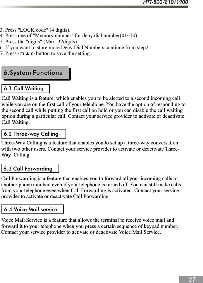
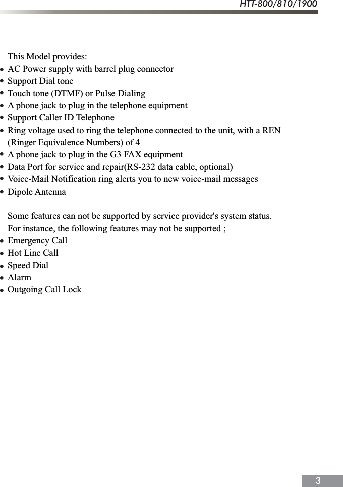
![5.3.1 Storing Phone Numbers 1. Pick up the telephone handset and Press "36*#51" 2. Press the 2 digit address you would like to store the phone number. Suppose the address is <4>, press [04]. 3. Press the phone numbers to be saved digit by digit . 4. When you press button (saving), you will hear a <confirmation beep> indicating the number has been successfully stored.5.3.2 Deleting Phone Numbers1) Deleting a Number 1. Pick up the telephone handset and Press "36*#52" 2. Press the 2 digit address to be deleted. 3. When you press button (saving), you will hear a <confirmation beep> indicating the number has been successfully deleted.2) Deleting All Numbers 1. Pick up the telephone handset and Press "36*#53" 2. When you press button (saving), you will hear a <confirmation sound> indicating all stored numbers have been successfully deleted.This terminal is equipped with voice privacy function to prevent illegal tapping.There are two detailed settings available, <Standard> for regular level voice privacymode and <Enhanced> for reinforced voice privacy mode.<*( )><*( )><*( )><*( )>1. Press "36*#6". 2. Press <1> button for < Enhanced Voice Privacy > mode or <2> button for < Standard Voice Privacy > mode. 3. Press button to save the setting .5.3 Phone Book5.4 Voice PrivacyThis function is used to control the ringer frequency and cadence. Select the frequencyfirst and then select the cadence. Default setting is 20Hz, 1 sec On 2sec Off. 5.5.1 Ringer Frequency Setting5.5 Ringer Frequency & Cadence Control 1. Press "36*#7". 2. Select a desired number from 1(16Hz) , 2(20Hz), 3(25Hz). 3. Press button to save the setting . [Example] If you want to 16Hz, Press 36*#71*<*( )>](https://usermanual.wiki/Hantel/HTT-1900/User-Guide-443530-Page-25.png)
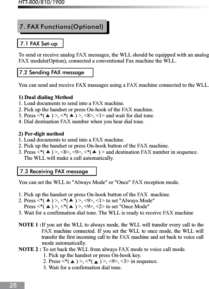
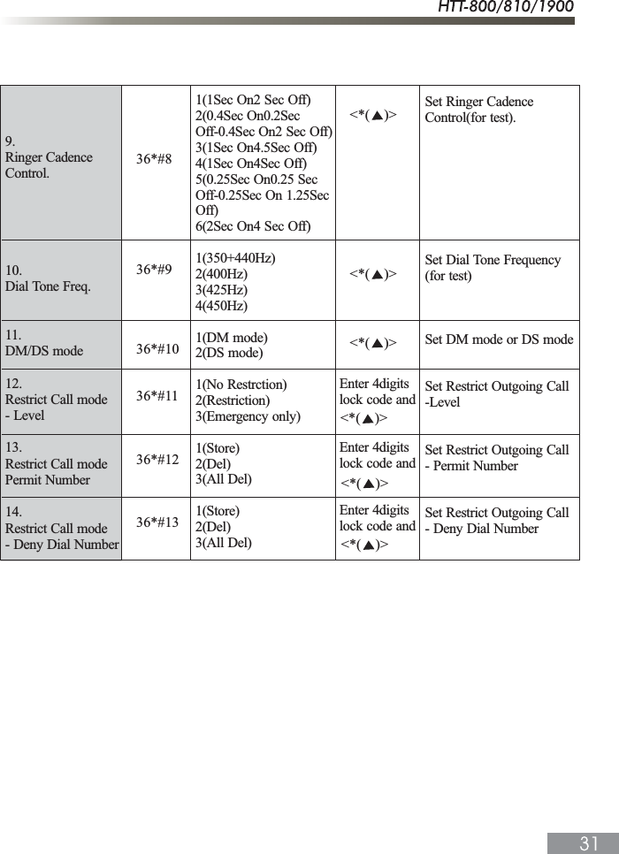
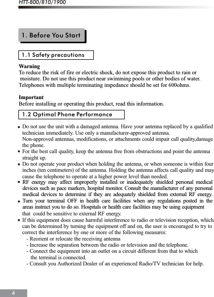
![5.5.2 Ringer Cadence Setting 1. After selecting the frequency, select the cadence. Select a desired number from 1~ 6 to terminate ringer frequency and ringer cadence setting. 2. Press 36*#8. 3. Select a desired number from 1~6. - 1: 1Sec On 2 Sec Off - 2: 0.4 Sec On 0.2 Sec Off - 0.4 Sec On 2 Sec Off - 3: 1 Sec On 4.5 Sec Off - 4: 1 Sec On 4 Sec Off - 5: 0.25 Sec On 0.25 Sec Off - 0.25 Sec On 1.25 Sec Off - 6: 2 Sec On 4 Sec Off 4. Press button to save the setting . [Example] If you want to 2 Sec On 4 Sec Off, Press 36*#86*.This function is used to select the dial sent from the handset. Default setting is350 + 440Hz dual tone. 1. Press 36*#9. 2. Select a desired number from 1(350 + 440Hz), 2(400Hz), 3(425Hz), 4(450Hz). 3. Press button to save the setting . [Example] If you want to 350 + 440Hz, Press 36*#91*.When the terminal receives a hook-flash from the connected telephone device, it willautomatically allow:<*( )><*( )>5.6 Dial Tone Frequency Control5.7 Hook flash1. For producing dial tone again after a phone number has been dialed without connection.2. The use of special cellular services which may be available in your cellular service area.Note: Hook-flash is accomplished in a call through either pressing the dedicated hook-flash key which is available on some phones or through a rapid single press of the hang-up mechanism upon which the handset rests when the phone is hung up.If the telephone equipment remains off-hook , meaning that the handset is left offof its cradle as it would be when you hang up, with no dialing activity for about 60 seconds,a ROH tone emits from the receiver for a period of 60 seconds. After ROH tone, Line5.8 ROH (Receiver Off Hook)Lock Out Tone emits from receiver for a period of 60 seconds.](https://usermanual.wiki/Hantel/HTT-1900/User-Guide-443530-Page-26.png)