Hanwha Techwin SWC306SERVER Web Server Camera User Manual
Samsung Techwin Co Ltd Web Server Camera Users Manual
Users Manual

Webthru SWC 306 User’s Guide
※ This manual is for Webthru SWC 306 Firmware version 1.4.0. If you have later version of
firmware, please download the last updated user’s guide from Samsung Web Camera’s
homepage. (www.webthru.net)
Version 1.0
SAMSUNG TECHWIN CO., LTD.
http://www.webthru.net
System Requirements
For Webthru SWC 306
10 Base-T LAN
(Leased line, xDSL, Cable Modem, ISDN)
For a PC to access Webthru SWC 306
Processor: Pentium II and above
RAM: 64MB and more
OS: Windows 98/NT/2000
Web browser: Internet Explorer 5.0 and above
Screen Resolution: 1024 X 768 pixels and above

2
Webthru SWC 306 User’s Guide
Important Notice
1. Webthru SWC 306 is not weatherproof. Please note the environmental specifications that are included in the
manual. For outdoor usage, equip a weatherproof case to protect the Webthru SWC 306 from water, moisture, or
extreme temperature changes (higher or lower than the specifications noted below). The Webthru SWC 306 can
be cleaned by gently wiping with a clean dry cloth.
2. Be sure to use the DC adapter that is provided by Samsung Techwin Co., Ltd. Connecting Webthru SWC 306
directly to an AC current may cause damage to the Webthru.
3. Be cautious in handling Webthru SWC 306 Physical shock such as dropping the unit may damage the Webthru
SWC 306 and void warranty.
4 The Webthru SWC 306 is made of metal. Be sure that it is fastened tightly during installation to avoid any human
injuries. Make sure to place away from the reach of children.
5. If Webthru SWC 306 does not operate properly, please contact your Samsung Techwin distributor for after sales
service. Unauthorized personnel are prohibited from disassembling the product. Disassembly will automatically
result in void of service warranty.
6. Camera surveillance laws may differ for each country and from province to province. Contact the local region
representative to avoid any violations and to apply for authorized purposes only.
FCC Compliance Statement
Caution : Any changes or modifications in construction of this device which are not expressly
approved the party responsible for compliance could void the user's authority to operate the
equipment.
NOTE : This equipment has been tested and found to comply with the limits for a Class B
digital device, pursuant to part 15 of the FCC Rules. These limits are designed to provide
reasonable protection against harmful interference in a residential installation. This equipment
generates, uses and can radiate radio frequency energy and, if not installed and used in
accordance with the instructions, may cause harmful interference to radio communications,
However, there is no guarantee that interference will not occur in a particular installation. If this
equipment does cause harmful interference to radio or television reception, which can be
determined by turning the equipment off and on, the user is encouraged to try to correct the
interference by one or more of the following measures:
- Reorient or relocate the receivin
g
antenna.
CAUTION
Danger of explosion if battery is incorrectly replaced.
Replace only with the same or equivalent type.
Disposal of used batteries according to the general recommendations against the environmental

3
Webthru SWC 306 User’s Guide
CONTENTS
I. Introduction........................................................................................................................................ 5
II. Product Description ......................................................................................................................... 6
1. Contents....................................................................................................................................... 6
2. Webthru SWC 306 View and Descriptions.................................................................................. 6
3. RS232/RS422/RS485 Descriptions ............................................................................................. 7
4. Description on LED of Ethernet Port ..........................................................................................8
5. Descriptions on DIP Switches ..................................................................................................... 8
III. Webthru SWC 306 Installation Summary, Connection & Placing............................................ 9
1. Installation Summary................................................................................................................... 9
2. Connecting................................................................................................................................... 9
IV. Installing Webthru SWC 306 Setup Program.............................................................................. 9
V. Assigning IP Address and Configuring Administrator’s Condition.......................................... 10
1. Connecting Webthru SWC 306 to a PC..................................................................................... 10
1) Connecting Webthru SWC 306 on Internet or LAN.......................................................... 10
2) Connecting Webthru SWC 306 to a PC............................................................................. 10
2. Assigning IP address and Configuring administrator’s condition with Setup program..............11
1) Starting Setup Program for Webthru SWC 306..................................................................11
2) Configuring Administrator’s Conditions ............................................................................11
3. Assigning IP Address with ARP command.................................................................................11
1) Using ARP in Windows 98 and NT ....................................................................................11
2) Verifying Installation ......................................................................................................... 12
VI.
Accessing Webthru SWC 306 Homepage & Monitoring Real-time Image
............................... 13
1. Starting Web browser................................................................................................................. 13
2. Login page ................................................................................................................................. 13
1) ID and password ................................................................................................................ 13
2) Behind Firewall ................................................................................................................. 13
3) Webthru Active-X for MS Explorer User .......................................................................... 13
4) Webthru Java Applet for Macintosh or Unix system User................................................. 13
5) FAQ ................................................................................................................................... 13
3. Various viewers in Webthru homepage...................................................................................... 14
1) Real time monitoring through Default Single Viewer ....................................................... 14
2) Real time monitoring through Default Multi Viewer ........................................................ 17
3) Real time monitoring through Server Push Viewer ........................................................... 17
VII.
Configuring Administrator’s Condition at Webthru SWC 306 Homepage
.............................. 19
1. Administrator Login .................................................................................................................. 19
1) Accessing through setup program...................................................................................... 19
2) Accessing through Web browser........................................................................................ 19
2. Configuring Administrator’s Condition at Homepage............................................................... 19
1) System Configuration ........................................................................................................ 19
2) User Configuration ............................................................................................................ 20
3) Network Configuration...................................................................................................... 20
4) Dynamic IP registration service for ISDN and xDSL users .............................................. 21
5) How to find a registered Webthru in Webthru Internet homepage .................................... 22

4
Webthru SWC 306 User’s Guide
6) Security Configuration ...................................................................................................... 23
7) Video Configuration ..........................................................................................................26
8) Application Configuration ................................................................................................. 27
9) Pan/Tilt/Zoom Configuration ............................................................................................ 28
10) Serial Port Configuration................................................................................................. 29
11) Digital I/O Configuration................................................................................................. 30
12) Alarm Configuration........................................................................................................ 30
13) User Custom Configuration............................................................................................. 30
14) Goto Viewer Page ............................................................................................................31
Detailed Specifications of Webthru SWC 306 .................................................................................. 32
1. General....................................................................................................................................... 32
2. Network ..................................................................................................................................... 32
3. Mechanical................................................................................................................................. 33
4. Compatible external devices and software ................................................................................ 33
5. Environmental ........................................................................................................................... 33

5
Webthru SWC 306 User’s Guide
I. Introduction
• What is Webthru SWC 306?
The Webthru SWC 306 is a network CCTV camera server solution with an integrated Internet server, image
compression device, flash memory, and many other features. No other hardware is necessary for use. The
Webthru SWC 306 relays video source from a CCTV camera to network and provides real time images over
networks and the Internet. Simply provide power and connect LAN cable and video cable to the Webthru
SWC 306. Webthru SWC 306 utilizes Wavelet image compression and Linux operating system. Wavelet and
Linux enable Webthru SWC 306 to transfer high quality images faster and with a greater degree of reliability
than standard JPEG systems.
• Features and Benefits
Ease of Use – Webthru SWC 306 requires Microsoft Internet Explorer 5.0 (or higher) for use. Windows 2000
is recommended for best results. Connect Webthru SWC 306 to the Internet and it is ready for use.
Compatible with most Systems and Protocols – Webthru SWC 306 supports TCP/IP networking, SMTP,
HTTP and other Internet-related protocols. In addition, the Webthru SWC 306 can be used in mixed
operating system environments, such as Windows, UNIX, Macintosh and OS/2. Webthru SWC 306 also
integrates easily into other Internet/Intranet applications and CGI scripts.
Simple Administration - Webthru SWC 306 can be configured and managed directly from its own web page.
Moreover, as new upgrades become available, it is easy to upgrade Webthru SWC 306 remotely over the
network.
Wavelet Image Format - Unlike many other products that need to fracture image files prior to broadcast, the
Webthru SWC 306 delivers complete, highly compressed pictures in Wavelet format. Wavelet has image
compression rates 30-300% higher than standard JPEG. By utilizing Wavelet, image file sizes are much
smaller than conventional camera servers and Wavelet's image quality is superior to other camera servers as
well. Wavelet can transmit up to 123 frames per second.
External Device Connection - External devices such as IR-sensors, switches, alarm relays and external
video input can be connected to Webthru SWC 306 via six auxiliary Input ports.
User’s Programmable Space – Webthru SWC 306 contains 4.5MB of configurable Flash Memory for user-
programmable and user-configurable space. Because Webthru SWC 306 also acts as a server, this space can
be used to create a personal web page.
Embedded Linux Operating System – Webthru SWC 306 uses an embedded Linux operating system
within its 32bit RISC CPU. Linux is based on UNIX and is one of the most stable operating systems
available. There is very little chance of the operating system crashing.
6
Webthru SWC 306 User’s Guide
II. Product Description
1. Contents
* Unpack and check all the items as below.
Item Description Remarks
Webthru SWC 306 Network server for CCTV camera
Manual Webthru SWC 306 User's Guide Provided on CD
Crossover Cable 1 m crossover cable Red-colored
Direct Cable 2 m direct cable White-colored
Adapter & Power Cable DC 12V, 1.0A
Accessories
brackets for 19-inch rack
bracket for connecting two SWC 306
Screw for bracket
2
1
8
CD ROM title Setup program and manual
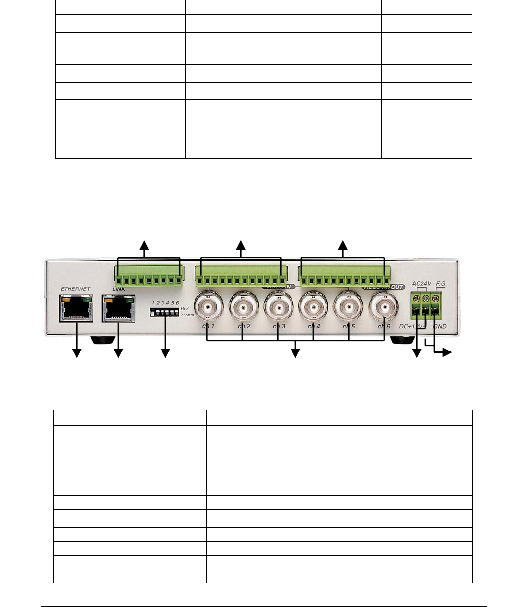
2. Webthru SWC 306 View and Descriptions
Connector Name Description
DIP switch To designate video signal termination of ‘Video Input’ BNC
connector
BNC connector CH1 ~ CH6 To input video signal through a coaxial cable
AC 24V To connect a power supply unit of 24V AC
DC 12V To connect a power supply unit of 12V DC
RJ-45 Ethernet port To connect 10 Base-T Ethernet cable
Link port Stackable up to three boxes only with one IP
RS232/RS422/RS485 To communicate between external devices. These pins are for
devices that satisfy RS-232, RS422, or RS485
Network Link DIP Switch Video In
p
ut AC 24V
DC 12V
RS232/RS422/RS48 Sensor In Alarm

7
Webthru SWC 306 User’s Guide
Sensor In To input video signal through 6 coaxial cables
Alarm Out To output video signal through 6 coaxial cables
3. RS232/RS422/RS485 Descriptions
Connector Name Description
Power To supply power to external devices
Ground To ground cables of power, communication, etc.
RS-232
To communicate between Webthru SWC 306 and external devices such a
CCTV camera or an external modem. These pins are for devices that
satisfy RS-232C protocol, and they are consisted in RX and TX.
RS-422
To communicate between Webthru SWC 306 and a CCTV camera that
satisfies RS-422 protocol. They are half-duflex. It is consisted in R+, R-,
T+, and T-.
RS-485 To communicate between Webthru SWC 306 and a CCTV camera that
satisfies RS-485 protocol. They are consisted in S+ and S-.
P G
RS232
G
RS422
RS485
Rx Tx R+ R- T+ T-
S+ S-

8
Webthru SWC 306 User’s Guide
4. Description on LED of Ethernet Port
Yellow LED: This LED indicates the status of data transmission. After power is supplied, it is on for the first
4-5 seconds and then it goes off. And it blinks continuously when a user access Webthru and Webthru
transmits data.
Green LED: This LED indicates the status of networking. After power is supplied, it is on for the first 1-2
seconds, and then it blinks once at every one second as long as the network is connected.
5. Descriptions on DIP Switches
To configure the function of the six coaxial cable ports at the rear of Webthru SWC 306.
You can configure the relevant channels with each switch. If you connect two CCTV cameras(1Vp-p
/75ohm) to Video Inputs and monitor real time video through 1 and 2 channels, place the two DIP switches
(marked with No. 1 and 2) at 75ohm position.
12345ON
OFF
75 Ω
DIP Switch
6
Hi-Z
75ohm

9
Webthru SWC 306 User’s Guide
III. Webthru SWC 306 Installation Summary, Connection & Placing
1. Installation Summary
z Connect Ethernet and Power to Webthru on local network for configuration.
z Install Webthru Setup Program into a PC on local network.
z Assign an IP address to Webthru and configure administrator’s condition.
z Configure user’s condition.
z Place Webthru, re-connect power and Ethernet.
2. Connecting
z Connect Ethernet line to the Ethernet port in the rear.
z Connect the power supply.
z Confirm that the LED of the Ethernet port blinks.
IV. Installing Webthru SWC 306 Setup Program
z Insert the Webthru Setup disk.
z Drag the Webthru Setup icon onto the desktop.
z Double-click on the icon.
10
Webthru SWC 306 User’s Guide
V. Assigning IP Address and Configuring Administrator’s Condition
1. Connecting Webthru SWC 306 to a PC
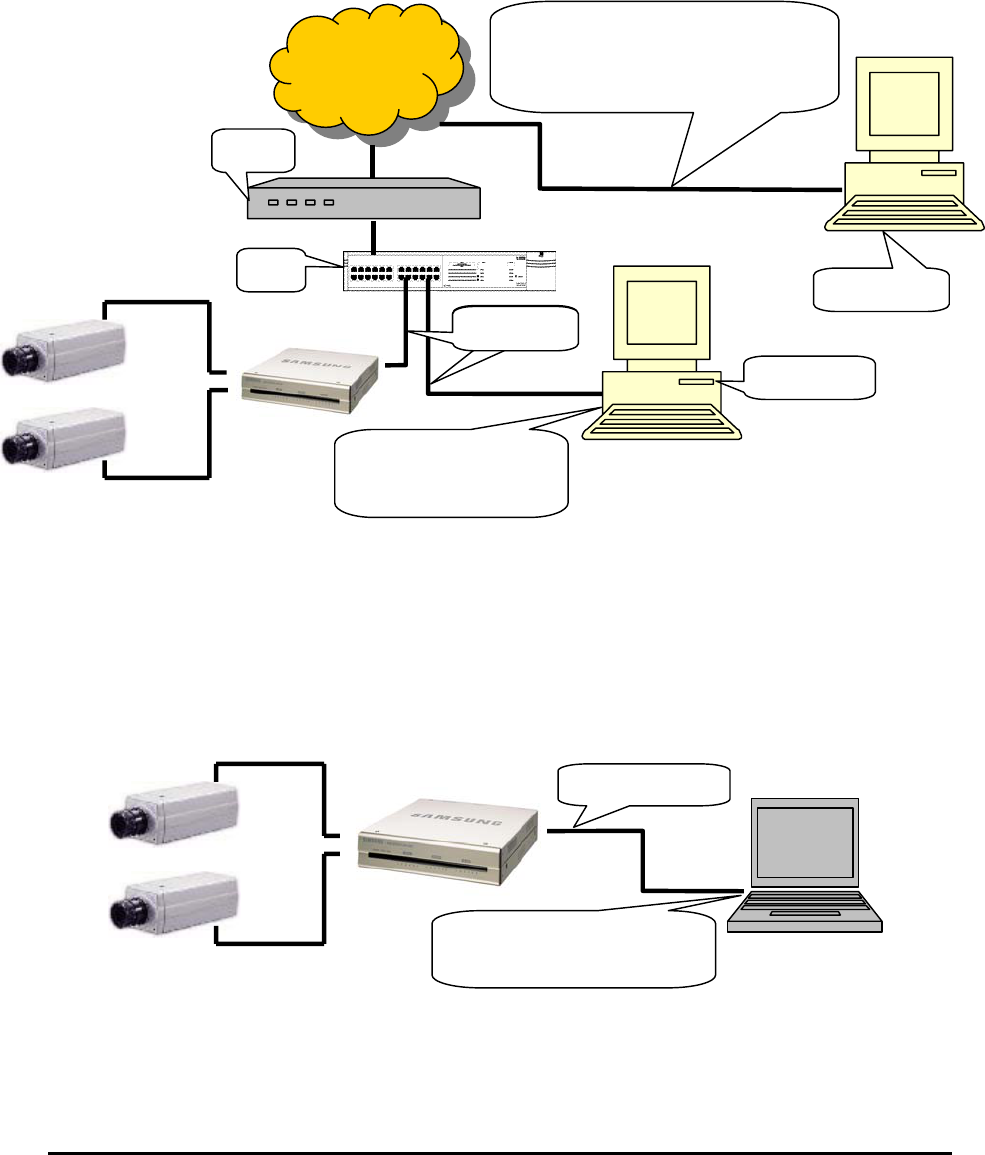
1) Connecting Webthru SWC 306 on Internet or LAN
Use the direct cable (white colored one) to connect Webthru SWC 306 to Internet or LAN. With this
connection, remote users will not be able to access Webthru until local user configures Webthru’s network
setting.
2) Connecting Webthru SWC 306 to a PC
Use the crossover cable (red colored one) to directly connect Webthru SWC 306 to a PC. This connection is
to be used to configure Webthru.
Connect Webthru to a
PC through a HUB.
HUB
Direct cable
Internet
Local User
Remote User
Router
Dedicated line, xDSL line, cable
modem line, and ISDN line are
available.
Crossover cable
Connect Webthru directly to
a PC through LAN ports.
11
Webthru SWC 306 User’s Guide
2. Assigning IP address and Configuring administrator’s condition with Setup program
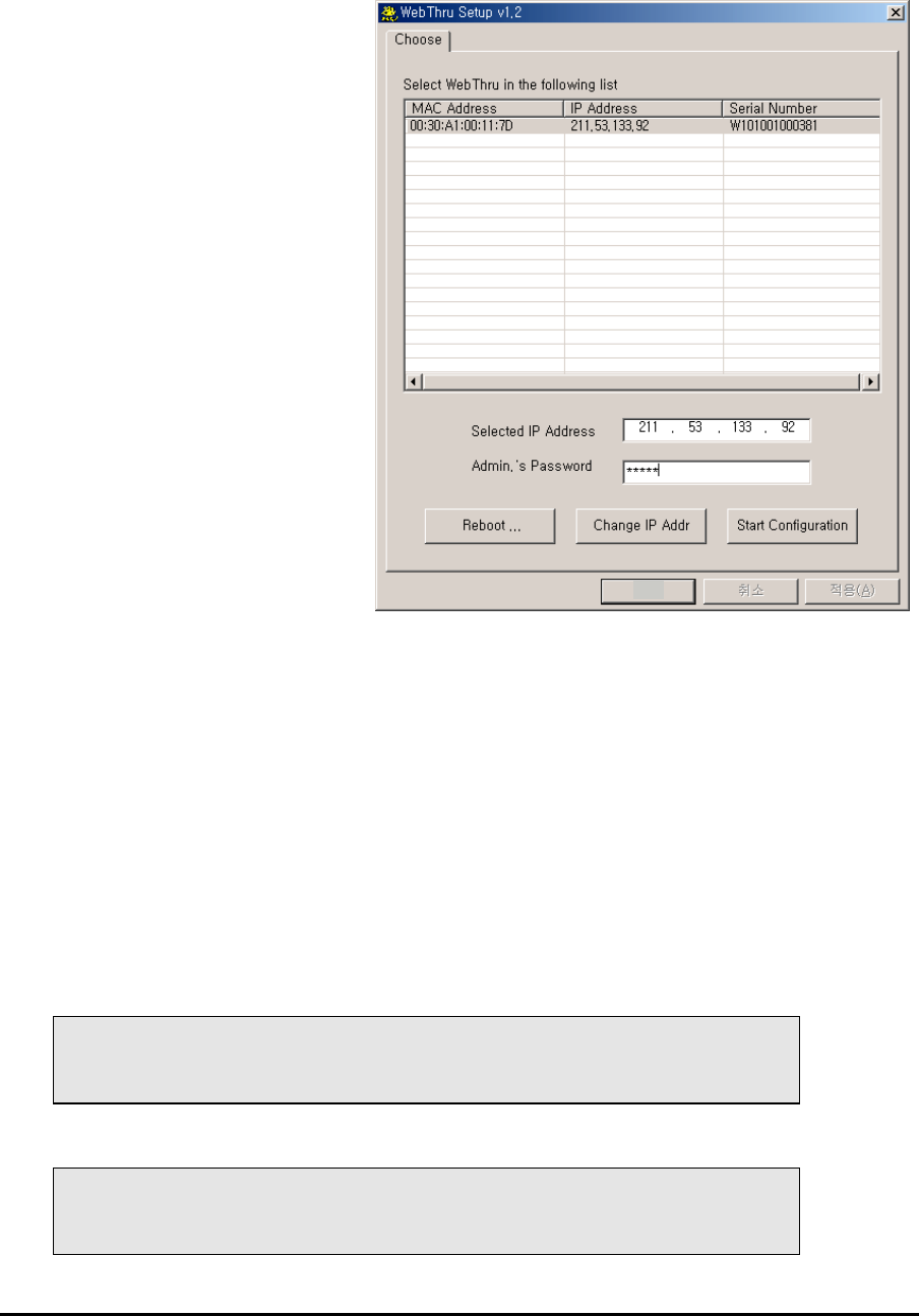
1) Starting Setup Program for Webthru SWC 306
Click the “WebthruSetup.exe” file on
your PC. When the Setup Program is
executed, the setup program detects and
shows every Webthru connected on the
local network.
From the Webthrus listed, select one to
assign a new IP address. (Default is
211.53.133.92) To choose a Webthru,
click on its MAC Address or IP address.
When a Webthru is selected, its IP
address will appear in the ‘Selected IP
Address’ box. Type a password in the
“Admin.’s Password” box to change the
IP address, reboot Webthru, or start
configuration.
The default password is “admin”.
To change the IP address, enter the
Admin.’s password
and click “Change IP Addr.” Enter the new IP address and click “OK.”
The “Reboot” button will reboot the Webthru. This process takes 10-20 seconds.
2) Configuring Administrator’s Conditions
To access the Webthru’s Administrator’s Page from the Setup Menu, enter the admin.’s password and click
the “Start Configuration” button. (For more detailed information, refer to Chapter VII “Configuring
Administrator’s Condition at Homepage”)
3. Assigning IP Address with ARP command
1) Using ARP in Windows 98 and NT
When using Webthru with Windows 98 and Windows NT, follow the steps below.
• Open a DOS window and type the following commands.
arp -s <Webthru IP address> <Webthru Ethernet address>
ping -t <Webthru IP address>
• Example
arp -s 192.168.1.3 00-40-8c-10-00-86
ping -t 192.168.1.3
OK

12
Webthru SWC 306 User’s Guide
2) Verifying Installation
After successfully completing the above procedures, the following message (or similar) will appear on the
screen.
Request timed out
:
Request timed out
Reply from 200.243.232.178: bytes=32 time=2ms TTL=255
Reply from 200.243.232.178: bytes=32 time=2ms TTL=255
Ping statistics for 200.243.232.178:
Packets: Sent = 4, Received = 4, Lost = 0 (0% loss),
Approximate round trip times in milliseconds:
Minimum = 1ms, Maximum = 2ms, Average = 1ms
If the above “ping” reply does not appear, press 'F3' and 'Enter' keys. Normally “Request timed out”
messages appear 7 times before replying properly.
Once the above “ping” reply appears press <Ctrl>+<C> keys to make it stop.
When the “ping” replies stops, data loss may range from 0% to 99%. This is normal. If the statistic shows
‘100% loss’, check the following criterions: (a) network line and connection status are stable; (b) IP address
assigned to Webthru is available; (c) PC and Webthru have the same local network IP address. Same local IP
address of C grade network means that first 3 sets of numbers are the same but the fourth set is different. For
example 192.168.1.2 and 192.168.1.3 are in the same local network. (If there is a ‘Network Mask’ on the
network, this can be an exception. For detailed information on IP, refer to appendix 3)

13
Webthru SWC 306 User’s Guide
VI.
Accessing Webthru SWC 306 Homepage & Monitoring Real-time Image
After assigning Webthru an IP address, the Webthru can be configured within its self- contained homepage
through any standard Web browser on a local network. However access to its Homepage by a remote network
is not possible until gateway address, subnet mask, and broadcast address have been properly assigned.
1. Starting Web browser
Start the web browser and enter the Webthru IP address. This will access the Webthru login homepage.
2. Login page
1) ID and password
The login page allows only registered Webthru users to view images from Webthru. To connect to Webthru
and view real-time images, follow the login procedures.
The default name and password for the user is “guest”. The default Admin username and password is
“admin”. Both may be changed at the Admin page, but neither the ID nor password can be more than nine
characters long.
2) Behind Firewall
If the PC is connected on a network where firewall is, real time image will not be viewed properly because
video TCP port of Webthru is blocked.
To connect Server Push Viewer directly at Webthru homepage, click on ‘Behind Firewall’ menu.
3) Webthru Active-X for MS Explorer User
Systems using Microsoft Explorer require Active-X Control program. The program will usually be installed
automatically when a user accesses a Webthru. A pop-up window will appear for Active-X installation, click
“yes.” If images still do not appear after installation, check the “c:\windows\download program files” folder
(for Windows 2000 NT, the directory is c:\WINNT\download program files). The file name is Web Camera
Server Control. If the file is downloaded, but images cannot be seen, delete the file and re-install.
4) Webthru Java Applet for Macintosh or Unix system User
Java Applet viewer is for systems that do not use MS Windows. Macintosh OS or Unix can be used with the
Java Applet viewer. Java Applet viewer requires java virtual machine that should already be installed on
user’s computer.
5) FAQ
Frequently asked questions and answers are provided here for troubleshooting. If user has other questions,
please contact Samsung Web Camera homepage through http://www.webthru.net.
14
Webthru SWC 306 User’s Guide
3. Various viewers in Webthru homepage
There are 3 viewers for real-time monitoring in the Webthru homepage: Default Viewer, Server-Push Viewer,
and Java Applet Viewer. An administrator may set 3 different viewers as main viewer. (Single Viewer, Multi
Viewer, and Server Push Viewer)
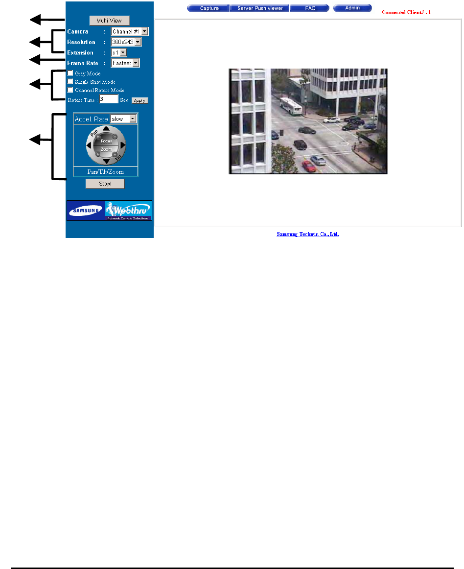
1) Real time monitoring through Default Single Viewer
At default viewer, a user may configure image transmission method and control integrated PTZ mechanism of
a CCTV camera. The PTZ control panel is activated in some seconds depending on network speed.
(1) Single View / Multi View
The “Multi View” allows the monitoring of other images from additional cameras connected to the Webthru.
If you press the “Multi View”, you can view six images simultaneously. Please note that transmission speed
cannot exceed 30 fps, and additional images will make overall transmission speed slow. “Single View”
monitors a single channel. Click on the appropriate button for single view or multi view.
(2) Image Control
Resolution
Select the level of resolution from 5 levels (720x486, 720x243, 360x243, 180x121, 90x60). Higher-resolution
images are larger file sizes and are transmitted at slower speed.
Expansion
Expansion enlarges the image from 1X to 4X. However, expansion (2X to 4X) does not increase image’s
resolution, hence the clarity of an expanded image will not be as good as the original.
Frame rate
To control image transmission speed. “Fastest,” will receive images at the fastest speed possible within the
network environment. The transmission speed is dependent on the network line’s capacity and user PC’s
(1)
(2)
(3)
(4)
(5)
15
Webthru SWC 306 User’s Guide
performance. Webthru can transmit up to 30 frames per second, but total frames transmitted by all 6 channels
cannot surpass the maximum rate of 30 fps.
(3) Camera selection
Select cameras to monitor. User may select one specific camera or all 6 cameras.
(4) Transmission Control Gray Mode On
Images are displayed in black and white. Images can be transmitted at a higher speed under gray mode.
Single Shot Mode On
When this button is clicked, one frame of image is reproduced. Therefore, no other images may be viewed.
Channel Rotate Mode On
Images are viewed one after another as channel number. It may be configured by second.
(5) Play Control Pan/Tilt
To move the direction of external camera to where to want to see.
Zoom
To zoom the image in and out.
Focus
To control and optimize the image’s focus.
Accel. Rate
To control the moving speed of the Pan / Tilt mechanism. There are three settings. “Accel.” does not control
zooming speed. This can be adjusted with the mouse. By clicking the right mouse button on the image, a pop-
menu with five options will appear. The “Focus Sensitivity” controls zooming speed from level 1 to 10.
Play/Stop: Webthru generates and transfers the real-time images as soon as it is accessed. To stop transferring
images, click the “Stop” button. To resume transfer, click “Play” button.
(6) Other Function Buttons
Capture
To save a frame of still image transmitted from Webthru. A still image can be saved as a format of bitmap
(*.bmp) or Wavelet method file (*.eye). Wavelet compression image file can be decompressed and
reproduced on Internet browsers such as Explorer. Another method to capture a still image is: Place the mouse
on the image; Click the right mouse button; Select the “Save As File” option from the pop-up menu.
Server-Push Viewer
To go to the server-push viewer.
FAQ
It lists frequently asked questions and answers.

16
Webthru SWC 306 User’s Guide
Admin
To access administration page. (Refer to Chapter VII ‘Configuring Administrator’s Configuration at
Homepage’)
(7) Convenient pop-up menu
A small window of 5 menus appears when you click the right button of the mouse. However only users who
are permitted can utilize the functions such as ‘Quality Box’, ‘Focus Sensitivity’, and ‘Image Quality’. ‘Image
Info’ and ‘Save As File’ menus are permitted to any user. And the results of the four functions except ‘Save
As File’ are to be affected in every image that is transmitted to all users. (For detailed information, refer to
‘User Configuration’ in Chapter VII). And in server push viewer, only ‘Image Info’ and ‘Save As File’ menus
are supported.
Image Info
You may decide the color (black or white) of the information that is shown on the left top of the image. And
you may leave out the information.
Quality Box
This is to set a certain area clear and remained area dull. You can overcome insufficient network bandwidth
with this function, because the file size is reduced with unfocused area. Quality Box is to be set like under
written description.
• Choose ‘New QBOX’ button.
• Place mouse cursor on a certain point of real time image where to start QBOX.
• Click and drag the mouse point.
You can also re-use previous QBOX area to focus again by clicking ‘Enable QBOX’. ‘Disable QBOX’ is to
finish. The image activated Focusing Area function is seen in the right. The image quality of outer area of
QBOX is to be set with ‘Ambient Level’ menu. The level is from 1 to 5. If you select ‘Level 1’, the quality is
similar to focused area. And if you select ‘Level 5’, the unfocused area is shown dark. A user who has ‘Video
control’ right may utilize this menu.
Focus sensitivity
You may configure movement degree of zoom mechanism. The sensitivity is from Level 0 to Level 9. By
selecting ‘Level 9’, user zooms in or out at the largest degree. A user who has ‘PTZ control’ right may utilize
this menu.
Image quality
It is to set image quality. The image quality is from Level 0 to 9. If user chooses the ‘Level 9’, Webthru sends
the finest image. However, transmission frame rate will be reduced because of large sized data. If user
chooses ‘Level 0’, Webthru sends dullest image but fast. A user who has ‘Video control’ right may utilize this
menu.
Save As File
It is to save a frame of still image as an electric file. A still image can be saved as bitmap (*.bmp) file or
Wavelet format file (*.eye). Wavelet formatted image file is to be reproduced on Internet Explorer as long as
the PC is installed Active-X program. The very image that is shown at the moment when you click the menu
is saved.
17
Webthru SWC 306 User’s Guide
(8) Placing a company logo
The Webthru logo, located on the left bottom of the viewer, can be replaced with a different company logo.
2) Real time monitoring through Default Multi Viewer
(1) Single View / Multi View
You can select a mode between single view and multi view. The button is toggled between the two functions.
(2) Play/Stop
Webthru generates and transfers six real-time images as soon as it is accessed. To stop transferring images,
click the “Stop” button. To resume transfer, click “Play” button.
(3) Camera selection
Select the camera to configure a frame rate.
(4) Frame Rate
Control image transmission speed. “Fastest,” will receive images at the fastest speed possible within the
network environment. The transmission speed is dependent on the network line’s capacity and user PC’s
performance. Webthru can transmit up to 30 frames per second, but total frames transmitted by all 6 channels
cannot surpass the maximum rate of 30 fps.
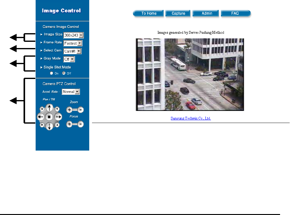
3) Real time monitoring through Server Push Viewer
If Webthru is installed on a network where firewall is, you may access Webthru through server-push viewer
to monitor real-time images.
(1) Image Control
Extension menu is not supported.
Image Size
Select the level of resolution from 5 levels (720x486, 720x243, 360x243, 180x121, 90x60). Higher-
resolution images are larger file sizes and are transmitted at slower speed.
(1)
(2)
(3)
(4)

18
Webthru SWC 306 User’s Guide
Frame Rate
Control image transmission speed from 5 levels (fastest, 10fps, 5fps, 3fps, 1fps). “Fastest,” will receive
images at the fastest speed possible within the network environment. The transmission speed is dependent on
the network line’s capacity and user PC’s performance.
(2) Camera
Select cameras to monitor. User may select one specific camera to monitor real-time image.
(3) Transmission Control
On this viewer, “Channel Rotate Mode On” menu is not available.
Gray Mode
Images are displayed in black and white. Images can be transmitted at a higher speed under gray mode.
Single Shot Mode
When this button is clicked, one frame of image is reproduced. Therefore, no other images may be viewed.
(4) Play Control
Pan/Tilt: To move the direction of external camera to where to want to see.
Zoom: To zoom the image in and out.
Focus: To control and optimize the image’s focus.
Accel. Rate: To control the moving speed of the Pan / Tilt mechanism.
(5) Convenient pop-up menu
‘Quality Box’, ‘Focus Sensitivity’, and ‘Image Quality’ menus are not supported.
Image Info
You may decide the color (black or white) of the information that is shown on the left top of the image. And
you may leave out the information.
Save As File
It is to save a frame of still image as an electric file. A still image can be saved as bitmap (*.bmp) file or
Wavelet format file (*.eye). Wavelet formatted image file is to be reproduced on Internet Explorer as long as
the PC is installed Active-X program. The very image that is shown at the moment when you click the save
button is saved.
(6) To Home
This button returns to the default viewer.
(7) Capture
This button is to save a frame of still image transmitted from Webthru. This function is the same with ‘Save
As File’ menu.
(8) Admin
It is to access administration page. (Refer to Chapter VII ‘Configuring Administrator’s Configuration at
Homepage’)
(9) FAQ
User may refer FAQ for trouble-shooting in installing or running Webthru.
19
Webthru SWC 306 User’s Guide
VII.
Configuring Administrator’s Condition at Webthru SWC 306 Homepage
This page is for administrator. Administrator may control operating status remotely. This page can be
accessed through Setup program by clicking ‘Start Configuration’ button.
1. Administrator Login
1) Accessing through setup program
Select Webthru by clicking on the MAC address or IP address. Then type in the administrator’s ID and
password (Default ID and password are ‘admin’), and click “Start Configuration” button. The setup program
automatically connects to the Admin page of Webthru Homepage.
2) Accessing through Web browser
On Web browser, a user may access Webthru login page with its IP address. In the login page, a user may key
in administrator’s ID and password or a normal user’s ID and password. With any of ID and password, the
user may access real time image viewer page.
2. Configuring Administrator’s Condition at Homepage
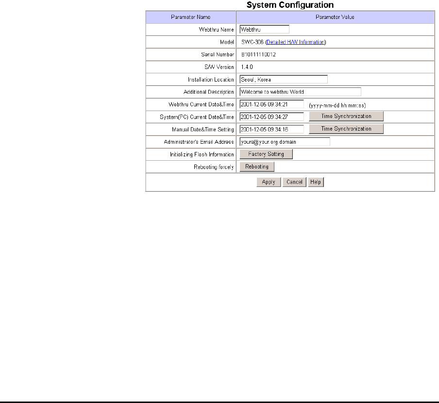
1) System Configuration
This page is to set name, date &
time, location, and description
of one’s Webthru. Model, serial
number, and software version
appear automatically.
(1) Webthru Name
The name is to be used to
register the Webthru on a
certain server, if dynamic IP
address is used. Therefore it is
very important to set a proper
name for user to find the
Webthru in the dynamic IP
registration list. (For detailed information, refer to ‘Dynamic IP Registration Service for ISDN, xDSL User’)
(2) Model
By clicking ‘Detailed H/W Information’, administrator may view the detailed hardware information such as
maximum numbers of channel, serial port, digital input, digital output, etc. The model name is marked
automatically.
(3) Installation Location & Additional Description
The information is to show in a dynamic IP registration list.
(4) Date & Time
There are three date & time menus. In “Webthru Current Date & Time” panel, the date and time that is set in
the Webthru appears. In “System (PC) Current Date & Time” panel, the same date and time that is set in
user’s PC appears. To synchronize the Webthru and PC date and time, an administrator can click the “Time
20
Webthru SWC 306 User’s Guide
Synchronization” button. The “Manual Date & Time” panel allows the user to set date and time.
(5) Administrator’s E-mail Address
In this panel, administrator records one’s e-mail address. If administrator put a ‘contact’ menu of e-mail
communication on real time image viewer page, the linked e-mail address to the ‘contact’ menu is to be
synchronized with this. So administrator can keep up e-mail address easily.
(6) Initialize Flash Info
This will initialize almost all the information saved on Flash Memory. However Date & Time, Model, Serial
Number, and IP configuration of “System Configuration”, and Video Signal Type of “Video Configuration”
menus will not be changed.
(7) Rebooting
If Webthru has any problems, administrator can reboot it without adjusting power supply. This button works
as on/off switch.
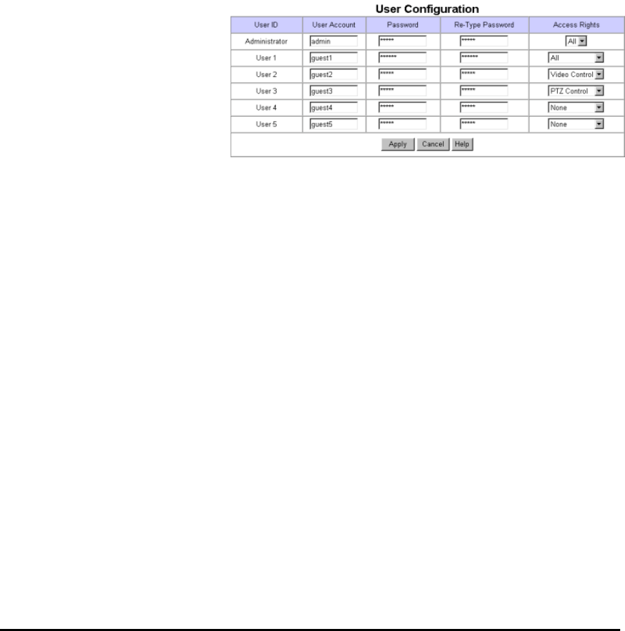
2) User Configuration
This page is to configure IDs and
passwords of an administrator and 5
users.
(1) User Account
There are one administrator’s
account and 5 users’ accounts.
Account name can be changed.
(2) Password
If you want to open your Webthru to everyone, you may not change default user’s ID and password. However
you should change administrator’s ID and password as unique ones.
(3) Access Rights
Administrator may give or take users’ right of PTZ control and video control. With default setting,
administrator has both right of PTZ control and video control and normal user doesn’t have any right.
• Video control: This is to control pop-up menus such as image quality level and QBOX settings.
• PTZ control: This is to control ‘Focus Sensitivity’ in pop-up menu and to control PTZ mechanism of a
CCTV camera.
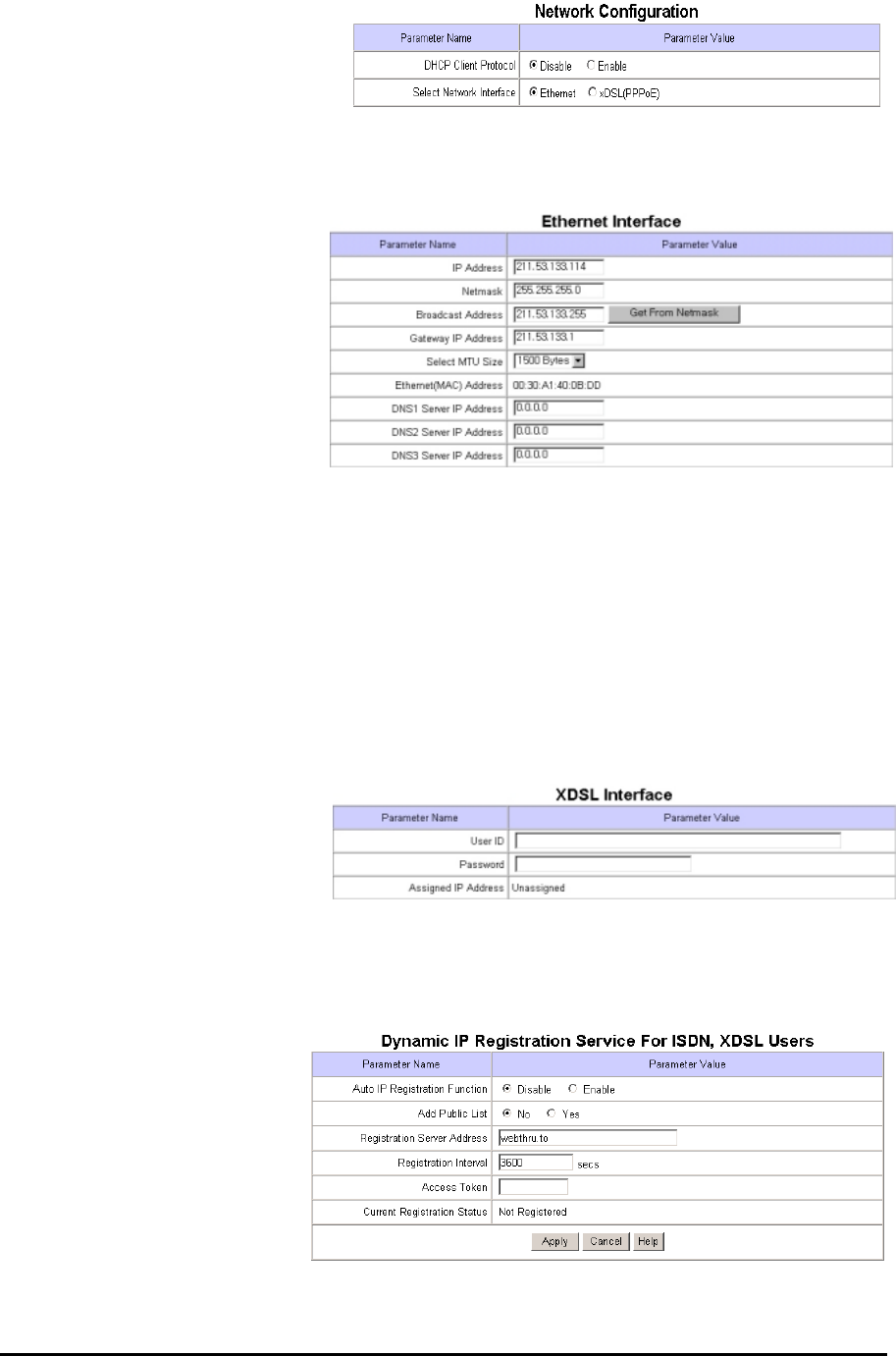
3) Network Configuration
This page is to define network type and set network addresses of Webthru.
(1) DHCP Client Protocol
DHCP (Dynamic Host Configuration Protocol) is to manage host address on a network. With this protocol,
every host on a LAN may share limited official IP address for Internet access. In other words, every host on a
LAN may lease official IP address from DHCP server temporarily.
(2) Select Network Interface
This is to select proper network interface with which Webthru is connected.
21
Webthru SWC 306 User’s Guide
If Webthru is connected with Internet
dedicated line, cable modem line or on
LAN environment, you should select
network interface as ‘Ethernet’.
If Webthru is connected on xDSL line that needs PPPoE process to connect on Internet, administrator should
select ‘xDSL (PPPoE)’.
(3) Ethernet Interface
Administrator may configure IP
address, subnet mask, broadcast
address, gateway address, and DNS
addresses of Webthru. For broadcast
address, administrator may set it
automatically by clicking ‘Get From
Netmask’ button after assigning IP
address and subnet mask.
This interface is mainly used for
Internet dedicated line and LAN, and sometimes for xDSL line as it is explained on ‘DHCP Client Protocol’
setting.
MTU Size: Depending on network type, administrator may set data packet size with this menu to utilize the
network at most effectively.
DNS Server IP Address: This is used when you register your Webthru on dynamic IP registration list of
SWR (Webthru Registration Server). SWR has its domain name of ‘Webthru.to’ and the domain name is
registered on DNS servers on the world.
(4) xDSL Interface
If Webthru is connected on xDSL
line and needs PPPoE process,
administrator should select network
interface as ‘xDSL (PPPoE)’. And
administrator should configure user ID and password for PPPoE. ID and password may be acquired from the
ISP that installed the line.
4) Dynamic IP registration service for ISDN and xDSL users
This page is to register Webthru
on dynamic IP registration server.
If Webthru is installed on a
network of dynamic IP address
(floating IP address),
administrator should register the
Webthru on dynamic IP
registration server to give
common users simple connectivity. If not, no one can access the Webthru through Web browser. It is because
that no one knows IP address which one can access the Webthru with.

22
Webthru SWC 306 User’s Guide
To solve the problem, Samsung Techwin runs a server making a list of Webthrus that have dynamic IP
addresses. On the server, Webthru registers its information such as name, location, and description, so those
common users may detect a certain Webthru. Name, location and description are assigned at ‘System
Configuration’ page. If administrator does not change them, the Webthru will register default information on
the list, and it will be very difficult to point out and access a certain Webthru. The list is on an Internet
homepage of Webthru (www.webthru.to).
(1) Auto IP Registration Function
Administrator may register one’s Webthru by enabling ‘Auto IP Registration Function’. Registration process
is that Webthru detects IP addresses from DHCP server and informs the detected IP addresses to dynamic IP
registration server.
(2) Registration Server Address
This is to configure a server address for registration. The registration server to be used for Dynamic IP
registration should be installed proper S/W, developed by Samsung Techwin Co., Ltd.
(3) Registration Interval
Dynamic IP addresses are commonly used with xDSL, ISDN or Cable Modem lines. In order to maintain
continuous connectivity, user should reset the ‘Registration Interval’ at a shorter time interval than the default
value.
(4) Add Public List
There are two registration systems. One is to register on a public list and the other is on a private list.
(5) Access Token
Access token is a password and it is used when you register your own Webthru on a list ‘User’s Webthru’ out
of all Webthrus on SWR(Webthru Registration Server).
5) How to find a registered Webthru in Webthru Internet homepage
On Webthru Internet homepage (www.webthru.to), there are menus to find the Webthru that is registered on
SWR (Webthru Registration Server).
(1) Sign up membership
To search your Webthru out of a public list or a private list, sign up membership first. You may sign up on the
server through ‘Membership’ menu.
(2) Finding Webthru from public list
To access Webthru that is registered on public list, you may find it through ‘Service’ menus. Once click
‘SWR’ menu, you may find ‘SWR (Webthru Registration Service) Webthru list’ on SWR page that is a main
page of the ‘Service’ menu.
(3) Finding Webthru from private list
To access Webthru that is registered on private list, you should make your own Webthru list before. You may
make the list through ‘My Webthru’ menu.
My Webthru List: You may maintain your own Webthru registering it on this list. When you login this

23
Webthru SWC 306 User’s Guide
homepage, SWR (Webthru Registration Server) detects and shows all the Webthrus that you listed appear on
your own list.
Webthru Add & Delete: This menu is to append a certain Webthru on your own list. You may append
Webthru on your own list as follows.
• Key in serial number(e.g. W100000000000), MAC address(e.g. 00:00:00:00:00:00), and access token
of a certain Webthru in the box.
• Click ‘Append’ menu.
• SWR (Webthru Registration Server) searches a corresponding Webthru with the conditions from both
‘Public List’ and ‘Private List’ and registers the Webthru on your own list.
6) Security Configuration
This is to filter a certain IP addresses
from accessing Webthru based on
network masking.
(1) IP/Subnet Filtering Mode
You may allow or deny a certain user
to access your Webthru with enabling
this menu.
Default Policy
This is to decide the principle of
‘IP/Subnet Filtering Mode’ between
allow and deny.
How to register allowed/denied user in the list
Network masking is to mask network ID for every existing IP address in the world. Therefore the IP addresses
that have the same network ID are to be applied with a command of ‘Allow’ or ‘Deny’. The masked bits are
considered as network ID.
Note: To explain and understand easily on IP address, the first byte of IP address is marked as X1 in this
manual. And X2 is for the second byte, X3 is for the third byte, and X4 is for the fourth byte.
IP address is constructed as follows.
IP address construction in binary number of each bit
xxxxxxxx (8 bit): X1 xxxxxxxx (8 bit): X2 xxxxxxxx (8 bit): X3 xxxxxxxx (8 bit): X4
2726252423222120272625242322212027262524232221202726252423222120
E.g. IP address in binary: 11000000. 10101000. 00000001. 00001101 (It is equal to 192.168.1.13)
* Binary number 1 means to take the equivalent decimal number (27, 25, etc) and 0 means to disregard it.
IP address construction in decimal number of each byte
xxx (0-255: 1 byte): X1 xxx (0-255: 1 byte): X2 xxx (0-255: 1 byte): X3 xxx (0-255: 1 byte): X4
128 64 32 16 8 4 2 1 128 64 32 16 8 4 2 1 128 64 32 16 8 4 2 1 128 64 32 16 8 4 2 1

24
Webthru SWC 306 User’s Guide
E.g. IP address in decimal: 192. 168. 1. 13 (It is equal to 11000000. 10101000. 00000001. 00001101)
* Binary number 1 means to take the equivalent decimal number (27, 25, etc) and 0 means to disregard it.
Network masking point is to be expressed with decimal number from 0 to 31. IP address is consisted in 4
bytes. 4 bytes are 32 bits. Network is to be masked on every bit from the first bit to the 32nd bit. Masked bit is
marked with binary number ‘1’, and the corresponding bits out of provided IP address are defined as network
ID for IP filtering.
Network masking point (0 to 31)
123456789101112131415161718192021222324252627282930310
E.g. Network masking on the 8th bit (8): 11111111. 0000000. 00000000. 00000000 (255.0.0.0)
E.g. Network masking on the 16th bit (16): 11111111. 11111111. 00000000. 00000000 (255.255.0.0)
E.g. Network masking on the 24th bit (24): 11111111. 11111111. 11111111. 00000000 (255.255.255.0)
E.g. Network masking on the 32nd bit (0): 11111111. 11111111. 11111111. 11111111 (255.255.255.255)
According to masking point, masked network ID is to be different out of the same IP address. For example, if
IP address is described as 192.168.1.13 (11000000.10101000.00000001.00001101) with masking point 24
(255.255.255.0), the IP addresses whose IP address is consisted with
‘11000000.10101000.00000001.xxxxxxxx’ (28 (256) pieces of IP addresses) will be allowed or denied from
Webthru.
If you describe an IP address as 192.168.1.13 and put masking point 26 (255.255.255.192), the masked bits
are the first 26 digits and network ID masked as ‘11000000.10101000.00000001.00’. In this case, the IP
addresses whose IP address is consisted with ‘11000000.10101000.00000001.00xxxxxx’ (26 (64) pieces of IP
addresses) will be applied with a command of ‘Allow’ or ‘Deny’.
Though masking point is to be any bit out of 32 bits, it is common to point on the bits of host ID part. If the
masking point is placed on network ID part, the range is expanded compared to the provided IP address.
Network class is divided as follows. D and E class networks are not to be used by normal user.
Class Decimal number of X1 byte Network ID Host ID
A 0 to 127 X1 X2, X3, X4
B 128 to 191 X1, X2 X3, X4
C 192 to 223 X1, X2, X3 X4
D 224 to 239 For Multicasting utilization
Applied IP address number according to masking point
1 2 3 4 5 6 7 8 9 10111213141516171819202122232425262728293031 0
231 230 229 228 227 226 225 224 223 222 221 220 219 218 217 216 215 214 213 212 211 210 29282726252423222120
E.g. Masking point 8: 224 pieces of IP addresses are applied
E.g. Masking point 16: 216 pieces of IP addresses are applied
E.g. Masking point 24: 28 pieces of IP addresses are applied
E.g. Masking point 0: 20 pieces of IP address (itself) is applied

25
Webthru SWC 306 User’s Guide
E 240 to 255 Reserved for specific utilization
In C class network, the applied number of IP addresses with network masking is as below when you mask on
host ID part (X4: the fourth byte).
Masking on X4 Byte Remark Host ID
number
25 26 27 28 29 30 31 0 Masking Point
128
(128)
64
(192)
32
(224)
16
(240)
8
(248)
4
(252)
2
(254)
1
(255)
Decimal Number
(Accumulated Value)
Masked Free Free Free Free Free Free Free 7 digits are free 27 = 128
Masked Free Free Free Free Free Free 6 digits are free 26 = 64
Masked Free Free Free Free Free 5 digits are free 25 = 32
Masked Free Free Free Free 4 digits are free 24 = 16
Masked Free Free Free 3 digits are free 23 = 8
Masked Free Free 2 digits are free 22 = 4
Masked Free 1 digits are free 21 = 2
Masked No free digit 20 = 1
The most common case is to make subnet through network masking, and it is to divide a network into some
smaller network. If provided IP address is 192.168.1.2, you may divide the whole network into 2 sub-
networks and allow or deny only the IP addresses that belong to one of sub-networks.
With setting as follows, The IP address of 192.168.1.2 is divided into two sub-networks and allow for the IP
address out of the first sub-network to assess Webthru.
• Default Policy: Deny
• IP address: 192.168.1.2
• Masking: 25 (255.255.255.128)
• Then only the IP addresses from 192.168.1.0 to 192.168.1.127 are to access Webthru, while the IP
addresses from 192.168.1.128 to 192.168.1.255 and any other IP address are to be denied accessing
Webthru.
Changing IP address can reverse the result. If you set IP address as 192.168.1.130, only the IP addresses from
192.168.1.128 to 192.168.1.255 are to access Webthru. And the IP addresses from 192.168.1.0 to
192.168.1.127 and any other IP address are to be denied accessing Webthru.
You may refer below table to figure out masking point from network information that is given from your ISP
or network administrator.
Masking Point Masked bit (Network ID) Netmask in decimal number
1 The first bit 128.0.0.0
2 From the first bit to the second bit 192.0.0.0
3 From the first bit to the third bit 224.0.0.0
.
8
9
.
16
.
From the first bit to the 8th bit
From the first bit to the 9th bit
.
From the first bit to the 16th bit
.
255.0.0.0
255.128.0.0
.
255.255.0.0
26
Webthru SWC 306 User’s Guide
17
.
From the first bit to the 17th bit
.
255.255.128.0
.
24 From the first bit to the 24th bit 255.255.255.0
25 From the first bit to the 25th bit 255.255.255.128
26 From the first bit to the 26th bit 255.255.255.192
27 From the first bit to the 27th bit 255.255.255.224
28 From the first bit to the 28th bit 255.255.255.240
29 From the first bit to the 29th bit 255.255.255.248
30 From the first bit to the 30th bit 255.255.255.252
31 From the first bit to the 31st bit 255.255.255.254
0The 32
nd bit 255.255.255.255
* Masking on 32nd bit has the same effect as masking none, and in Webthru 0 instead of 32 is used.
Masking 32 bits means that all the 32 bits are network ID, and masking none means that all the 32 bits
are host ID. Therefore masking all the 32 bits or none means that the provided IP address itself is applied
with a command of ‘Allow’ or ‘Deny’.
If you want to allow only the IP addresses from 192.168.1.61 to 192.168.70, you may set as bellows.
Default Policy Deny
IP address 192.168.1.60 Masking 30 Policy Allow
IP address 192.168.1.60 Masking 0 Policy Deny
IP address 192.168.1.64 Masking 29 Policy Allow
IP address 192.168.1.71 Masking 0 Policy Deny
* The IP addresses in black squares can be any IP address of the sub-networks. In the first square,
192.168.1.60 to 192.168.1.63 is to be assigned. And in the second square 192.168.1.64 to 192.168.1.71 is to
be assigned.
(2) Image Encryption Mode
Administrator may restrict people to receive images from one’s Webthru, even though people accessed it. If
‘Image Encryption Mode’ is enabled and a pin number is assigned, people have to key in the assigned pin
number to see image after accessing Webthru image viewers.
‘Security Configuration’ is a double-checking function to control accessibility, utilizing ‘User Account
Configuration’ at the same time.
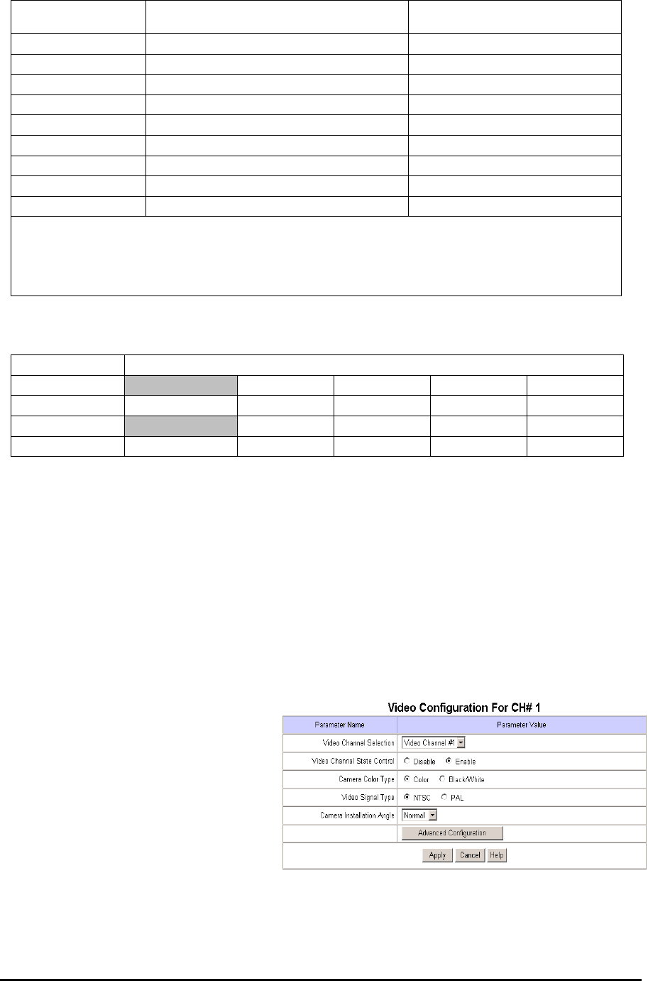
7) Video Configuration
This page is to configure every channel with
various conditions.
(1) Video Channel Selection
To select which video channel to configure.
In the list, there are 6 video channels.
(2) Video Channel State Control
It is to determine which channels will be enabled to send image signals to the image viewer. If a channel with
an external source is disabled, no image will appear in the image viewer. However, if a channel without an
external source is enabled, the overall transmission speed will go down and no image will appear. To view an
image from an external source, the channel with the source must be enabled.

27
Webthru SWC 306 User’s Guide
(3) Camera Color Type
It is to define whether images from a camera are color or Black/White (B/W). This will not change a camera’s
original character (color cameras can be viewed in B/W or color, but they are still “color” cameras). Rather,
this is to help define external cameras, and provide information to Webthru.
(4) Video Signal Type
It is to define whether the signals of external CCTV cameras are ‘NTSC’ or ‘PAL’.
(5) Camera Installation Angle
Webthru can always show images in right angle regardless of camera’s installation position. If camera is
located on the wall upside down, user can adjust image angel by selecting ’90 deg.’ or ‘270 deg.’
(6) Advanced Configuration
Calibration Parameters
Administrator can manipulate screen settings by adjusting brightness, contrast, hue, saturation, horizontal line
shift, and vertical line shift from the menu. With ‘Video Gain’ menu, the image may be optimized without
adjusting each value of other menus. However ‘Video Gain’ is not supported currently. It is to be supported in
near future.
Caption Display Options
Administrator can configure caption on real time image with display options such as color and contents.
Caption is to be made of time information, channel information, and additional explanation (user defined
string).
Visual Setting Parameters
Administrator can configure QBOX and image quality level with aid of real time image. Place the mouse
curse on real time image and click the right button, and pop-up menus will be viewed.
z QBOX Parameters: Administrator sets QBOX area with a mouse to ‘click and drag’. With ‘Ambient
Level’ menu, Administrator may set quality level of unfocused area in the image (out of the focused range).
z Image Quality Level: Administrator chooses image quality level from 0 to 9. Level 9 is the best quality.
But transmission speed will be reduced because of larger sized data. The image level inside the ‘QBOX’ is
the same level as is selected in this menu.
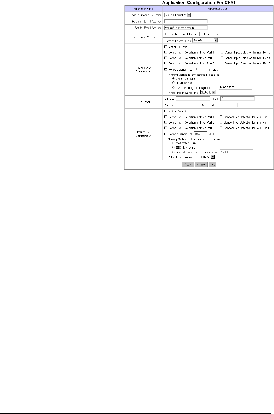
8) Application Configuration
This page is to configure e-mail and file sending functions.
(1) Select Video Channel
It is to select a video channel for configuration.
(2) Recipient E-mail Address
This is to designate a person to receive E-mail.
(3) Sender’s E-mail Address
This is to put a person’s e-mail address that is considered as the e-mail sender.
The e-mail sender can be a person who should take care of the situation when events occur. E-mail will be
28
Webthru SWC 306 User’s Guide
delivered to a person who is defined as a
recipient in the blank of ‘E-Mail Recipient’.
The person who received e-mail can send a
message of countermove to a person who is
defined as an e-mail sender.
(4) Check E-Mail Options
Relay Mail Server: With the same problem of
e-mail blocking, Webthru has a function to
relay its e-mail through an available e-mail
server so that e-mail can have the relay
server’s domain name. After activating ‘User
Relay Mail Server’ menu, key in a server’s
domain name such as ‘@abcdefg.com’.
Content-Transfer-Type: It is to define e-mail
format. E-mail servers support ‘Base64’
format in common, but some servers not. In
the case, select the format as ‘Quoted
Printable’.
(5) E-Mail Event Configuration
Event source: Administrator should define the triggering event for E-mail delivery among MD (motion
detection), sensor 1, sensor 2, sensor 3, sensor 4, sensor 5, and sensor 6. If administrator clicks on sensor1, e-
mail is sent when the sensor 1 detects events.
File name: Administrator can name the image files by one of three methods: date & time (DATETIME; e.g.
IMG-CH00-2001030-223031.eye), serial number (SEQNUM; e.g. IMG-CH00-SN1.eye), or the administrator
can name the file (Manually assigned filename). The image file has the extension “.eye” to enable
reproduction on an Internet browser.
Image quality: Administrator may set image’s resolution that is delivered by e-mail. Resolution is to be set
among 90x60, 180x121, 360x243, 720x243, and 720x486. An image of 90 by 60 is of the lowest resolution
and the smallest size.
(6) FTP directory configuration
Administrator assigns FTP server address, FTP user account, FTP user password, and FTP user path to
receive files when events occur.
(7) FTP event configuration
Administrator may set sending conditions, image resolution, and file name. Image resolution, filename, and
sending conditions setting methods for FTP are same as that of e-mail.
9) Pan/Tilt/Zoom Configuration
This page is to decide whether to use pan/tilt/zoom control function or not and select which serial port to use.
(1) Video Channel Selection
Administrator selects a video channel for the pan/tilt/zoom mechanism. The four channels shown in the panel
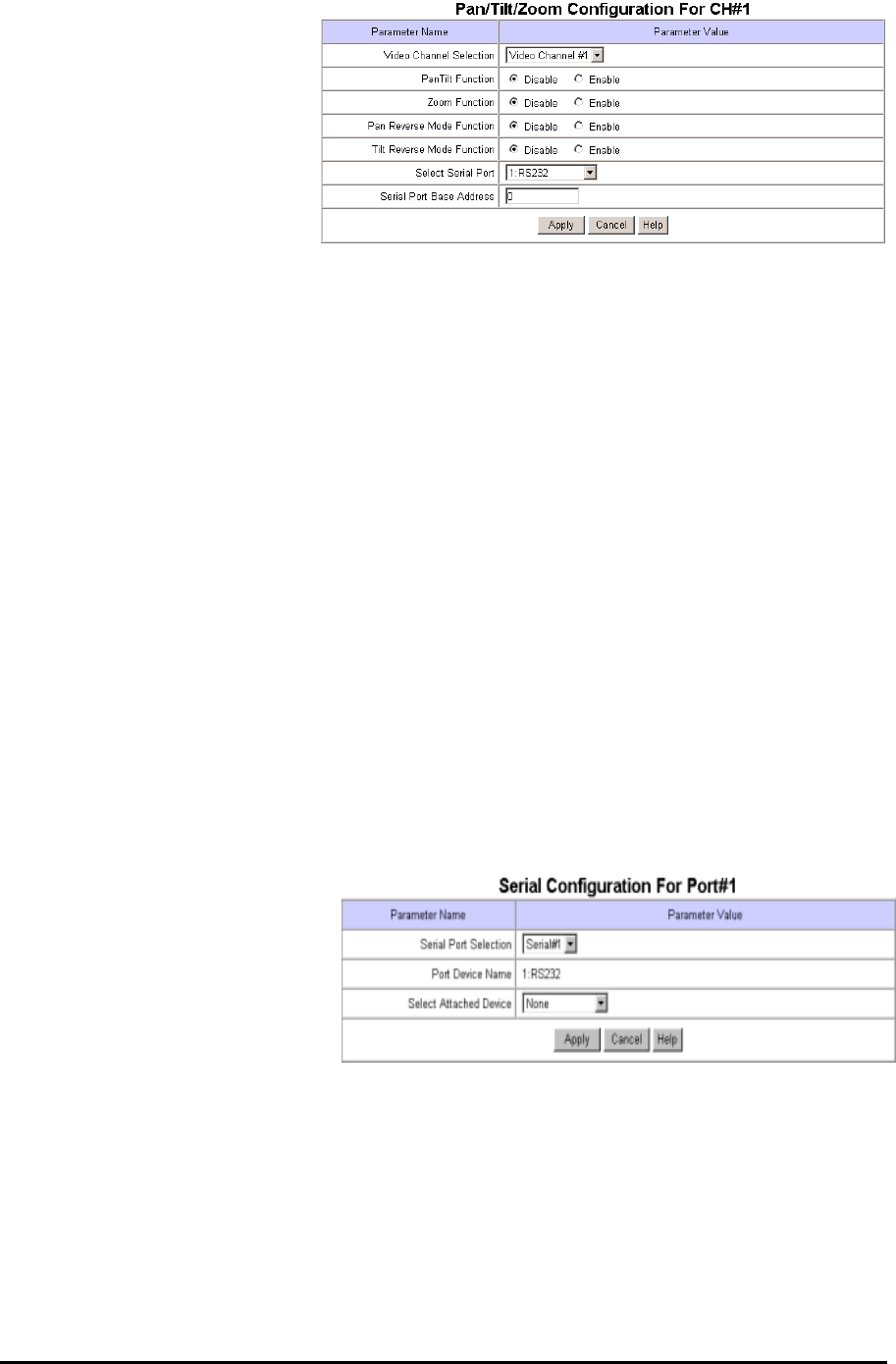
29
Webthru SWC 306 User’s Guide
are the same as seen on ‘Video
Configuration’ page.
(2) Pan Tilt Function
Administrator defines whether to
utilize pan/tilt control function or
not.
(3) Zoom Function
Administrator defines whether to utilize zoom control function or not.
(4) Pan Reverse Mode Function
This is to set command reverse direction against to right and left direction control arrows. This function is
useful when PT driver is installed upside down.
(5) Tilt Reverse Mode Function
This is to set command reverse direction against to up and down direction control arrows. This function is
useful when PT driver is installed upside down.
(6) Select Serial Port
It is to select a useable serial port as the character of pan/tilt/zoom control receiver.
It is to select a serial port between ‘Serial #1’ and ‘Serial #2’ with which a pan/tilt/zoom control receiver is
connected to Webthru. Serial #1 is RS232C interface and Serial #2 is RS422/RS485 interface.
(7) Serial Port Base Address
This menu identifies the base address for a video channel and a pan/tilt/zoom (P/T/Z) control receiver.
Webthru SWC 306 can support up to six P/T/Z devices for six separate channels when Serial #2 (RS485 Half-
Duplex) is enabled. The “Serial Port Base Address” identifies each P/T/Z device to each channel. Select a
channel to configure and change the “Serial Port Base Address” to correspond with the channel number.
10) Serial Port Configuration
This page is to select a communication
protocol among listed ones or to set
control parameters manually for each
serial port.
(1) Serial Port Selection
Administrator selects a serial port to configure. Webthru SWC 306 has two serial ports. Serial #1 is a RS232C
interface port, and Serial #2 is a RS485/RS422 interface port.
(2) Select Attached Device
Administrator selects a communication protocol that an attached external device satisfies among already listed
protocols. Samsung Techwin has listed protocols of Philips, Pelco (P and D), Sensormatic, Video Technical
(VTP 4x), LG (GAC-PT2), Sony (EVI-D3x), Surveyor (PT360 and TransitRCM), Sungjin (SJ3728R1),
Kukjae (KRS-3200), Serim (SRP-PT1), Mitsubishi (CIT7300), and Samsung Techwin (SRX100B).
Administrator may utilize any pan/tilt mechanism that satisfies already listed protocols.
30
Webthru SWC 306 User’s Guide
Audio Device
This protocol is for Webthru Audio device, which is an audio transmission device connected to Webthru.
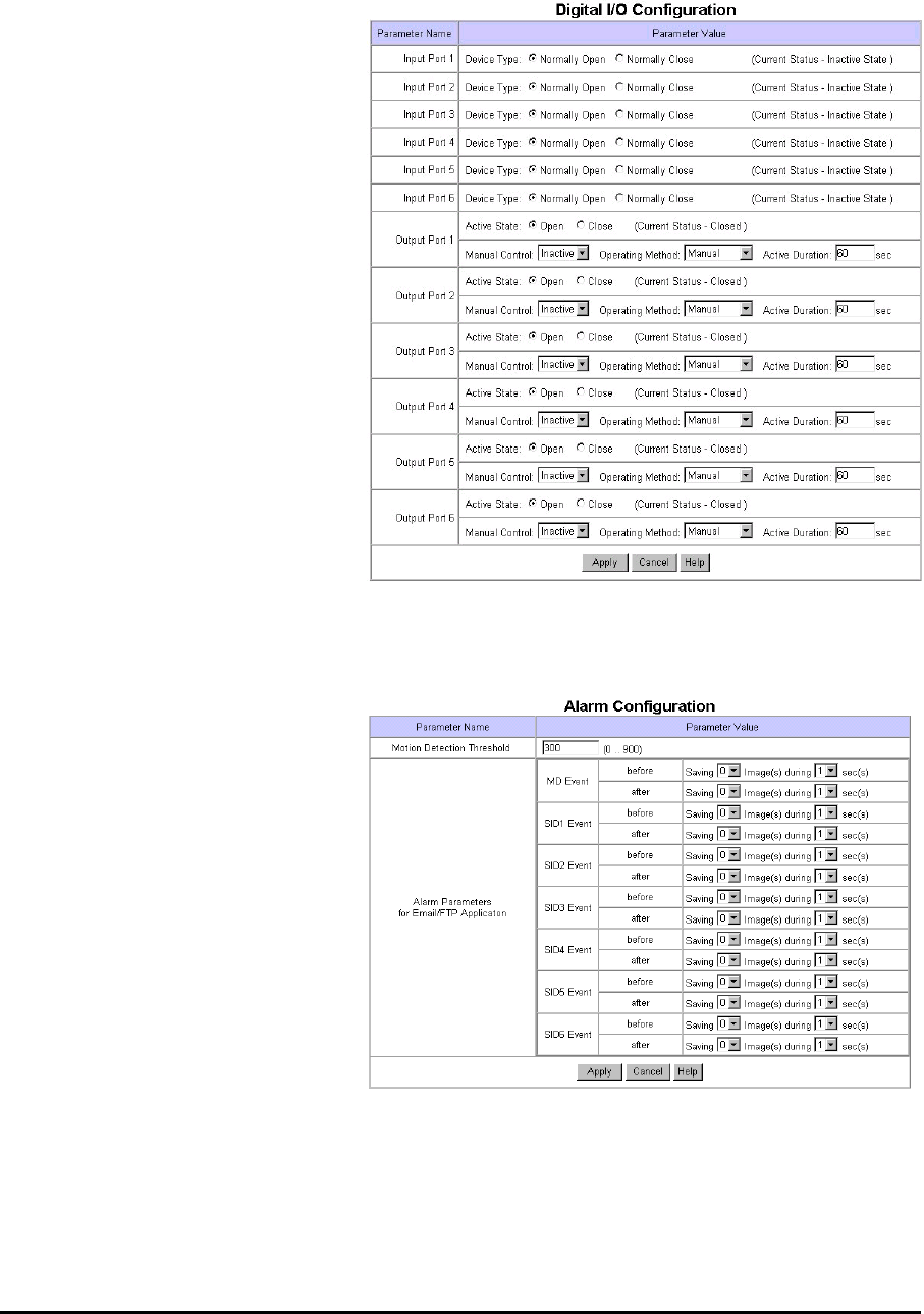
11) Digital I/O Configuration
This page is to configure digital input
state and control script. Webthru sends
e-mails or/and files when connected
external sensors detect events.
(1) Input Port 1, 2, 3, 4, 5, and 6
Administrator defines active state of 6
digital devices connected to six input
ports such as infrared sensors. If normal
open type device is connected to input
port, select ‘NO (Normally Open)’.
With normal close type device, select
‘NC (Normally Close)’.
(2) Output Port 1, 2, 3, 4, 5, and 6
Webthru shows current states of the 6
digital devices connected to 6 output
ports. In the status panel, active state or
de-active state message shows. ‘De-
Active State’ means that connected
device didn’t detect any event when ‘Apply’ button is clicked. Though this message is not updated until
‘Apply’ button is clicked again, Webthru keeps on receiving status information from the connected device.
12) Alarm Configuration
This page is to set image- recording
conditions during an event situation for
e-mail/FTP delivered images.
(1) Motion Detection Threshold
Administrator sets the threshold for
motion detection function. Threshold
‘0’ is the most sensitive state and ‘900’
is the least sensitive state.
(2) Alarm Parameters for E-mail /
FTP Application
Administrator defines the image-
recording conditions for an event, if Webthru detects events through motion detection function (MD Event) or
external devices (SID1, SID2, SID3, SID4, SID5 and SID6).
13) User Custom Configuration
This page is to customize TCP ports of data transmission and default viewer composition.

31
Webthru SWC 306 User’s Guide
(1) Web Server TCP Port
Administrator assigns a web server TCP port for user access to Webthru and data transmission from Webthru.
80th port is assigned as default value.
(2) Video Server TCP Port
Administrator assigns a video server
TCP port image transmission from
Webthru. 8080th port is assigned as
default value.
(3) Select Main Page
Administrator assigns a viewer for the
main page of Webthru. Three viewing
options are available: “Single Viewer”,
“Multi Viewer”, and “Server Push
Viewer”. “Multi Viewer” displays images through six-divided screens.
(4) Default Viewer Editing
‘Default Viewer’ is designed for users to edit easily. Editable parts are as bellows.
• Main Title: It is to change the main title displayed at the bottom of the login page.
• Logo Image Source URL: Administrator may assign the URL of any web site from which default
viewer gets a logo.
• Logo Image Link URL: Administrator may link the logo with a certain web page, such as a company or
personal homepage.
• Background Color & Foreground Color: Ground color of default viewer can be changed.
Administrator may set the color with RGB value.
14) Goto Viewer Page
This menu is to return to real time image viewer page from administration page.

32
Webthru SWC 306 User’s Guide
(Appendix 1)
Detailed Specifications of Webthru SWC 306
1. General
Hardware
CPU 32bit RISC Embedded processor
Flash memory 8MB
RAM 16MB
ROM 64KB
OS Embedded Linux
Video Channel NTSC or PAL video format are supported
6Ch. External Video Inputs
Image Resolution 720X486, 720X243, 360X243, 180X121, 90X60
Image Compression
Algorithm Wavelet
Rate 20:1 ~ 300:1
Performance
Transfer Rate Max. 120fps (With 3KB image)
Max. 30fps(NTSC) / 25 fps(PAL) (on 360X243)
Decoding Rate 2 ~ 30fps
Local Compression rate Max. 30fps/1Ch, 5fps/6Ch
Security Password Based User Authentication
IP-filtering (Secure Mode)
Image Encryption
Alarms and I/O Motion detection
Sends e-mail automatically
Sends the image files through FTP automatically
Software-controlled 6-alarm input
6 Digital Input (Coupler), 6 Digital Output (Relay)
MISC. function High quality image area setting
Image quality control (10 Levels)
Periodic sending of images through E-Mail or FTP
Gray/Progressive/Single-Shot/Channel Rotate Mode
User customized home page publishing supported by FTP
Audio supported through RS232 port
Power Supply DC 12V, 1.0A via external power supply
2. Network
Browser MS Internet Explorer V. 5.0 or higher
JAVA Applet for non PC User (MAC or Unix)
Connector Two 10 Based-T Ethernet
(Network, Loop → Stackable upto 3 boxes only with 1 IP)
Installation Assign IP address using setup program or ARP/RARP protocols
Protocols supported TCP/IP, HTTP, ARP, RARP, ICMP, DHCP, FTP, SMTP, PPP and PPPoE
S/W Upgrade Flash memory allows central remote software upgrades over network
using FTP or private “Webthru Upgrade” program

33
Webthru SWC 306 User’s Guide
Management Configuration is achieved by private setup program and Web server
built in administration page.
3. Mechanical
Dimension H x W x L = 45mm x 215mm x 252mm
Weight 1.45 kg (without power supply and accessories)
4. Compatible external devices and software
PTZ control RS-232, RS485/RS422
Sensor input 6 auxiliary inputs are supported, made of ‘Opto coupler’
Opto coupler stands with 3-5V and 10-20mA
5. Environmental
(*) This data is a target specification.
Operating Temperature 0 to 40 ℃(32 to 104 ℉)
Storage Temperature -20 to 60 ℃(-4 to 104 ℉)
Relative Humidity 10 to 75%(There should be no condensation)
Storage Humidity 10 to 95%(There should be no condensation)
Power Source D C 1 2 V ±10% (External)
Environment Indoor