Hanwha Techwin SWLQ93T WiFi Module User Manual SWL Q93T
Hanwha Techwin Co., Ltd. WiFi Module SWL Q93T
Users Manual

User manual of SWL-Q93T
1. Introduction
SWL-Q93T is a USB embedded module compliant with IEEE802.11n standard. The core
chipset is from Qualcomm, part number is AR9374X.
2. Hardware Architecture:
2.1 Main Chipset Information
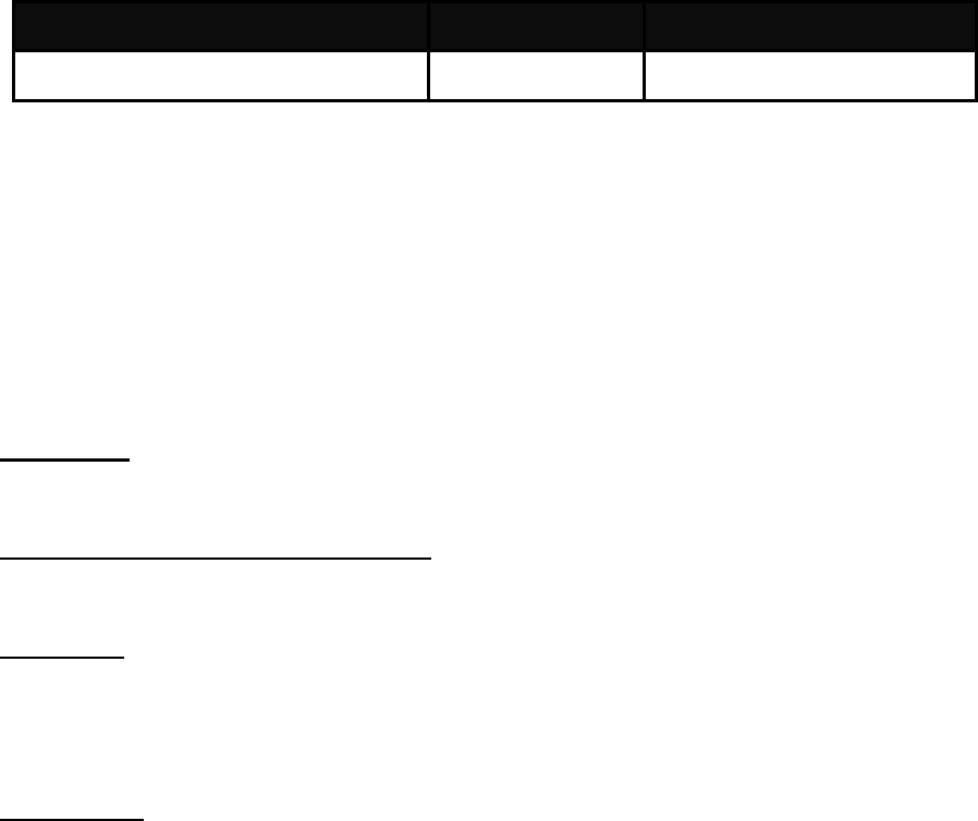
ItemVenderPartnumber
MAC/BBP/RadioTransceiver/PAQualcommAR9374X
3.3 Antennas Information
Two SMD antennas supporting both TX & RX.
4. Operational Description
SWL-Q93T is the 802.11a/b/g/n RF Module, that acts as a communication hub for users of a
wireless device to connect to a wired LAN.
MIMO type
Product type: WLAN (11b mode: 1TX, 1RX, 11g mode: 1TX, 1RX, Draft n mode: 2TX, 2RX)
Time base of the transmission frequency
For IF and RF frequency, Crystal is a clock reference.
Synthesizer
Synthesizer inside Transceiver. Internal voltage controlled oscillator (VCO) provides the desired
LO signal base on the phase-locked loop (PLL) with a relatively wide tuning range for this
application.
Transmission
Base-band Processing (BBP) IC has DSSS (BPSK/QPSK/CCK) and OFDM
(BPSK/QPSK/16QAM/64QAM) modulation function, it provides transmission data rate are 1, 2,
5.5, 11 Mbps on DSSS and 6, 12, 18, 24, 36, 48, 54 Mbps on OFDM. Digital data signal will be
converted to analog (TX IQ) signals through DAC in BBP IC, TX IQ pass through to low pass
filter. TX I/Q signal use direct conversion (zero-IF) architecture converter to generate carrier
frequency signal. Transceiver IC and internal PA magnify output power.

Receiver
Reverse direction isolation of LNA inside Transceiver IC suppresses unwanted radiation. Then
RF signal will be directly down to IF signal (RX IQ) and high frequency spurious emissions are
suppressed by LPF. At last RX IQ signal will be demodulated digital data.
Base band Processing
1. Channel selection is controlled by BBP IC to support data modulation:
- DSSS (BPSK/QPSK/CCK)
- OFDM (BPSK/QPSK/16QAM/64QAM)
Power Control Level
It uses closed-loop power control function to limit RF output power level.
Transmit/Receive Switch
EUT has Transmit/Receive Switch and Antenna switch. End user can’t select any power setting.
Channel Selection Restriction
For product available in the USA/Canada/Taiwan market, only channel 1~11 can be operated.
Selection of other channels is not possible. But product also could be available in the
Europe/Japan market, channel 1~13 can be operated under the manufacturer change the different
driver.
Data Rate Control
The operation date rate is changing during data transfer base on the optimization of driver.
Discontinue Transmitting with absence of Data or operational failure states
“The device shall automatically discontinue transmission in case of either absence of information
to transmit or operational failure. These provisions are not intended to preclude the transmission
of control or signaling information or the use of repetitive codes used by certain digital
technologies to complete frame or burst intervals. Applicants shall include in their application for
equipment authorization a description of how this requirement is met.” Data transmission is
always initiated by software, which is then passed down through the MAC, through the digital
and analog baseband, and finally to the RF chip.
Several special packets (ACKs, CTS, PSPoll, etc...) are initiated by the MAC. These are the only
ways the digital baseband portion will turn on the RF transmitter, which it then turns off at the
end of the packet. Therefore, the transmitter will be on only while one of the aforementioned
packets is being transmitted.
Product Details
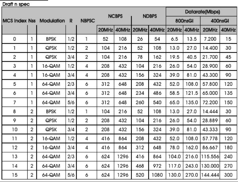
> Modulation see the below table for draft n
> Data Modulation OFDM (BPSK / QPSK / 16QAM / 64QAM)
> Frequency : 2.4GHz and 5GHz
> Data Rate (Mbps) see the below table for Draft n
> Channel Number 4 for 20MHz bandwidth ; 2 for 40MHz bandwidth

> Channel Band Width (99%) MCS8 (20MHz): 18.08 MHz ; MCS8 (40MHz): 36.48 MHz
Modulation modes
5. Notice
FCC Statement
Federal Communication Commission Interference Statement
This equipment has been tested and found to comply with the limits for a Class B digital
device, pursuant to Part 15 of the FCC Rules. These limits are designed to provide
reasonable protection against harmful interference in a residential installation. This
equipment generates, uses and can radiate radio frequency energy and, if not installed
and used in accordance with the instructions, may cause harmful interference to radio
communications. However, there is no guarantee that interference will not occur in a
particular installation. If this equipment does cause harmful interference to radio or
television reception, which can be determined by turning the equipment off and on, the
user is encouraged to try to correct the interference by one of the following measures:
● Reorient or relocate the receiving antenna.
● Increase the separation between the equipment and receiver.
● Connect the equipment into an outlet on a circuit different from that to which the
receiver is connected.
● Consult the dealer or an experienced radio/TV technician for help.
FCC Caution: Any changes or modifications not expressly approved by the party
responsible for compliance could void the user’s authority to operate this equipment.
This device complies with Part 15 of the FCC Rules. Operation is subject to the following
two conditions: (1) This device may not cause harmful interference, and (2) this device
must accept any interference received, including interference that may cause undesired
operation.
For product available in the USA/Canada market, only channel 1~11 can be operated and
these channel assignments deal with only the 2.4 GHz range.
This device and its antenna(s) must not be co-located or operation in conjunction with
any other antenna or transmitter.
This device is going to be operated in 5.15~5.25GHz frequency range, it is restricted in
indoor environment only.
IMPORTANT NOTE:
FCC Radiation Exposure Statement:
This equipment complies with FCC radiation exposure limits set forth for an uncontrolled
environment. This equipment should be installed and operated with minimum distance
20cm between the radiator & your body.
IMPORTANT NOTE:
This module is intended for OEM integrator. The OEM integrator is still responsible for
the FCC compliance requirement of the end product, which integrates this module. 20cm
minimum distance has to be able to be maintained between the antenna and the users
for the host this module is integrated into. Under such configuration, the FCC radiation
exposure limits set forth for an population/uncontrolled environment can be satisfied.
Any changes or modifications not expressly approved by the manufacturer could void
the user's authority to operate this equipment.
USERS MANUAL OF THE END PRODUCT:
In the users manual of the end product, the end user has to be informed to keep at least
20cm separation with the antenna while this end product is installed and operated. The
end user has to be informed that the FCC radio-frequency exposure guidelines for an
uncontrolled environment can be satisfied. The end user has to also be informed that
any changes or modifications not expressly approved by the manufacturer could void the
user's authority to operate this equipment. If the size of the end product is smaller than
8x10cm, then additional FCC part 15.19 statement is required to be available in the
users manual: This device complies with Part 15 of FCC rules. Operation is subject to
the following two conditions: (1) this device may not cause harmful interference and (2)
this device must accept any interference received, including interference that may cause
undesired operation.
End Product Labeling
This transmitter module is authorized only for use in device where the antenna may be
installed such that 20 cm may be maintained between the antenna and users. The final
end product must be labeled in a visible area with the following:
“Contains FCC ID: NLMSWLQ93T”.
The grantee's FCC ID can be used only when all FCC compliance requirements are
met.