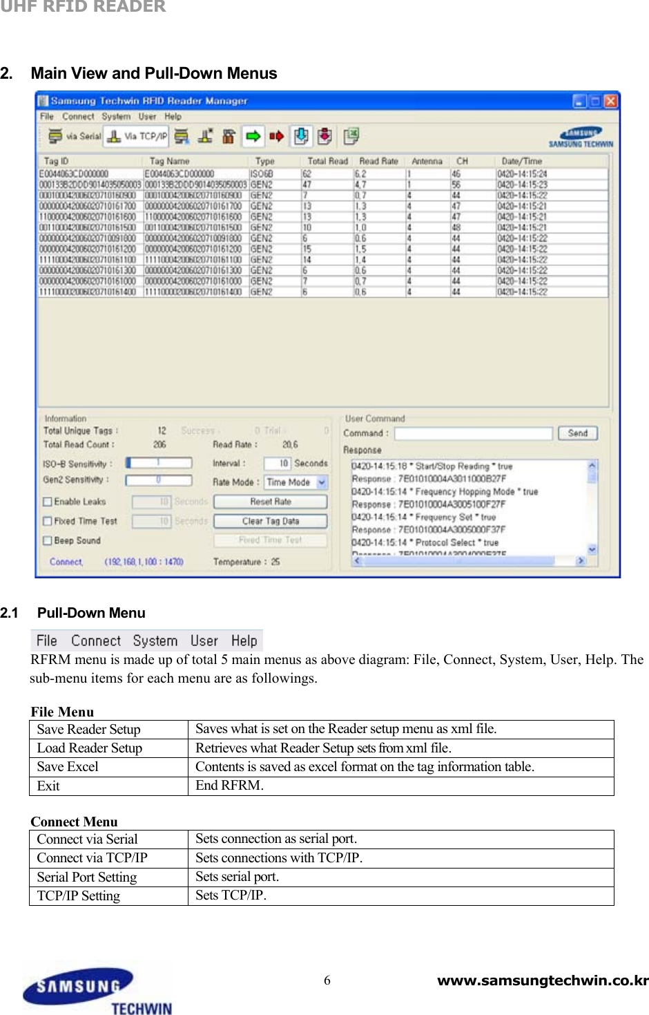
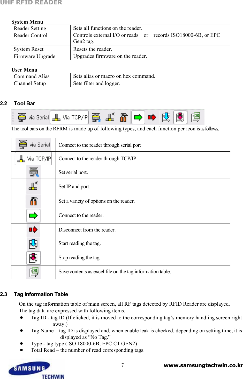
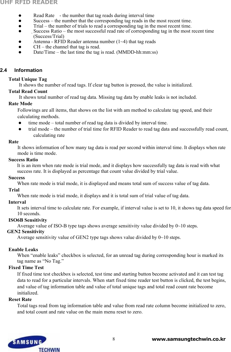
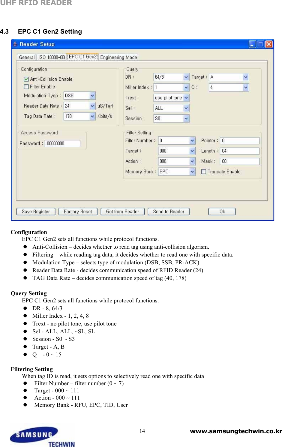
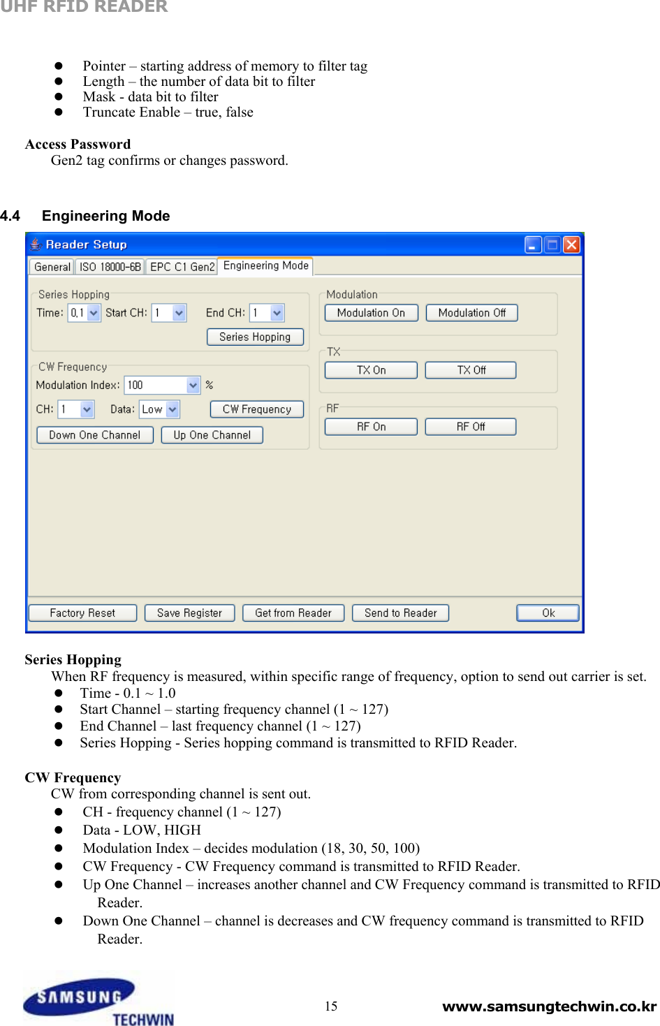
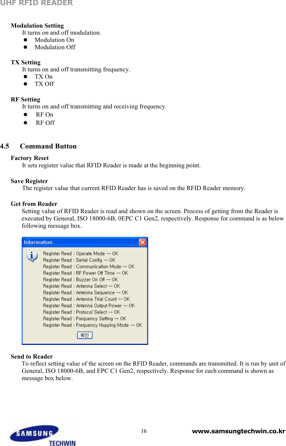
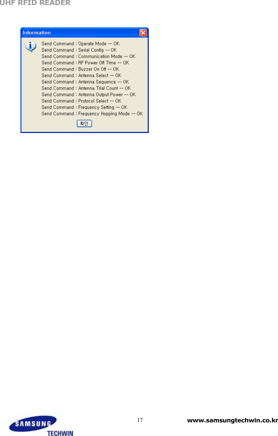
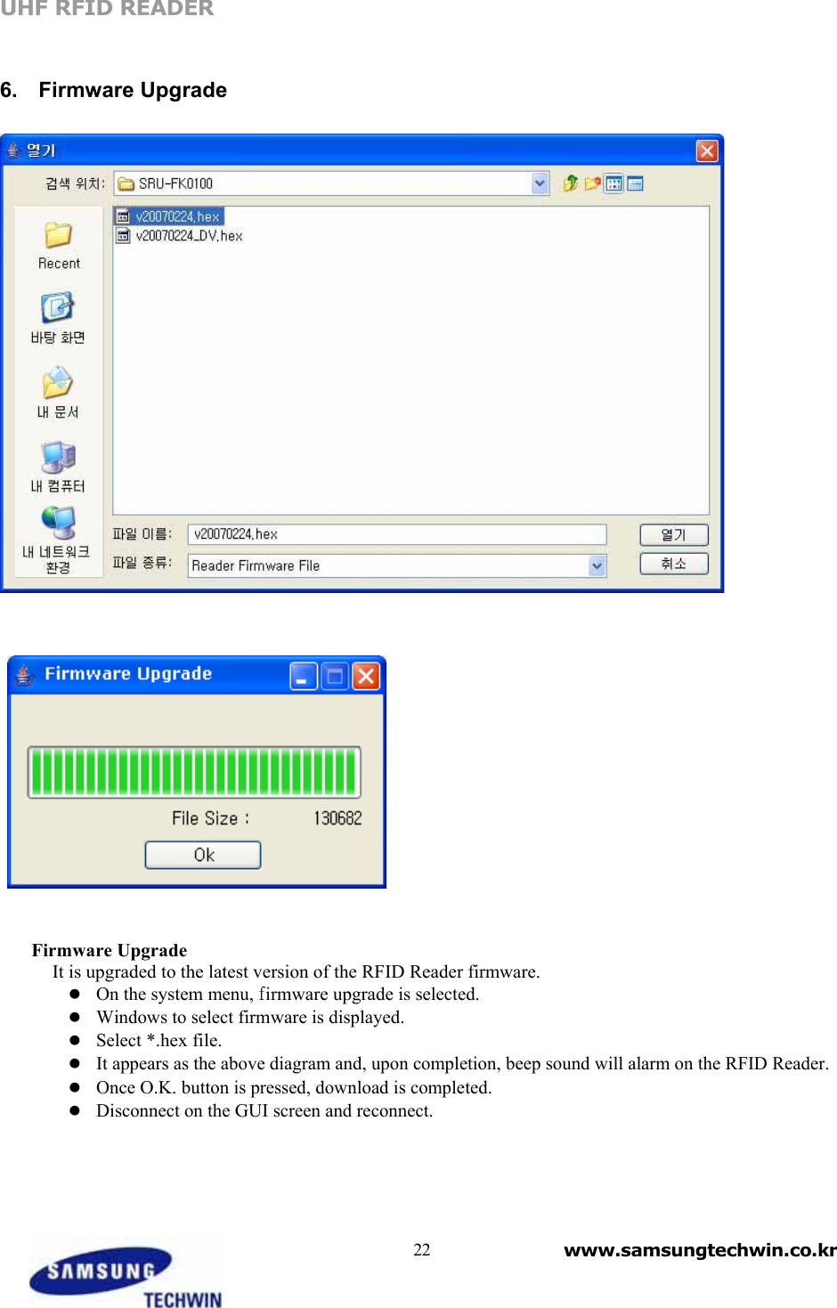
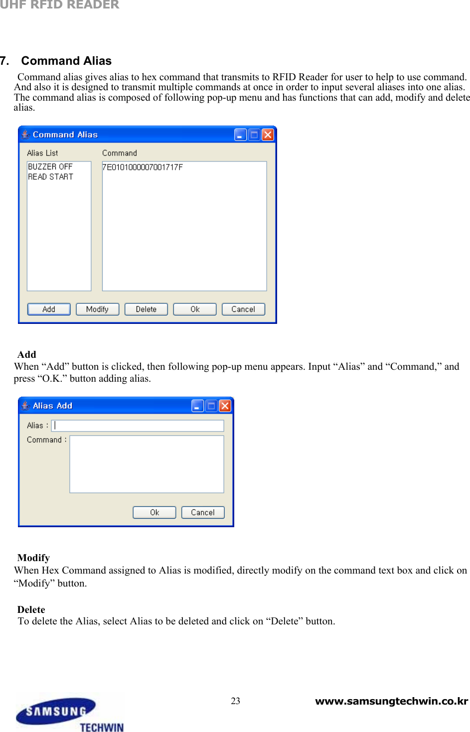
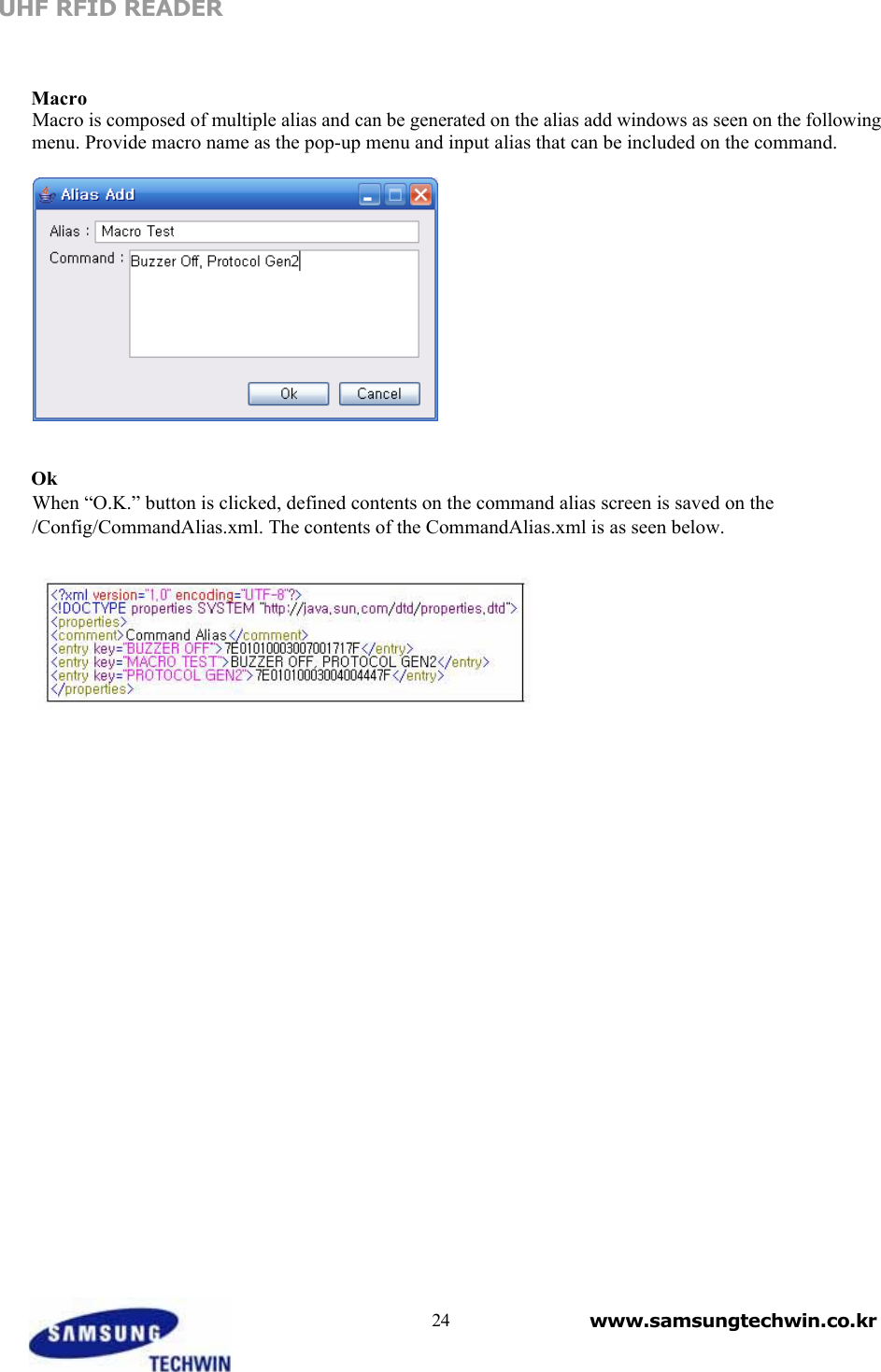
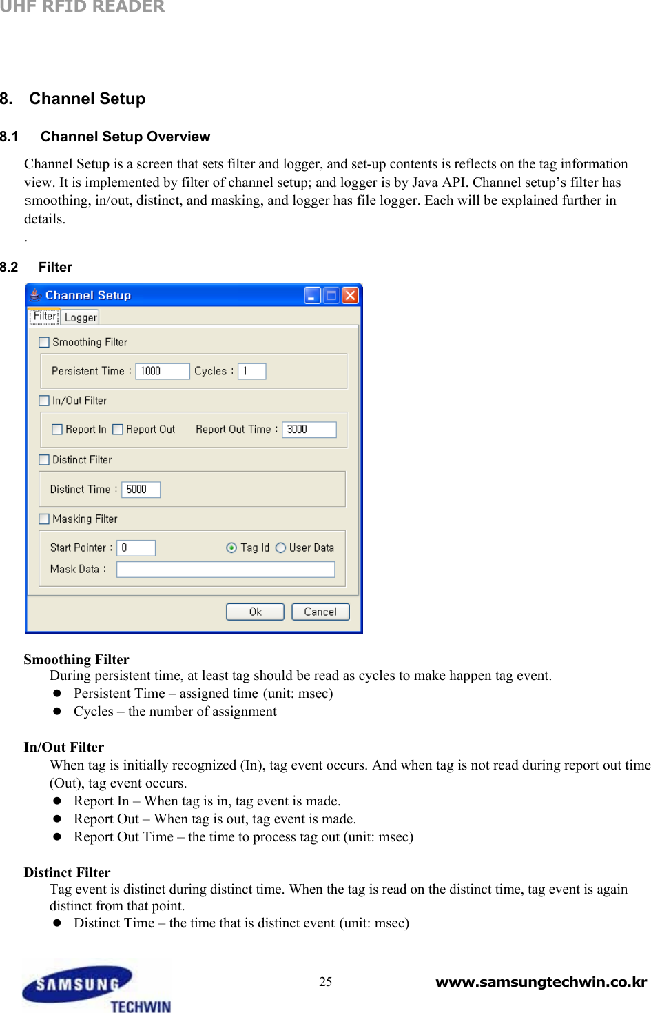
Hanwha Techwin URF-SA010 UHF RFID Fixed Reader User Manual

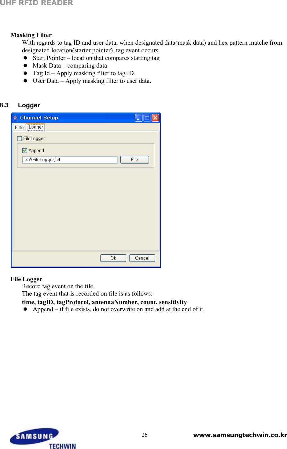
Samsung Techwin Co Ltd UHF RFID Fixed Reader

User manual

UHF RFID READER             RFID READER Manager    USER’S MANUAL                             www.samsungtechwin.co.kr
    Revision History  Date Version Description Author
UHF RFID READER     Table of Contents   1. Introduction 4 1.1 Overview 41.2 Installation 41.3 RFRM Configuration 5 2. Main View and Pull-Down Menus 6 2.1 Pull-Down Menu 62.2 Tool Bar 72.3 Tag Information Table 72.4 Information 82.5 User Command 9 3. Reader Connect Setting 10 3.1 Serial Port Setting 103.2 TCP/IP Setting 10 4. Reader Setting 11 4.1 General Setting 114.2 ISO 18000-6B Setting 134.3 EPC C1 Gen2 Setting 144.4 Test Mode 154.5 Command Button 16 5. Reader Control 18 5.1 External I/O 185.2 ISO 18000-6B Memory 195.3 EPC C1 Gen2 Memory 20 6. Firmware Upgrade 22 7.  Command Alias  23 8.  Channel Setup  258.1 Channel Setup Overview 258.2 Filter 258.3 Logger 26              3 www.samsungtechwin.co.kr
UHF RFID READER    User Manual    1.  Introduction   1.1   Overview  RFRM is a GUI application that functions on JAVA-based platform, and is developed to test and manage RFID Reader produced by Samsung Techwin.    Followings are functions that RFRM provides.    Displaying tag data    Parsing tag data  Setting/ Reset RFID Reader    Selecting tag protocol   Transmitting control command to RFID Reader   1.2   Installation  When an installing file that suits to platform is selected and executed, as seen below, an installing wizard program will be run. Then, once pressing the “Next” button with each step and selecting “installation folder,” the RFID Reader Manager will be installed.        4 www.samsungtechwin.co.kr
UHF RFID READER       1.3   RFRM Configuration   ① ②     ③                 ④ ⑤         Screen composition of RFRM is as follows:    ① Pull Down Menu – File, Connect System, User, Help. ② Toolbar – frequently used command should be transmitted to icons. ③ Tag Information Table – it displays information on the tag.  ④ Information – all options usable for simple statistical information and tag are set.   ⑤ User Command – Hex command, Alias, and Macro are transmitted, and response from reader is displayed.      5 www.samsungtechwin.co.kr
UHF RFID READER     2.  Main View and Pull-Down Menus     2.1   Pull-Down Menu   RFRM menu is made up of total 5 main menus as above diagram: File, Connect, System, User, Help. The sub-menu items for each menu are as followings.    File Menu Save Reader Setup Saves what is set on the Reader setup menu as xml file.  Load Reader Setup Retrieves what Reader Setup sets from xml file.   Save Excel Contents is saved as excel format on the tag information table.  Exit End RFRM.    Connect Menu Connect via Serial Sets connection as serial port.   Connect via TCP/IP Sets connections with TCP/IP.  Serial Port Setting Sets serial port.  TCP/IP Setting Sets TCP/IP.       6 www.samsungtechwin.co.kr
  UHF RFID READER    System Menu Reader Setting Sets all functions on the reader.   Reader Control Controls external I/O or reads  or  records ISO18000-6B, or EPC Gen2 tag.  System Reset Resets the reader.   Firmware Upgrade Upgrades firmware on the reader.  User Menu Command Alias Sets alias or macro on hex command.   Channel Setup Sets filter and logger.      2.2   Tool Bar    The tool bars on the RFRM is made up of following types, and each function per icon is as follows.     Connect to the reader through serial port   Connect to the reader through TCP/IP.   Set serial port.    Set IP and port.    Set a variety of options on the reader.    Connect to the reader.    Disconnect from the reader.    Start reading the tag.    Stop reading the tag.    Save contents as excel file on the tag information table.     2.3   Tag Information Table  On the tag information table of main screen, all RF tags detected by RFID Reader are displayed. The tag data are expressed with following items.    Tag ID - tag ID (If clicked, it is moved to the corresponding tag’s memory handling screen right         away.)   Tag Name – tag ID is displayed and, when enable leak is checked, depending on setting time, it is            displayed as “No Tag.”    Type - tag type (ISO 18000-6B, EPC C1 GEN2)   Total Read – the number of read corresponding tags.     7 www.samsungtechwin.co.kr
UHF RFID READER    Read Rate  - the number that tag reads during interval time  Success – the number that the corresponding tag reads in the most recent time.  Trial – the number of trials to read a corresponding tag in the most recent time.  Success Ratio – the most successful read rate of corresponding tag in the most recent time (Success/Trial)  Antenna - RFID Reader antenna number (1~4) that tag reads  CH – the channel that tag is read.  Date/Time – the last time the tag is read. (MMDD-hh:mm:ss)   2.4   Information  Total Unique Tag It shows the number of read tags. If clear tag button is pressed, the value is initialized.   Total Read Count It shows total number of read tag data. Missing tag data by enable leaks is not included.   Rate Mode Followings are all items, that shows on the list with am method to calculate tag speed, and their calculating methods.    time mode – total number of read tag data is divided by interval time.     trial mode – the number of trial time for RFID Reader to read tag data and successfully read count, calculating rate  Rate It shows information of how many tag data is read per second within interval time. It displays when rate mode is time mode.   Success Ratio It is an item when rate mode is trial mode, and it displays how successfully tag data is read with what success rate. It is displayed as percentage that count value divided by trial value.   Success When rate mode is trial mode, it is displayed and means total sum of success value of tag data.  Trial When rate mode is trial mode, it displays and it is total sum of trial value of tag data.  Interval It sets interval time to calculate rate. For example, if interval value is set to 10, it shows tag data speed for 10 seconds.   ISO6B Sensitivity Average value of ISO-B type tags shows average sensitivity value divided by 0~10 steps.  GEN2 Sensitivity Average sensitivity value of GEN2 type tags shows value divided by 0~10 steps.   Enable Leaks When “enable leaks” checkbox is selected, for an unread tag during corresponding hour is marked its tag name as “No Tag.”  Fixed Time Test If fixed time test checkbox is selected, test time and starting button become activated and it can test tag data to read for a particular intervals. When start fixed time reader test button is clicked, the test begins, and value of tag information table and value of total unique tags and total read count rate become initialized.  Reset Rate Total tags read from tag information table and value from read rate column become initialized to zero, and total count and rate value on the main menu reset to zero.      8 www.samsungtechwin.co.kr
UHF RFID READER     Clear Tag Data Delete tag information table.  Beep Sound If “Beep Sound” checkbox is selected, beep alarms when tag data is read.  Temperature It displays temperatures on the reader.   2.5   User Command  Command Right after command is input as Hex String, Alias, or Macro on the input control, the command is transmitted to the connected RFID Reader when the “Send” button is pressed.   Response Response packet from the RFID Reader regarding the received command is displayed.                                                9 www.samsungtechwin.co.kr
UHF RFID READER     3.  Reader Connect Setting   3.1   Serial Port Setting The serial port is set as COM port, or baud rate.       Port – COM port is selected on the host.  Baud Rate – sets communication speed.  Data Bits – sets data bit.  Parity Bit – sets parity bit.  Stop Bit – sets stop bit.     3.2   TCP/IP Setting IP and port are set on the reader.       Address –IP Address is set on the Reader.  Port – Port is set on the Reader.           10 www.samsungtechwin.co.kr
UHF RFID READER     4.  Reader Setting   4.1   General Setting    OP Mode Setting It decides work mode of RFID Reader.     Transfer - Polled, Continuous    Read - continuous, polled_command, polled_external_input    RF - On, Off    Trial Count – 0 ~ 255    Transfer Time – 100 ~ 1000 msec (100 msec interval)    External I/O Port – it chooses from external I/O Port 1,2, or 3.    RF Power off  Time - 100 ~ 1000 msec (100 msec interval)  Antenna Setting It sets to use antenna 1~4 and their options.    Sequence – sets using order on the antenna  Trial – sets antenna trial count  Power – antenna output power is set.  Available Antenna – searches antenna that is connected with RFID reader.    Serial Setting It sets serial communication speed on the reader.      Baud Rate – sets communication speed of the reader.     11 www.samsungtechwin.co.kr
UHF RFID READER       Multi-drop Address – sets multi-drop address.   Serial Mode Setting Sets frequency channels to use   From – sets “Start” channel   To – sets “End” channel   Hopping Mode – select whether frequency hopping will be at random basis or in a series basis within the selected frequency band (Random, Series).  Protocol Setting Sets protocol (ISO 18000-6B, EPC C1, EPC C1 Gen2).  Buzzer It turns on and off the buzzer of RFID Reader.    Communication The communication method for RFID Reader is set.   Communication Mode – RS232, Ethernet                                          12 www.samsungtechwin.co.kr
UHF RFID READER     4.2   ISO 18000-6B Setting    Configuration ISO18000-6B : sets all functions while protocol works.   Anti-Collision – using anti-collision algorism, it decides whether to read tag.  Filter Enable – decides whether to read selectively read one with specific data when reading tag data   EPC 1.19 – decides whether to apply EPC1.19 protocol  ID Length – decides the length of tag ID (64, 96)  Modulation Index – decides modulation (18, 30, 50, 100)  Reader Data Rate – decides RFID Reader’s communication speed (40)  TAG Data Rate – decides tag’s communication speed (40, 160)       Filtering Setting When tag ID is being read, particular data is selected and it sets options to read.    Filter Number – filter number (0 ~ 7)   (Un) Selection - Select_EQ, select_GT, select_LT, Unselect_EQ, Unselect_GT, Unselect_LT   Address - tag memory address   Mask - it decides bites to compare when tag’s memory data and data are compared.   Data - data to compare              13 www.samsungtechwin.co.kr
UHF RFID READER     4.3   EPC C1 Gen2 Setting    Configuration EPC C1 Gen2 sets all functions while protocol functions.    Anti-Collision – decides whether to read tag using anti-collision algorism.  Filtering – while reading tag data, it decides whether to read one with specific data.  Modulation Type – selects type of modulation (DSB, SSB, PR-ACK)  Reader Data Rate - decides communication speed of RFID Reader (24)  TAG Data Rate – decides communication speed of tag (40, 178)  Query Setting EPC C1 Gen2 sets all functions while protocol functions.    DR - 8, 64/3  Miller Index - 1, 2, 4, 8  Trext - no pilot tone, use pilot tone  Sel - ALL, ALL, ~SL, SL  Session - S0 ~ S3  Target - A, B  Q  - 0 ~ 15  Filtering Setting When tag ID is read, it sets options to selectively read one with specific data  Filter Number – filter number (0 ~ 7)  Target - 000 ~ 111  Action - 000 ~ 111  Memory Bank - RFU, EPC, TID, User      14 www.samsungtechwin.co.kr
UHF RFID READER      Pointer – starting address of memory to filter tag   Length – the number of data bit to filter   Mask - data bit to filter   Truncate Enable – true, false   Access Password Gen2 tag confirms or changes password.    4.4   Engineering Mode    Series Hopping When RF frequency is measured, within specific range of frequency, option to send out carrier is set.   Time - 0.1 ~ 1.0  Start Channel – starting frequency channel (1 ~ 127)  End Channel – last frequency channel (1 ~ 127)  Series Hopping - Series hopping command is transmitted to RFID Reader.    CW Frequency CW from corresponding channel is sent out.     CH - frequency channel (1 ~ 127)   Data - LOW, HIGH   Modulation Index – decides modulation (18, 30, 50, 100)   CW Frequency - CW Frequency command is transmitted to RFID Reader.   Up One Channel – increases another channel and CW Frequency command is transmitted to RFID Reader.   Down One Channel – channel is decreases and CW frequency command is transmitted to RFID Reader.      15 www.samsungtechwin.co.kr
UHF RFID READER    Modulation Setting It turns on and off modulation.    Modulation On  Modulation Off    TX Setting It turns on and off transmitting frequency.    TX On  TX Off  RF Setting It turns on and off transmitting and receiving frequency.   RF On   RF Off   4.5   Command Button  Factory Reset It sets register value that RFID Reader is made at the beginning point.    Save Register The register value that current RFID Reader has is saved on the RFID Reader memory.  Get from Reader Setting value of RFID Reader is read and shown on the screen. Process of getting from the Reader is executed by General, ISO 18000-6B, 0EPC C1 Gen2, respectively. Response for command is as below following message box.      Send to Reader To reflect setting value of the screen on the RFID Reader, commands are transmitted. It is run by unit of  General, ISO 18000-6B, and EPC C1 Gen2, respectively. Response for each command is shown as message box below.         16 www.samsungtechwin.co.kr
UHF RFID READER                                                   17 www.samsungtechwin.co.kr
UHF RFID READER    5.  Reader Control   5.1   External I/O    Write to External I/O – outputs on the exterior output port  Data - 1  Byte Data Read from External I/O – it reads status of exterior output port and displays it.  Get Product Revision - RFID Reader’s version and serial number are transmitted and are displayed.                            18 www.samsungtechwin.co.kr
UHF RFID READER     5.2   ISO 18000-6B Memory    Memory Handling - Read Reads data of the corresponding memory address  ID - tag ID  Address - tag memory address (0x00 ~ 0xDF)  Length – the number of bites to be read from the corresponding memory address (below 128 byte)  Memory Handling - Write Writes corresponding data on the corresponding memory address.   ID - tag ID  Address - tag memory address (0x00 ~ 0xDF)  Length – number of bites to be recorded (below 128 byte)  Data - data to be recorded (below 255 byte)    Memory Handling- Lock Lock on the corresponding memory address.    ID - tag ID   Address - tag memory address (0x00 ~ 0xDF)   Length – the number of bites to lock from the corresponding memory address              19 www.samsungtechwin.co.kr
UHF RFID READER     5.3   EPC C1 Gen2 Memory    Memory Handling - Read It reads data value of the corresponding memory address.    ID - tag ID  Memory Bank - RFU, EPC, TID, User  WORD Pointer - tag memory address (automatically operated to EVB)  WORD Count – the number of data word that is to be read from corresponding memory address  Memory Handling - Write Corresponding data value is written on the corresponding memory address.   TAG ID  - tag ID   Memory Bank - RFU, EPC, TID, User   WORD Pointer - tag memory address (automatically operated to EVB)   WORD Count - the number of data word to be read from the corresponding memory address   WORD Data – the data to record (more than 1 word)  Memory Handling – Lock Lock corresponding memory address.    ID - tag ID  Password - Lock 4 bites password  Lock Mask – If the Lock Mask button is clicked, following diagram will pop up. Check each item               and press “O.K.” button. Then, automatically Lock Mask value of 3 bites is calculated.             20 www.samsungtechwin.co.kr
UHF RFID READER      Memory Handling - Kill Kills tag  ID - tag ID  Password - Kill password 4 bites                                        21 www.samsungtechwin.co.kr
UHF RFID READER    6.  Firmware Upgrade           Firmware Upgrade It is upgraded to the latest version of the RFID Reader firmware.  On the system menu, firmware upgrade is selected.  Windows to select firmware is displayed.   Select *.hex file.  It appears as the above diagram and, upon completion, beep sound will alarm on the RFID Reader.  Once O.K. button is pressed, download is completed.  Disconnect on the GUI screen and reconnect.       22 www.samsungtechwin.co.kr
UHF RFID READER     7.  Command Alias Command alias gives alias to hex command that transmits to RFID Reader for user to help to use command. And also it is designed to transmit multiple commands at once in order to input several aliases into one alias. The command alias is composed of following pop-up menu and has functions that can add, modify and delete alias.      Add When “Add” button is clicked, then following pop-up menu appears. Input “Alias” and “Command,” and press “O.K.” button adding alias.       Modify When Hex Command assigned to Alias is modified, directly modify on the command text box and click on “Modify” button.   Delete To delete the Alias, select Alias to be deleted and click on “Delete” button.         23 www.samsungtechwin.co.kr
UHF RFID READER     Macro Macro is composed of multiple alias and can be generated on the alias add windows as seen on the following menu. Provide macro name as the pop-up menu and input alias that can be included on the command.      Ok When “O.K.” button is clicked, defined contents on the command alias screen is saved on the /Config/CommandAlias.xml. The contents of the CommandAlias.xml is as seen below.                                         24 www.samsungtechwin.co.kr
UHF RFID READER      8.  Channel Setup  8.1   Channel Setup Overview  Channel Setup is a screen that sets filter and logger, and set-up contents is reflects on the tag information view. It is implemented by filter of channel setup; and logger is by Java API. Channel setup’s filter has smoothing, in/out, distinct, and masking, and logger has file logger. Each will be explained further in details. .  8.2   Filter    Smoothing Filter During persistent time, at least tag should be read as cycles to make happen tag event.   Persistent Time – assigned time (unit: msec)  Cycles – the number of assignment  In/Out Filter When tag is initially recognized (In), tag event occurs. And when tag is not read during report out time (Out), tag event occurs.   Report In – When tag is in, tag event is made.  Report Out – When tag is out, tag event is made.   Report Out Time – the time to process tag out (unit: msec)  Distinct Filter Tag event is distinct during distinct time. When the tag is read on the distinct time, tag event is again distinct from that point.    Distinct Time – the time that is distinct event (unit: msec)    25 www.samsungtechwin.co.kr
UHF RFID READER     Masking Filter With regards to tag ID and user data, when designated data(mask data) and hex pattern matche from designated location(starter pointer), tag event occurs.   Start Pointer – location that compares starting tag   Mask Data – comparing data  Tag Id – Apply masking filter to tag ID.  User Data – Apply masking filter to user data.    8.3   Logger    File Logger Record tag event on the file.  The tag event that is recorded on file is as follows:   time, tagID, tagProtocol, antennaNumber, count, sensitivity  Append – if file exists, do not overwrite on and add at the end of it.                      26 www.samsungtechwin.co.kr
 Federal Communication Commission Interference Statement  This equipment has been tested and found to comply with the limits for a Class B digital device, pursuant to Part 15 of the FCC Rules. These limits are designed to provide reasonable protection against harmful interference in a residential installation. This equipment generates, uses and can radiate radio frequency energy and, if not installed and used in accordance with the instructions, may cause harmful interference to radio communications. However, there is no guarantee that interference will not occur in a particular installation. If this equipment does cause harmful interference to radio or television reception, which can be determined by turning the equipment off and on, the user is encouraged to try to correct the interference by one of the following measures: • Reorient or relocate the receiving antenna. • Increase the separation between the equipment and receiver. • Connect the equipment into an outlet on a circuit different from that to which the receiver is con-nected. • Consult the dealer or an experienced radio/TV technician for help.  FCC Caution: To assure continued compliance, (example - use only shielded interface cables when connecting to computer or peripheral devices). Any changes or modifications not expressly approved by the party responsible for compliance could void the user’s authority to operate this equipment.This device complies with Part 15 of the FCC Rules. Operation is subject to the following two conditions: (1) This device may not cause harmful interference, and (2) this device must accept any interference received, including interference that may cause undesired operation  IMPORTANT NOTE: FCC RF Radiation Exposure Statement: This equipment complies with FCC RF radiation exposure limits set forth for an uncontrolled environment. This equipment should be installed and operated with a minimum distance of 20 centimeters between the radiator and your body.This transmitter must not be co-located or operating in conjunction with any other antenna or transmitter.
IMPORTANT Safety Instruction:   1) Read these instructions. 2) Keep these instructions. 3) Heed all warnings. 4) Follow all instructions.   5) Do not use this equipment near water. 6) Do not using near any heat sources such as radiators, heat resisters, stove, or other equipment that produce heat. 7) Internal Lithium coin batteries type:   - Rechargeable coin battery(BT2) SANYO ENERGY, ML 2430     - RTC(Real Time Clock) coin battery(BT1) FDK Energy Co., Ltd., CR 2032   * This device will only be installed professionally *Antenna information - Antenna type : PANNEL Antenna - Antenna Gain : 5.19dBi - RF cable length : 5m

Navigation menu