Harbor Freight 1102 Users Manual
1102 to the manual 678c0139-879d-4710-a8fd-ec9b30a0ff2b
2015-01-25
: Harbor-Freight Harbor-Freight-1102-Users-Manual-210139 harbor-freight-1102-users-manual-210139 harbor-freight pdf
Open the PDF directly: View PDF ![]() .
.
Page Count: 10
REUSABLE / REFILLABLE
AEROSOL SPRAY CAN
1102
SET UP AND OPERATING INSTRUCTIONS
Distributed exclusively by Harbor Freight Tools®.
3491 Mission Oaks Blvd., Camarillo, CA 93011
Visit our website at: http://www.harborfreight.com
Read this material before using this product.
Failure to do so can result in serious injury.
SAVE THIS MANUAL.
Copyright© 2008 by Harbor Freight Tools®. All rights reserved. No portion of this manual or any artwork
contained herein may be reproduced in any shape or form without the express written consent of
Harbor Freight Tools. Diagrams within this manual may not be drawn proportionally. Due to continuing
improvements, actual product may differ slightly from the product described herein. Tools required for
assembly and service may not be included.
For technical questions or replacement parts, please call 1-800-444-3353.
SKU 1102 For technical questions, please call 1-800-444-3353. Page 2
SAVE THIS MANUAL
Keep this manual for the safety warn-
ings and precautions, assembly, operat-
ing, inspection, maintenance and cleaning
procedures. Write the product’s serial
number in the back of the manual near the
assembly diagram (or month and year of
purchase if product has no number). Keep
this manual and the receipt in a safe and
dry place for future reference.
Safety Alert Symbol and Signal
Words
In this manual, on the labeling,
and all other information provid-
ed with this product:
This is the safety alert
symbol. It is used to alert
you to potential personal
injury hazards. Obey all
safety messages that
follow this symbol to avoid
possible injury or death.
DANGER indicates
a hazardous
situation which, if not
avoided, will result in death or
serious injury.
WARNING
indicates a
hazardous situation which, if
not avoided, could result in
death or serious injury.
CAUTION, used
with the safety
alert symbol, indicates a
hazardous situation which, if
not avoided, could result in
minor or moderate injury.
NOTICE is used to
address practices
not related to personal injury.
CAUTION, without
the safety alert
symbol, is used to address
practices not related to
personal injury.
IMPORTANT SAFETY
INSTRUCTIONS
INSTRUCTIONS PERTAINING
TO A RISK OF FIRE,
ELECTRIC SHOCK, OR
INJURY TO PERSONS
WARNING – When using tools, basic pre-
cautions should always be followed,
including the following:
General
a. To reduce the risks of electric
shock, re, and injury to persons,
read all the instructions before us-
ing the tool.
WARNING marking concerning Risk
of Eye Injury. Wear ANSI-approved
eye protection.
WARNING marking concerning Risk
of Hearing Loss. Wear hearing
protection.
WARNING marking concerning Risk
of Respiratory Injury. Wear NIOSH-
approved dust mask/respirator.
WARNING marking concerning Risk
of Explosion.
Symbol Denitions
Symbol Property or statement

SKU 1102 For technical questions, please call 1-800-444-3353. Page 3
Work area
a. Keep the work area clean and well
lighted. Cluttered benches and dark
areas increase the risks of electric
shock, re, and injury to persons.
b. Do not operate the tool in explo-
sive atmospheres, such as in the
presence of ammable liquids,
gases, or dust. The tool is able to
create sparks resulting in the ignition
of the dust or fumes.
c. Keep bystanders, children, and
visitors away while operating the
tool. Distractions are able to result in
the loss of control of the tool.
Personal safety
a. Stay alert. Watch what you are do-
ing and use common sense when
operating the tool. Do not use the
tool while tired or under the inu-
ence of drugs, alcohol, or medica-
tion. A moment of inattention while
operating the tool increases the risk
of injury to persons.
b. Dress properly. Do not wear loose
clothing or jewelry. Contain long
hair. Keep hair, clothing, and
gloves away from moving parts.
Loose clothes, jewelry, or long hair
increases the risk of injury to persons
as a result of being caught in moving
parts.
c. Do not overreach. Keep proper
footing and balance at all times.
Proper footing and balance enables
better control of the tool in unexpect-
ed situations.
d. Use safety equipment. A
dust mask, non-skid safety
shoes and a hard hat must
be used for the applicable
conditions. Wear heavy-duty work
gloves during use.
e. Always wear eye protec-
tion. Wear ANSI-ap-
proved safety goggles.
Tool use and care
a. Do not force the tool. Use the
correct tool for the application. The
correct tool will do the job better and
safer at the rate for which the tool is
designed.
b. Disconnect the tool from the air
source before making any adjust-
ments, changing accessories, or
storing the tool. Such preventive
safety measures reduce the risk of
starting the tool unintentionally. Turn
off and detach the air supply, safely
discharge any residual air pressure,
and release the throttle and/or turn
the switch to its off position before
leaving the work area.
c. Store idle tool out of reach of chil-
dren and other untrained persons.
A tool is dangerous in the hands of
untrained users.
d. Maintain tool with care. A properly
maintained tool is easier to control.
e. Check for misalignment or bind-
ing of moving parts, breakage of
parts, and any other condition that
affects the tool’s operation. If dam-
aged, replace Spray Can. There is a
risk of bursting if the tool is damaged.

SKU 1102 For technical questions, please call 1-800-444-3353. Page 4
Air source
a. Never connect to an air
source that is capable of
exceeding 90 PSI. Over
pressurizing the tool may
cause bursting, abnormal operation,
breakage of the tool or serious injury
to persons. Use only clean, dry,
regulated compressed air at the rated
pressure or within the rated pressure
range as marked on the tool. Always
verify prior to using the tool that the
air source has been adjusted to the
rated air pressure or within the rated
air-pressure range.
b. Never use oxygen, carbon dioxide,
combustible gases or any bottled
gas as an air source for the tool.
Such gases are capable of explosion
and serious injury to persons.
SAVE THESE
INSTRUCTIONS.
Specic Safety Instructions
1. The warnings and precautions dis-
cussed in this manual cannot cover
all possible conditions and situations
that may occur. It must be under-
stood by the operator that common
sense and caution are factors which
cannot be built into this product, but
must be supplied by the operator.
2. Do not use with bottled gases.
3. Always keep Sealing Gasket (3) in
place.
4. Check all local laws regarding use.
5. Do not puncture or incinerate Spray
Can.
6. Do not use with corrosive products.
7. A tire chuck (not included) must be
attached to the air supply hose in
order to pressurize Spray Can.
8. Do not expose to heat or store at
temperature above 120° F.
9. Obey the manual for the hand pump
and the compressor used to power
this tool.
10. Flush the system with pressurized
clean water after use with liquids
other than water.
11. Do not overll the Spray Can. It
holds 16 uid ounces (max. lled
liquid should not exceed 8 uid ounc-
es.)
12. Read warnings of uids and applica-
tions used with Spray Can. Adhere to
all safety warnings concerning han-
dling of applications.
13. DO NOT spray up wind.
14. Before storing, discharge contents,
ush with clean water, and wash
and dry exterior. Then store in a safe
place out of reach of children.
SAVE THESE
INSTRUCTIONS.
SKU 1102 For technical questions, please call 1-800-444-3353. Page 5
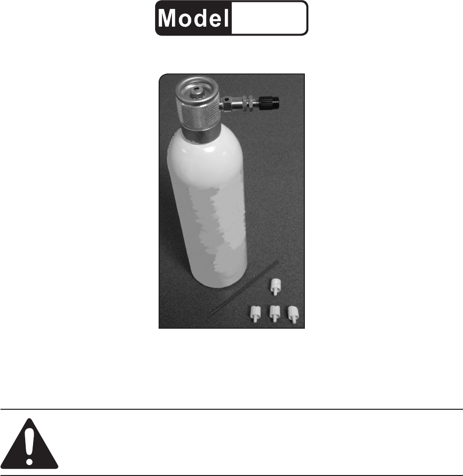
Specications
Max. Air Pressure 90 PSI
Air Inlet Schrader (Bicycle) Valve
Capacity 16 uid ounces
Spray Buttons (4)
Coarse Spray (Green)
Medium Spray (Black)
Fine Spray (Blue)
Jet (No color; equipped
with opening for jet spray
extension)
INITIAL TOOL SET UP/
ASSEMBLY
Read the ENTIRE IMPORTANT
SAFETY INFORMATION
section at the beginning of this
manual including all text under
subheadings therein before set
up or use of this product.
Note: For additional information regarding
the parts listed in the following pages,
refer to the Assembly Diagram near
the end of this manual.
Unpacking
When unpacking, make sure that
the item is intact and undamaged. If any
parts are missing or broken, please call
Harbor Freight Tools at the number shown
throughout the manual as soon as pos-
sible.
• This air tool may be shipped with a
protective plug covering the air inlet.
Remove this plug before set up.
Air Supply
TO PREVENT
EXPLOSION:
Use only clean, dry, regulated,
compressed air to power this
tool. Do not use oxygen,
carbon dioxide, combustible
gases, or any other bottled
gas as a power source for this
tool.
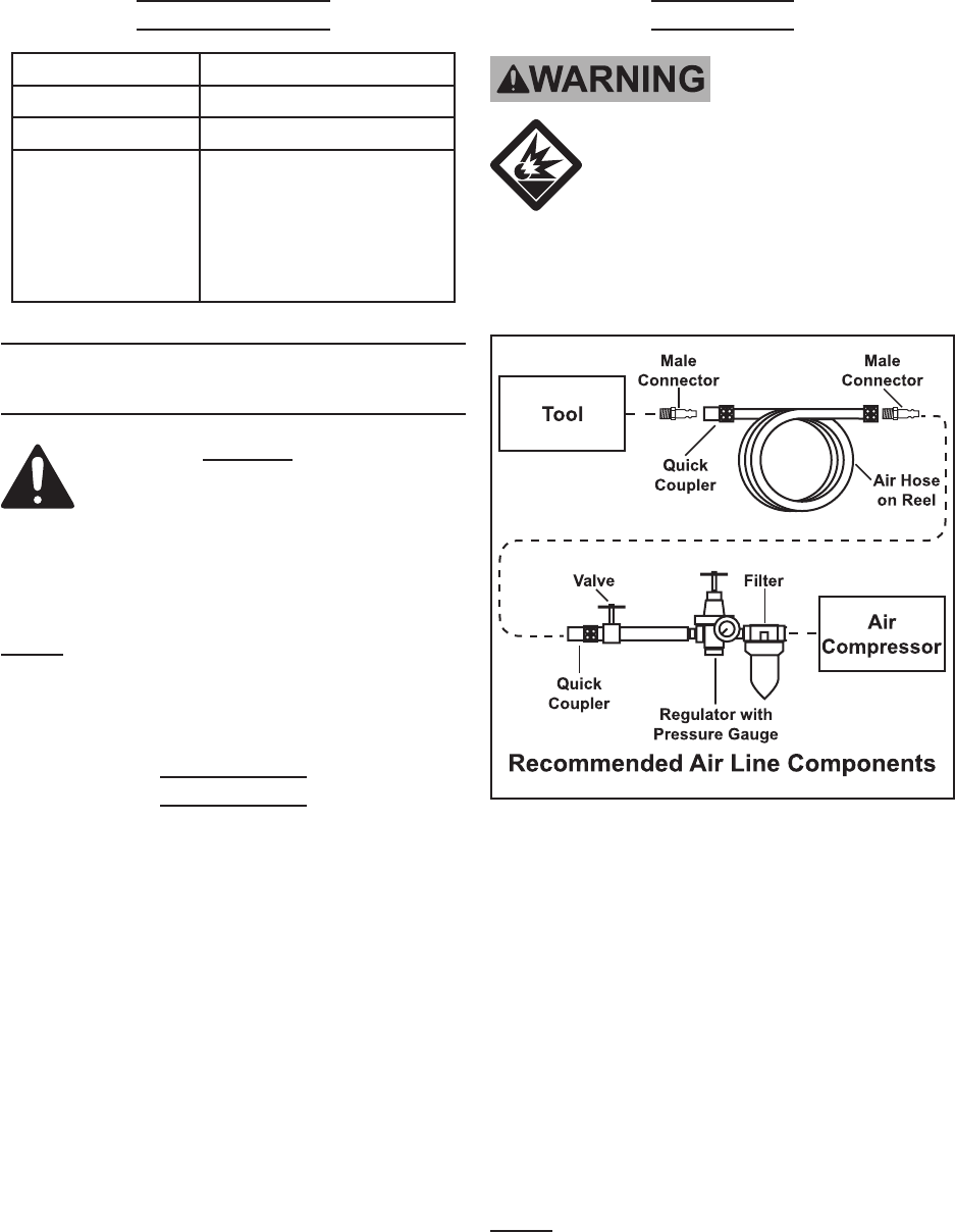
1. Incorporate an in-line shut-off valve,
regulator with pressure gauge, and
lter for best service, as shown in the
diagram above. An in-line shutoff
valve is an important safety device
because it controls the air supply
in the event of an air hose rupture
or other emergencies.
2. Attach a tire chuck to one end of the
air supply hose and the other end
of the hose to the air supply (neither
one is supplied.)
Note: Air ow, and therefore tool perfor-
mance, can be hindered by under-
sized air supply components.
SKU 1102 For technical questions, please call 1-800-444-3353. Page 6
3. Close the in-line safety valve be-
tween the compressor and the tool.
4. Turn on the air compressor according
to the manufacturer’s directions and
allow it to build up pressure until it
cycles off.
5. Adjust the air compressor’s output
regulator so that the air output is
enough to properly charge the tool,
but the output will not exceed the
tool’s maximum air pressure require-
ment at any time. Adjust the pres-
sure gradually, while checking the air
output gauge to set the right pressure
range.
6. Inspect the air connections for leaks.
Repair any leaks found.
Note: Residual air pressure should not be
present after the tool is disconnected
from the air supply. However, it is a
good safety measure to attempt to
discharge the tool in a safe fashion
after disconnecting to ensure that the
tool is disconnected and unpowered.
OPERATING INSTRUCTIONS
Read the ENTIRE IMPORTANT
SAFETY INFORMATION
section at the beginning of this
manual including all text under
subheadings therein before set
up or use of this product.
Inspect tool before use, looking
for damaged, loose, and
missing parts. If any problems
are found, do not use tool until
repaired or replaced.
Tool Set Up
TO PREVENT
SERIOUS INJURY:
Do not adjust or tamper with
any control or component in a
way not specically explained
within this manual. Improper
adjustment can result in tool
failure or other serious
hazards.
General Operating Instructions
1. Twist off the Head Unit (1) from the
Tank (4) and inspect the Sealing Gas-
ket (3). Replace if damaged.
2. If used with liquids, ll ONLY halfway
with the liquid to be sprayed (max. 8
uid ounces.)
3. Replace the Head Unit and twist shut.
4. Unscrew and remove Valve Cap (10),
place the other end of Cap into valve
stem and check that valve core (not
shown) is tight.
5. Attach Air Chuck to Valve Stem (2).
6. Pressurize Spray Can to 90 PSI max.
WARNING! Be careful of discharge
during tting.
7. Fit selected Spray Button onto top of
Head Unit:
a.) Coarse Spray - Green Button
(6). Use on heavy viscous liquids
such as oil and wax
b.) Medium Spray - Black Button
(7). Use on medium viscous liquids
such as paints, window cleaner.

SKU 1102 For technical questions, please call 1-800-444-3353. Page 7
c.) Fine Spray - Blue Button (8).
Use on this viscous liquids such as
insecticides, water, or nal coating
cellulose.
d.) Jet Spray - No Color (5). Used
Jet Extension (4) for hard to reach
spots. Attach the Jet Extension to Jet
Spray before inserting it into Spray
Can.
8. Shake can to mix liquid contents.
Then hold upright and press on Spray
Button.
USER-MAINTENANCE
INSTRUCTIONS
Procedures not specically
explained in this manual
must be performed only by a
qualied technician.
TO PREVENT
SERIOUS INJURY
FROM ACCIDENTAL
OPERATION: Detach the air
supply, safely discharge any
residual air pressure in the
tool before performing any
inspection, maintenance, or
cleaning procedures.
TO PREVENT SERIOUS
INJURY FROM TOOL
FAILURE: Do not use
damaged equipment. If
abnormal noise, vibration,
or leaking air occurs, have
the problem corrected before
further use.
Cleaning, Maintenance, and
Lubrication
Note: These procedures are in addition to
the regular checks and maintenance
explained as part of the regular op-
eration of the air-operated tool.
1. When nished, discharge air pres-
sure by pressing on the stem of the
valve core with a narrow screwdriver
tip. Twist of the Head Unit (1) and
empty contents of Tank (4) in a safe
area.
2. Fill the Spray Can with fty percent
fresh water and reattach the Head
Unit.
3. Pressurize the Spray Can. Aim the
Button into a bucket containing some
water and depress the button to
discharge the Tank contents, ushing
the system.
NOTE: This step can be omitted if the
Spray Can was used with fresh-water
applications or as an air duster.
4. Clean external surface of the tool with
a clean, dry cloth. Then store indoors
and out of reach of children.
SKU 1102 For technical questions, please call 1-800-444-3353. Page 8
Troubleshooting
Problem Possible Causes Likely Solutions
Spray only “jets”. 1. Can is overlled.
2. Product is too thin.
3. Incorrect air pressure.
4. Button has been blocked.
5. Broken Spray Button.
1. Make sure can is not lled over 50 percent
with liquid.
2. Add product with correct thickness.
3. Make sure air pressure is between 50 and 90
PSI.
4. Clean or replace clogged button.
5. Pry out Spray Button and replace with new
one. Do not insert anything through supply
tube attached to the valve body.
Air bubbles
appear in sprayed
material.
1. Incorrect air pressure.
2. Using incorrect Spray Button.
1. Make sure air pressure is between 50 and 90
PSI.
2. Switch Spray Buttons and apply ner coating
before coating dries.
Severe air
leakage.
1. Cross-threaded Valve Body.
2. Damaged valve or housing.
3. Dirty, worn or damaged
Sealing Gasket.
4. Loose or bad valve core.
1. Back off and reattach.
2. Replace damaged components.
3. Replace Sealing Gasket.
4. Tighten/replace valve core.
Follow all safety precautions whenever diagnosing or servicing the
tool. Disconnect air supply before service.
SKU 1102 For technical questions, please call 1-800-444-3353. Page 9
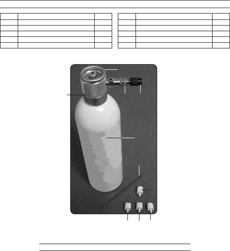
PARTS LIST AND ASSEMBLY DIAGRAM
Part Description Q’ty
1 Head Unit 1
2 Valve Stem 1
3 Sealing Gasket (not shown) 1
4 Tank 1
5 Jet Extension 1
Part Description Q’ty
6 Jet Spray Button 1
7 Coarse Spay Button (Green) 1
8 Medium Spray Button (Black) 1
9 Fine Spray Button (Blue) 1
10 Valve Cap 1
PLEASE READ THE FOLLOWING CAREFULLY
THE MANUFACTURER AND/OR DISTRIBUTOR HAS PROVIDED THE PARTS LIST AND ASSEMBLY
DIAGRAM IN THIS MANUAL AS A REFERENCE TOOL ONLY. NEITHER THE MANUFACTURER OR
DISTRIBUTOR MAKES ANY REPRESENTATION OR WARRANTY OF ANY KIND TO THE BUYER THAT
HE OR SHE IS QUALIFIED TO MAKE ANY REPAIRS TO THE PRODUCT, OR THAT HE OR SHE IS
QUALIFIED TO REPLACE ANY PARTS OF THE PRODUCT. IN FACT, THE MANUFACTURER AND/
OR DISTRIBUTOR EXPRESSLY STATES THAT ALL REPAIRS AND PARTS REPLACEMENTS SHOULD
BE UNDERTAKEN BY CERTIFIED AND LICENSED TECHNICIANS, AND NOT BY THE BUYER. THE
BUYER ASSUMES ALL RISK AND LIABILITY ARISING OUT OF HIS OR HER REPAIRS TO THE
ORIGINAL PRODUCT OR REPLACEMENT PARTS THERETO, OR ARISING OUT OF HIS OR HER
INSTALLATION OF REPLACEMENT PARTS THERETO.
4
1
10
5
6
7 8 9
32

SKU 1102 For technical questions, please call 1-800-444-3353. Page 10
Record Product’s Serial Number Here:
Note: If product has no serial number, record month and year of purchase instead.
Note: Some parts are listed and shown for illustration purposes only, and are not avail-
able individually as replacement parts.
90 Day Warranty
Harbor Freight Tools Co. makes every effort to assure that its products meet high quality
and durability standards, and warrants to the original purchaser that this product is free
from defects in materials and workmanship for the period of 90 days from the date of
purchase. This warranty does not apply to damage due directly or indirectly, to misuse,
abuse, negligence or accidents, repairs or alterations outside our facilities, criminal
activity, improper installation, normal wear and tear, or to lack of maintenance. We
shall in no event be liable for death, injuries to persons or property, or for incidental,
contingent, special or consequential damages arising from the use of our product.
Some states do not allow the exclusion or limitation of incidental or consequential
damages, so the above limitation of exclusion may not apply to you. THIS WARRANTY
IS EXPRESSLY IN LIEU OF ALL OTHER WARRANTIES, EXPRESS OR IMPLIED,
INCLUDING THE WARRANTIES OF MERCHANTABILITY AND FITNESS.
To take advantage of this warranty, the product or part must be returned to us with
transportation charges prepaid. Proof of purchase date and an explanation of the
complaint must accompany the merchandise. If our inspection veries the defect, we
will either repair or replace the product at our election or we may elect to refund the
purchase price if we cannot readily and quickly provide you with a replacement. We will
return repaired products at our expense, but if we determine there is no defect, or that
the defect resulted from causes not within the scope of our warranty, then you must
bear the cost of returning the product.
This warranty gives you specic legal rights and you may also have other rights which
vary from state to state.
3491 Mission Oaks Blvd. • PO Box 6009 • Camarillo, CA 93011 • (800) 444-3353
