Harbor Freight 95955 Owner S Manual
2014-07-05
: Harbor-Freight Harbor-Freight-95955-Owner-S-Manual harbor-freight-95955-owner-s-manual harbor-freight pdf
Open the PDF directly: View PDF ![]() .
.
Page Count: 16

ELECTRIC PORTABLE
PIPE THREADER
Model
95955
OPERATION INSTRUCTIONS
Diagrams within this manual may not be drawn proportionally.
Due to continuing improvements, actual product may differ slightly from the product described herein.
Distributed exclusively by Harbor Freight Tools®.
3491 Mission Oaks Blvd., Camarillo, CA 93011
Visit our website at: http://www.harborfreight.com
Read this material before using this product.
Failure to do so can result in serious injury.
SAVE THIS MANUAL.
Copyright© 2007 by Harbor Freight Tools®. All rights reserved. No portion of this
manual or any artwork contained herein may be reproduced in any shape or form
without the express written consent of Harbor Freight Tools.
For technical questions or replacement parts, please call 1-800-444-3353.

Page 2SKU 95955 For technical questions, please call 1-800-444-3353.
SPECIFICATIONS
Motor 120 VAC / 60 Hz / 1606 W (start-up)/ 12 A
20 RPM @ Drive/No Load
Accessible Motor Brushes
Die Sizes 1/2”, 3/4”, 1” & 1-1/4” dies marked with NPT and sizing (included)
Power Cord 6.2’ Long, 2-Prong Plug
Save This Manual
You will need this manual for the safety warnings and precautions, assembly, operat-
ing, inspection, maintenance, cleaning procedures, parts list and assembly diagram. Keep
your invoice with this manual. Write the invoice number on the inside of the front cover.
Write the product’s serial number in the back of the manual near the assembly diagram, or
write month and year of purchase if product has no number. Keep this manual and invoice
in a safe and dry place for future reference.
GENERAL SAFETY RULES
WARNING!
READ AND UNDERSTAND ALL INSTRUCTIONS
Failure to follow all instructions listed below may result in
electric shock, fire, and/or serious injury.
SAVE THESE INSTRUCTIONS
WORK AREA
Keep your work area clean and well lit. 1. Cluttered benches and dark areas invite
accidents.
Do not operate power tools in explosive atmospheres, such as in the pres-2.
ence of flammable liquids, gases, or dust. Power tools create sparks which can
ignite the dust or fumes.
Keep bystanders and children away while operating a power tool. 3. Distractions
can cause you to lose control. Protect others in the work area from debris such as
chips and sparks. Provide barriers or shields as needed.
ELECTRICAL SAFETY
Grounded tools must be plugged into a properly installed and grounded outlet 1.
in accordance with local codes and ordinances. Never remove the grounding

Page 3SKU 95955 For technical questions, please call 1-800-444-3353.
prong or modify the plug in any way. Do not use any adapter plugs. Check with a
qualified electrician if you are in doubt as to whether the outlet is properly grounded.
If the tools should electrically malfunction or break down, grounding provides a low
resistance path to carry electricity away from the user.
Double insulated tools are equipped with a polarized plug (one blade is 2.
wider than the other). This plug will fit in a polarized outlet only one way. If the
plug does not fit fully in the outlet, reverse the plug. If it still does not fit, contact a
qualified electrician to install a polarized outlet. Do not change the plug in any way.
Double insulation eliminates the need for the three wire grounded power cord
and grounded power supply system.
Avoid body contact with grounded surfaces such as pipes, radiators, ranges, 3.
and refrigerators. There is an increased risk of electric shock if your body is
grounded.
Do not expose power tools to rain or wet conditions. 4. Water entering a power
tool will increase the risk of electric shock.
Do not abuse the Power Cord. 5. Never use the Power Cord to carry the tools or pull
the Plug from an outlet. Keep the Power Cord away from heat, oil, sharp edges,
or moving parts. Replace damaged Power Cords immediately. Damaged Power
Cords increase the risk of electric shock.
When operating a power tool outside, use an outdoor extension cord marked 6.
“W-A” or “W”. These extension cords are rated for outdoor use, and reduce the
risk of electric shock.
PERSONAL SAFETY
Stay alert. 1. Watch what you are doing and use common sense when operating a
power tool. Do not use a power tool while tired or under the influence of drugs,
alcohol, or medication. A moment of inattention while operating power tools can
result in serious personal injury.
Dress properly. 2. Do not wear loose clothing or jewelry. Contain long hair. Keep
your hair, clothing, and gloves away from moving parts. Loose clothes, jewelry, or
long hair can be caught in moving parts.
Avoid accidental starting. 3. Be sure the Power Switch is off before plugging in.
Carrying power tools with your finger on the Power Switch can cause accidents.
Remove adjusting keys or wrenches before turning the power tool on. 4. A
wrench or a key that is left attached to a rotating part of the power tool can result
in personal injury.
Do not overreach. Keep proper footing and balance at all times. 5. Proper footing
and balance enables better control of the power tool in unexpected situations.

Page 4SKU 95955 For technical questions, please call 1-800-444-3353.
Use safety equipment. Always wear eye protection. 6. Dust mask, nonskid safety
shoes, hard hat, or hearing protection must be used for appropriate conditions. Al-
ways wear ANSI-approved safety goggles and a dust mask/respirator when using
or performing maintenance on this tool.
TOOL USE AND CARE
Do not use the power tool if the Power Switch does not turn it on or off. 1. Any
tool that cannot be controlled with the Power Switch is dangerous and must be
replaced.
Disconnect the Power Cord Plug from the power source before making any 2.
adjustments, changing accessories, or storing the tool. Such preventive safety
measures reduce the risk of starting the tool accidentally. Always unplug the tool
from the electrical outlet before performing any inspection, maintenance, or
cleaning procedures.
Store idle tools out of reach of children and untrained persons. 3. Tools are
dangerous in the hands of untrained users.
Maintain tools with care. 4. Do not use a damaged tool. Tag damaged tools “Do
not use” until repaired.
Check for misalignment or binding of moving parts, breakage of parts, and any 5.
other condition that can affect the tool’s operation. If damaged, have the tool
serviced before using. Many accidents are caused by poorly maintained tools.
SERVICE
Tool service must be performed only by qualified repair personnel. 1. Service or
maintenance performed by unqualified personnel could result in a risk of injury.
When servicing a tool, use only identical replacement parts. Follow instruc-2.
tions in the “Inspection, Maintenance, And Cleaning” section of this manual.
Use of unauthorized parts or failure to follow maintenance instructions can create
a risk of electric shock or injury.
SPECIFIC SAFETY RULES
Maintain labels and nameplates on the tool. 1. These carry important information.
If unreadable or missing, contact Harbor Freight Tools for a replacement.
Wear ANSI-approved safety impact eye goggles, heavy-duty work gloves 2.
and dust mask/respirator when using the Pipe Threader. Using personal safety
devices reduces the risk of injury.
Maintain a safe working environment. 3. Make sure there is adequate surrounding
workspace.
Page 5SKU 95955 For technical questions, please call 1-800-444-3353.
Always keep the extension cord away from the moving parts on the tool.4.
Never leave the tool unattended when it is plugged into an electrical outlet. 5.
Turn off the tool, and unplug it from the electrical outlet before leaving area.
Always secure the pipe being threaded with the Pipe Clamp assembly (54, 6.
55, 56).
People with pacemakers should consult their physician(s) before using this 7.
product. Electromagnetic fields in close proximity to a heart pacemaker could cause
interference to, or failure of, the pacemaker. In addition, people with pacemakers
should adhere to the following:
• Avoid operating power tools alone.
• Don’t use a power tool with the power switch locked on.
• If powered via a power cord, be certain that the tool is properly grounded. A ground
fault interrupt (GFCI) system is also a good precaution. This inexpensive device is
a good safety measure because it prevents a sustained electrical shock.
• Properly maintain and inspect all tools before use to avoid electrical shock.
Direction switch must be fully engaged to the “in” or “out” position before 8.
use.
Never disable safety button. 9. The safety button can help prevent accidental start-
ing.
WARNING: Some dust created by power sanding, sawing, grinding, drilling, 10.
and other construction activities, contains chemicals known [to the State of
California] to cause cancer, birth defects or other reproductive harm. Some
examples of these chemicals are:
Lead from lead-based paints
Crystalline silica from bricks and cement or other masonry products
Arsenic and chromium from chemically treated lumber
Your risk from these exposures varies, depending on how often you do this type of
work. To reduce your exposure to these chemicals: work in a well ventilated area,
and work with approved safety equipment, such as those dust masks that are spe-
cially designed to filter out microscopic particles. (California Health & Safety Code
§ 25249.5, et seq.)
Page 6SKU 95955 For technical questions, please call 1-800-444-3353.
GROUNDING
WARNING!
Improperly connecting the grounding wire can result in the risk of electric shock.
Check with a qualified electrician if you are in doubt as to whether the outlet is
properly grounded. Do not modify the power cord plug provided with the tool.
Never remove the grounding prong from the plug. Do not use the tool if the
power cord or plug is damaged. If damaged, have it repaired by a service facil-
ity before use. If the plug will not fit the outlet, have a proper outlet installed by
a qualified electrician.
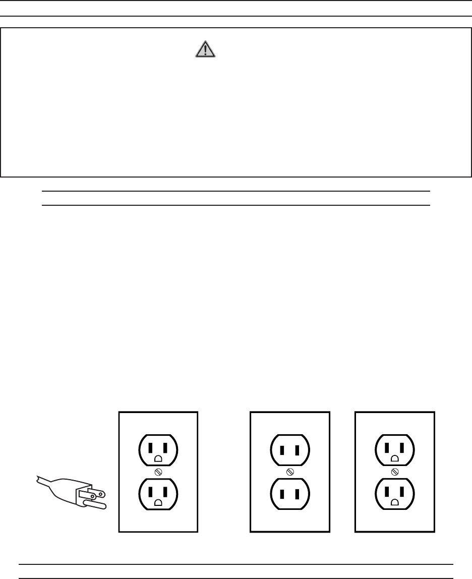
GROUNDED TOOLS: TOOLS WITH THREE PRONG PLUGS
Tools marked with “Grounding Required” have a three wire cord and three prong 1.
grounding plug. The plug must be connected to a properly grounded outlet. If the
tool should electrically malfunction or break down, grounding provides a low resis-
tance path to carry electricity away from the user, reducing the risk of electric shock.
(See 3-Prong Plug and Outlet.)
The grounding prong in the plug is connected through the green wire inside the 2.
cord to the grounding system in the tool. The green wire in the cord must be the
only wire connected to the tool’s grounding system and must never be attached to
an electrically “live” terminal. (See 3-Prong Plug and Outlet.)
Your tool must be plugged into an appropriate outlet, properly installed and grounded 3.
in accordance with all codes and ordinances. The plug and outlet should look like
those in the following illustration. (See 3-Prong Plug and Outlet.)
3-Prong Plug and Outlet Outlets for 2-Prong Plug
DOUBLE INSULATED TOOLS: TOOLS WITH TWO PRONG PLUGS
Tools marked “Double Insulated” do not require grounding. They have a special 1.
double insulation system which satisfies OSHA requirements and complies with
the applicable standards of Underwriters Laboratories, Inc., the Canadian Standard
Association, and the National Electrical Code. (See Outlets for 2-Prong Plug.)

Page 7SKU 95955 For technical questions, please call 1-800-444-3353.
Double insulated tools can be used in either of the 120 volt outlets shown in the 2.
preceding illustration. (See Outlets for 2-Prong Plug.)
EXTENSION CORDS
Grounded1. tools require a three wire extension cord. Double Insulated tools can
use either a two or three wire extension cord.
As the distance from the supply outlet increases, you must use a heavier gauge 2.
extension cord. Using extension cords with inadequately sized wire causes a seri-
ous drop in voltage, resulting in loss of power and possible tool damage.
(See Table A.)
The smaller the gauge number of the wire, the greater the capacity of the cord. For 3.
example, a 14 gauge cord can carry a higher current than a 16 gauge cord.
(See Table A.)
When using more than one extension cord to make up the total length, make sure 4.
each cord contains at least the minimum wire size required. (See Table A.)
If you are using one extension cord for more than one tool, add the nameplate5. am-
peres and use the sum to determine the required minimum cord size.
(See Table A.)
If you are using an extension cord outdoors, make sure it is marked with the suffix 6.
“W-A” (“W” in Canada) to indicate it is acceptable for outdoor use.
Make sure your extension cord is properly wired and in good electrical condition. 7.
Always replace a damaged extension cord or have it repaired by a qualified electri-
cian before using it.
Protect your extension cords from sharp objects, excessive heat, and damp or wet 8.
areas.

Page 8SKU 95955 For technical questions, please call 1-800-444-3353.
RECOMMENDED MINIMUM WIRE GAUGE FOR EXTENSION CORDS*
(120 OR 240 VOLT)
NAMEPLATE
AMPERES
(at full load)
EXTENSION CORD LENGTH
25 Feet 50 Feet 75 Feet 100 Feet 150 Feet
0 – 2.0 18 18 18 18 16
2.1 – 3.4 18 18 18 16 14
3.5 – 5.0 18 18 16 14 12
5.1 – 7.0 18 16 14 12 12
7.1 – 12.0 18 14 12 10 -
12.1 – 16.0 14 12 10 - -
16.1 – 20.0 12 10 - - -
TABLE A * Based on limiting the line voltage drop to five volts at 150% of the rated amperes.
SYMBOLOGY
Double Insulated
Canadian Standards Association
Underwriters Laboratories, Inc.
V~ Volts Alternating Current
AAmperes
n0 xxxx/min. No Load Revolutions per Minute (RPM)
UNPACKING
When unpacking, check to make sure that all parts shown on Assembly Diagram
are included. If any parts are missing or broken, please call Harbor Freight Tools at the
number shown on the cover of this manual as soon as possible.
Page 9SKU 95955 For technical questions, please call 1-800-444-3353.
OPERATION
Note: For additional information regarding the parts listed in the following pages, refer to
the Assembly Diagram near the end of this manual.
CAUTION!1. Always make sure the Pipe Threader is disconnected from the electri-
cal outlet prior to assembling the tool, changing accessories, or performing service
on the product.
Wear ANSI-approved safety impact eye goggles, heavy-duty work gloves, and 2.
dust mask/respirator when using the Pipe Threader. Using personal safety
devices reduces the risk of injury.
Select the appropriate Die (58, 59, 60, 61) to be used. 3. NOTE: Dies are intended
for use on standard schedule 40 and schedule 80 steel pipe.
Insert the Die into the Die Holder (25) of the Pipe Threader. The Die fits into the 4.
Die Holder only one way. Make sure the Die is secured in place before proceeding.
The Die is pressure fitted so once it is inserted properly, it may require light tapping
with a wooden mallet (sold separately) to remove the Die.
Make sure the accessory Oil Can (57) is filled with Thread Cutting Oil (not included) 5.
and ready to be used during the threading operation.
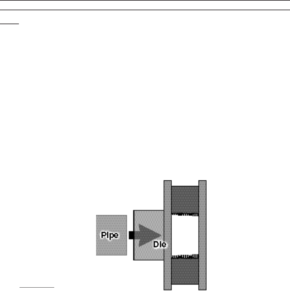
Insert the pipe into the rear of the Die. Make sure the inside diameter of the Die 6.
matches the outside diameter of the pipe.
(See Figure F.)
FIGURE F

Page 10SKU 95955 For technical questions, please call 1-800-444-3353.
FIGURE G
PIPE CLAMP (56)
PIPE
CAUTION!7. Always use the Pipe Clamp assembly (54, 55, 56) to secure and sup-
port the pipe during the threading operation. Screw Rod (55) into Clamp (56) and
secure with Nut (54). Make sure the Pipe Clamp assembly is securely clamping the
pipe and that the pipe is supported while the threads are being cut. (See Figure
G.) Be certain that the pipe has enough clearance to proceed.
Make sure the pipe end and threads of the Die are sufficiently oiled at all times. Oth-8.
erwise, the life of the Die Blades will be shortened and the threads will be rough.
Located on the Safety Handle (41) is a Rotation Direction Switch (40) which deter-9.
mines the direction of the threading operation. Flip the Rotating Direction Switch
to the right position for a clockwise rotation. (See Figure H.)
11. Connect the Power Cord Plug (38) into the nearest 110 volt grounded electrical
outlet.
Safety Handle (41)
Trigger (39)
Handle (35)
Rotation Direction
Switch (40)
FIGURE H
While holding the Handle (35), press the Trigger (39) in and squeeze the Safety 12.
Handle (41). Pipe Threader will not engage until the Safety handle is firmly
grasped. Apply pressure until the Die engages the pipe, cutting two to three threads.
(See Figure H.)

Page 11SKU 95955 For technical questions, please call 1-800-444-3353.
From this point, the Die will automatically be drawn over the pipe and a standard 13.
taper thread will be cut.
To ensure a good, clean standard taper thread, stop the Pipe Threader every few 14.
turns, reverse, oil the pipe, and re-cut the thread.
Stop threading when the end of the Die is flush with the end of the pipe. At this 15.
point, the correct thread length has been reached to produce the proper joint. To
continue beyond this point would make a straight or running thread.
To stop threading, release the Power Switch to stop the Pipe Threader. Allow the 16.
Pipe Threader to completely stop. Then turn the Rotating Direction Switch to the
left position for a counterclockwise rotation of the Die. Pull in and up on the Power
Switch to turn on the Pipe Threader and disengage the Die from the pipe. When
fully disengaged, release the Power Switch to turn off the Pipe Threader.
(See Figure H.)
Take care to not cause damage to the newly cut threads when removing the pipe 17.
from the Pipe Threader.
CAUTION: Freshly cut threads may be hot and have sharp edges or sharp metal
turnings still attached. Clean the pipe and allow it to cool before use.
IMPORTANT: Clean any oil spills that are on the ground. At the end of each job 18.
always clean the Pipe Threader and store the tool in a clean, dry, safe location out
of reach of children and unauthorized people.
INSPECTION, MAINTENANCE, AND CLEANING
WARNING!1. Make sure the Pipe Threader is disconnected from the electrical outlet
prior to performing any inspection, maintenance, or cleaning procedures.
Before each use, inspect the general condition of the Pipe Threader. Check for 2.
cracked or broken parts, damaged electrical wiring, damaged Die Blades, and any
other condition that may affect safe operation. If abnormal noise or vibration occurs,
have the problem corrected before further use.
Do not use damaged equipment.
To clean: Use a mild detergent or mild solvent to clean the exterior of the Pipe 3.
Threader and the Dies. Do not immerse the Pipe Threader in liquid.
When not in use, store the Pipe Threader in a clean, dry, safe location out of reach 4.
of children and other unauthorized people.
CAUTION!5. All maintenance, service, or repairs not mentioned in this manual must
only be performed by a qualified service technician.
Page 12SKU 95955 For technical questions, please call 1-800-444-3353.
To replace the Motor Carbon Brushes:6. It may become necessary to replace or
clean the two Carbon Brushes (47) when the Motor performance decreases or
stops working completely. The Carbon Brushes are located on each side of the
Motor Housing (50). To replace the Carbon Brushes:
Remove the two Brush Holder Covers (46).a.
Remove the two Carbon Brushes from the two Brush Holders (48). If either b.
Carbon Brush is worn down more than halfway, replace both Carbon Brushes.
If the Carbon Brushes are just dirty, they can be cleaned by rubbing them with
a pencil eraser. When reusing Carbon Brushes, reinstall the brushes in the
original orientation to prevent excess wear.
Make sure the carbon portion of the Carbon Brushes contact the Motor’s Rotor c.
(4), the springs face away from the Motor and the springs operate freely.
After replacement or cleaning, replace the two Brush Holder Covers. d. NOTE:
New Carbon Brushes tend to arc or spark when first used until they wear and
conform to the Motor’s Rotor.
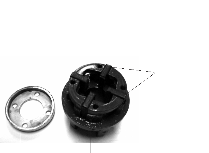
To replace the Die Blades: Worn Die Blades can result in poor thread quality. When 7.
replacing Die Blades, verify that the size of the new Die Blades correspond to the
size of the Die (1/2”, 3/4”, 1”, or 1-1/4”). To replace the Die Blades:
Remove the four Screws on the Die. a.
Remove the Chrome Ring from the Die.b.
Remove all four Die Blades.c.
Insert four new Die Blades into the Die. d. NOTE: When inserting the Die Blades,
make sure the cutting edges of the Die Blades face inward and that the number
on each Die Blade is at the top and in sequence.
Once the Die Blades are properly inserted, replace the Chrome Ring and four e.
Screws.
Chrome Ring Die
Die Blades

Page 13SKU 95955 For technical questions, please call 1-800-444-3353.
PARTS LIST
No. Part name
1 Baffle
2 Bearing Bushing
3 629 Bearing
4 Rotor
5 Ø28 Circlip
6 6001 Bearing 53 Soft
Cover
7 Ø5 Spring Washer
8 M5 X22 Cross Screw
9 Ø5 Flat Washer
10 Divider
11 M5X14 Cross Sunk Bolt
12 ST5 X 40 Cross Screw
13 Closing
14 Big Gear
15 S1102 Plane Bearing
16 RNA4902A Needle
Bearing
17 Bushing
18 Key
19 Worm Gear
20 RNA4900A Needle
Bearing
21 Ø65 Seal Ring
No. Part name
22 ST5 X 65 Cross Screw
23 Worm Speed Reducer
Gearbox
24 Ø55 Steel Wire Shield
25 Die Holder
26 Die Holder Cover
27 Bearing Bushing
28 Ø100 Seal Ring
29 Ø112 Seal Ring
30 Ø112 Snap Ring
31 Soft Cover
32 Soft Grip
33 ST4 X18 Cross Screw
34 ST4 X25 Cross Screw
35 Right Handle
36 ST4 X14 Cross Screw
37 Cable Retainer
38 Cable Plug
39 On/Off Trigger
40 Rotating Direction
Switch
41 Safety Handle
43 Coil Ring
44 Copper Spring
No. Part name
45 Reinforcing Ring Gasket
46 Brush Holder Cover
47 Carbon Brush
48 Brush Holder
49 Label
50 Housing
51 Stator
52 ST4X85 Cross Screw
53 Cable Protector
54 Clamp Assembly Nut
55 Clamp Assembly Rod
56 Clamp Assembly Clamp
57 Oil Can
58 1-1/4” Die
58A 1-1/4” Die Blades
59 1/2” Die
59A 1/2” Die Blades
60 3/4” Die
60A 3/4” Die Blades
61 1” Die
61A 1” Die Blades
PLEASE READ THE FOLLOWING CAREFULLY
THE MANUFACTURER AND/OR DISTRIBUTOR HAS PROVIDED THE PARTS LIST AND ASSEM-
BLY DIAGRAM IN THIS MANUAL AS A REFERENCE TOOL ONLY. NEITHER THE MANUFACTURER
OR DISTRIBUTOR MAKES ANY REPRESENTATION OR WARRANTY OF ANY KIND TO THE BUYER
THAT HE OR SHE IS QUALIFIED TO MAKE ANY REPAIRS TO THE PRODUCT, OR THAT HE OR
SHE IS QUALIFIED TO REPLACE ANY PARTS OF THE PRODUCT. IN FACT, THE MANUFACTURER
AND/OR DISTRIBUTOR EXPRESSLY STATES THAT ALL REPAIRS AND PARTS REPLACEMENTS
SHOULD BE UNDERTAKEN BY CERTIFIED AND LICENSED TECHNICIANS, AND NOT BY THE
BUYER. THE BUYER ASSUMES ALL RISK AND LIABILITY ARISING OUT OF HIS OR HER REPAIRS
TO THE ORIGINAL PRODUCT OR REPLACEMENT PARTS THERETO, OR ARISING OUT OF HIS
OR HER INSTALLATION OF REPLACEMENT PARTS THERETO.
Record Product’s Serial Number Here:________________________
Note: If product has no serial number, record month and year of purchase instead.
Note: Some parts are listed and shown for illustration purposes only, and are not available individually as
replacement parts.
REV 08b, 09e
Page 14SKU 95955 For technical questions, please call 1-800-444-3353.
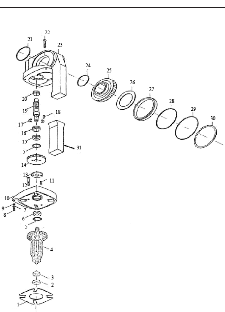
ASSEMBLY DIAGRAM
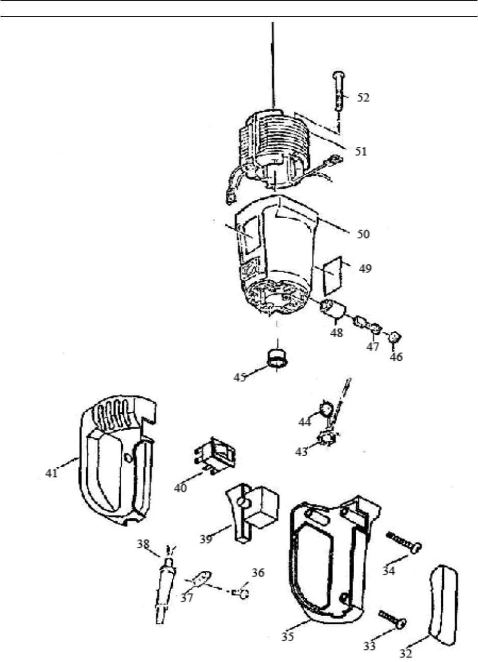
Page 15SKU 95955 For technical questions, please call 1-800-444-3353.
53
ASSEMBLY DIAGRAM
REV 09e

Page 16SKU 95955 For technical questions, please call 1-800-444-3353.
57 59 55 60 61 58 5654
LIMITED 90 DAY WARRANTY
Harbor Freight Tools Co. makes every effort to assure that its products meet high
quality and durability standards, and warrants to the original purchaser that this product
is free from defects in materials and workmanship for the period of 90 days from the date
of purchase. This warranty does not apply to damage due directly or indirectly, to misuse,
abuse, negligence or accidents, repairs or alterations outside our facilities, criminal activity,
improper installation, normal wear and tear, or to lack of maintenance. We shall in no event
be liable for death, injuries to persons or property, or for incidental, contingent, special
or consequential damages arising from the use of our product. Some states do not allow
the exclusion or limitation of incidental or consequential damages, so the above limitation
of exclusion may not apply to you. THIS WARRANTY IS EXPRESSLY IN LIEU OF ALL
OTHER WARRANTIES, EXPRESS OR IMPLIED, INCLUDING THE WARRANTIES OF
MERCHANTABILITY AND FITNESS.
To take advantage of this warranty, the product or part must be returned to us with
transportation charges prepaid. Proof of purchase date and an explanation of the com-
plaint must accompany the merchandise. If our inspection verifies the defect, we will either
repair or replace the product at our election or we may elect to refund the purchase price
if we cannot readily and quickly provide you with a replacement. We will return repaired
products at our expense, but if we determine there is no defect, or that the defect resulted
from causes not within the scope of our warranty, then you must bear the cost of returning
the product.
This warranty gives you specific legal rights and you may also have other rights
which vary from state to state.
3491 Mission Oaks Blvd. • PO Box 6009 • Camarillo, CA 93011 • (800) 444-3353
