Harbor Freight Mobile Folding Power Tool Stand Product Manual
2015-05-27
: Harbor-Freight Harbor-Freight-Mobile-Folding-Power-Tool-Stand-Product-Manual-723973 harbor-freight-mobile-folding-power-tool-stand-product-manual-723973 harbor-freight pdf
Open the PDF directly: View PDF ![]() .
.
Page Count: 5
Mobile / Folding
Power Tool Stand
40612
SET UP AND OPERATING INSTRUCTIONS
Distributed exclusively by Harbor Freight Tools®.
3491 Mission Oaks Blvd., Camarillo, CA 93011
Visit our website at: http://www.harborfreight.com
Read this material before using this product.
Failure to do so can result in serious injury.
SAVE THIS MANUAL.
Copyright© 1999 by Harbor Freight Tools®. All rights reserved. No portion of this manual or any artwork
contained herein may be reproduced in any shape or form without the express written consent of
Harbor Freight Tools. Diagrams within this manual may not be drawn proportionally. Due to continuing
improvements, actual product may differ slightly from the product described herein. Tools required for
assembly and service may not be included.
For technical questions or replacement parts, please call 1-800-444-3353.
Cover Revised 05e, 09c

SKU 40612 For technical questions, please call 1-800-444-3353. Page 2
SPECIFICATIONS
Maximum Extension Length 13’ x 10”
Table Top Dimensions 28” x 19-1/2”
Extension Wings Max. Width 57”
Overall Dimensions 22” x 52” x 37-3/4”
Wheel Diameter 7-3/4”
Roller Diameter 1-1/4”
Material Square Steel Tubing
Net Weight 71 lb.
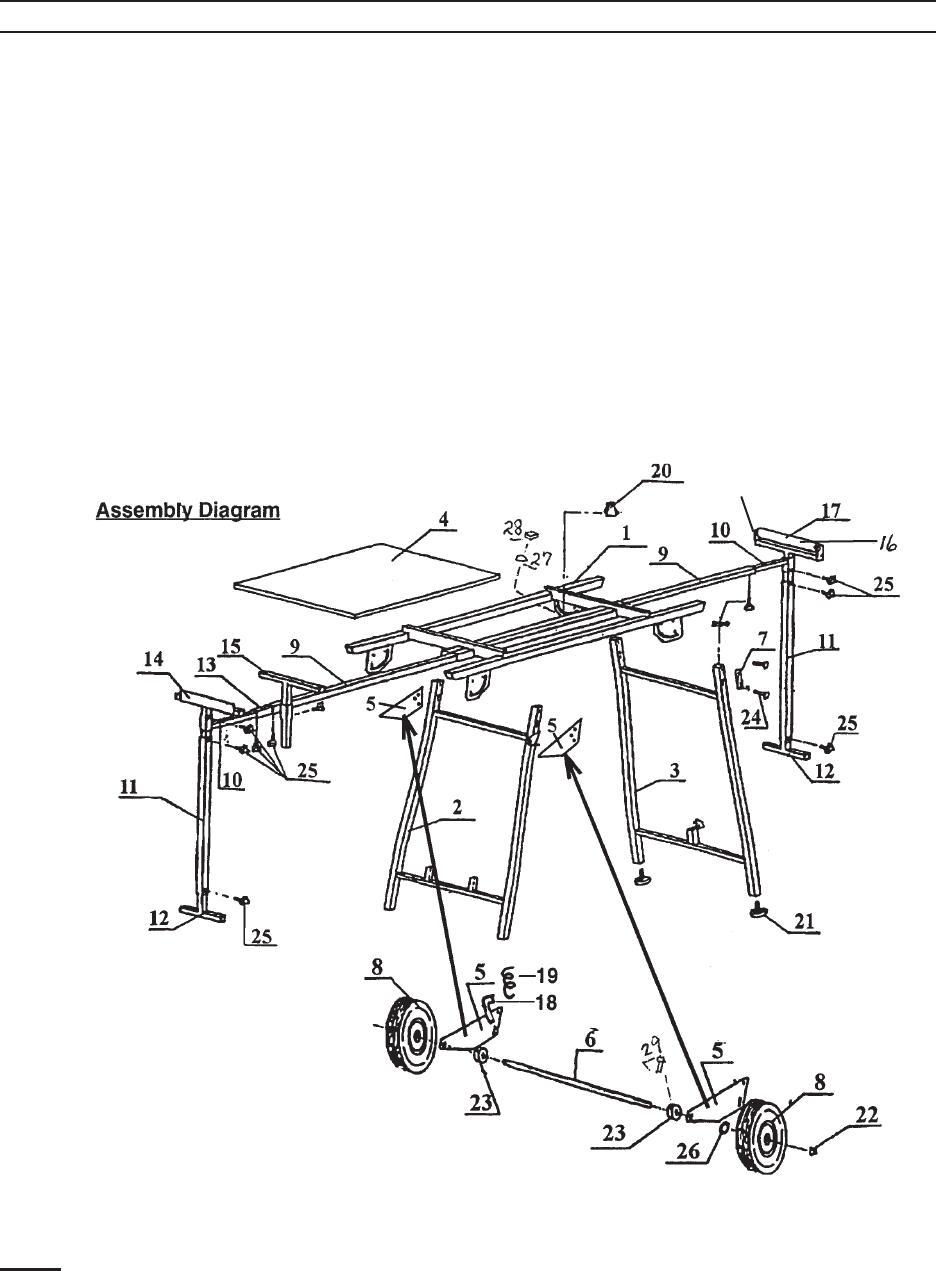
ASSEMBLY INSTRUCTIONS
Please refer to the Parts Diagram
to conrm identication of the parts dis-
cussed below. The Mobile/Folding Tool
Stand comes partially assembled. All that
remains is to attach the legs and wheels to
one end. It is best to have someone help
align the parts as you work. Lay the table
upside down at a comfortable working
height, and proceed as follows.
Slide one Latch Spring (#19) over 1. one Latch Pin (#18) until the spring
stops. Insert the spring end through
the large diameter hole on one side
of the leg assembly. The handle of
the Latch Pin should be toward the
outside of the square tubing.
Place the narrow end of the legs over 2. the outside of the pivot brackets that
are welded to the table frame -here
is where help is needed. Take one
Axle Plate (#5) and slide the small
round hole over the handle of Latch
Pin (#18). Note that the long straight
edge of the axle plate should be fac-
ing down, toward the table top. Hold
together tightly, and insert one Bolt
(#24) through the lower square hole
in the plate, the leg, and pivot brack-
et. Fasten loosely with one Washer
(#27) and one Locking Nut (#28).
Repeat this with the upper square
hole, but use a Locking Knob (#20)
on the thread in place of the lock nut.
This bolt goes through the curved slot
in the pivot bracket. Note how the
Latch Pin (#18) is meant to engage
the holes adjacent to either end of the
curved slot.
Repeat steps 1 and 2 on the other 3. side of the table. Install the Level-
ing Guides (#21) to the bottom of the
legs. Tighten the fasteners on both
sides of the leg assembly.
Insert Axle (#6) through one of the 4. Axle Plates (#5), then slide both Axle
Collars (#23) over the axle. Leave
loose for now. Slide end of axle
through the other Axle Plate. Install
Wheels (#8) on each side of axle,
and fasten with a Flat Washer (#26)
and Axle Bolt (#22). Slide each axle
collar next to the axle plates, and
tighten the Hex Bolt (#29).
By loosening the Locking Knobs 5. (#20) and pulling outward on the
Latch Pins, the legs can either be ex-
tended for use or folded for storage.
When folded, the table can be moved
about on the Wheels.
The table can be congured in mul-6. tiple ways by moving and adjusting
the stops and rollers to suit the ap-
plication.
Rev 00k

SKU 40612 For technical questions, please call 1-800-444-3353. Page 3
WARNING
Read All Instructions and warnings be-
fore using this product.
COMMON SENSE AND CAUTION ARE
FACTORS WHICH CANNOT BE BUILT
INTO ANY PRODUCT; THESE SAFETY
FACTORS MUST BE SUPPLIED BY THE
OPERATOR.
Select a level surface, free from ob-1. structions, when working with power
tools.
Properly anchor tools to the table 2. work surface before starting work.
Power tools must be bolted se-
curely to the Power Tool Stand
before using.
When folding or unfolding the stand, 3.
be careful not to pinch ngers.
Align all work supports with work 4. surfaces.
Wear ANSI-approved safety gog-5. gles during assembly.
Work supports must be within safe 6. operating limits, and locked into place
before starting power tools.
When working with long or heavy 7. workpieces (over 50 lb.) use addi-
tional supports.
Test your work set-up for stability 8. before beginning work.
Always unplug your power tool when 9. making adjustments or repairs to the
work set-up area.
Keep Work area Clean and unclut-10. tered. Clutter, grease and debris can
cause accidents.
Keep children away while tools are 11. being set up or in use.
Never leave power tools unattended 12. where children or unauthorized per-
sons can use them.
Do not exceed 550 lb. capacity. Be 13. aware of dynamic loading! Sudden
load movement may briey create
excess load causing product failure.
Do not operate power tools, or use 14. this product if over-tired or under the
inuence of drugs, alcohol or medi-
cines.
Do not wear loose clothing or jewelry 15. when operating power equipment.
Never reach over or across running 16. power tools.
Always check that adjusting wrench-17. es or keys are removed from any
machine before starting.
Check for alignment and binding 18. of all moving parts, broken parts or
other conditions that may affect safe
operation. Any damaged part should
be repaired or replaced by a qualied
technician.
Never force any tool or xture beyond 19. its design limits. This will damage the
tool, and may cause injury or property
damage.
When repairing this table or any tool, 20. use only factory original parts.
For replacement parts, contact
Harbor Freight Tools.
MAINTENANCE
Your Mobile / Folding Power Tool
Stand requires very little maintenance.
Keep it clean and dry, and occasionally
put a small amount of machine oil on the
threaded parts.
REV 09c
SKU 40612 For technical questions, please call 1-800-444-3353. Page 4
PLEASE READ THE FOLLOWING CAREFULLY
THE MANUFACTURER AND/OR DISTRIBUTOR HAS PROVIDED THE PARTS DIAGRAM IN THIS
MANUAL AS A REFERENCE TOOL ONLY. NEITHER THE MANUFACTURER NOR DISTRIBUTOR
MAKES ANY REPRESENTATION OR WARRANTY OF ANY KIND TO THE BUYER THAT HE OR SHE
IS QUALIFIED TO MAKE ANY REPAIRS TO THE PRODUCT OR THAT HE OR SHE IS QUALIFIED TO
REPLACE ANY PARTS OF THE PRODUCT. IN FACT, THE MANUFACTURER AND/OR DISTRIBUTOR
EXPRESSLY STATES THAT ALL REPAIRS AND PARTS REPLACEMENTS SHOULD BE UNDERTAKEN
BY CERTIFIED AND LICENSED TECHNICIANS AND NOT BY THE BUYER. THE BUYER ASSUMES
ALL RISK AND LIABILITY ARISING OUT OF HIS OR HER REPAIRS TO THE ORIGINAL PRODUCT OR
REPLACEMENT PARTS THERETO, OR ARISING OUT OF HIS OR HER INSTALLATION OF REPLACE-
MENT PARTS THERETO.
Note: Some parts are listed and shown for illustration purposes only, and are not avail-
able individually as replacement parts.
30
Rev 01a

SKU 40612 For technical questions, please call 1-800-444-3353. Page 5
Part Description Qty
1 Top Frame 1
2 Left Leg Assembly 1
3 Right Leg Assembly 1
4 Table Top 1
5 Axle Plate 2
6 Axle Shaft 1
7 Leg Plate 2
8 Wheel 2
9 Outrigger - 1” sq. 2
10 Outer Extension 2
11 Support Leg 2
12 Adjustable Foot 2
13 Adaptor Tee 1
14 Posi-stop Tee 1
15 Support Tee 1
Part Description Qty
16 Support Roller Tee 1
17 Roller 1-3/8” x 10” 1
18 Latch Pin 2
19 Latch Spring 2
20 Locking Knob 4
21 Leveling Glide 2
22 Axle Bolt 1/2” x 20 2
23 Axle Collar 2
24 Carriage Bolt 1/4” x 20 x 1.75” 8
25 Locking Knob 5/16” male 12
26 Flat Washer 1/2” 2
27 Flat Washer 1/4” 14
28 Self Locking Nut 1/4” 8
29 Hex Bolt 1/4” x 20 x 2
30 Locking Pin for Roller 2
PARTS LIST
Rev 01a
