Harman Becker Automotive Systems BE2810 Automotive Infotainment Unit User Manual
Harman Becker Automotive Systems, Inc. Automotive Infotainment Unit
Contents
- 1. 09a_User Manual_Part1
- 2. 09b_User Manual_Part2
09a_User Manual_Part1
Owner's manual
Important note
For information on the location of Ferrari Dealers and Authorised
Service Centres, visit the website www.ferraridealer.com or the
Customer Care Service available at the numbers indicated in the
“Reference Guide” booklet.


4Introduction
General remarks
This vehicle, which complies with EC homologation parameters,
uses advanced technology and is capable of achieving high
performance levels.
It is equipped with sophisticated active and passive safety
systems (described below).
These safety features and systems do not authorise the driver
to take risks other than those involved in normal driving since
their preventive and protective action is guaranteed only in
certain conditions. Unless otherwise instructed specifically by
Ferrari (see the Safety chapter), the deactivation of any of the
vehicle’s safety systems is PROHIBITED.
While certain safety systems (e.g. the airbags) have been
tested to ensure that they offer the highest possible levels of
protection, they may nonetheless be hazardous in the event of
failure by the driver or passenger to observe the instructions
given by Ferrari. All vehicle occupants must be attentive at
all times and take particular care when transporting passengers
who are more subject to injury such as children, disabled and
elderly persons.
Safe driving is subject to the following conditions AT ALL TIMES:
- the driver must be in perfect psycho-physical condition;
- road regulations (Traffic Regulations - Vienna Convention
on Road Traffic that ended on 8 November 1968) must be
strictly observed;
- common rules of caution must always be observed in relation
to the quality/performance of the vehicle, driving conditions
and contingent situations.
- Caution and discipline are the basis of safe driving.
- Driving takes place in a naturally dangerous context in which
a number of different risk factors interact. For this reason,
drivers must drive bearing in mind that others, whether they
are pedestrians, motorcyclists or motorists, can make mistakes.
Keeping a safe distance allows emergency measures to be
taken. Remember that national and international legislation
requires that the driver of the vehicle must be capable of
performing corrective and/or emergency manoeuvres at all
times.
- Correct and careful use of a vehicle derives, above all, from
respect for one's own safety and that of others as well as
from compliance with road regulations. Only this respect will
help you experience all the emotions that driving this car can
offer you.
The driver MUST NEVER allow passengers to increase the
risks associated with driving (e.g. by not using safety systems
such as the seat belts) by failing to observe the mandatory
safety rules that apply to both driver and passengers.
The vehicle MUST NOT be modified or tampered with for
any reason whatsoever since, by so doing, the manufacturer's
homologation and safety parameters will be modified.

5
Introduction
The driver must pay the utmost attention to the signals of the
vehicle and, in particular, the warning lights on the dashboard
and buzzers. Even when the warning lights do not indicate a
situation of immediate danger, the driver must be cautious in
relation to possible consequences/degeneration of the failure
and other information given.
During routine operations, such as refuelling, precautions
should always been taken and it is important to check that
flammable liquid has not been spilled; these precautions must
be observed even if the operation is performed by others.
Similarly, before setting off make sure that the doors are
closed by checking the warning lights and also manually.
The driver must be fully acquainted with the vehicle and its
controls in order to handle and drive it correctly. Command of
the vehicle can be acquired/improved by attending the driving
courses held by Ferrari which we strongly recommend.
The use of terms from the motor sports world (such as F1,
SPORT and RACE) is merely indicative of the vehicle's
competition-derived technology and does not endorse
inappropriate behaviour on the road which does not comply
with Traffic Regulations.
Sports-style or SPORT or RACE mode driving refer to road
driving.
Most accidents are caused by distraction. The driver must use
any on-board information, communication and entertainment
systems responsibly, especially when the vehicle is in motion.
Examples of information, communication and entertainment
systems are the following: satellite navigation systems, traffic
information systems (e.g. ITT), media players (e.g. iPod),
telephones with Bluetooth connectivity, etc. (whether merely
audio-based or with display).
It is important to bear in mind that on-board systems may
be distracting when driving since they may take a driver's
attention off the road for several seconds.
Aftermarket video entertainment systems for the passenger (e.g.
TV) must be installed where they cannot distract the driver
while the vehicle is in motion. While the vehicle is in motion,
the attention required to use on-board systems must never
exceed the high level of attention required to drive safely in
accordance with the Traffic Regulations.
Therefore, these systems may only be used (separately or in
combination with others) by the driver:
- in complete safety (stopping the vehicle before use if
necessary). Operations that are not involved with driving
(e.g. changing dashboard functions), must be performed in
maximum safety when the vehicle is stationary;

6Introduction
- putting road safety first; for example, under conditions of
poor or limited visibility, looking at a display with active
programmes can be distracting even if you take your eye off
the road only for a split second;
- ensuring, if the previous vehicle owner has installed systems
on the vehicle that are NOT APPROVED by Ferrari (car
tuning), that they are fully compatible with the original
vehicle equipment.
If the vehicle owner has installed one or more new systems, either
fixed or removable, on the vehicle, make sure that these
- have the necessary certification;
- are fully compatible with the original vehicle equipment (i.e.
they do not interfere with it);
- are fitted by skilled staff.
The Ferrari Technical Service Department and Ferrari
Dealers and Authorised Service Centres can provide all the
information needed to ensure that they are compatible.
Strict priority criteria must be observed when driving a vehicle: you
must not therefore take your attention off the road.
In some countries, the use of entertainment/information systems is
prohibited on vehicles when driving.
The driver is responsible for use of these entertainment/
information systems with video screens if they are prohibited in the
country where the vehicle will be driven.
These considerations are not exhaustive, but only refer to
some general issues that will be specifically dealt with in this
Owner's Manual.

7
Introduction
Introduction
The aim of this Owner’s Manual is to help you get the best
value from your vehicle and to provide information on routine
maintenance: we advise you to read it carefully before setting
out. The Owner’s Manual should be considered an integral part
of the vehicle and must therefore always be kept on board.
Using the product in a way that does NOT comply with
the Owner's Manual not only exonerates Ferrari of any
responsibility but also puts the person at great risk.
Due to its performance characteristics, the vehicle should not
be driven by inexperienced drivers who have not received
proper training.
Special care should be taken when giving the vehicle to third
parties so that they are not put at risk. The vehicle can also
be damaged if used in a way that does not comply with the
instructions given above.
Updating
The high quality level of the vehicle is subject to constant
technological improvements. Therefore, there may be
differences between this manual and your vehicle.
The Ferrari Sales and Service Network will provide you
with all the information on any updates.
All specifications and illustrations contained in this manual are
accurate as of the date of printing.
Spare parts
When replacing parts or topping up with lubricants and fluids,
we recommend that you use original spare parts and lubricants
and fluids recommended by Ferrari.
Warranty Booklet
Each new vehicle comes with a “Warranty Booklet”.
This contains the vehicle’s warranty validity conditions.
This warranty does not affect the buyer's statutory rights as a
consumer, which derive from binding legal norms in his or her
favour, in the various states or countries, or from European
Union regulations, towards the Dealer.
The Warranty Booklet also contains the routine maintenance
indicated in the “Maintenance Schedule”.

8Introduction
Consulting the manual
To facilitate reading the manual, the topics have been divided
into sections and chapters.
1. General
Provides general information about your vehicle.
2. Safety
Describes the main safety systems in the vehicle.
3. About your Vehicle
Provides all necessary information for use of the vehicle.
4. Advice for Emergency Situations
Provides useful advice for solving problems that may occur.
5. Care of the vehicle
Provides advice for cleaning, care and routine maintenance of
your vehicle.
6. Glossary
Explains the main technical concepts.
7. Table of Contents
Allows you to quickly identify and locate the information
required.
Service
The information in this manual is necessary for the use and
proper care of the vehicle. In addition, Customers will get
maximum satisfaction and results from the vehicle if they
carefully follow the instructions contained in it.
We recommend that you have all the checks and services
performed at Ferrari Authorised Workshops since they have
highly skilled staff and the necessary equipment.
In the case of erroneous maintenance or repairs (that do not
conform to the technical repair standards and procedures
adopted by Ferrari), undertaken by independent repair
centres, particularly if concerning safety systems or safety,
Ferrari may decide to not carry out further repairs on the
vehicle, unless the vehicle is restored so that it conforms to
original parameters.
The Customer Care Service, available at the numbers indicated
in the “Reference Guide” booklet enclosed with the vehicle
documents, can provide information on the location of the
Ferrari Dealers and Authorised Service Centres.
The Ferrari Technical Service Department is at your
complete disposal for any information and advice. If you have
any doubts about the information provided in this manual or
how to use or operate the vehicle, please contact the Ferrari
Service Network.
9
Introduction
Environment
Warning for environmental protection: useful advice for protec-
tion of the environment.
Within the various sections, special attention must be paid to
the parts marked as follows:
Warning
Extreme caution required: failure to comply with the
instructions could constitute a serious risk to personal safety
and vehicle protection!
Important note
Important note: a note containing instructions or information.
10 Introduction
Environmental protection
Environment
The following chapter contains useful advice for environmental
protection.
Ferrari has designed and constructed a vehicle using technologies,
materials and devices capable of reducing the harmful impact on
the environment to a minimum.
If you use your vehicle with respect for the environment, you too
will contribute to environmental protection.
Fuel consumption as well as engine, gearbox, brakes and tyres wear
mainly depend on two factors:
- use of the vehicle;
- driving style.
Both factors are influenced by the driver.
Use of the vehicle
- Avoid using the vehicle for short trips.
- Check that the tyre pressure is correct.
- Check the fuel consumption.
- Proper periodic maintenance will contribute to preserving your
vehicle in full working order and to protecting the environment.
We therefore advise you to respect the service due dates indicated
in the “Maintenance Schedule”.
Driving style
- Do not accelerate during the starting procedure.
- Do not warm up the engine when the vehicle is stationary.
- Drive carefully and keep a safety distance that corresponds to the
driving speed.
- Avoid sudden and frequent acceleration or braking
- Turn off the engine if the vehicle is kept stationary for long peri-
ods of time.
- Shift gears using only 2/3 of the speed permitted for each gear.
- Use the air conditioning in moderation.
- A driving style like that described above protects the vehicle
from premature wear and tear, makes driving safer and does not
subject the vehicle to undue fatigue.
Important note
The vehicle is equipped with exhaust gas control and monitor-
ing systems which must always be kept in perfect working order
and controlled regularly.
11
Introduction
Directive for the treatment of end-of-life vehicles
(EU only)
For many years, Ferrari has been globally committed to respecting
and protecting the environment by constantly improving its
manufacturing processes and developing increasingly eco-
compatible products.
Regulations for the treatment of end-of-life vehicles, implemented
in response to the terms of EU Directive 2000/53, require that
producers (manufacturers and official importers) collect all the
vehicles introduced on the market by the producers themselves
at the end of their life cycle, and ensure that these vehicles are
processed in an environmentally compatible manner.
To hand over your Ferrari at the end of its life cycle for treatment
at no additional cost (excluding deregistration and transport), take
your vehicle to the nearest Ferrari dealer, which will, at its own
expense, transport the vehicle to one of the authorised collection
and demolition centres, which have been selected to ensure that all
processes for the collection, treatment and recovery of recyclable
materials are carried out in an environmentally compatible manner.
For further information, visit www.ferrari.com.
When handing over a Ferrari vehicle at the end of its life cycle:
- the vehicle must be complete, containing all the essential
elements such as the engine, transmission, bodywork, ECUs
and catalytic converters;
- the vehicle must not contain any additional refuse.
Ferrari is committed to offering its clients a geographically
extensive and, as a result, better service, and thanks you for your
cooperation in this environmental challenge.
Bear in mind that specific regulations govern the disposal of vehicle
parts including batteries, tyres, used oil, etc.
Please contact the Ferrari Service Network for more
information.

1. General
2. Safety
3. About your Vehicle
4. Advice for Emergency Situations
5. Care of the vehicle
6. Glossary
7. Table of Contents
14 General
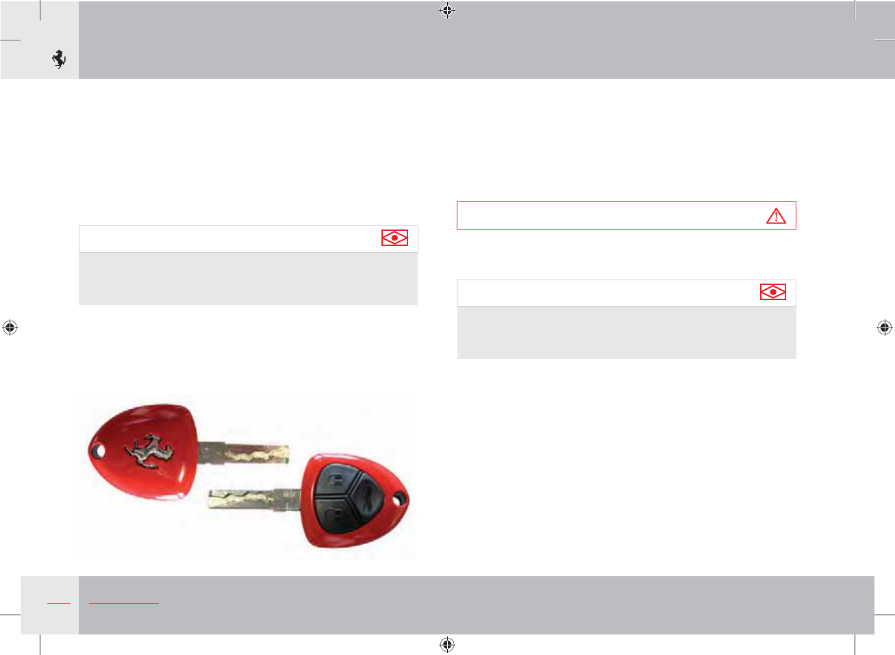
Vehicle keys
The vehicle is delivered with two identical keys that can be used
for:
- central door locking;
- starting the vehicle;
- activating/deactivating the alarm system;
- opening the luggage compartment.
Important note
If the keys are lost or stolen, you can request a duplicate from
the Ferrari Service Network (see section “Duplicating the
keys” on page 16).
Key codes
A CODE CARD is supplied together with the keys, indicating the
following:
- the electronic code;
- the mechanical code for the keys, to be given to the Ferrari
Service Network if you request duplicates of the keys.
Warning
The code numbers on the CODE CARD must always be kept in
a safe and protected place, not accessible to others.
Important note
In the event of a change of ownership, it is essential that the
new vehicle owner is provided with all the keys and with the
CODE CARD.
15
General
1
Alarm system
The FERRARI CODE system
The vehicle is equipped with an electronic immobiliser system
(Ferrari CODE) which is automatically activated when the ignition
key is removed.
The keys are equipped with an electronic device which transmits
a coded signal to the Ferrari CODE ECU. Once this ECU has
recognised the signal, it allows the engine to start.
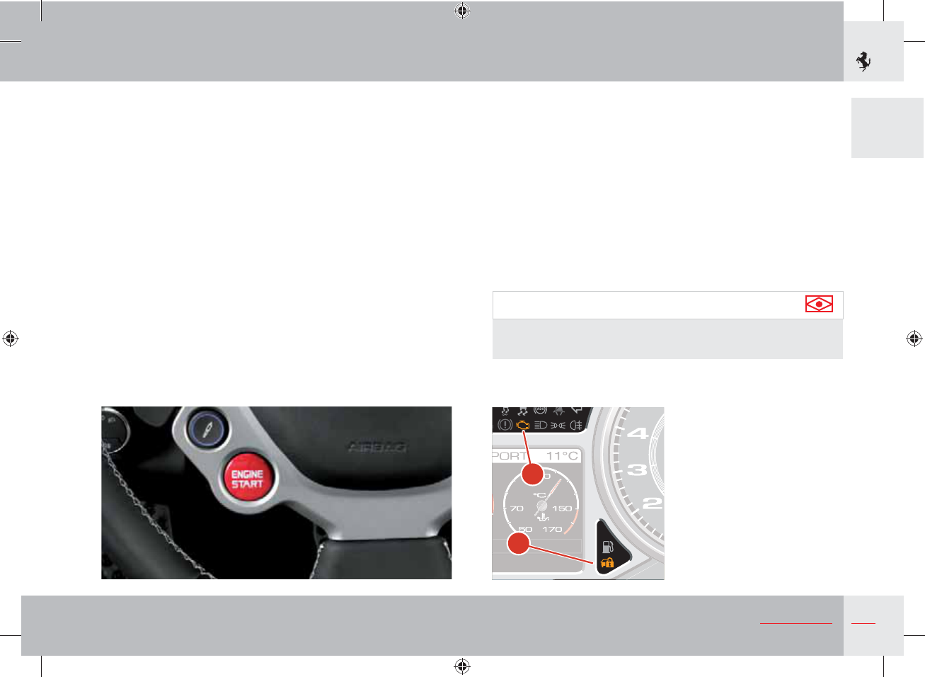
Operation
Each time the ignition key is removed from position 0 (see
page 85), the protection system activates the engine immobiliser.
- When starting the engine, press the ENGINE START button on
the steering wheel:
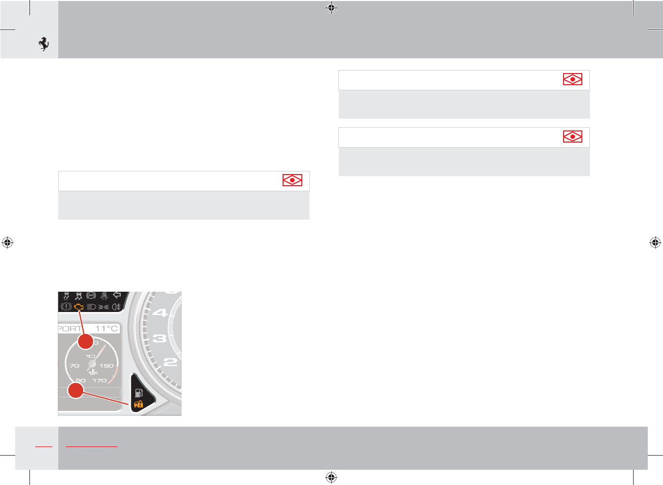
1) If the code is recognised, the CODE warning light A on the
instrument panel turns off when the check procedure has been
completed, whereas the EOBD warning light B turns off when
the engine is started once the ECU has completed its diagnostic
cycle; in these conditions, the protection system has recognised
the key code and deactivated the immobiliser.
2) If the CODE warning light A stays on, it means that the code
has not been recognised. If this occurs, it is advisable to turn
the key back to position 0 and then back to II; if the immobiliser
device remains active, try with the other key provided.
Important note
If you still cannot restart the engine, contact the Ferrari
Service Network.
B
A
16 General
- While driving, with the ignition key in position II:
1) If the CODE A warning light turns on, it means that the system
is performing a self-diagnostic cycle. At the first opportunity,
you can stop and test the system: switch off the engine by
turning the ignition key to position 0, then turn the key back to
position II: the CODE warning light A will turn on and should
go off within one second. If the warning light stays on, repeat
the procedure described previously leaving the key at 0 for
more than 30 seconds.
Important note
If the problem persists, please contact the Ferrari Service
Network.
2) If the CODE warning light A flashes, it means that the vehicle is
not protected by the immobiliser.
Important note
Contact the Ferrari Service Network immediately to have all
the keys stored in the system memory.
Important note
Each key provided has its own specific code, which must be
stored in the memory of the system control unit.
Duplicating the keys
If you request additional keys, provided that the conditions to
satisfy your request are met, remember that the codes must be
stored (up to a maximum of 7 keys) on all the keys.
Contact the Ferrari Service Network directly and bring the
following with you:
- all the keys in your possession;
- the CODE CARD for the Ferrari CODE system;
- a personal identity document;
- the documents proving ownership of the vehicle.
The codes for the keys that are not available when the new
memorisation procedure is performed will be deleted from the
memory to prevent any lost or stolen keys being used to start the
vehicle.
B
A
17
General
1
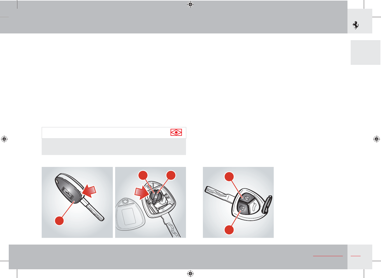
Replacing remote control batteries
If you press one of the three buttons on the key and this does not
activate the corresponding function, check that the alarm system
functions are operating correctly by using the other remote control
before replacing the remote control batteries.
Replace the remote control batteries as follows:
- open the key cover C using a small screwdriver at the position
indicated by the arrow;
- remove the two batteries E, pushing in the direction indicated by
the arrow to release them from the retainer cover D;
- fit two new batteries of the same type, observing the indicated
polarity;
- close the key cover C.
Important note
Do not use sharp tools to remove the cover and be careful to
avoid damaging the remote control.
Electronic alarm
The electronic alarm system performs the following functions:
- remote control for central door locking/unlocking;
- perimeter surveillance, detecting if doors and lids are open;
- motion surveillance, detecting intrusion in the passenger compartment;
- vehicle movement surveillance.
Activation
To activate the alarm system, press button F on the ignition key:
- the turn indicators flash once;
- the system “beeps”;
- the red LED on the dashboard flashes;
- the central door locking system of the vehicle is activated and the
doors are locked.
The system activates after approximately 25 seconds.
When the electronic alarm is activated, the user may request
opening of the luggage compartment; in this case, the motion and
anti-lift sensors are temporarily deactivated.
$
& %
(
'
18 General
If the luggage compartment is then closed, the sensors will be
reactivated.
If the turn indicators and the red LED on the dashboard flash
9 times when you activate the alarm system, it means that one of
the doors or the front/rear lid is open or not closed properly and is
therefore not protected by the perimeter surveillance. If this is the
case, check that the doors and front/rear lids are closed properly
and close any door or lid that is open without deactivating the
alarm system: the turn indicators will flash once to indicate that the
door and front/rear lids are now closed properly and protected by
the perimeter surveillance.
Warning
If the turn indicators and the red LED on the dashboard flash
9 times when the alarm system is activated with the doors and
front and rear lids properly closed, it means that the self-diag-
nostic feature has detected a malfunction in the system. Contact
the Ferrari Service Network to have the system checked.
Deactivation
To deactivate the alarm system, press button G on the ignition key:
- the turn indicators flash twice;
- the system beeps twice;
- the red LED on the dashboard goes off;
- the cabin lights and the puddle lights come on;
- the central door locking system of the vehicle is deactivated and
the doors are unlocked.
Pressing button G twice unlocks the doors and also turns on the
low beams for 30 seconds.
The alarm system is off and you can now get into the vehicle and
start the engine.
To enter the vehicle if the remote control battery is flat, insert the
key into one of the two door locks and turn it to release the lock;
the alarm siren will activate.
Start the vehicle following the standard procedures; The alarm
siren will deactivate.
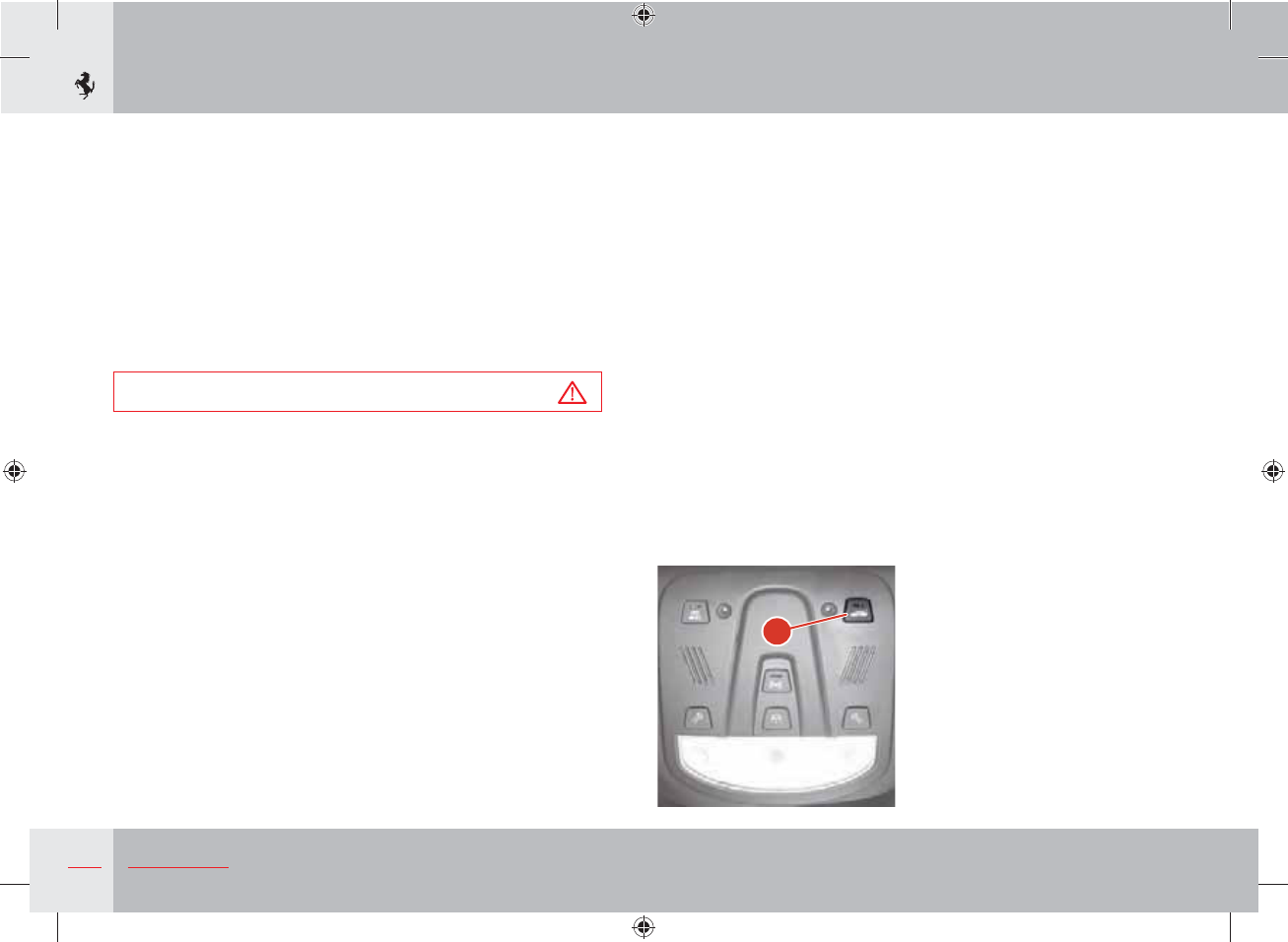
Deactivating the anti-lift volumetric alarm
Press button H to deactivate the volumetric sensors and anti-lift
alarm system. When this function is deactivated, the indicator light
on the button will flash for about 3 seconds and will then turn off.
H
19
General
1
Alarm memory
If, when the vehicle is started, the CODE symbol (see page 148)
appears on the TFT display for 10 seconds after the system
diagnosis cycle, together with the message “Break-in attempted”,
this means there has been an attempt to break into the car, causing
the alarm to activate.
In this case, the system will indicate the reason for the alarm
activation according to the following priority:
- LED off twice: anti-lift sensor alarm;
- LED off three times: door alarm;
- LED off four times: luggage compartment lid alarm;
- LED off five times: ignition key alarm.
The alarm system memory is reset by turning the ignition key.
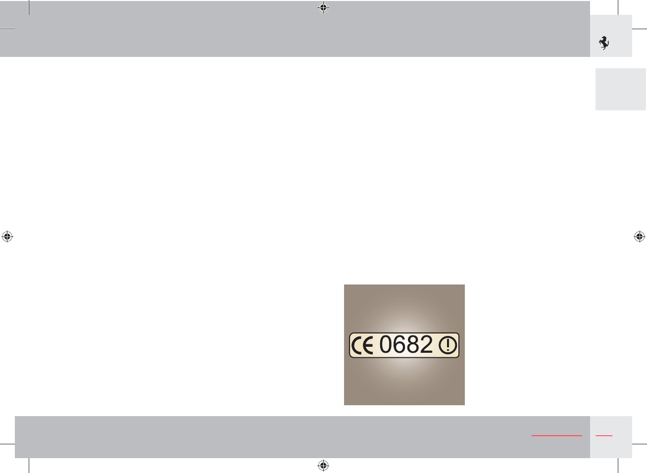
Ministerial homologation
The electronic alarm system complies with EU regulations on elec-
tromagnetic compatibility and is marked in compliance.
The homologation number is referred to with the following charac-
ters.
For those markets that require the transmitter and/or receiver
marking, the homologation number is found on the component.
Satellite alarm system (optional)
In some markets, the vehicle can be equipped, on request, with
a satellite alarm system. If the vehicle is equipped with a satellite
alarm system, please refer to the “Nav Trak Satellite Alarm System
Quick Reference” booklet enclosed with the vehicle documents, for
further information.
20 General
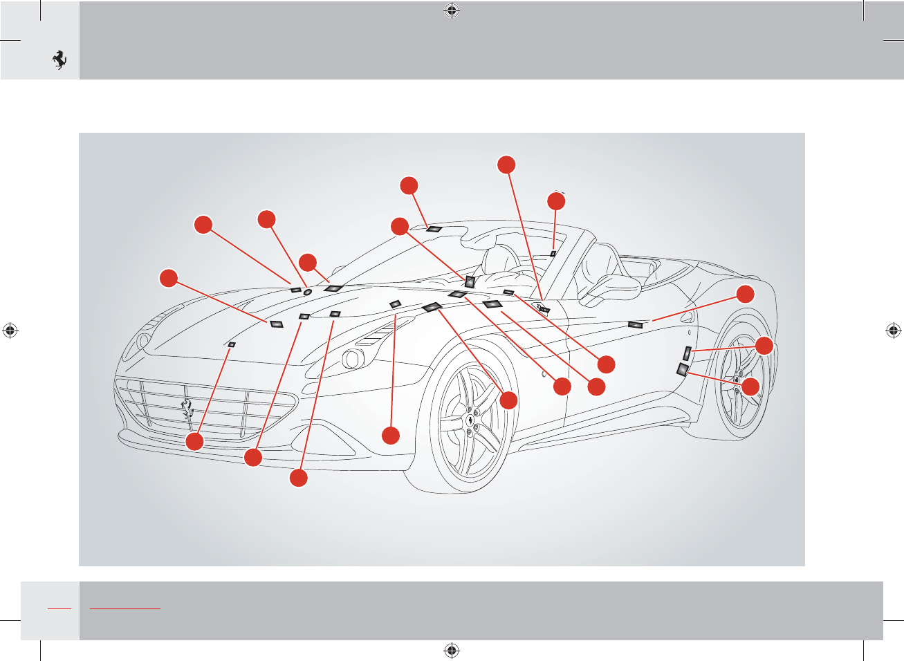
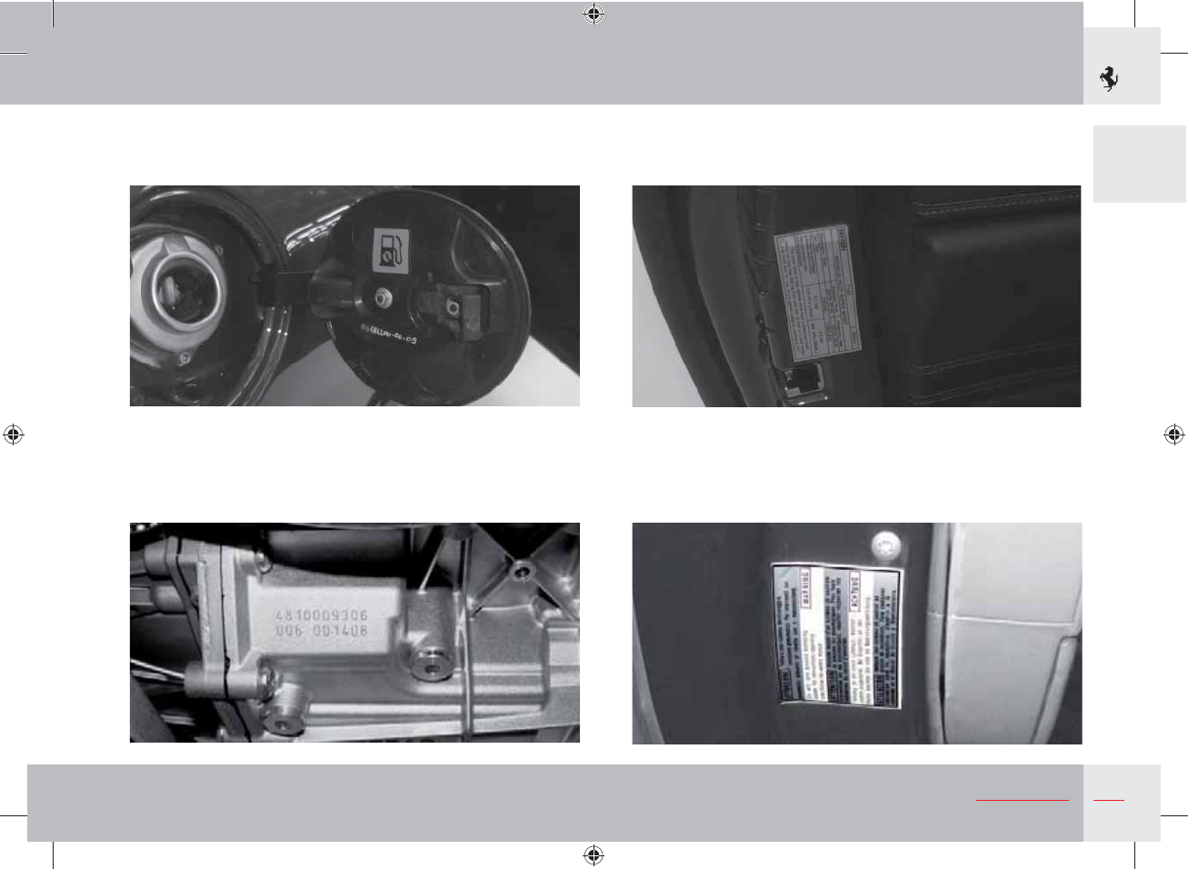
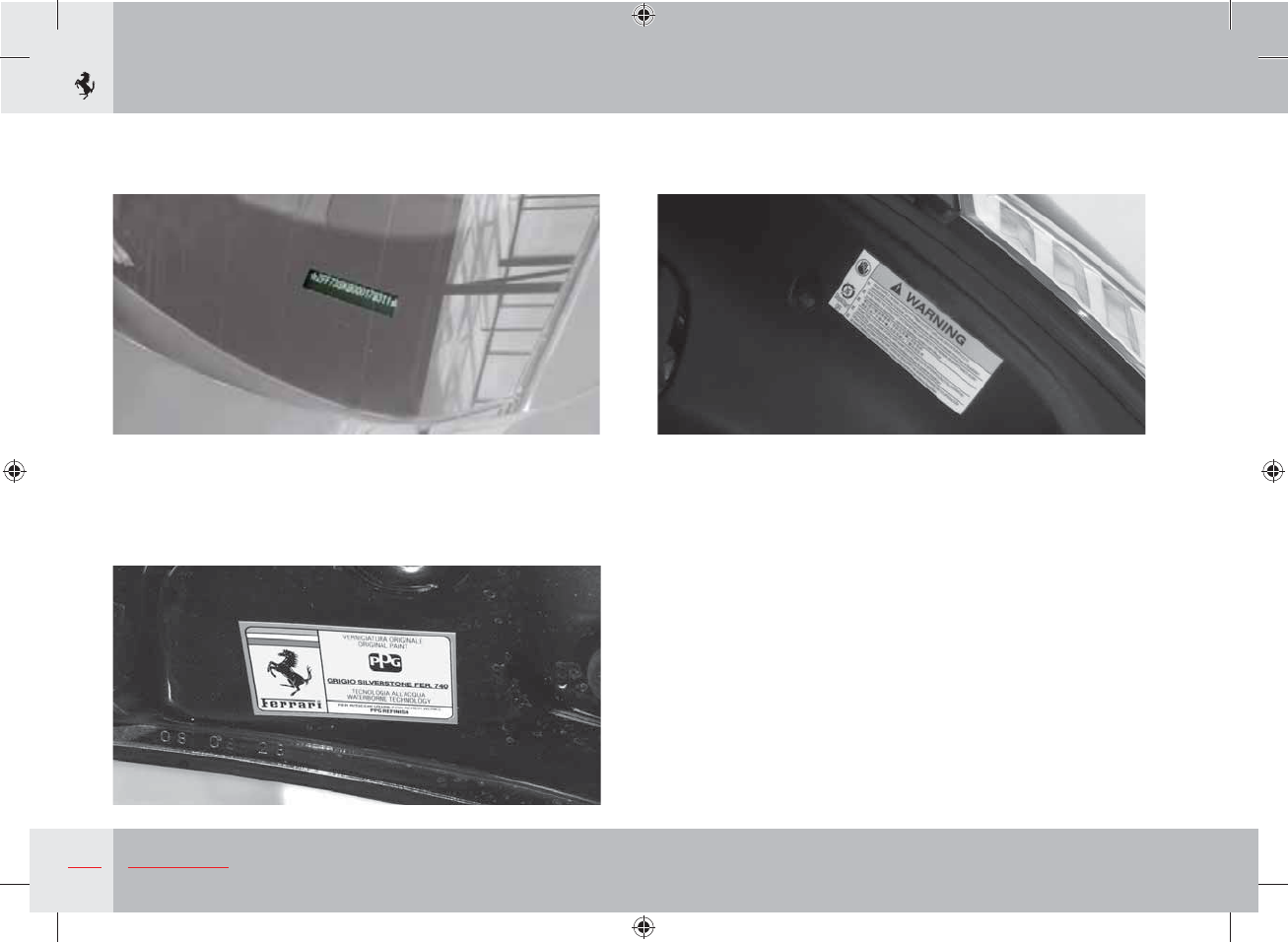
Identification and homologation plates and labels
R
L
S
Q
O
M
I
H
G
F
E
D
C
B
A
N
P
T
U

21
General
1
Ref. Label/plate Position
AEngine type and number Crankcase
BLow-beam homologation Engine compartment lid
CAssembly number Engine compartment
DRadiator with antifreeze RH engine compartment cosmetic shield
EChecking the engine oil level RH engine compartment cosmetic shield
FEngine and gearbox oil label RH engine compartment cosmetic shield
GECE homologation Engine compartment lid
HHigh voltage Central engine compartment cosmetic shield
IInstallation of rearward facing child seat not allowed Passenger-side dashboard side panel
LVehicle identification Rear passenger-side door jamb
MPassenger airbag warning (2) Passenger-side sun visor
NChassis number Chassis right-hand rear cross member
OUnleaded fuel Fuel filler flap
PGearbox type and number Gearbox housing
QTyre pressure and type Driver-side door
RTPMS present warning Driver-side door
SChassis number Windscreen
TOriginal paintwork Engine compartment lid
UStop&Start system warning (only with HELE) LH engine compartment cosmetic shield
22 General
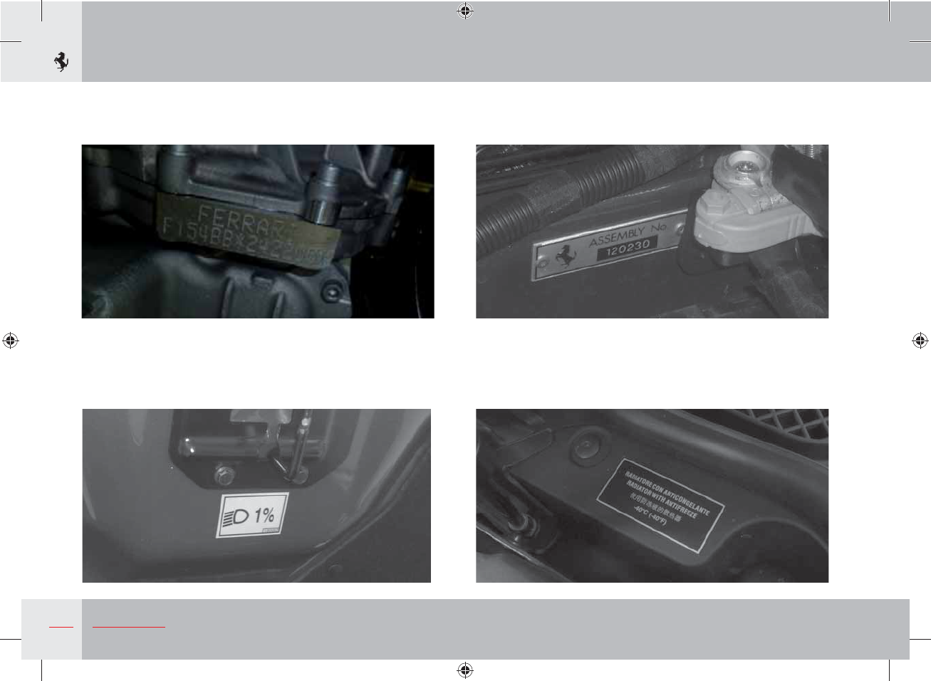
A Engine type and number
B Low-beam homologation
C Assembly number
D Radiator with antifreeze
23
General
1
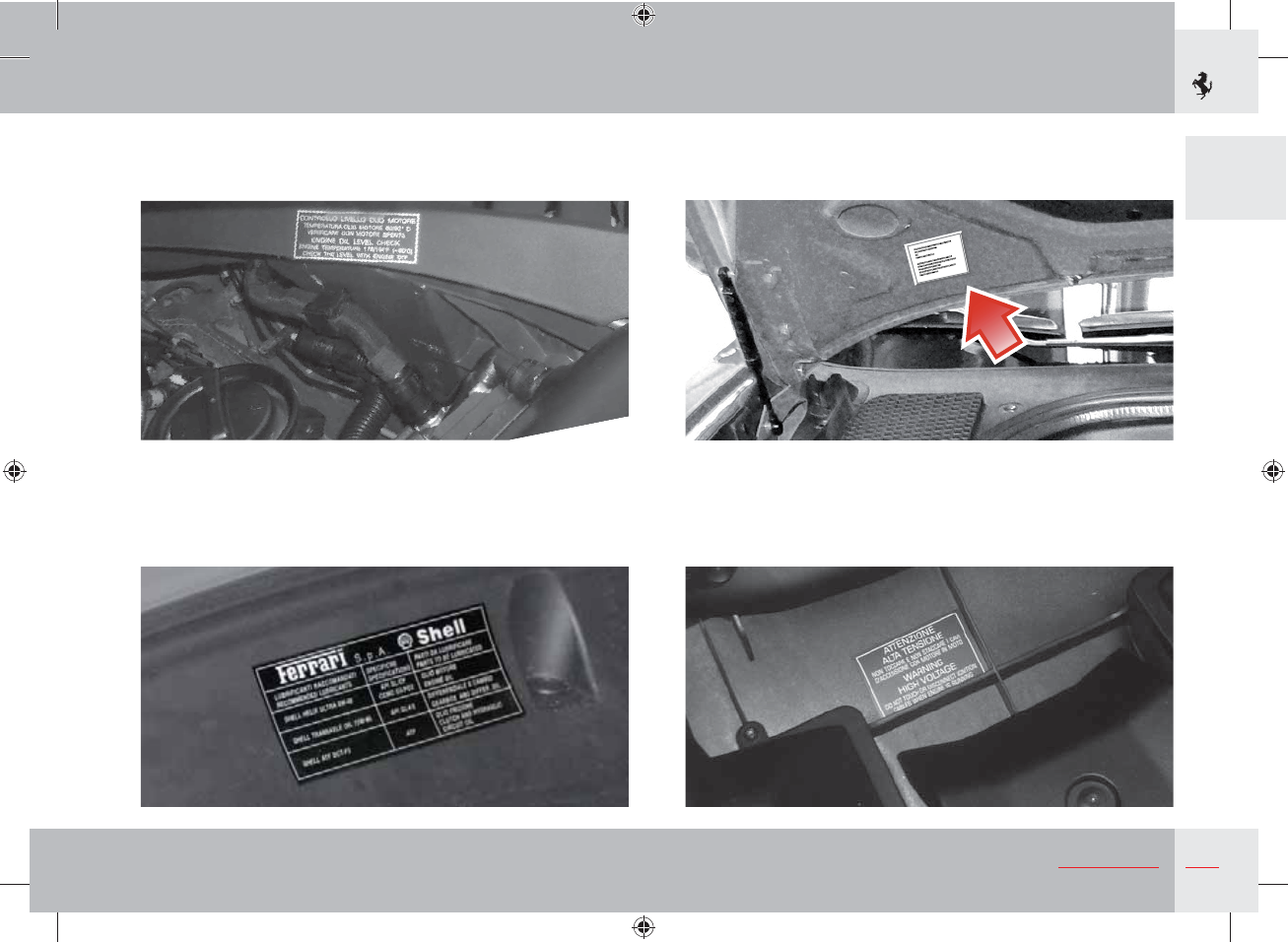
E Checking engine oil level
F Engine and gearbox oil label
G ECE homologation
H High voltage
24 General
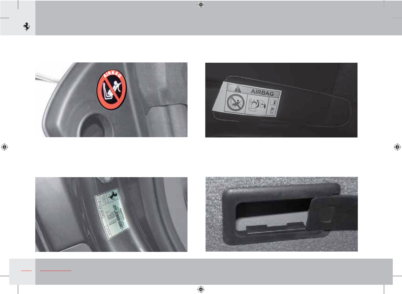
I Installation of rearward facing child seat not allowed
L Vehicle identification
M Passenger side airbag warning (2)
N Chassis number
25
General
1
O Unleaded fuel
P Gearbox type and number
Q Tyre pressure and type
R TPMS present warning
26 General
S Chassis number
T Original paintwork
U Stop&Start system warning (with HELE package only)
27
General
1
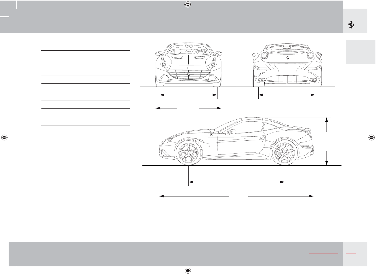
Dimensions and weights
Wheelbase 2670 mm
Max. length 4570 mm
Max. width 2109 mm
Max. height 1317 mm
Front track 1630 mm
Rear track 1605 mm
Front overhang 954 mm
Rear overhang 946 mm
Kerb weight 1770 kg *
* considering the most favourable OPT
combination
2109
1317
1605
1630
2670
4570
28 General
Main engine specifications
Type F 154 BB
Number of cylinders 8
Cylinder sequence V 90°
Cylinder bore 86.5 mm
Piston stroke 82 mm
Total displacement 3885 cm3
Compression ratio 9.4:1
Max. RPM
(with limiting device)
7500 RPM
Max. power
(Dir. 1999/99/EC)
412 kW
(560 hp) *
Corresponding RPM 7500 RPM
Max. torque
(Dir. 1999/99/EC)
755 Nm
Corresponding RPM 4750 RPM
Consumption and CO2 emissions
Standard
version
With
HELE system
l/100 km g/km l/100 km g/km
City cycle 17.8 415 15.5 362
Motorway 8.2 191 8.0 187
Combined cycle 11.7 273 10.7 251
Transmission ratios
Gearbox ratios Differential/bevel gear
pair ratio
1 = 3.397
2 = 2.185
3 = 1.626 4.444
4 = 1.286
5 = 1.028
6 = 0.839
7 = 0.634
R = 2.791
Performance
0 - 100 km/h Max. speed
3.6 s > 315 km/h
Electrical system
Supply voltage Alternator
12 V Nippondenso 150 A SC2
Battery Starter motor
Fiamm 12V - 100 A/h - 850 A Nippondenso
*: value obtained with 98 RON unleaded fuel
29
General
1
Wheel rims and tyres
Wheel rims
Front Rear Space saver spare wheel
8” J x 19” ET 44 10” J x 19” ET 52.5 4.5” J x 20”
8” J x 20” ET 44 10” J x 20” ET 52.5 4.5” J x 20”
Explanation of wheel rim codes
Example: 8” J x 20” ET 44
8” = Rim width in inches
J = Shape of rim edge (side projection where tyre bead rests)
20” = Rim diameter in inches
ET 44 = Offset (distance, in mm, between the centreline of the rim and inner rim surface)
30 General
Ferrari-approved tyres Inflation pressure
(cold)
*
*
*
Pirelli PZero Front 245/40 ZR19 2.40 bar E B 71 dB
Rear 285/40 ZR19 2.20 bar E B 73 dB
Pirelli PZero Front 245/35 ZR20 2.20 bar E B 72 dB
Rear 285/35 ZR20 2.00 bar C B 73 dB
Optional tyres Inflation pressure
(cold)
*
*
*
Bridgestone RE050A
(Run-Flat)
Front 245/35 ZR20 2.40 bar F C 73 dB
Rear 285/35 ZR20 2.40 bar E B 72 dB
Vredestein space saver
spare wheel 145/60 R20 4.20 bar - - -
31
General
1
Winter tyres Inflation pressure
(cold)
*
*
*
Pirelli Winter Sottozero Front 245/40 R19 2.40 bar E C 72 dB
Rear 285/40 R19 2.20 bar E C 73 dB
Pirelli Winter Sottozero Front 235/35 R20 2.10 bar E C 72 dB
Rear 285/35 R20 2.00 bar C B 75 dB
Michelin Pilot Alpin Front 235/35 R20 2.40 bar E C 70 dB
Rear 285/35 R20 2.30 bar E C 75 dB
*: Regulation no. 1222/2009/EC (see page 34)
32 General
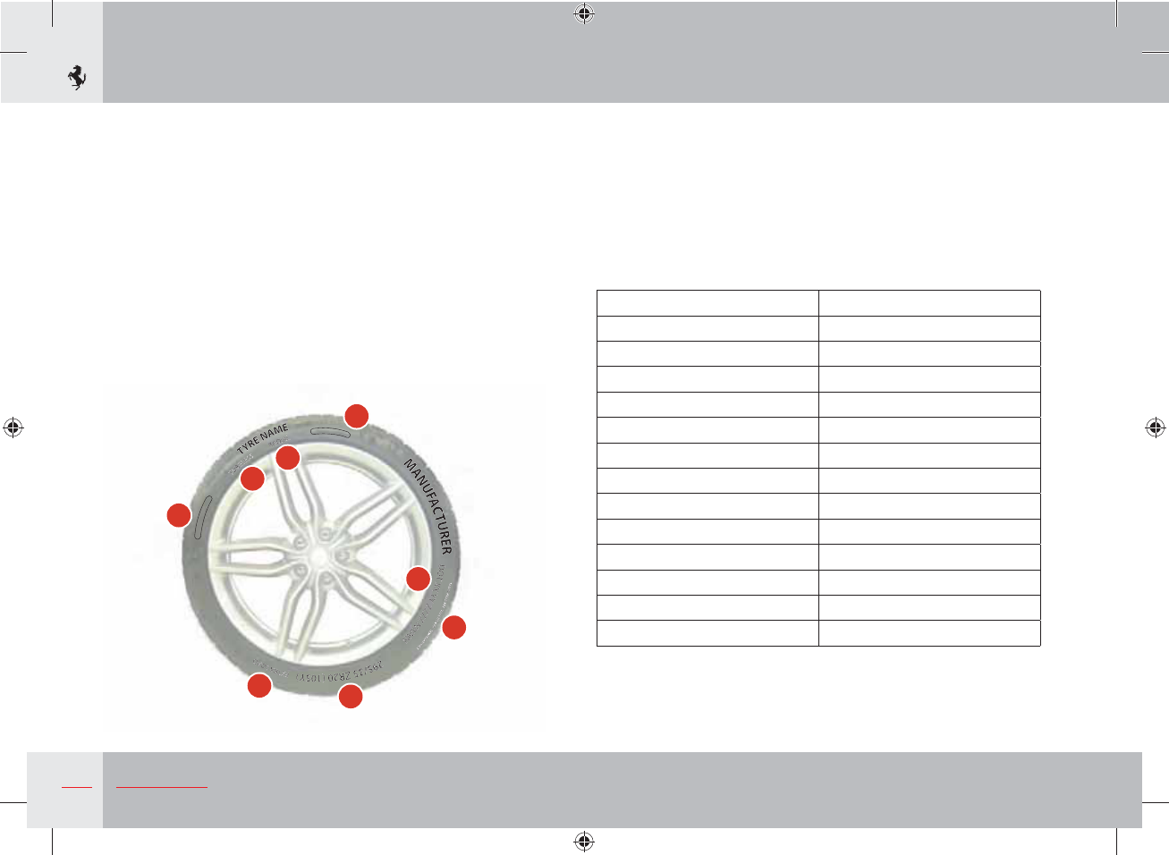
Explanation of codes and wording on tyre side walls
1) Tyre size and characteristics
Example: 245/35 ZR 20 (105Y)
245 = Nominal width (distance in mm from side to side)
35 = Height/width ratio as a percentage
ZR = Radial tyre that can withstand speeds above 240 km/h.
Combined with the specific load and speed code (in brackets), this
indicates a tyre that can withstand speeds above 300 km/h.
20 = Rim diameter in inches
M
A
X
P
R
E
S
S
3
4
0
K
P
A
(
5
0
P
S
I
)
M
A
X
L
O
A
D
9
2
5
K
G
(
2
0
3
9
L
B
S
)
C
A
N
A
D
A
A
N
D
U
.
S
.
C
O
D
E
S
O
N
L
Y
+
2
S
T
E
E
L
+
1
P
O
L
Y
A
M
I
D
E
T
R
E
A
D
P
L
I
E
S
:
1
P
O
L
Y
E
S
T
E
R
S
I
D
E
W
A
L
L
P
L
Y
4
P
O
L
Y
E
S
T
E
R
1
2
3
4
5
6
7
8
105 = Load index: numerical code associated with the maximum
load permissible on the tyre at a given pressure, at the speed
corresponding to the relative index. The maximum load permissible
is indicated in kg and pounds in the wording (3).
Y = Speed index
This indicates the maximum speed at which the tyre can withstand
the load indicated in the load index.
Speed indexes (ECE-UN 30) are shown in the table below:
Speed Index Maximum speed (km/h)
M 130
N 140
P 150
Q 160
R 170
S 180
T 190
U 200
H 210
V 240
W 270
Y 300
ZR (... Y) > 300
The speed index Y, shown in brackets and associated with the
abbreviation ZR, indicates a tyre that can withstand speeds above
300 km/h.
33
General
1
2) EXTRA LOAD: tyre with a high load capacity
3) Maximum load permissible, indicated in kg and pounds, and
maximum inflation pressure permissible, indicated in kPa and psi.
4) TUBELESS: the tyre has no air chamber
5) RADIAL: radial tyre
6) Details of materials used to construct the tread and tyre side
wall.
7) DOT XX YY ZZ NNNN
DOT (Department Of Transportation) specifications: marking
relative to US regulations, with information on the manufacturer,
production site, tyre type and size. The last four digits, in a box,
indicate the date of manufacture: 1011 means that the tyre was
manufactured in the 10th week of 2011.
Warning
The Ferrari Service Network is suitably equipped to replace
tyres, and to determine whether a tyre is safe for use. Only have
the tyres replaced by the Ferrari Service Network, which has
all the equipment necessary to prevent the risk of damage to
the sensor inside the wheel rim, if installed (on vehicles with
the TPMS tyre pressure and temperature monitoring system),
caused by an inappropriately performed procedures.
8) Uniform Tire Quality Grading: standard, defined by the US
Department of Transportation, that classifies tyre performance in
terms of treadwear, traction and temperature resistance.
For further information on tyres, see page 258.
34 General
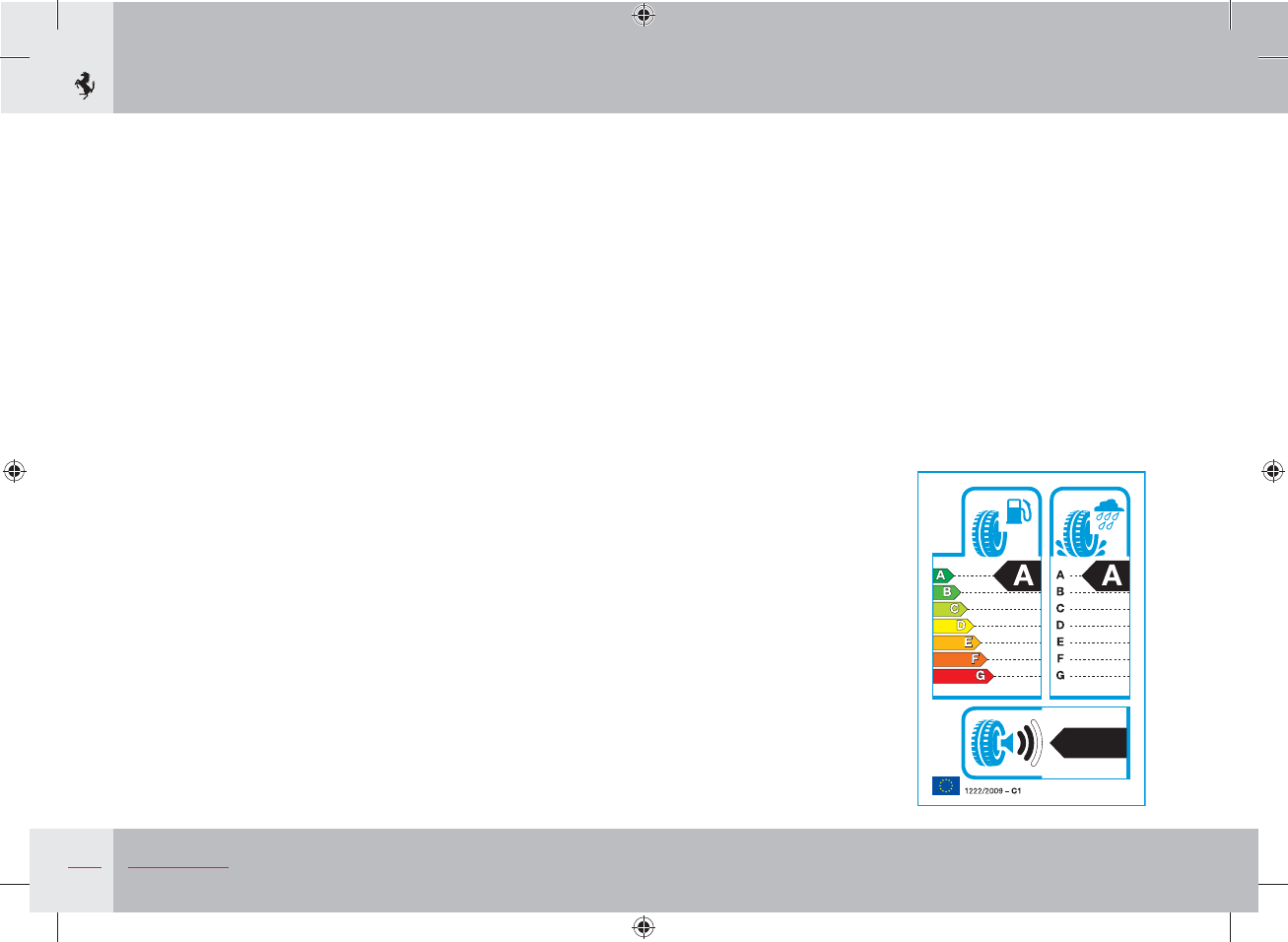
Regulation no. 1222/2009/EC (applies to EU countries only)
Regulation no. 1222/2009/EC states that all tyres sold in EU
countries produced after 1 July 2012 must bear a label (as
shown in the bottom right) containing important information on
performance.
The aim of the regulation is to provide consumers with more
information on safety (wet grip) and environmental (rolling
resistance and external rolling noise) issues in order to promote the
use of safer, quieter and more efficient tyres.
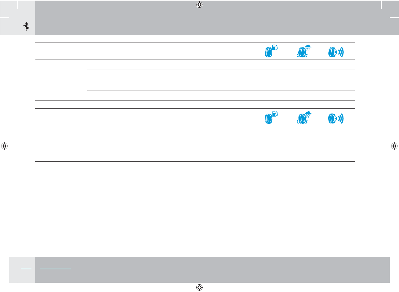
The label provides the following information:
Fuel consumption
The fuel consumption of a vehicle is influenced by the tyre rolling
resistance. There is a scale with 7 levels, from A to G, on the left of
the label where “A” indicates the best tyre class for reducing fuel
consumption with lower rolling resistance.
Wet grip
On the right of the label, there is a scale for tyre performance
when braking on wet roads. Measurements are taken under test
conditions defined in the European Regulation. The scale has
7 levels, from A to G, where “A” indicates the maximum wet grip.
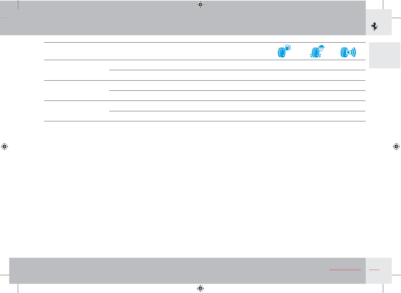
External rolling noise
The bottom of the label indicates the external noise level of the
tyre. The external noise level is measured in decibels (dB) and is
divided into 3 categories based on the new, stricter European levels
of external tyre noise which will be introduced by 2016.
1 black sound wave: 3 dB below future European limit.
2 black sound waves: complies with future European limit.
3 black sound waves: complies with current European limit.
72 dB
35
General
1
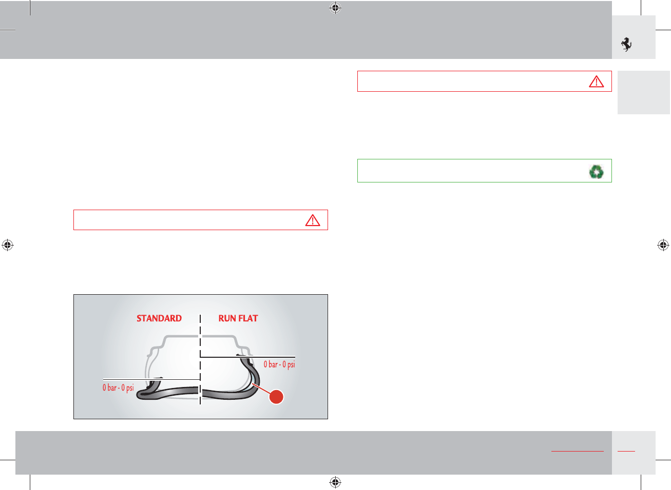
Run Flat tyres (optional)
The vehicle can be fitted with “Run flat” tyres, if required. This type
of tyre has a reinforced side A which allows the vehicle to continue
travelling at moderate speed (80 km/h), even after a puncture, for a
specific distance (100 km).
When the instrument panel receives the “tyre puncture”
information from the tyre pressure monitoring ECU, it calculates
the residual tyre life and displays a warning in the dedicated area of
the TFT display after 50 km.
After 100 km, a message warning the driver to stop the vehicle will
be displayed (for further information, see the “Tyre pressure and
temperature monitoring system” paragraph on page 71).
Warning
Observing the recommended wheel alignment values is essential
in order to obtain the best performance and the longest life of
these tyres.
Warning
If you are going to use standard tyres on a vehicle that was
originally equipped with “Run Flat” tyres, you must contact
the Ferrari Service Network to have the dashboard
reprogrammed and prevent warning messages being displayed
on the left TFT display.
Environment
Maintaining correct tyre pressure helps to improve tyre rolling
and reduce fuel consumption.
"
36 General
Refilling
Parts to be refilled Quantity
Complies with
approval: Recommended by FERRARI Rif.
pag.
Engine Total system capacity 13 l Engine Oil
SAE
1)
5W-40 SHELL HELIX Ultra 5W-40 253
Oil level between Min. and
Max. 1,3 l
Oil consumption 1,0 ÷ 2,0 l/1.000 km
Gearbox and differential 3,5 l Transmission fluid
SAE 1) 75W-90 SHELL SPIRAX S5 ATE 255
Clutch system and hydraulic controls 7,75 l DCT-F3 SHELL DCT-F3
Braking system 1,1 l DOT4
2)
SHELL BRAKE AND
CLUTCH Ultra 257
Cooling circuit 21 l Anti-freeze coolant pre-
diluited GLYCOSHELL LONGLIFE
al 50% + KEMETYL CARIX
Premium G30 Longlife al 50%
255
Hydraulic power steering system 1,5 l CHF 11S or equivalent Pentosin CHF 11S 256
Steering box 100 g CHF 11S or equivalent Pentosin CHF 11S -
Fuel tank 78 l Unleaded petrol
(at least 95 R.O.N.
3)
)
90
Reserve 20 l
RHT system Total system capacity 0,4 l CHF 11S or equivalent Pentosin CHF 11S -
Oil level between Min. and
Max. 65 ml
Air conditioning
and heating system Compressor 165 cc PAG ISO 46 -
Coolant 470 ± 20 g R 134 A DELPHI RL 488
(R 134 A) -
Windscreen washer/headlight washer fluid tank 6 l Mixture of water and
glass cleaner 258
37
General
1
1) SAE - Viscosity class: example SAE 5W - 40
5W = viscosity specification for low temperatures (winter)
40 = viscosity specification for high temperatures
2) DOT - Designation of brake fluid: denote a particular mixture
of chemicals imparting specified ranges of boiling point.
3) R.O.N. - Octane number: is a standard measure of the
antiknock performance of motor fuel.
Instructions for vehicle refuelling
Warning
Only fill the vehicle with unleaded petrol.
Using unleaded petrol is fundamentally important to ensure
that the catalytic converters of the vehicle's exhaust system work
properly.
Warning
Never put leaded petrol in the fuel tank, not even in
emergencies: fuel deposits could irreparably damage the
catalytic converters.
Environment
Inefficient catalytic converters produce harmful emissions at the
exhaust and pollute the environment.
For optimal engine performance and efficiency, Ferrari strongly
recommends using unleaded petrol with an octane rating (R.O.N.)
of 98.
As unleaded petrol with a 98 R.O.N. is not always available, the
engine can however be used with unleaded petrol with an octane
rating of not below 95 R.O.N. In this case, the engine control
system will appropriately adjust calibrations to allow the vehicle to
function correctly but performance will be diminished.
Warning
The use of unleaded petrol with a R.O.N. below 95 can cause
malfunctioning and is not recommended.
Important note
This vehicle is suitable for use with unleaded fuel with a
maximum of 10% ethanol (E10).
Warning
The use of fuels with 10% to 25% ethanol can lead to
malfunctioning.
The use of fuels with over 25% ethanol can cause permanent
damage to the engine fuel system.
See page 90 for further information.

1. General
2. Safety
3. About your Vehicle
4. Advice for Emergency Situations
5. Care of the vehicle
6. Glossary
7. Table of Contents
40 Safety
Ferrari has designed and built a high performance vehicle.
In order to take advantage of the safety systems described below, it
is essential to comply with the indicated regulations.
Special recommendations
This vehicle has been built to comply with homologation, personal
safety and environmental regulations.
These high safety standards must always be accompanied by careful
and cautious behaviour of the driver.
Particular attention must be paid to:
s/VERHEATEDCOMPONENTS(IGHTEMPERATURESDEVELOPINTHE
engine compartment in proximity of the exhaust system. Do not
park the vehicle on paper, grass, dry leaves or other flammable
materials. They could catch fire if they come into contact with
hot parts of the exhaust system. Do not fit other heat shields or
remove those fitted on the exhaust system. Do not let flammable
substances come into contact with the exhaust system.
s-OVINGPARTSOFTHEVEHICLESUCHASBELTSFANSETC4HEYMUST
always be adequately protected. Do not remove the guards or
operate on the moving parts without taking due precautions.
s)NSTALLATIONSUNDERPRESSURESUCHASBRAKINGSYSTEMAIR
conditioning system, cooling system and lubrication system may
create pressures inside them. Do not perform any operation which
may cause gas or liquids to spill out with the risk of injury to
persons and damage to things.
Emissions
Warning
s4HEEXHAUSTGASGENERATEDBYTHERUNNINGENGINEMAYBE
hazardous, especially when in closed spaces. As well as
consuming oxygen, the engine discharges carbon dioxide,
carbon oxide and other toxic gases.
s&UELISHIGHLYINmAMMABLEANDEMITSVAPOURSWHICHMAYBE
noxious if inhaled.
Do not use naked flames or create sparks near the open fuel
tank or in any other condition where fuel comes into contact
with air.
Lubricants
Warning
s4HEOILSUSEDMAYALSOBEmAMMABLETAKETHESAME
precautions as those adopted for fuel.
Flammable fluids
Warning
s4HEmUIDINTHEBATTERYISPOISONOUSANDCORROSIVE$ONOTLET
it spill out and come into contact with the skin, eyes or objects.
Do not use naked flames or create sparks near the battery.
Fuel inertia switch
s3EEPAGE
41
2
Safety
Warning
Seat belts must be worn at all times and must be properly
fastened and adjusted!
Correct use of the seat belts can significantly reduce the risk
and severity of injury if an accident occurs or if the vehicle
overturns.
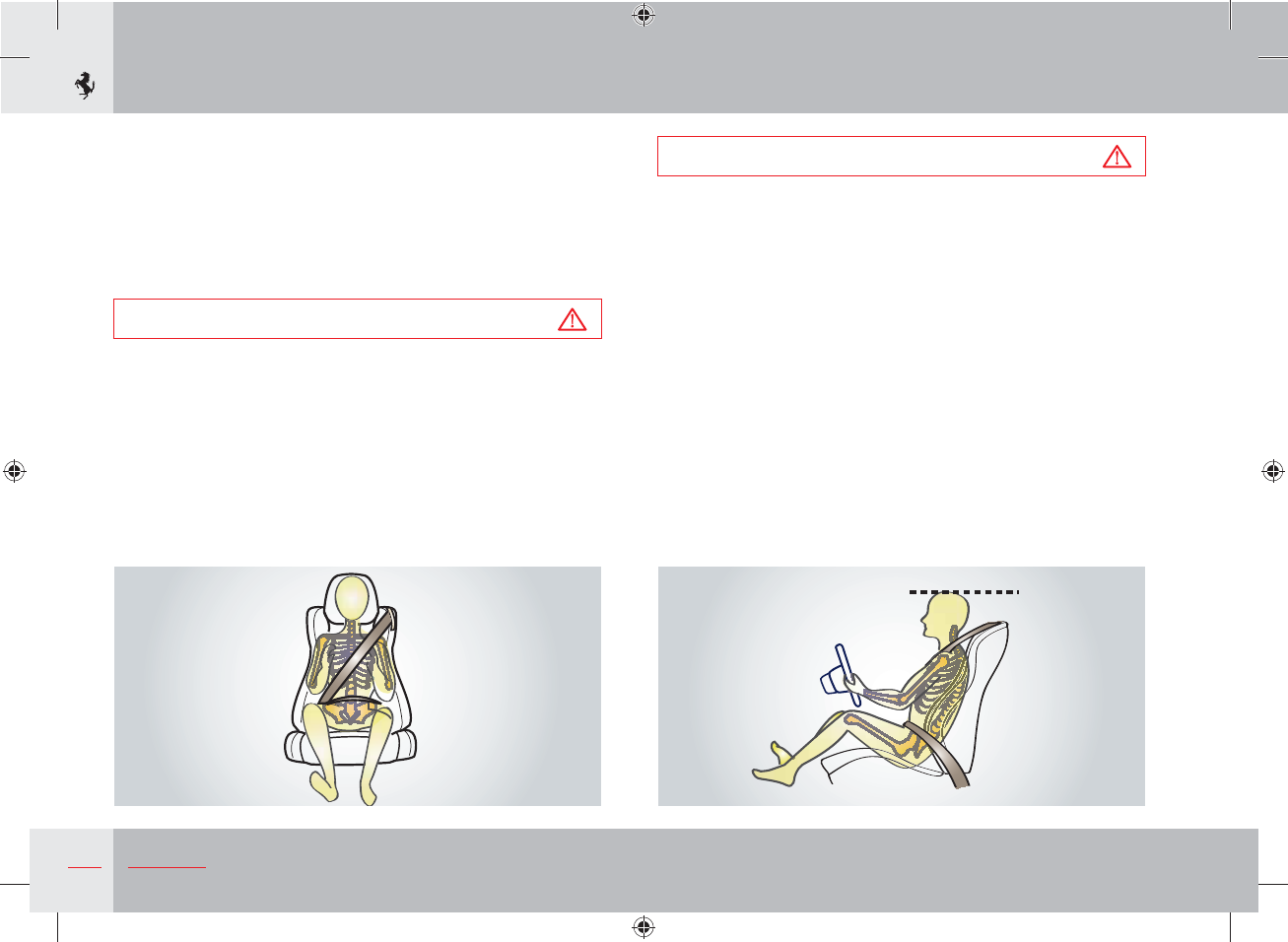
Warning
For an effective restraining action, the seat belt must be fastened
correctly with the seat backrest in the upright position.
The seat belt is fastened correctly when the upper part of the
belt crosses the centre of the shoulder (not the neck) and the
abdominal section is fitted over the hips (not the abdomen).
Make sure that the belt is not twisted and that it passes closely
over your body; if not, in the event of a head-on collision, it may
move and cause injury to the abdomen.
Avoid wearing bulky clothing that may interfere with the proper
operation of the seat belts.
Warning
To increase driving safety, it is advisable to position the headrest
so that its top is in line with the top of the head.
Warning
Each seat belt has been designed to protect only one occupant.
If more than one person uses the same seat belt, the risk of
injury in the event of an accident is increased.
Do not sit babies, small children or other persons on your lap.
If there is a collision, the weight of an adult may cause the
child to be crushed by the seat belt causing severe or even fatal
injuries.
Pregnant women
The best protection for pregnant women and their unborn babies
is to wear the seat belt correctly. This significantly reduces the risk
of injury to the baby. As a result, pregnant women must always
wear a seat belt unless specifically directed otherwise by a medical
practitioner. The upper part of the diagonal section of the seat belt
must lie snug on the front of the shoulder, pass between the breasts
down to the abdomen. The horizontal strap must sit snugly and as
far below the abdomen as possible.
42 Safety
Passive safety
The passive safety system has been designed to reduce the risk and
severity of injury if an accident occurs.
The vehicle is equipped with the following seat belts:
1. 3-point driver seat belt with pretensioner and load limiter
(see page 44);
2. 3-point front passenger seat belt with pretensioner and load
limiter (see page 44);
and, only when rear seats are provided:
3. 3-point seat belt in the seat behind the front passenger with
pretensioner and load limiting device (see page 47);
4. 3-point seat belt in the seat behind the driver with load limiting
device (see page 47)
Warning
Auxiliary safety systems are not a substitute for seat belts. All
occupants must always wear a seat belt. Correct use of the
seat belts combined with use of the auxiliary safety systems
provides optimal protection to the occupants in various types of
collisions.
The vehicle also has the following auxiliary occupant protection
system components (see page 56 “Auxiliary occupant protection
systems”):
5. driver side front airbag (see page 59 for functioning logic);
6. passenger side front airbag (see page 59 for functioning logic);
7. driver side lateral airbag (head bag)
(see page 62 for functioning logic);
8. passenger side lateral airbag (head bag)
(see page 62 for functioning logic);
9. active roll bars (for operating functions see page 65);
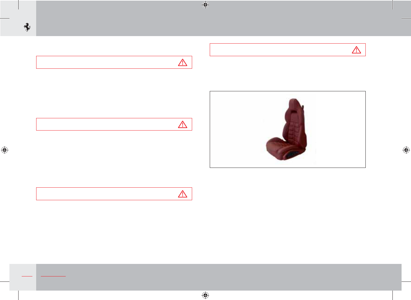
10. seats (see page 193);
11. deformable bo dy;
12. occupant protection system ECU;
13. ECU auxiliary sensors;
14. instrument panel warning light (see page 63);
15. inertia switch.
Only in the presence of rear seats (see also page 50 “Child safety”):
16. a child seat lower anchorage system in the seat behind the front
passenger;
17. a child seat lower anchorage system in the seat behind the
driver.
The vehicle does not have upper anchorage systems for the
installation of child seats.
Warning
The protective action of the airbags is always integrated with
the seat belts and the pretensioners. The compulsory use of the
seat belt is provided by the national regulations (in Italy, for
example, by the Codice della Strada, i.e. Traffic Regulations).
43
2
Safety
Deformable body
The deformable body absorbs shock and distributes it over the
entire structure of the vehicle allowing progressive deceleration.
The passenger compartment structure, on the other hand, has been
designed to provide maximum resistance without undergoing
deformation in order to guarantee a protective survival cell for the
occupants.
Active safety
The aim of the active safety system is to reduce the risk of accidents
and injury severity.
The vehicle has been designed to provide a high level of safety for
whoever uses it. The following systems are specific active safety
components:
sBRAKINGSYSTEM
sAIRCONDITIONINGANDHEATINGSYSTEM
sEXTERNALLIGHTS
sBUZZERANDWARNINGLIGHTSmASHING
The braking system includes the mechanical brake system and the
electronic stability and traction control system (ABS and EBD):
this is designed to prevent the wheels from locking and to provide
good handling and stability.
In some situations, fast acceleration is important to get out of
dangerous situations. However, always use the accelerator with
extreme caution. During acceleration of the driving wheels, the anti-
skid system may help you in certain dangerous situations.
The air conditioning and heating system in the passenger
compartment can add to driving comfort and keep you alert so that
you can react quickly when necessary.
It is very important to be able to see the road clearly and be seen
and external lights must be turned on when the conditions so
require.
44 Safety
Seat belts
Statistics show that when used correctly, seat belts reduce the risk
of injury in various types of crashes including the risk of ejection
from the vehicle and impact with the interior of the vehicle.
If unfastened, the seat belts do not provide any type of protection.
Before every trip, always make sure that all occupants are wearing
their seat belts.
Warning
Seat belts must be worn at all times and must be properly
fastened and adjusted!
Correct use of the seat belts can reduce the risk of serious injury
in the event of an accident or if the vehicle overturns.
Warning
For an effective restraining action, the seat belt must be fastened
correctly with the seat backrest in the upright position.
The seat belt is fastened correctly when the upper part of the
belt crosses the centre of the shoulder (not the neck) and the
abdominal section is fitted over the hips (not the abdomen).
Make sure it is not twisted and that it passes closely over your
body; if not, in the event of a head-on collision, it may move
and cause injury to the abdomen.
Avoid wearing bulky clothing that may interfere with the proper
operation of the seat belts.
The seat belts for the front seats have a lap-shoulder belt with
an automatic emergency-locking retractor and are fitted with a
pyrotechnic-powered pretensioner and an automatic system that
reduces the force applied to the occupant.
45
2
Safety
The seat belts for the rear seats have a lap-shoulder belt with
an automatic emergency-locking retractor and are fitted with a
pyrotechnic-powered pretensioner and an automatic system that
reduces the force applied to the occupant.
Warning
To increase driving safety, it is advisable to position the headrest
so that its top is in line with the top of the head.
Warning
Do not let the seat belts come into contact with cutting edges.
They may get damaged and may consequently break in the
event of a collision.
Warning
Each seat belt has been designed to protect only one occupant.
If more than one person uses the same seat belt, the risk of
injury in the event of an accident is increased.
The seat belt must never be passed around a baby, child or
other person sitting on a passenger's lap.
Do not sit babies, small children or other persons on your lap.
If there is a collision, the weight of an adult may cause the
child to be crushed by the seat belt causing severe or even fatal
injuries.
Warning
Do not attach or pin anything onto the seat belts: they may get
damaged and may consequently break in the event of a collision.
Warning
If a seat belt has come into contact with cutting edges or
was somehow perforated, we recommend that you have it
immediately replaced by the Ferrari Service Network.
Warning
Periodically check the condition of the seat belts. If the belt
shows signs of wear, it must be checked by a qualified person
and replaced if necessary. Contact the Ferrari Service
Network immediately.
46 Safety
How to fasten seat belts
Warning
For an effective restraining action, the seat belt must be fastened
correctly with the seat backrest in the upright position.
The seat belt is fastened correctly when the upper part of the
belt crosses the centre of the shoulder (not the neck) and the
abdominal section is fitted over the hips (not the abdomen).
Make sure it is not twisted and that it passes closely over your
body; if not, in the event of a head-on collision, it may move
and cause injury to the abdomen.
Avoid wearing bulky clothing that may interfere with the proper
operation of the seat belts.
Once you have adjusted the seat correctly (see page 193);
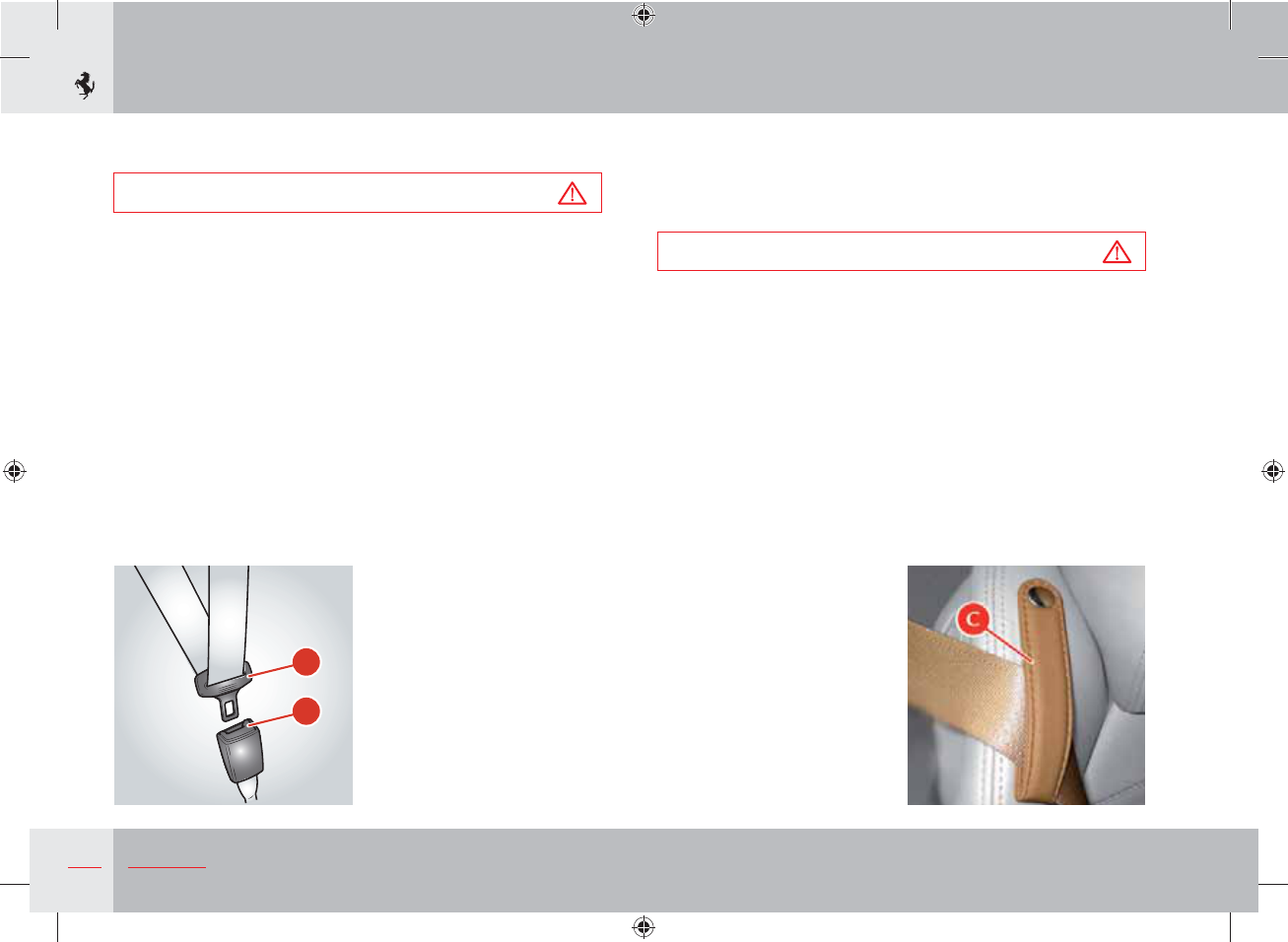
s'RIPTHELATCHPLATEA, slowly pull the belt and insert the latch
plate into the buckle B (if the belt locks while you are pulling it
out, let it wind back briefly and pull it out again without jerking).
s-AKESURETHATITHASCLICKEDINTOTHELOCKEDPOSITIONHOLDTHE
belt and pull it to check that the latch plate has been inserted
correctly.
s0OSITIONTHESEATBELTCORRECTLY
Warning
To position the front seat belt correctly, make sure that it passes
through the loop C, as shown in the figure.
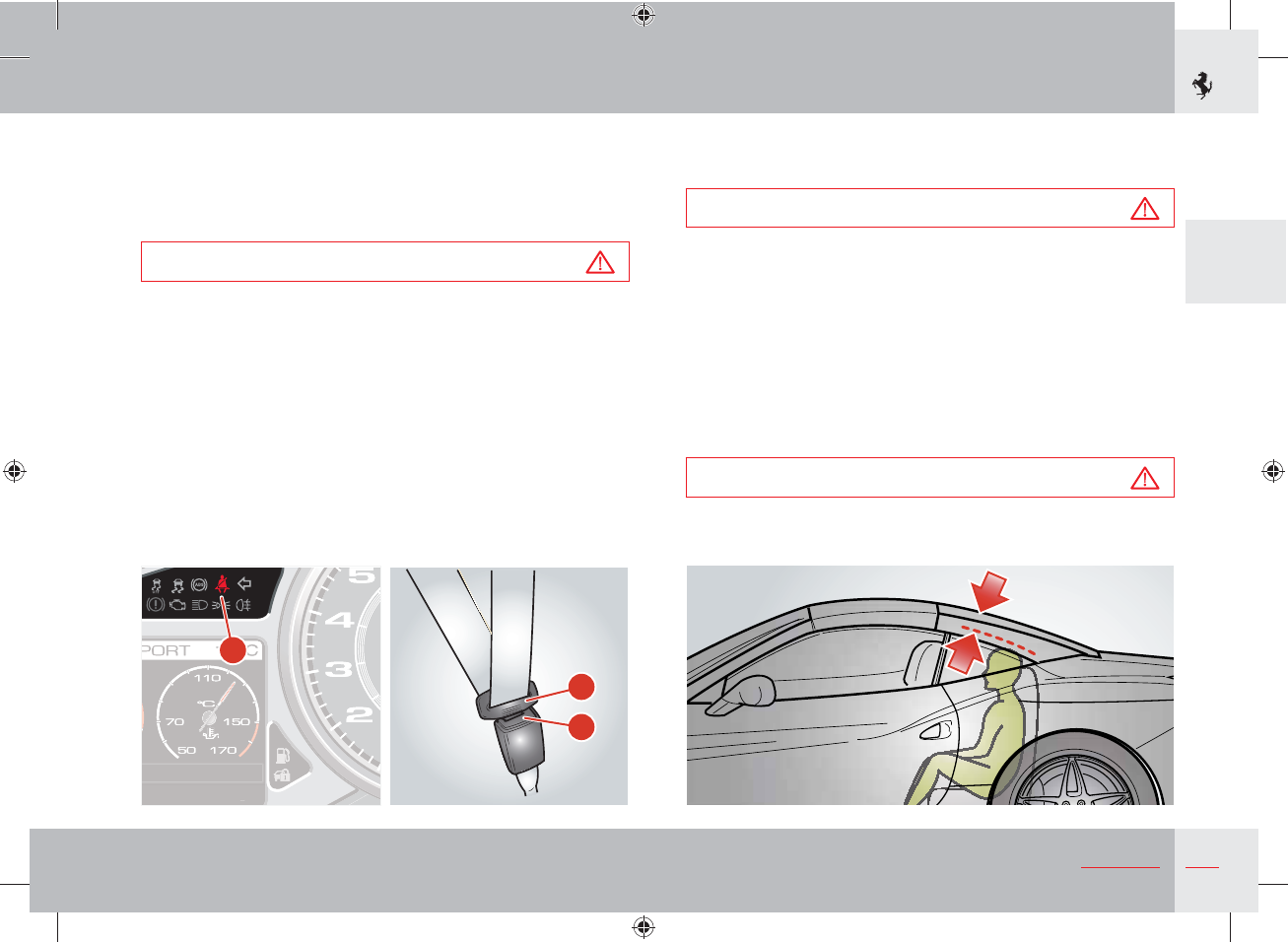
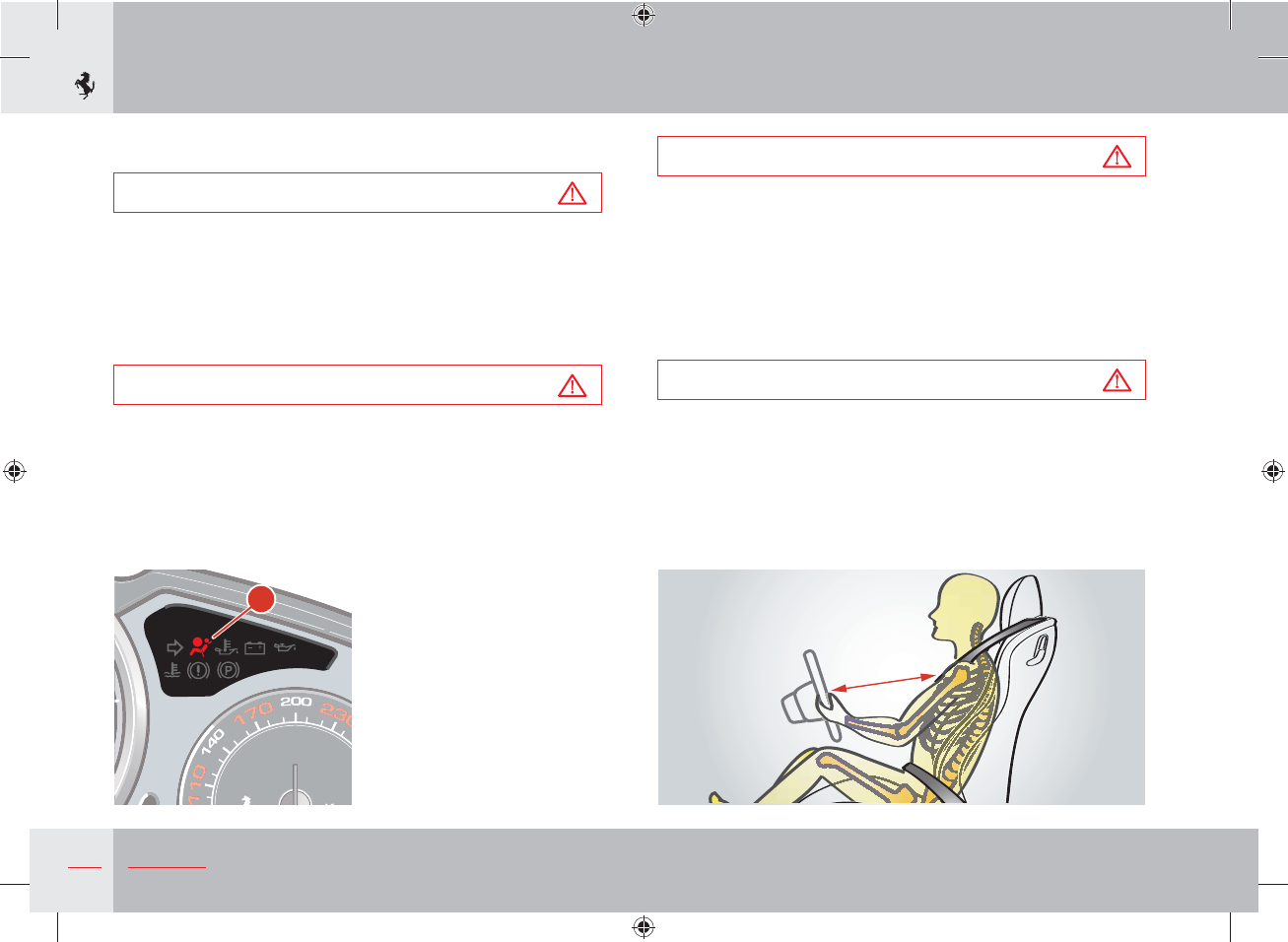
If the driver’s seat belt is not fastened, when you turn the ignition
key to position II, the warning light D on the instrument panel
lights up and remains lit until the seat belt is fastened.
55 seconds after a speed of 10 km/h is exceeded, a buzzer sounds
warning the driver that the seat belt is not fastened.
When a speed of 20 km/h is exceeded, the buzzer activates
immediately and stops after 90 seconds.
"
#
47
2
Safety
This acoustic signal is emitted only once, even if the vehicle speed
goes above and below the above mentioned limits. It is repeated
(when the vehicle speed is in the indicated ranges) only if the seat
belt is fastened and unfastened again or, in any case, every time the
engine is turned off and then on.
Warning
Each seat belt has been designed to protect only one occupant.
If more than one person uses the same seat belt, the risk of
injury in the event of an accident is increased.
The seat belt must never be passed around a baby, child or
other person sitting on a passenger's lap.
Do not sit babies, small children or other persons on your lap.
If there is a collision, the weight of an adult may cause the child to
be crushed by the seat belt causing severe or even fatal injuries.
Unfastening the seat belts
s0USHTHERELEASEBUTTONE.
s'UIDETHELATCHPLATEA back to its rest position.
Use of rear seat belts
Warning
Only persons who are less than 1.50 m tall may travel in the
rear seats.
The minimum distance between the head of the rear passenger
when seated correctly and the rear window must be at least
2.5 cm.
Any taller person travelling in the rear seat risks serious injury in
the event of an accident.
Any taller person travelling in the rear seat risks serious injury if
the retractable hard top is opened or closed.
Warning
The retractable hard top MUST only be operated when no
persons and/or children are occupying the rear seats.
A
E
D
48 Safety
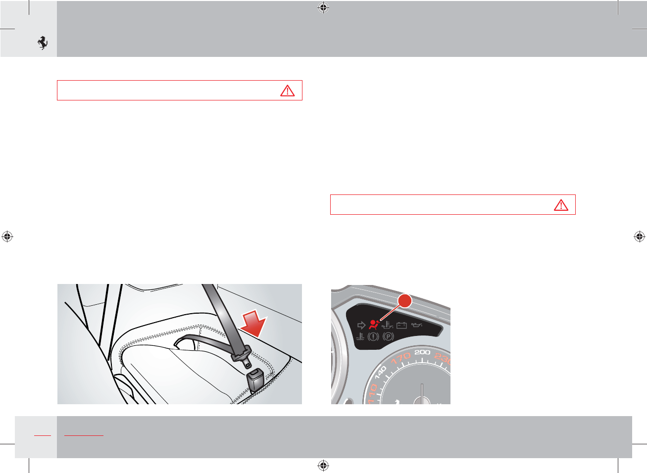
The rear seat belts must be fastened as shown in the diagram.
Warning
Remember that, in the event of a violent impact, passengers
in the rear seats who are not wearing seat belts are not only
subject to personal injuries (they can be projected forward,
hit the windscreen and be thrown out of the vehicle) but also
constitute a danger to the passengers in the front seats.
Pretensioners
The seat belts for the front seats are fitted with pyrotechnic-
powered pretensioners. The pretensioner is activated by the airbag
ECU when there is a sufficiently severe head-on collision (impact
direction between 11 and 1 o'clock p.m.) or a sufficiently severe
side collision. The pretensioner is also activated when there is a
sufficiently severe rear collision or a roll-over. The belt will rewind
a few centimetres just before the restraining action begins, thereby
improving the fitting across the occupant's body.
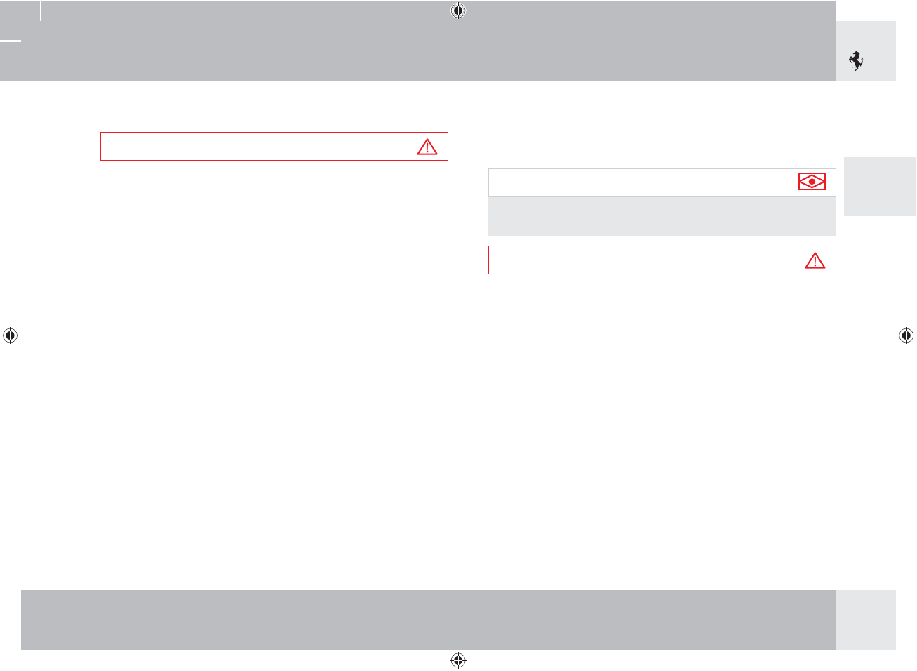
Activation of a pretensioner is signalled by the illumination of the
warning light A on the instrument panel.
Warning
Pretensioners that have been activated will no longer function
and may not be repaired under any circumstances. Contact the
Ferrari Service Network for replacement.
A
49
2
Safety
When a pretensioner is activated, a small amount of smoke is
released. This smoke is not harmful.
Warning
Activation of the pretensioners only depends on the status of the
seat belts and is not affected by the occupants' presence.
If the seat belt is not fastened, the pretensioner will not activate,
even if the seat is occupied.
The seat belts for the front seats and any rear seats are fitted with a
load limiting device. The load limiting device is located in the belt
winder and allows controlled release of the belt during a collision
thereby limiting the impact that the belt has on the occupant's
body.
Maintenance of seat belts and pretensioners
s&OLLOWINGASERIOUSCOLLISIONREPLACETHESEATBELTSTHATWEREWORN
at the time even if they do not appear to be damaged.
s0ERIODICALLYCHECKTHATTHESCREWSONTHEANCHORPOINTSARETIGHT
and that the seat belt is in perfect condition and slides smoothly.
s4HESEATBELTMUSTBEKEPTCLEANTHEPRESENCEOFANYDIRTCOULD
prevent the seat belt retractor from working properly.
s4OCLEANTHESEATBELTWASHITBYHANDWITHMILDSOAPANDWATER
and let it dry. Do not use strong detergents, bleach or aggressive
solvents, as they can weaken the fibres.
Make sure the retractors do not get wet: proper functioning is
only ensured if they are kept dry.
s4HEPRETENSIONERREQUIRESNOMAINTENANCEORLUBRICATION
If immersed in water or mud, it must be replaced.
s0RETENSIONERSMUSTBEREPLACEDATREGULARINTERVALSASINDICATEDIN
the “Warranty Booklet”.
Important note
All work on any part of this safety system must be performed by
the Ferrari Service Network.
Warning
Removing or making modifications of any kind to the seat belts,
belt retractors and pretensioners is not allowed.
Maintenance work involving strong impacts, vibrations or
heating of the pretensioner area may activate them; vibrations
caused by road bumps will not have this effect.
50 Safety
Child safety
Warning
Never leave children ALONE and/or unattended in the vehicle
since this may constitute a danger to themselves and others.
In many countries, the transportation in vehicles of children and
infants is governed by specific legislation.
Drivers are obliged to comply with applicable regulations.
Warning
If we use a risk assessment matrix that combines the likelihood
of an event occurring and its consequences, we can see that a
child in a child seat on the front seat presents a serious risk and
the responsibility of the driver is therefore high. All possible
precautions should be taken.
Even in latest generation vehicles, statistics show that the rear
seats are the safest position for transporting babies and children.
Warning
Drive slowly and pay maximum care and attention when
transporting children. Sudden acceleration caused by sports-
style driving may be dangerous for children even if no collision
occurs.
Warning
The instructions in this Owner’s Manual ONLY apply to the
seats shown in the figures below.
51
2
Safety
Warning
Do not transport young children in rearward facing child
restraint systems on the front passenger seat.
Because of their size, children are at greater risk than adults.
Suitable child restraint or safety systems must therefore be used
and seat belts should only be used to secure the child seats.
All minors whose physical characteristics (i.e. height, weight) fall
within the legal limits in force in each country must be protected
by approved restraint or safety systems (e.g. child seats, cradles,
cushions).
You are therefore advised to ALWAYS use homologated child
restraint systems that bear the proper test marking. Child
seats approved according to the ECE-R 44 standard bear this
alphanumeric code (a letter “E” in a circle with the approval
number underneath) followed by the name of the group (e.g.
Group 2).
Warning
Incorrect fastening of a child restraint system increases the risk
of injury to the child if an accident occurs.
The seat belts on a vehicle have been designed and tested to
protect persons who are over 1.50 m tall.
To properly protect children outside these limits, specific restraint
systems with dedicated belts or accessories capable of adapting the
child’s position to the vehicle seat belts must be fitted.
Warning
For installation and use (how to secure the child to the restraint
system) of child restraint systems, follow the instructions that
the manufacturer of the devices is obliged to provide.
Warning
Carefully follow the instructions provided with the child
seat: keep them in the vehicle together with the documents
and this manual. Do not use second-hand child seats with no
instructions.
Warning
Follow the instructions given by the child restraint system
manufacturer when choosing, installing, positioning (forward/
rear facing) and using the restraint system since failure to do so
may compromise its protective action.
52 Safety
Warning
Always check the seat belts have been securely fastened by
pulling on the seat belt.
Warning
After an accident, have all the parts of the child restraint system
and vehicle seat belt system checked and replace them if
necessary.
Any work must be performed at the Ferrari Service Network.
Children must always be transported in restraint systems that are
suitable for their size.
Before choosing a child restraint system, always check that:
- it is homologated. The homologation standard is ECE-R 44
(a letter “E” in a circle with the approval number underneath)
followed by the name of the group (e.g. Group 2);
- it is suitable for the height and weight of the child to be
transported (CAREFULLY FOLLOW the instructions in the child
restraint system use and maintenance manual);
- it can be securely installed in the vehicle in compliance with the
child restraint system manufacturer's instructions;
- the use and installation instructions are easy to understand.
Warning
If violent braking or a collision occurs, children who are not in
a restraint system can be thrown against the dashboard or the
windscreen: this may lead to serious or even fatal injury to the
child.
Warning
Never allow children to travel sitting in the lap of an adult.
If there is a collision, the adult's weight may crush the child
against the seat belt, the dashboard or the back of the front seat:
this may lead to serious or even fatal injury to the child.
Important note
NO modifications MUST be made to the seat belts and child
restraint systems: any modifications may seriously jeopardise the
safety of the child restraint system.
Front passenger seat
The front passenger seat does not have ISOFIX hooks for child
restraint systems.
Secure the child restraint system to the vehicle seat using the seat
belt and make sure you have activated the automatic belt winding
locking system before installing the child seat in the vehicle.
To activate the automatic belt winding locking system, pull the
seat belt until the belt completely unwinds. At this point, the belt
retractor will only allow the seat belt to rewind.
53
2
Safety
The fact that the belt cannot be pulled out confirms that the belt
locking system has been activated.
To deactivate the locking system, unfasten the seat belt in order to
allow it to rewind completely.
Warning
Each time the belt is used to fasten a normal occupant,
the automatic belt winding locking system will have to be
deactivated.
Warning
ALWAYS COMPLY with the legal requirements in force in your
own country: restrictions on the use of seat belts are applied
according to age (up to 12 years old) and height (up to 1.50 m).
Important note
For child restraint systems that can be installed on the front
passenger seat with 3-point seat belts, see TAB. 1 on page 77.
54 Safety
Rear seats
Statistics show that the rear seats are the safest position for
transporting babies and children.
Warning
Before installing a child restraint system on the rear seats, the
corresponding front seat must first be positioned as far forward
as possible with the backrest as upright as possible.
Warning
The retractable hard top MUST only be operated when no
persons and/or children are occupying the rear seats.
Warning
Before operating the retractable hard top, make sure that the
backrest of the child restraint system is set to its minimum
height.
Warning
If violent braking or a collision occurs, children who are not
travelling in a restraint system can be thrown against the
dashboard, windscreen or front seats: this may lead to serious or
even fatal injury to the child.
Warning
Never allow children to travel sitting in the lap of an adult.
If there is a collision, the adult's weight may crush the child
against the seat belt, the dashboard or the back of the front seat:
this may lead to serious or even fatal injury to the child
To transport a child on the rear seats, use the seat belts to secure
the child restraint system to the vehicle seat and make sure you
have activated the automatic belt winding locking system before
installing the child seat in the vehicle.
To activate the automatic belt winding locking system, pull the
seat belt until the belt completely unwinds. At this point, the belt
retractor will only allow the seat belt to rewind.
The fact that the belt cannot be pulled out confirms that the belt
locking system has been activated.
To deactivate the locking system, unfasten the seat belt in order to
allow it to rewind completely.
Warning
Each time the belt is used to fasten a normal occupant,
the automatic belt winding locking system will have to be
deactivated.
55
2
Safety
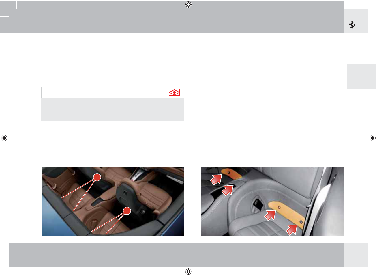
A
A
Both rear seats are fitted with an ISOFIX fastening system
consisting of two lower anchor points (marked A in the figure).
The lower anchor points A are located between the seat cushion
and the back of the rear seats under the special leather cover. The
anchor points are marked with a special symbol so that they can be
easily found.
The vehicle has no upper anchorage systems.
Important note
For child restraint systems that can be installed on the rear seats
with 3-point seat belts and the ISOFIX system respectively, see
TAB 2., TAB 3. and TAB 4. on pages 78-79.
56 Safety
8. Rear seat passenger seat belt (3-point with automatic system
that reduces the force applied to the occupant).
9. Rear seat passenger seat belt (3-point with automatic system
that reduces the force applied to the occupant).
10. Active roll bars.
11. Electronic Control Unit (ECU).
12. Additional sensors.
13. Instrument panel warning light.
14. Deformable bo dy.
Auxiliary Occupant Protection Systems
(driver and passengers)
Warning
Auxiliary Occupant Protection Systems are not a substitute for
seat belts but increase their efficiency. Correct use of the seat
belts, with the supplementary action of the Auxiliary Occupant
Protection Systems, offers maximum protection in the event of a
head-on collision or vehicle roll-over.
Auxiliary Occupant Protection System components (driver and passengers)
The Auxiliary Occupant Protection System components are:
1. Seat with built-in headrest and belt loop.
2. Dual-stage front driver's airbag.
3. Dual-stage front passenger airbag.
4. Driver's head protection side airbag (head bag).
5. Passenger head protection side airbag (head bag).
6. Driver's seat belt (3-point with pretensioner and an automatic
system that reduces the force applied to the occupant).
7. Front passenger seat belt (3-point with pretensioner and
an automatic system that reduces the force applied to the
occupant).
57
2
Safety
The airbags 2 and 3 have been designed to increase the level of
protection given by the seat belts in the event of a head-on collision
(see page 58).
The airbags 4 and 5 have been designed to increase the level of
protection given by the seat belts in the event of a side collision
and are placed between the occupant’s head and external structures
which could go through the passenger compartment and cause
injury (see page 62).
The roll bars 10 have been designed to help maintain a survival
area in the event of a roll-over (see pages 65-67).
Since it is impossible to gauge vehicle dynamics and movements of
the occupants in an accident, the active roll bars are also activated
as a precautionary measure in the event of:
- sufficiently severe head-on collisions (that activate the front
airbags) if they have caused a cut-out of the fuel supply;
- sufficiently severe side or rear collisions.
Warning
The warning light A (see page 48) comes on when the ignition
key is turned to position II. If no malfunctions are detected, it
goes out after approximately 4 seconds. If the warning light
does not come on, if it remains on or if it comes on while
driving, contact the Ferrari Service Network immediately.
58 Safety
Warning
The driver and the passenger must maintain a distance of at
least 25 cm from the steering wheel and the dashboard.
Always drive with your hands on the rim of the steering wheel
so that in the event of activation, the airbag can deploy without
obstruction.
Driving with your hands on the steering wheel spokes or on the
airbag cover increases the risk of injury for your wrists and arms.
Warning
The front passenger must be seated correctly: never put your
hands, feet or legs on the dashboard since if the front airbag is
activated, it may cause injury to your legs and prevent the airbag
from working properly.
Driver and passenger airbags
Warning
The front airbags do not provide protection in the event of
side-on collisions, some head-on/angular collisions, roll-overs
or subsequent collisions (if there is a second collision once the
airbags have been deployed in an earlier collision). The seat
belts have been designed to reduce the risk of injury in the
event of a roll-over or subsequent collision.
Warning
The front airbags have been designed not to inflate if a minor
collision occurs. The seat belts have been designed to reduce
the risk of injury if a minor collision occurs.
At least 25cm
A
59
2
Safety
Operation
The front airbags are controlled by an ECU which activates them
when there is a sufficiently severe head-on collision (direction of
impact between 11 and 1 o'clock p.m.).
In the event of a collision with an impact force that causes
deceleration that exceeds the value set for the internal sensor, the
ECU will transmit a signal to deploy the airbags. The airbags will
begin to inflate, breaking the cover along the breakage line and will
deploy completely in a few tenths of milliseconds. Once deployed,
they will serve as protection between the driver and/or passenger
and structures that could cause injury.
The airbags deflate immediately afterwards.
Important note
If a head-on collision occurs that causes a cut-out of the
fuel supply, the active roll bars will also be activated as a
precautionary measure.
Warning
The driver and passenger should not carry objects (drink cans
or bottles, pipes, etc.) that may cause injury if the airbags are
activated.
Persons, animals or items must not be placed between the
airbags and the occupant.
Environment
When the system is activated, gases are released in the form
of fumes, together with the gas used for inflating the airbags.
These gases are not harmful.
The driver's airbag has been designed to be deployed according
to the following strategy:
s&ORLOWSEVERITYCRASHESTHEAIRBAGCONTROLUNITWILLNOTDEPLOY
the airbag.
s&ORCRASHESOFHIGHERSEVERITYTHECONTROLUNITWILLDEPLOYTHE
driver airbag in low energy mode.
s&ORCRASHESOFEVENHIGHERSEVERITYTHECONTROLUNITWILLDEPLOY
the driver airbag in high energy mode.
The passenger airbag has been designed to be deployed
according to the following strategy:
s&ORLOWSEVERITYCRASHESTHEAIRBAGCONTROLUNITWILLNOTDEPLOY
the airbag.
s&ORCRASHESOFHIGHERSEVERITYTHECONTROLUNITWILLDEPLOYTHE
passenger airbag in low energy mode.
s&ORCRASHESOFEVENHIGHERSEVERITYTHECONTROLUNITWILLDEPLOY
the passenger airbag in high energy mode.
Warning
Even in vehicles with Advanced Airbag Systems, according to
statistics, the rear seats are the safest position for transporting
babies and children.
Children must always be transported on the rear seats if the
vehicle is equipped with them.
Warning
The driver and passenger must always fasten their seat belts
and sit in an upright position, as far as possible away from
the airbag, in order to have optimal protection in all types of
collision.
60 Safety
Important note
Do not cut or tamper with the connectors of the airbag harness
or on the airbag modules.
Warning
Do not cover the steering wheel and the padded panel on the
dashboard on the passenger’s side with adhesive tape or treat it
in any way.
Warning
Do not place objects above or near the top of the dashboard
and the steering wheel.
In the event that the airbags are deployed, these objects would
be projected into the passenger compartment at a high speed
that would seriously jeopardise the safety of the occupants.
Warning
Do not modify the airbag modules in any way (indicated in
the relevant picture). Do not damage the airbag modules (for
example pinning something onto them or pressing objects
against their covers).
If, for any reason, an airbag cover gets damaged, have the airbag
module immediately checked by the Ferrari Service Network.
Activation of a damaged module could cause serious or fatal
injuries.
Warning
Always keep the backrest of your seat in the upright position
and sit with your back properly resting against it.
Important note
Do not modify the system components or wiring, under any
circumstances.
With the ignition key inserted and in position II, although the
engine is off, the airbags can still be activated when the vehicle is
stationary if it is hit by a moving vehicle.
Remember that if the ignition key is set to 0 none of the safety
devices (airbags or pretensioners) is activated in the event of a
collision; failure of the airbags to inflate in these circumstances is
not indicative of a system malfunction.
61
2
Safety
Important note
Do not remove or dismantle parts of the steering wheel,
dashboard or door panels. If necessary, this procedure should
only be performed by a Ferrari Service Network Centre.
Important note
All the airbag system components must be replaced after an
accident that caused airbag deployment.
Important note
Following an accident not involving airbag deployment, contact
the Ferrari Service Network to have the system checked and
any system components that may be damaged or malfunctioning
replaced.
Important note
The airbag system components have been specially designed
only for this specific vehicle model. Do not use them on a
different vehicle model, as this may cause serious damage and
consequent injury, even fatal, to the occupants in the event of an
accident.
Warning
Damaged or defective components of the airbag system cannot
be repaired and must be replaced.
Improper operations performed on the system components may
cause failures or accidental deployment or failure of the airbags
to inflate with consequent damage and injury, even fatal.
Environment
To scrap the vehicle, please contact the Ferrari Service
Network to have the airbag system deactivated.

62 Safety
Side airbags
Warning
Airbags are not a substitute for seat belts but they increase their
efficiency. Correct use of seat belts, with the supplementary
action of the side airbags, offers maximum protection in the
event of a collision or vehicle roll-over.
Side airbag system components
Warning
The side airbags fitted on the vehicle have not been designed
to reduce the risk of being thrown out in the event of vehicle
roll-overs.
The vehicle has 2 side airbags, one in the driver-side door panel
and the other in the passenger-side door panel.
Important note
If the vehicle has been stolen or there has been an attempted
theft, have the airbag system checked by the Ferrari Service
Network.
The label F indicates the presence of the airbag system.
F

63
2
Safety
The side airbag system consists of 2 airbags, one on each door. In
the event of a side collision, the airbag on the impact side deploys
immediately to protect the occupant's head.
Warning
When the ignition key is turned to position II, the warning
light B will come on. If no malfunctioning in the airbag system
is detected, it will go off after 4 seconds. If the warning light
does not come on, if it remains on or if it comes on while
driving, contact the Ferrari Service Network immediately.
Operation
The side airbags are controlled by the ECU that activates them
when a sufficiently severe collision occurs.
In the event of a side collision with a force of impact exceeding
the limit set by the ECU, this will transmit a signal that activates
the pretensioner, the head bag on the impact side and the active
roll bars (precautionary measure because of possible deformation
B
of the vehicle body that may affect deployment if there is a
subsequent roll-over.
The airbag will start inflating, opening its cover along the breaking
line, until it is fully deployed (in a few hundredths of seconds).
After deployment, the head bag will act as a protection between
the driver’s or passenger’s head and the external structures which
could go through the passenger compartment and cause injury. The
airbags deflate immediately afterwards.
Side airbag activation is not affected by the front passenger's height
or weight. The side bag is activated whenever the airbag ECU
detects a collision of a sufficient impact force for deployment.
Warning
Never drive with your head out of the window as this places
your head and neck in the airbag deployment area. In the event
of a side-on collision, this position increases the risk of being
thrown out of the vehicle and compromises the protective action
of the head bags.
Warning
Never place an object over or near the airbag covers.
In the event that the airbags are deployed, these objects would
be projected into the passenger compartment at such high speed
as to seriously jeopardise the safety of the occupants.
64 Safety
Warning
The airbag modules are subject to wear and tear and must be
replaced at the intervals indicated in the “Warranty Booklet”
EVEN if the vehicle has NOT been involved in a collision.
Important note
Never remove the door panel. If required, this operation must
be performed by the Ferrari Service Network.
Warning
Never modify the airbag modules. Do not damage the airbag
modules or the trim panels covering (upper area of door panel),
by pinning objects onto them or pressing objects against their
respective covers, for example.
If, for any reason, an airbag cover gets damaged, have the airbag
module immediately checked by the Ferrari Service Network.
Activation of a damaged module could cause serious injuries.
Important note
Please consider that the airbag ECU is not capable of
automatically detecting damages involving the airbag covers.
Do not cover the upper part of the driver-door and passenger-
door panels with adhesive tape or material and do not treat
them in any way.
Warning
After deployment, the airbag components can no longer offer
any protection; therefore, they cannot be repaired and must be
replaced. After activation of a head bag, have it replaced by the
Ferrari Service Network.
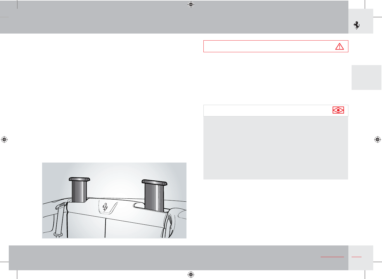
65
2
Safety
Roll bar
The active (ejectable dynamic) roll bar has been designed and
installed to maintain the survival area of the occupants in the event
of a vehicle roll-over.
The active roll bars are controlled by the ECU that activates them
when there is a strong roll around the longitudinal axis of the
vehicle and there is a risk of vehicle roll-over.
In the case of a roll that exceeds the calibration thresholds, the
ECU will release the roll bar locking system and deploy the roll
bars in a few tenths of a second. Once deployed, the active roll
bars help to maintain an occupant survival area together with the
windscreen bay (and the hard top if used).
Warning
The active roll bars do not reduce the risk of ejection of any
occupants who are not wearing their seat belts or the risk of
injury caused by impact with the interior of the vehicle in the
event of a collision or roll-over.
The seat belts must always be fastened to reduce the risk of
being thrown out of the vehicle and reduce the risk of injury
caused by impact with the interior of the vehicle.
Important note
The active roll bars are also deployed in the event of a
sufficiently severe rear or side collision as a precautionary
measure against subsequent roll-over of the vehicle.
Since it is impossible to gauge vehicle dynamics and movements
of the occupants in an accident, the active roll bars are also
activated as a precautionary measure in the event of:
- sufficiently severe head-on collisions (that activate the front
airbags) if they have caused a cut-out of the fuel supply;
- sufficiently severe side or rear collisions.
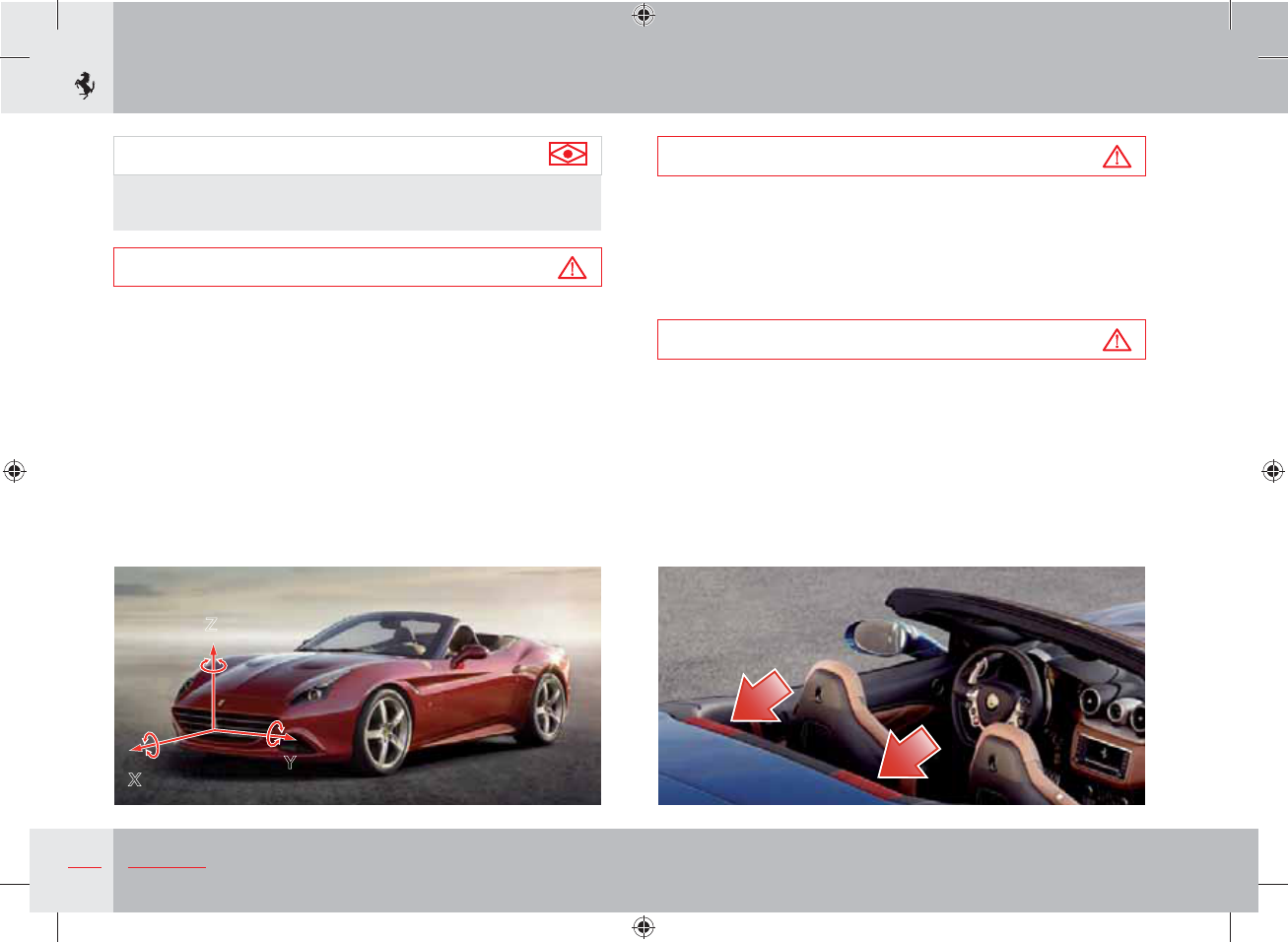
66 Safety
Warning
Never place objects over or near the roll bar covers.
If the roll bar is activated, they may delay or prevent its ejection.
They could also be projected into the passenger compartment
at such high speed as to seriously jeopardise the safety of the
occupants.
Warning
If activated, the roll bar must be replaced.
Contact the Ferrari Service Network.
Important note
The active roll bars are not deployed in the event of a roll-over
around a transverse axis (Y axis in the figure).
Warning
Do not travel with rear occupants resting their heads on the
roll bar covers, facing rearward or seated on top of the roll bar
covers.
If activated, the roll bars will increase the risk of injury.
Z
XY
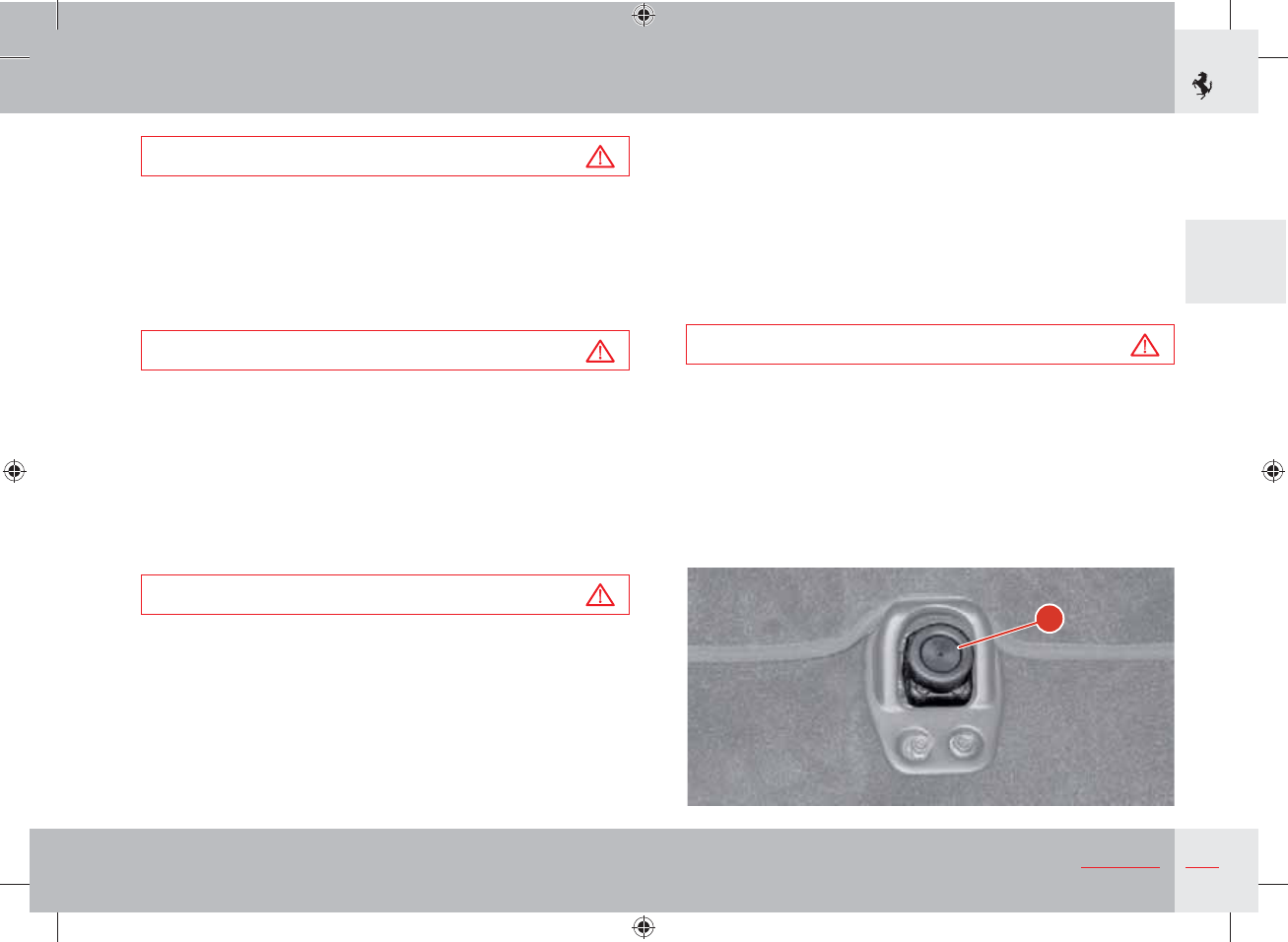
67
2
Safety
Warning
The roll bar is a pyrotechnic-powered system.
The system cannot be repaired.
Risk of injury if accidentally activated.
Each operation must only be performed by authorised staff.
Contact the Ferrari Service Network.
Warning
Never modify the roll bar modules. Do not damage the roll bar
module covers (for example pinning something onto them or
pressing objects against their covers).
If, for any reason, a roll bar cover gets damaged, have the roll
bar module immediately checked by the Ferrari Service
Network.
Activation of a damaged roll bar module could cause serious or
fatal injuries.
Warning
The roll bar modules are subject to wear and tear and must be
replaced at the intervals indicated in the “Warranty Booklet”
even if the vehicle has NOT been involved in a collision.
"
Fuel inertia switch
This is a safety switch A located in the passenger compartment, on
the floor in front of the driver seat, which deactivates the fuel pump
relays if a collision occurs.
A symbol on the TFT display and the hazard warning lights come
on to indicate that the switch has been activated.
When activated, the doors are also unlocked (if locked) and the
central dome light comes on.
Warning
The system can be reactivated by pressing the button on the top
of the switch.
68 Safety
In the event of ABS activation under braking, these regulation
cycles will be repeated until the car comes to a stop or pressure on
the brake pedal is reduced.
In addition, the system offers the following advantages:
- Driving stability (no skidding): even in the event of sharp braking
approaching wheel locking.
- Manoeuvrability (no side-skidding on sharp turns).
This means that even when an emergency situation requires sudden
braking, the driver can avoid obstacles, or brake on a curve, without
affecting the vehicle stability.
Warning
The ABS system features remain unaltered as long as the speed
limit for the tyre side grip is not exceeded. When this limit is
exceeded, vehicle skidding cannot be avoided.
- Optimal braking distance:
depending on the type of road surface, the braking distance may
be reduced by as much as 40%.
Warning
The ABS system does NOT exempt the driver from driving
carefully and responsibly at all times.
ABS and EBD
This is a safety device which activates to prevent wheel locking if
the driver depresses the brake pedal too sharply, especially under
poor grip conditions.
The system is composed of:
- electro-hydraulic unit;
- electronic brake-force distribution EBD;
- four speed sensors on the wheels, incorporated in the bearings;
- the entire ESP sensor system (steering angle sensor,
accelerometer, yaw sensor, etc.).
These features add to the vehicle’s standard braking system,
without changing its characteristics.
Important note
When the ABS system is active, during emergency braking or in
poor grip conditions, a “pulsing” sensation will be felt through
the brake pedal. Hold the brake pedal down to continue the
braking action.
When one of the wheels starts locking, the hydraulic control unit
controls the braking circuit by running a 3-phase cycle:
- reduction (if necessary);
- maintenance;
- pressure increase in the hydraulic circuit.
69
2
Safety
Important note
The ABS system improves braking distances in all conditions,
but cannot compensate for the driver's failure to maintain safety
distances or loss of control in poor road conditions.
The purpose of the ABS system is to maximise the efficacy of the
brake system in all situations, and, in particular, at the limit of grip
of the tyres and in changing road surface conditions.
ESC - Stability and Traction Control
The electronic stability control ESC consists of two main systems:
VDC Vehicle Dynamics Control, performed through the
braking system
F1-Trac traction control, performed through engine torque
modulation, depending on maximum grip on the road
and secondary systems that are always active such as the ABS and
EBD.
To provide optimal control in different driving and grip conditions,
three different setting levels have been designed:
- Level 1: ensures stability and maximises traction on every type
of road surface, both in low (Manettino set to Comfort) and very
low grip conditions, by means of engine and brake control (in this
condition, the standard ASR system activates instead of the F1-
Trac function).
- Level 2: ensures stability and maximises traction only in medium-
to high-grip conditions (Manettino set to SPORT) optimising
engine and brake control.
- Level 3: ESC deactivated (Manettino set to ESC OFF). Stability
is not ensured, but all the other features always present in the
other settings, such as the ABS and EBD, remain active. The
VDC system remains active under braking.
F1-Trac
F1-Trac is directly derived from Ferrari's expertise in F1 vehicles.
This system optimises traction by controlling engine power delivery.
F1-Trac is faster and more accurate than the traditional control
systems, and is capable of delaying and minimising engine torque
adjustments as required, in order to ensure the desired trajectory.
The system estimates the maximum available grip in advance, by
continuously monitoring the relative wheel speed and using an
auto-adaptive operating logic. Comparing this information with
the vehicle dynamics model stored in the control system, F1-Trac
optimises the vehicle behaviour by controlling engine torque
delivery.
Important note
F1-Trac does not work when the Manettino is set to the ESC
OFF driving mode.
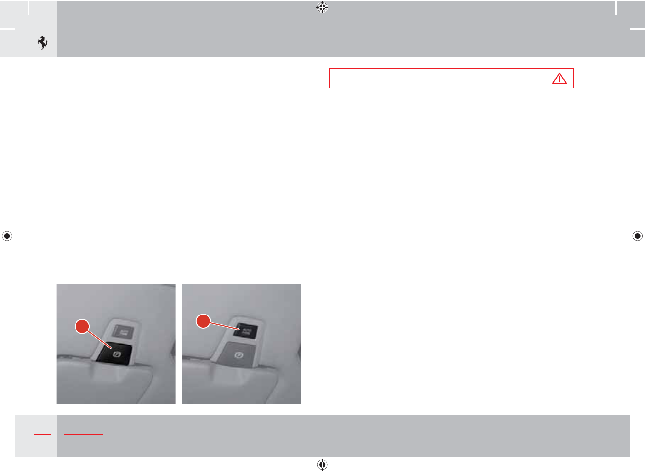
70 Safety
EPB - Electric parking brake
On this vehicle the parking brake is actuated by an electric motor.
The parking brake can be applied and released by pulling a special
lever A on the dashboard to the left of the steering wheel. With the
ignition key turned to II, the relative indicator on the instrument
panel (see page 152) lights up to indicate when the parking brake
is engaged.
To release the parking brake, pull lever A and keep the brake pedal
pressed. If the ignition key is in position II, the warning light will go
out when the parking brake has been fully released.
The electric parking brake can be used as an emergency brake
when the vehicle is in motion. If this is the case, the system acts on
all four wheels until button A is released by communicating with
the ESP system which prevents locking.
#
"
Warning
Always apply the parking brake when the vehicle is parked.
The vehicle should be blocked. If this is not the case, please
contact the Ferrari Service Network.
Autopark Function
The EPB Autopark function automatically activates the electric
parking brake when the engine is switched off. At each Key-on, the
Autopark function is always active by default: this means that the
driver does not need to apply the parking brake when the engine is
switched off.
However, the function can be temporarily deactivated before
switching off the engine by pressing the AUTO PARK B button:
the message “PARK OFF” is displayed on the TFT display for
5 seconds. If this is the case, the parking brake should be manually
applied by pulling lever A once the engine has been switched off.
To re-enable automatic EPB engagement at the next key-off, press
button B again; the message “PARK ON” is displayed on the TFT
display for 5 seconds.
“Automatic Vehicle Holding” AVH function
The electric parking brake provides optimised release when the
vehicle starts up due to its Automatic Vehicle Holding function:
once the engine has started, the system keeps the vehicle braked
through intervention of the braking system rather than through the
parking brake shoes.
For further information, refer to pages 18-1.
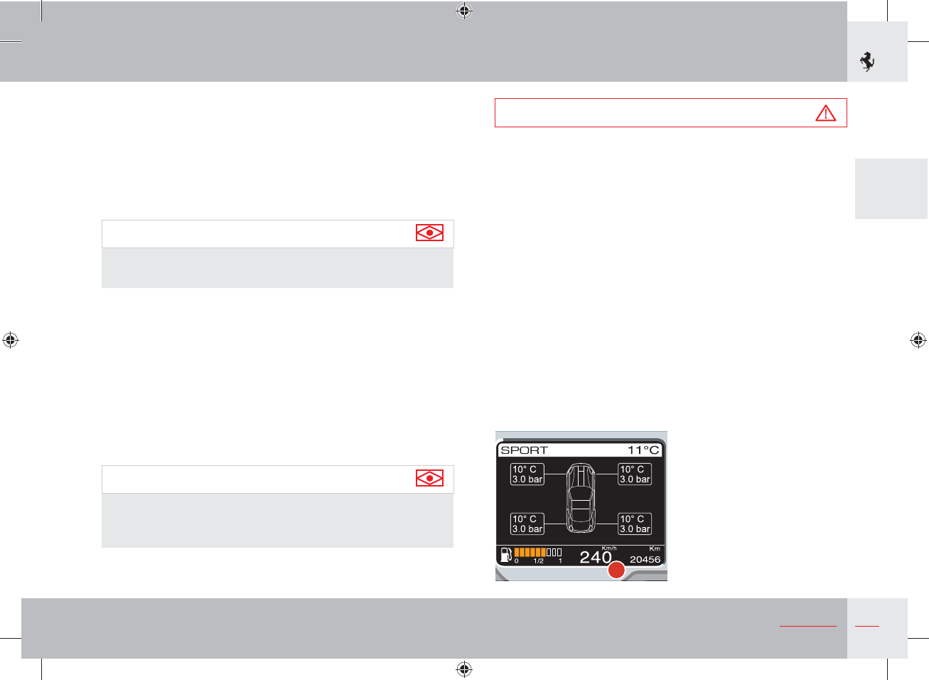
71
2
Safety
Tyre temperature and pressure monitoring
system (TPMS)
The vehicle is equipped with a system that measures the tyre
pressure and temperature using special sensors fitted inside the
wheel rims next to the air valve. These sensors transmit a signal
that is received by the antennas on the car body, behind the gravel
guards, that are connected to the ECU.
Important note
The system may be affected by radioelectrical interference from
devices that use similar wavelengths.
The ECU processes this information and transmits data on tyre
pressure and temperature and any system errors to the instrument
panel.
The signal transmitted by the ECU activates symbols on TFT
display (see page 151) with two priority levels: a soft warning (sw)
if the pressure loss compared with the nominal pressure exceeds
0.2 bar and a hard warning (hw) if it exceeds 0.5 bar or there is a
dynamic loss of over 0.2 bar/min.
The system can be calibrated using the special menu item in the
TFT display (see page 132).
Important note
System calibration using the special menu item on the TFT
display is necessary after replacement or inflation of a tyre or
tyres.
Warning
The TPMS warns the driver that the tyre pressure has
decreased. However, this does NOT exempt the driver from
periodically checking with a pressure gauge that the tyres are
inflated to the indicated pressure.
The system does NOT warn the driver of damage to the tyres by
external agents.
Display of messages on the TFT display
By using the commands on the left TFT display (see page 130),
the driver can access the TYRES screen page which displays the
vehicle symbol with the pressure and temperature values of each
tyre as shown in example 1.
1
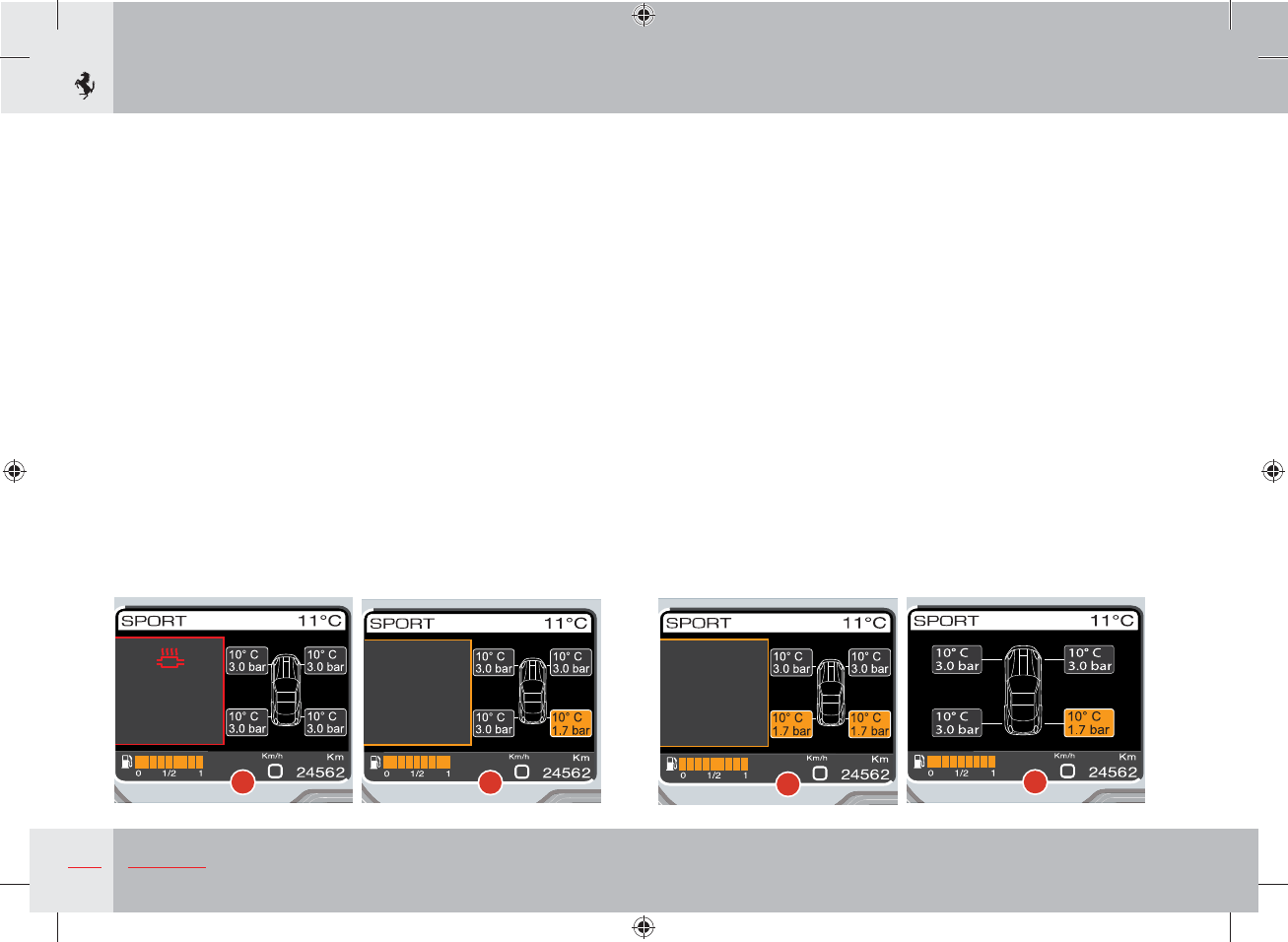
72 Safety
5
The screen page is displayed for 20 seconds and then the screen
page that was previously displayed reappears. If the failure
persists, the screen page shown above (example 3 or 4) will be
automatically displayed for 20 seconds the next time the engine is
started.
The driver can call up the TYRES screen page at any time to
display which tyres have low pressure (example 5).
If an event occurs that needs to be viewed when the TYRES screen
page is being displayed, the screen is displayed in reduced size as
in the following example 2:
Once it has been displayed, the TYRES screen page is displayed
again. For further information, refer to the “Fault visualisation
logic” paragraph on page 146.
Low pressure
Regardless of the type of screen page on the left TFT display, when
the instrument panel receives the signal from the tyre pressure
ECU that the pressure level of one or more tyres is below the alarm
threshold, the screen page shown in example 3 (for a warning
related to only one tyre) or example 4 (for a warning related to
several tyres) appears immediately.
2
Catalysts temp.
too high
Engine
performance
limited
3
Check tyre
pressure
4
Check tyre
pressure
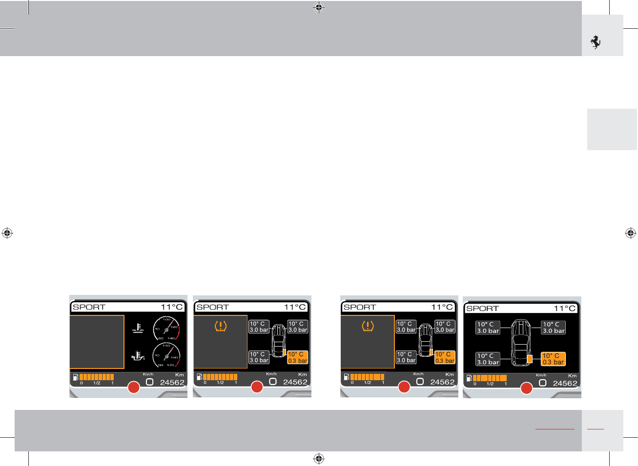
73
2
Safety
Occasionally, the system may not detect which wheel signals
a failure. If this is the case, then only the message “Check tyre
pressure” will be displayed as shown in example 6.
Tyre puncture
Regardless of the type of screen page on the left TFT display, when
the instrument panel receives the signal from the tyre pressure
ECU that the pressure level of one or more tyres is below the
alarm threshold, the screen page shown in example 7 (warning
not to proceed for vehicles fitted with normal tyres) or example 8
(warning to proceed at a maximum speed of 80 km/h for vehicles
fitted with Run Flat tyres) appears immediately. At the same time, a
warning light comes on on the panel (see page 151) in fixed mode.
The screen page is displayed for 20 seconds and then the screen
page that was previously displayed reappears whereas the warning
light remains on in fixed mode.
If the vehicle is fitted with normal tyres, the fault is displayed with
the same display logic applicable for other priority 0 faults (see the
paragraph “Fault visualisation logic” on page 146) until the correct
operating conditions are restored and the system is subsequently
recalibrated.
If the vehicle is fitted with Run Flat tyres, the maximum distance
allowed in a “tyre puncture” state is 100 km. The instrument panel
will calculate the residual tyre life and will redisplay the screen
page shown in example 8 after 50 km. The same screen page
(warning not to exceed a maximum speed of 80 km/h) is displayed
if the vehicle exceeds 80 km/h.
Once the distance of 100 km has been exceeded, the panel displays
the screen page shown in example 7 (warning not to proceed).
If you call up the TYRES screen page, you can identify the
punctured tyre at any time (example 9).
7
o tyre
press re
o not
proceed
8
tyre
pressure
spee
kh
Check tyre
pressure
69
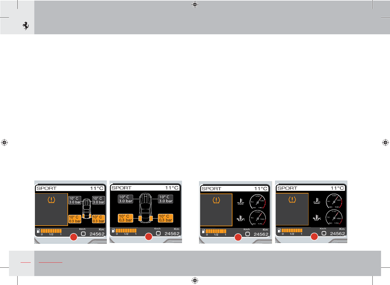
74 Safety
If another tyre is punctured, the instrument panel will update the
number of km (mi) which can still be driven according to the
distance driven after the previous puncture and will display the
screen page shown in example 10.
While a priority level 0 (normal tyre puncture) or priority level 2
(Run Flat tyre puncture with maximum speed limit not exceeded
and tyres still usable) fault is active on the display, the driver may
press OK to “ESCAPE” (see page 146): the screen page disappears
whereas the warning light on the panel remains on in fixed mode.
As above, the TYRES screen page can be called up at any time to
display which tyres are punctured (example 11).
Occasionally, the system may not detect which wheel signals a
failure. If this is the case, the screen page shown in example 12 (for
vehicles fitted with normal tyres) or example 13 (for vehicles fitted
with Run Flat tyres) will be displayed.
The symbol and message are displayed for 20 seconds and then the
screen page that was previously displayed reappears whereas the
warning light remains on in fixed mode.
If the vehicle is fitted with Run Flat tyres, the instrument panel will
calculate the residual tyre life and will redisplay the screen page
shown in example 13 after 50 km. The same screen page (warning
not to exceed a maximum speed of 80 km/h) is displayed if the
vehicle exceeds 80 km/h. Once the distance of 100 km has been
exceeded, the panel displays the screen page shown in example 12
(warning not to proceed).
10
o tyre
press re
a speed
mh
11
Low tyre
pressure
Do not
proceed
12
Low tyre
pressure
Max speed
80 km/h
13
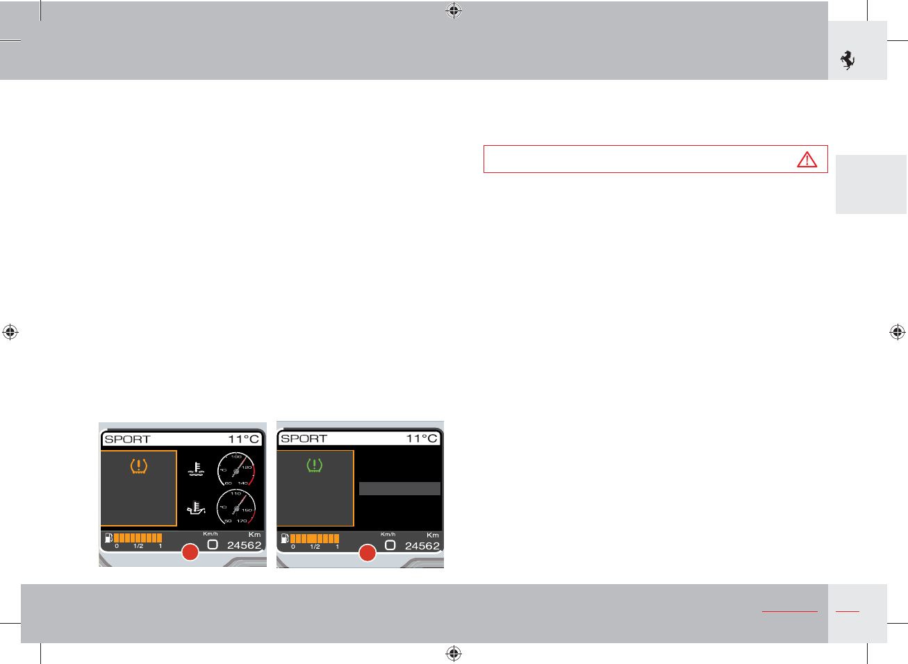
75
2
Safety
System not calibrated
If the system has not been calibrated or one or more tyres have
been replaced, the symbol and message shown in example 14 will
be displayed. Simultaneously, the specific warning light on the
instrument panel (see page 151) starts flashing, and continues to
flash for 90 seconds.
When the display cycle ends (20 seconds), the symbol and message
disappear and the screen page that was previously displayed
reappears whereas the warning light remains on until the system
has been calibrated.
The TPMS can be calibrated using the special menu item in the left
TFT display with the ignition key in position II and the engine off.
To calibrate the TPMS, call up the MENU screen page on the left
TFT display (see page 132) with the ignition key in position II and
the engine off. Once the MENU screen page appears, select the
items “Car setup”, “Calibr. TPMS”.
When the Menu item is displayed and the subsequent calibration
accepted, the screen page shown in example 15 appears for 5
seconds.
Warning
Before calibrating the system, make sure that the tyre pressure
corresponds to the indicated pressure values (see page 30). If
this is not the case, the TPMS may issue wrong low pressure
indications.
TPMS
not calibrated
Execute
calibration
14
Calibration
activated
Display setup
Date/Hour
Car setup
Dimming
Language/M.U.
15
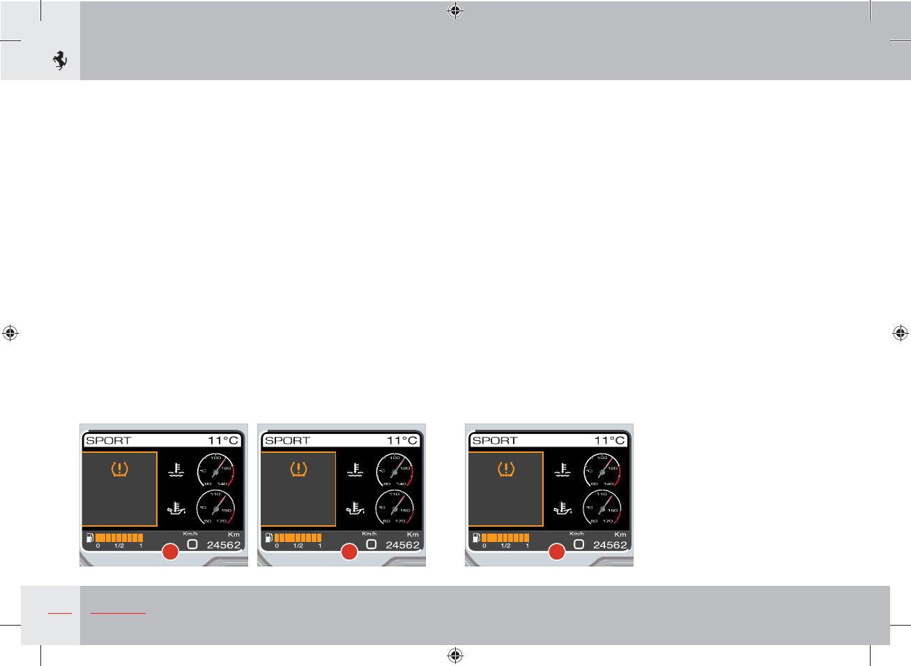
76 Safety
TPMS failure
The screen page shown in example 16 is displayed in the following
circumstances:
- malfunction in the circuit and/or wiring connecting the ECU
- signal is not received by one or more sensors due to a faulty,
broken or flat battery
- fault in the TPMS ECU.
Simultaneously, the specific warning light on the instrument
panel (see page 151) starts flashing, and continues to flash for
90 seconds. The warning light then remains on in fixed mode until
the situation is corrected.
The TYRES screen page cannot be called up by the driver.
System temporarily not active
The screen page shown in example 17 is displayed in the following
circumstances:
- overheating of sensors
- during calibration (the TPMS ECU does not recognise the sensors)
- radio frequency that interferes with the wheel sensor signal.
Simultaneously, the specific warning light on the instrument
panel (see page 151) starts flashing, and continues to flash for 90
seconds. The warning light then remains on in fixed mode until the
situation is corrected.
The TYRES screen page cannot be called up by the driver.
System not active
For a few seconds at key-on, if the TPMS has been deactivated by a
diagnostic tool, the screen page in example 18 is displayed.
Simultaneously, the specific warning light on the instrument
panel (see page 151) starts flashing, and continues to flash for
90 seconds. The warning light then remains on in fixed mode until
the situation is corrected.
The TYRES screen page cannot be called up by the driver.
TPMS failure
16
TPMS
temporarily
inactive
17 18
inacti e
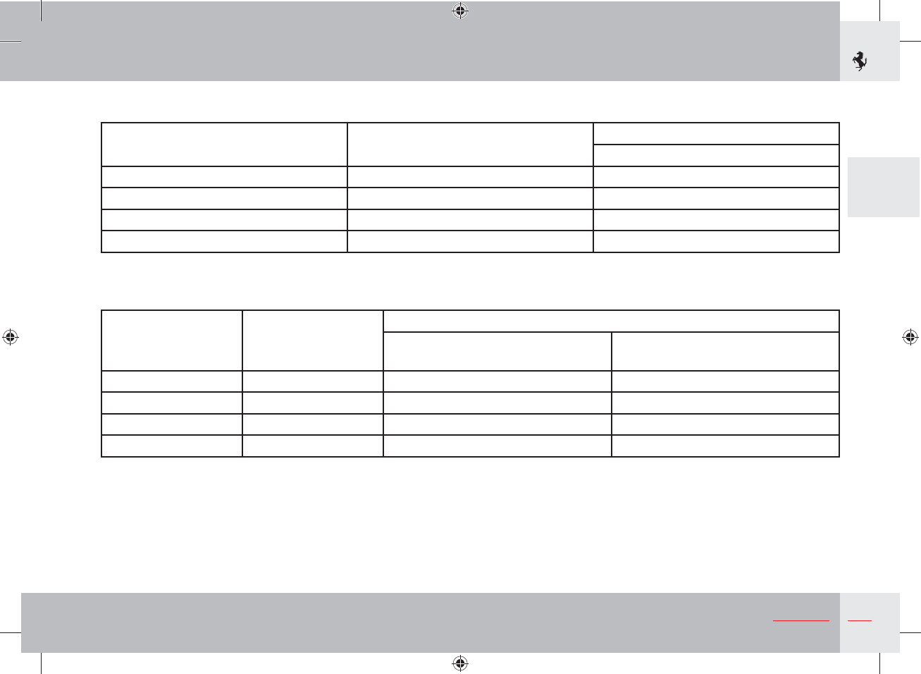
77
2
Safety
TAB 1. Child restraint systems that can be installed on the front passenger seat with 3-point seat belts
GROUP WEIGHT RANGE SEAT
Front passenger
0 0 - 10 kg X
1 9 - 18 kg UF - L
2 15 - 25 kg UF - L
3 22 - 36 kg UF - L
TAB 2. Child restraint systems that can be installed on the rear seats with 3-point seat belts
GROUP WEIGHT RANGE
SEAT
Driver-side,
lateral rear
Opposite driver-side,
lateral rear
0 0 - 10 kg X U - L
1 9 - 18 kg U - L U - L
2 15 - 25 kg U - L U - L
3 22 - 36 kg U - L U - L
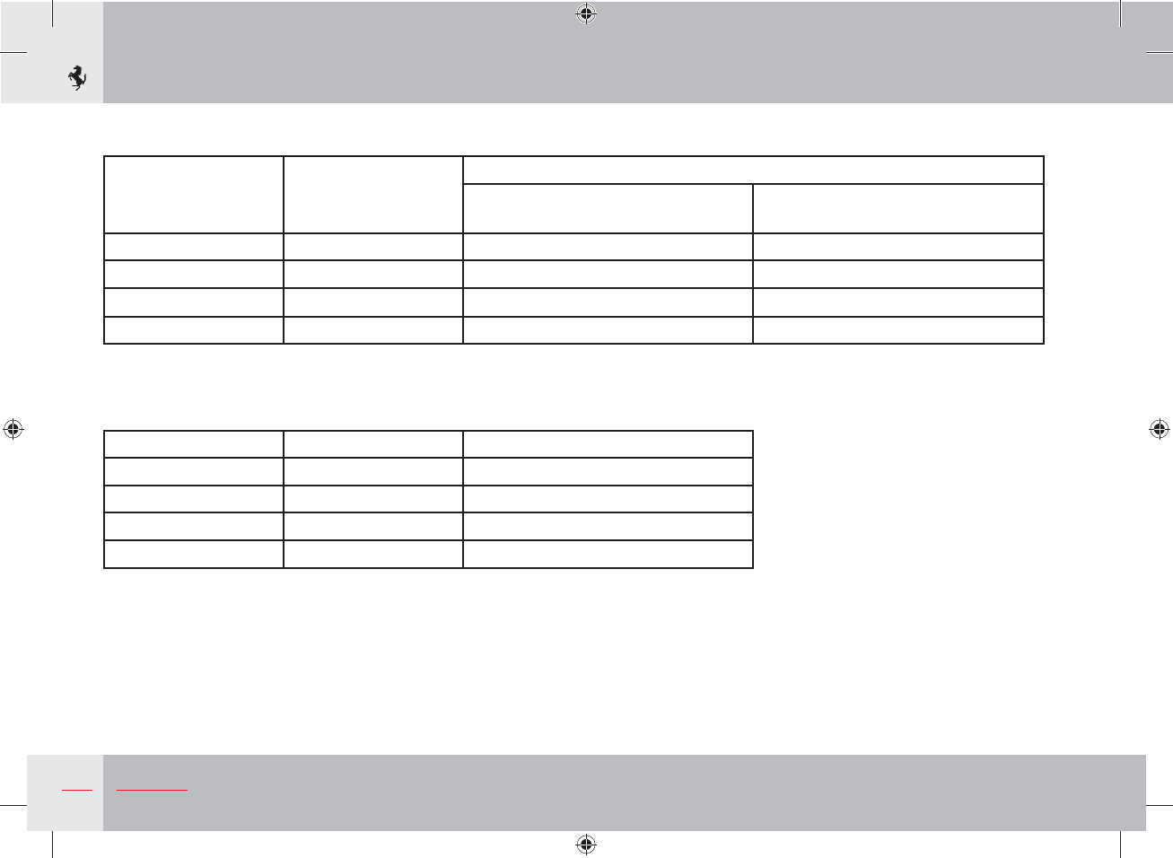
78 Safety
TAB 3. Child restraint systems that can be installed on the rear seats with ISOFIX
GROUP WEIGHT RANGE
SEAT
Driver-side,
lateral rear
Opposite driver-side,
lateral rear
0 0 - 10 kg X L
1 9 - 18 kg L L
2 15 - 25 kg X X
3 22 - 36 kg X X
TAB 4. Special Ferrari Baby Smart™ child restraint systems (produced by Britax-Römer)
GROUP WEIGHT RANGE Name
0 0 - 10 kg BABYSAFE Plus
1 9 - 18 kg DUO Plus
2 15 - 25 kg KID Plus
3 22 - 36 kg KID Plus
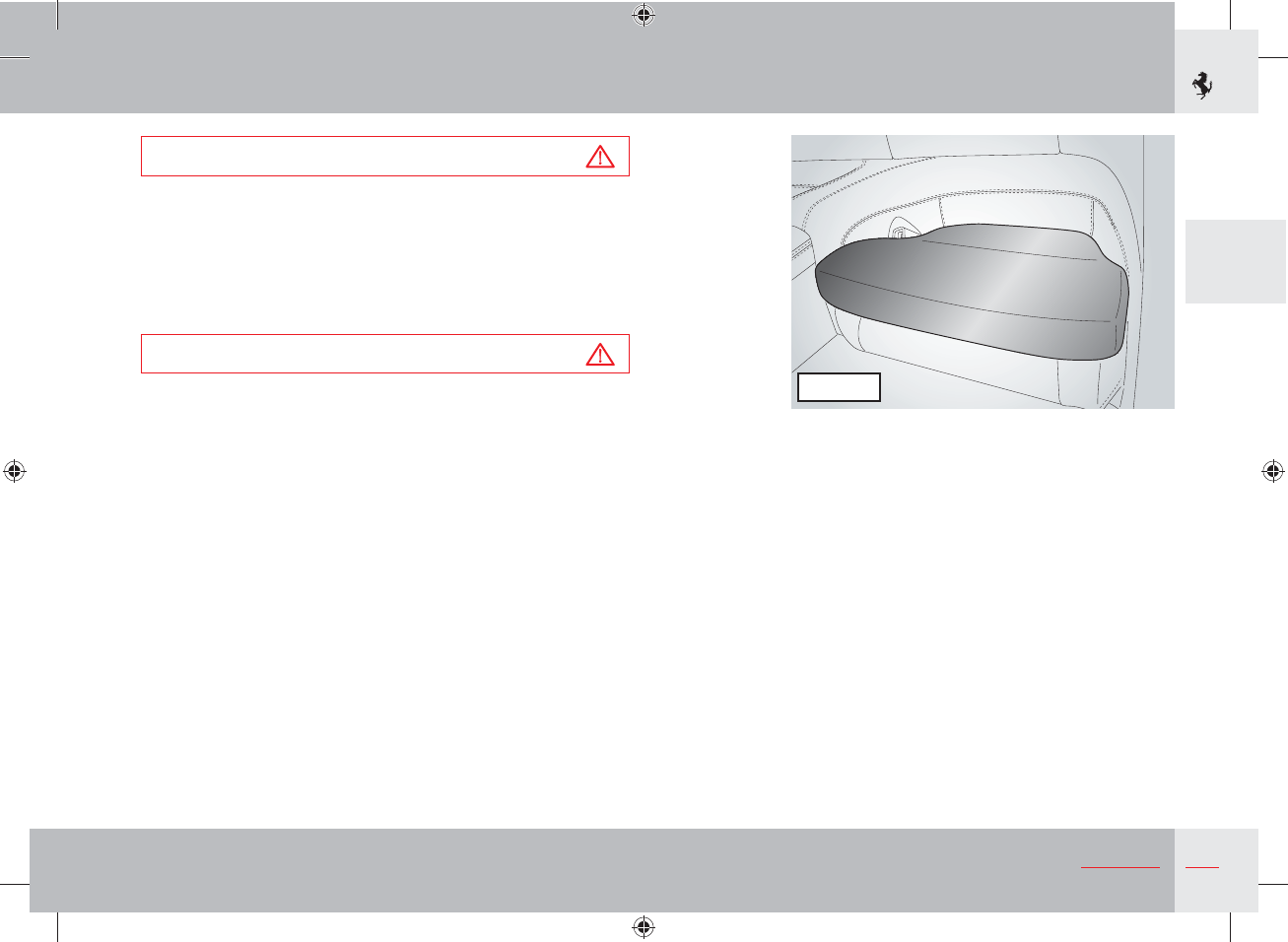
79
2
Safety
Warning
Before installing the KID Plus car seat on the rear seats, the
cushion supplied with the car seat must be placed on the seat
cushion as shown in Figure 1. This cushion must be used to
ensure that the KID Plus car seat is correctly installed.
If you already have a KID Plus car seat but no cushion for rear
seat installation, contact the Ferrari Service Network.
Warning
Only use the cushion with the KID Plus car seat. Remove the
cushion if the seat is occupied by an adult.
Key
U = suitable for “Universal” category restraint systems homologated for use in this weight group.
UF = suitable for forward-facing “Universal” category restraint systems homologated for use in this weight group.
L = suitable for the special restraint systems listed in TAB 4. These restraint systems can be “vehicle specific”, “limited” or “semi-universal”.
X = seat not suitable for children in this weight group.
Figure 1

1. General
2. Safety
3. About your Vehicle
4. Advice for Emergency Situations
5. Care of the vehicle
6. Glossary
7. Table of Contents
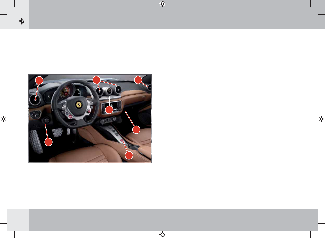
82 About your Vehicle
1
5
3
4
2
1 1
Controls overview
Ref. Control Page
1Adjustable air vents 202
2Glove compartment 202
3Hazard warning lights control 128
4Manometer display 156
5Light switch 125
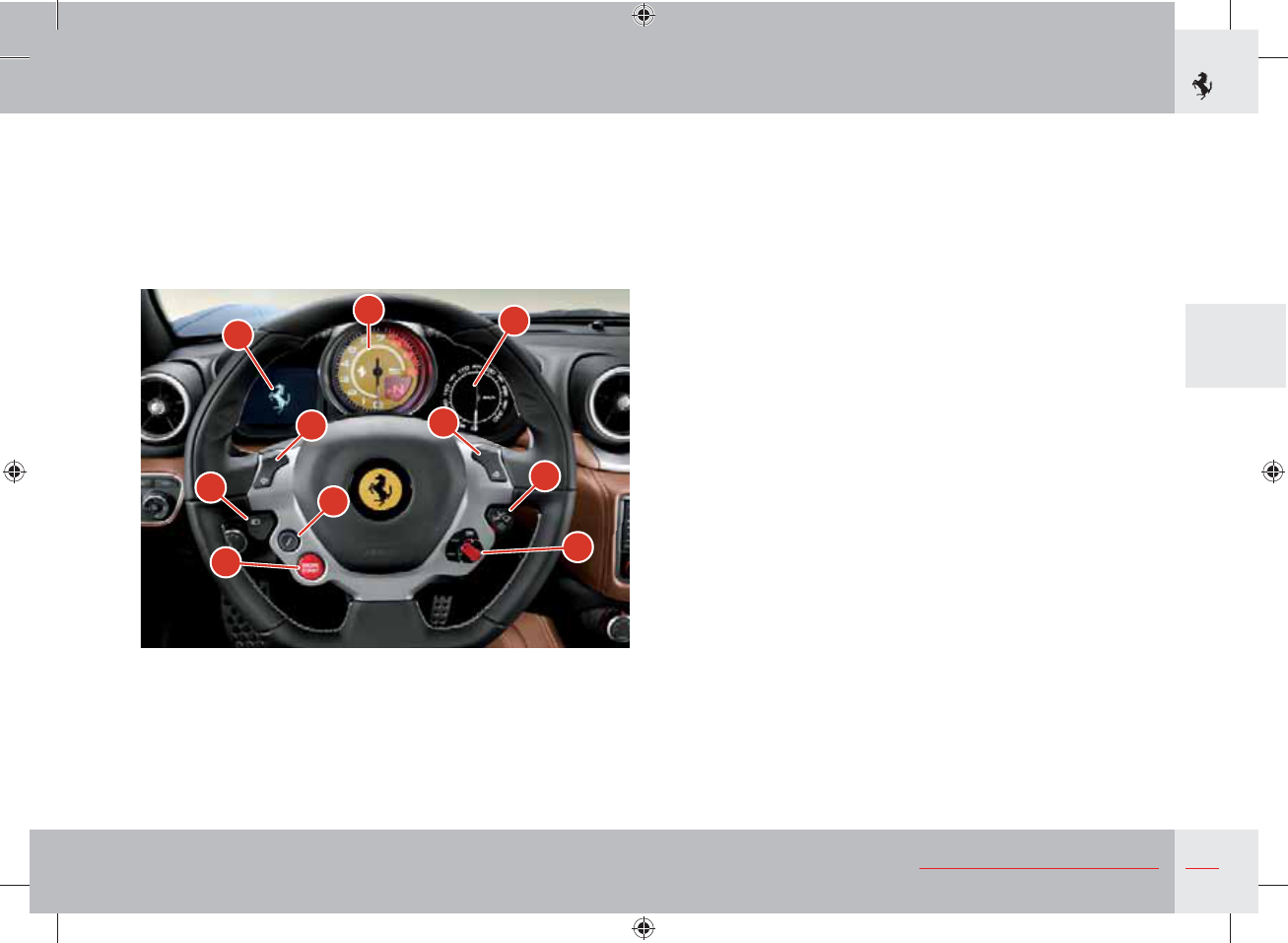
83
3
About your Vehicle
Ref. Control Page
6“ENGINE START” button 159
7“Manettino” control 159/177
8Rev counter and gearbox display 153
9TFT display 130
10 Speedometer 95/153
11 Turn indicators 127
12 Suspension damping delink button 181
13 High beam and flashing lever 125
14 Windscreen wiper stalk 161
67
10
9
8
11 11
12
13 14
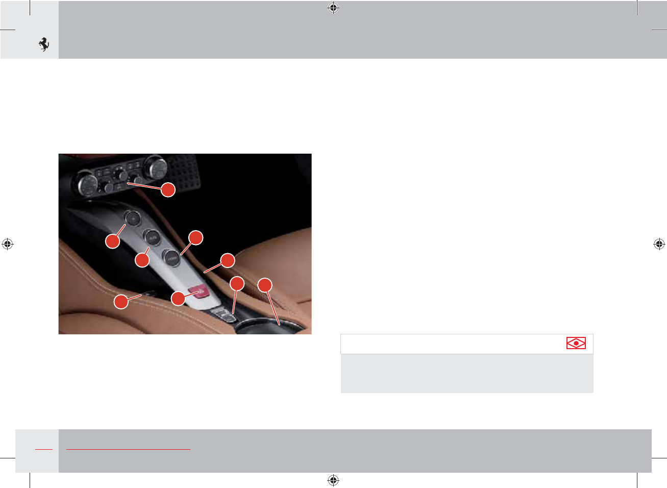
84 About your Vehicle
Ref. Control Page
15 Cup holder
16 Power window controls 92
17 “R” reverse control 169
18 “AUTO” control 172
19 “LAUNCH” control 180
20 Air conditioning controls 199
21 Retractable hard top opening/closing button 118
22 Emergency light button 128
15
16
21
19
20
17
18 16
22
Important note
The position of the “R”, “LAUNCH” and “AUTO” buttons on the
centre console may vary according to the market. The button
functions are the same.
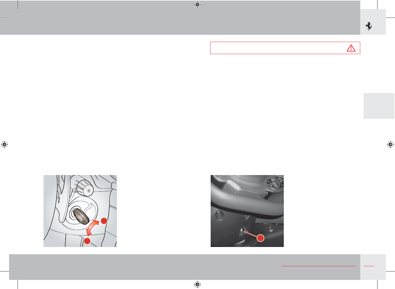
85
3
About your Vehicle
Ignition switch
The ignition key can be turned to 2 positions:
Position 0 - Stop
Engine off, key removable.
The hazard warning lights and the parking lights can be activated.
Position II - Ignition
Turning the key to this position, the TFT display will check the
signals coming from the vehicle systems.
II
0
Warning
Always remove the key from the ignition when you get out of
the vehicle!
Never leave children unattended in the vehicle.
Key lock
If more than 20 seconds elapse after turning the key to position 0,
the key lock device must be released to remove the key.
Press button K in the slot under the steering wheel and remove the
key at the same time.
K
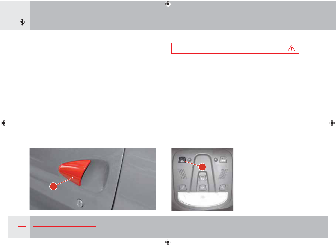
86 About your Vehicle
"
B
Doors
When a door is opened or closed, the window automatically moves
down by approximately 2 centimetres (to its “target position”) to
avoid colliding with the upper weather strip.
When the door is closed, the window automatically moves up until
it reaches the “upper limit”.
Opening from the outside
Using the remote control, deactivate the alarm and the central door
locking system, or turn the key in the lock to deactivate the central
door locking system.
To open the door, pull handle A: the window will move down to its
“target position”. When the door is closed, the window will move
up until it meets the upper limit.
Locking and opening the doors from the inside
Warning
Always carefully check manually that the doors have been
closed properly to prevent them from opening while driving.
Both doors can be locked by activating/deactivating the “LOCK/
UNLOCK” B button on the roof panel. To lock the doors, press
button B; when the door lock is activated, the light on button B
comes on. To deactivate the door lock, press button B until the
light goes out.
The rolling lock function, which automatically locks the doors when
the vehicle speed reaches or exceeds 20 Km/h, may be activated
from the “Car setup” menu accessible from the TFT display of the
instrument panel (see page 132).
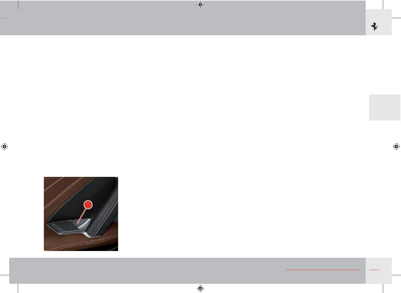
87
3
About your Vehicle
C
If you pull handle C to open the door, the window will move down
to its target position. When the door is closed, it will move up until
it meets its upper limit.
If handle C is lifted without opening the door, the window will
move down to its target position and stop and if the door is not
opened after 2 seconds, the window will move back up until it
meets the upper limit. Therefore, to open the door, release handle C
and pull it again.
When the opening handle is operated, both doors are unlocked.
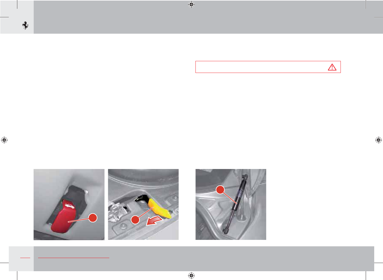
88 About your Vehicle
DE
F
Engine compartment lid
Opening
To unlock the engine compartment lid, pull the lever D underneath
the steering column.
Stand in front of the vehicle, slightly lift the lid and pull the
retaining lever E to the side of the lock and lift it.
The lid is held open by two gas struts F.
The engine compartment lid can also be opened with the ignition
key at off.
Closing
Lower the lid until it is closed and press down near the lock until
you hear it click in place.
Warning
Always check manually that the engine compartment lid has
been closed properly to prevent it from opening while driving.
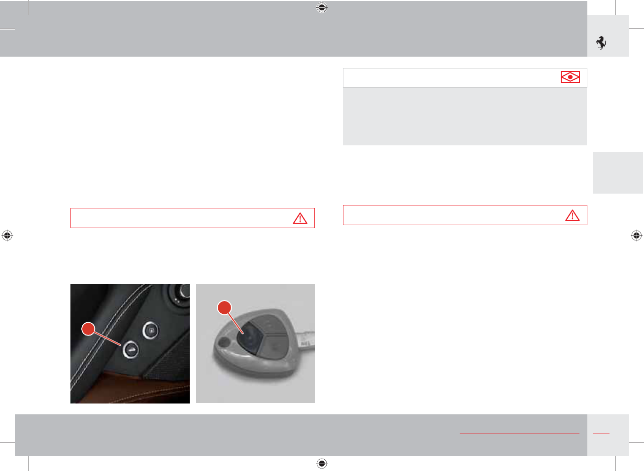
89
3
About your Vehicle
L
H
Luggage compartment lid
Opening
The luggage compartment lid can also be opened with the ignition
key at off.
To open the luggage compartment lid, press button H on the driver
side door or button L on the remote control and hold it for more
than 2 seconds. You can also use the special knob to the right of
the number plate lights or the button between the number plate
lights.
The luggage compartment is illuminated by an internal light that
comes on automatically when the luggage compartment lid is
opened.
Warning
To avoid damage, check there is enough room to open the
luggage compartment lid.
Important note
After removing the battery from the vehicle or disconnecting
it from the electrical system, a door lock/unlock cycle must be
performed using the buttons on the key when reconnecting so
that the release button H resumes normal operation (electronic
system self-acquisition procedure).
Closing
Using the grip on the inside, lower the luggage compartment lid
until it touches the bodywork.
The lock will pull the lid down until it clicks in place.
Warning
Since the lock closes automatically, always keep your hands
away from the area between the luggage compartment lid and
the bumper.
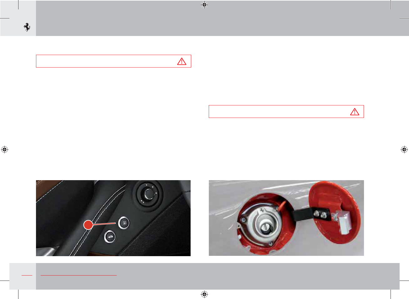
90 About your Vehicle
M
Capless filler neck
This vehicle has a capless filler neck for fuelling. This system allows
you to refuel by opening the fuel filler flap and simply placing the
nozzle in the filler neck without having to unscrew a cap and screw
it up again.
Two flaps placed in series, both with airtight seals, act as a cap.
The external flap is locked by a series of “teeth” and the only way
to open the external flap correctly is by inserting a petrol pump
nozzle.
Warning
Place the nozzle in the filler neck carefully to avoid damaging
the device seal. Do not try to open the external flap of the filler
neck by pushing it with your fingers or lever it open using
unsuitable tools (e.g. screwdrivers). This may damage the
external flap mechanism, compromising the seal integrity and
safety of the system.
Fuel filler cap and flap
Warning
Always turn off the engine during refuelling.
Do not smoke or use open flames when refuelling.
The following can be harmful for your health:
- fuel coming into contact with your skin;
- inhaling fuel vapours.
Opening
To open the fuel filler flap, press button M on the driver side door.
Closing
To close the fuel filler flap, push it until it clicks in place.
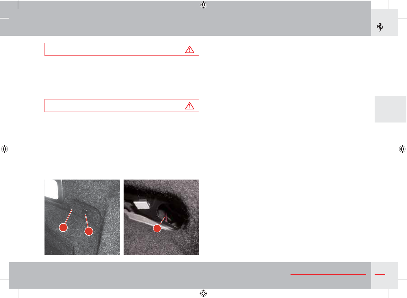
91
3
About your Vehicle
FE
G
Warning
Do not overfill the fuel tank: this may cause the fuel to leak out.
After fuelling, wait for about 5 seconds before slowly removing
the nozzle from the filler neck: in this way, the last drops of fuel
will flow into the tank and will not drip onto the vehicle.
Warning
Do not place funnels or portable container nozzles in the filler
neck.
If you need to refuel from a portable fuel container, use only the
funnel supplied in the tool bag (see page 212) that releases the
automatic closing device.
Emergency Opening
In the event of a failure of the fuel filler flap button, the flap can be
opened manually.
Open the luggage compartment lid, turn the lock E and open the
flap F.
Pull the emergency string G.
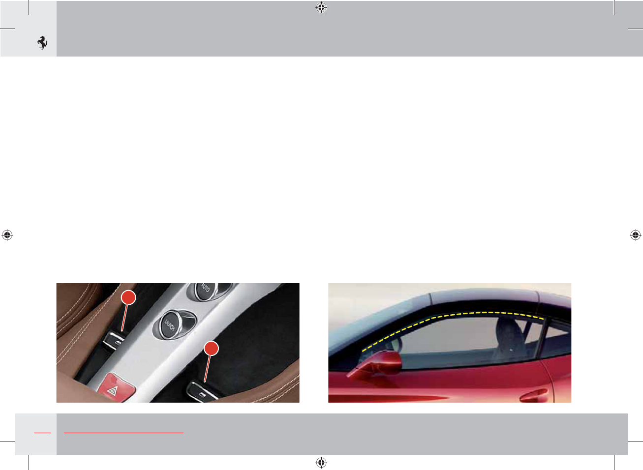
92 About your Vehicle
B
A
Power windows
The power windows can only be used with the ignition key in
position II.
Driver-side power window
Press button A to move the window up or down. This button
allows manual operation (partial opening/closing) or automatic
operation (complete opening/closing). Press button A briefly to
activate manual operation; if the button is pressed at length (over
0.3 seconds) the automatic window operation is activated. The
window will only stop when it reaches the end of its travel or by
pressing the button again.
Passenger-side power window
Press button B to move the window up or down.
Only manual operation is possible (partial opening) to raise the
window: when button B is released, the window stops at the
position reached.
To lower the window, automatic operation is also possible (full
opening): if the button is pressed at length (over 0.3 seconds)
automatic window operation is activated. The window will only
stop when it reaches the end of its travel or by pressing the button
again.
When the door is open, the window can only rise to the “target
position”, to prevent the window from hitting the upper weather
strip when it is closed.

93
3
About your Vehicle
“Global Open” function
Quickly press the “Retractable hard top” button twice to open all
four windows at the same time.
“Global Closed” function
Quickly press the “Retractable hard top” button and then hold it
down to close all four windows at the same time.
Rear power windows
With the driver side front window lowered, press button A again to
lower the driver side rear window.
With the passenger side front window lowered, press button B
again to lower the passenger side rear window.
To raise the rear windows, simply lift button A for the left window
and B for the right window.
Warning
Improper use of the power windows can be dangerous. Before
use, always check that people and objects are at a safe distance.
Pay particular attention during the automatic operation of the
driver-side power window.
To protect the passengers remaining in the car against accidental
activation of the power windows, always remove the key from
the ignition.
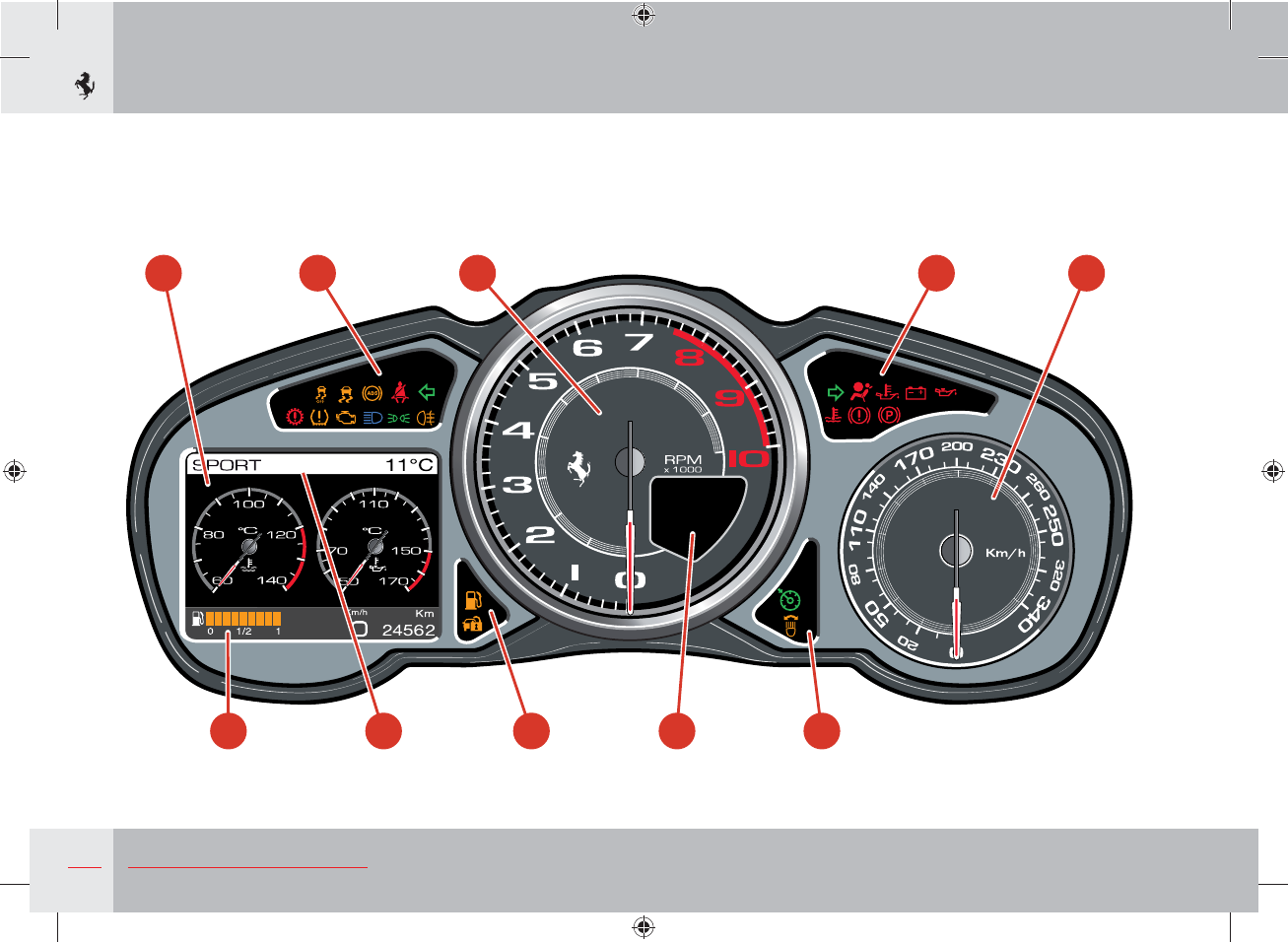
94 About your Vehicle
1 5 3 5 2
7 6 5 4 5
Instruments and gauges
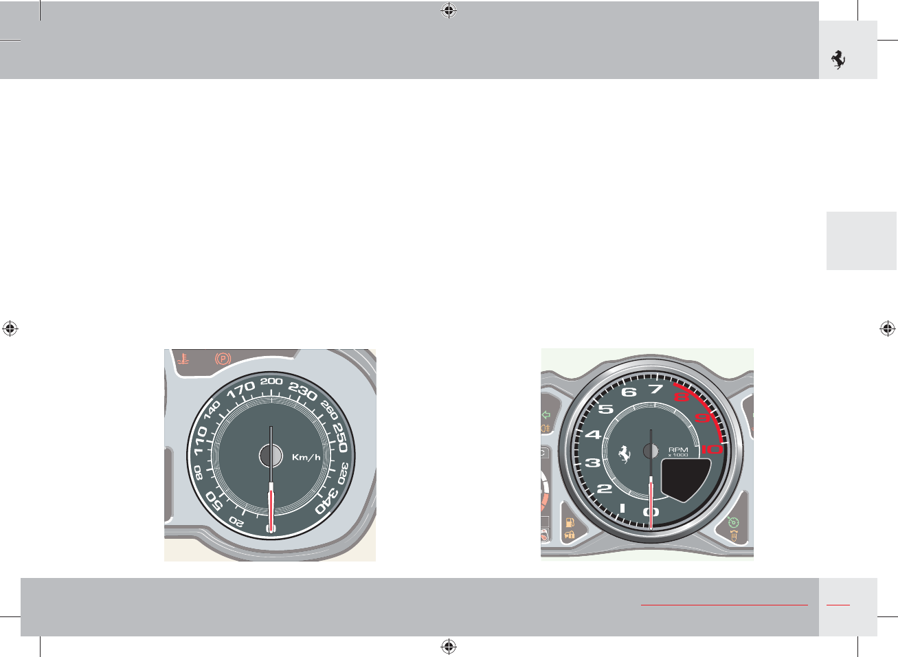
95
3
About your Vehicle
1 TFT Display
2 Electronic speedometer
3 Rev Counter
4 Gear display
5 Warning lights on the panel
6 Manettino status
7 Fuel level
Rev Counter
The rev counter indicates the engine RPM.
The numbers on the dial multiplied by 1000 correspond to the
engine RPM in one minute.
There is a space to the bottom right of the rev counter for the
display which gives information on dual clutch transmission (DCT).
Electronic speedometer
The speedometer indicates the actual speed of the vehicle.
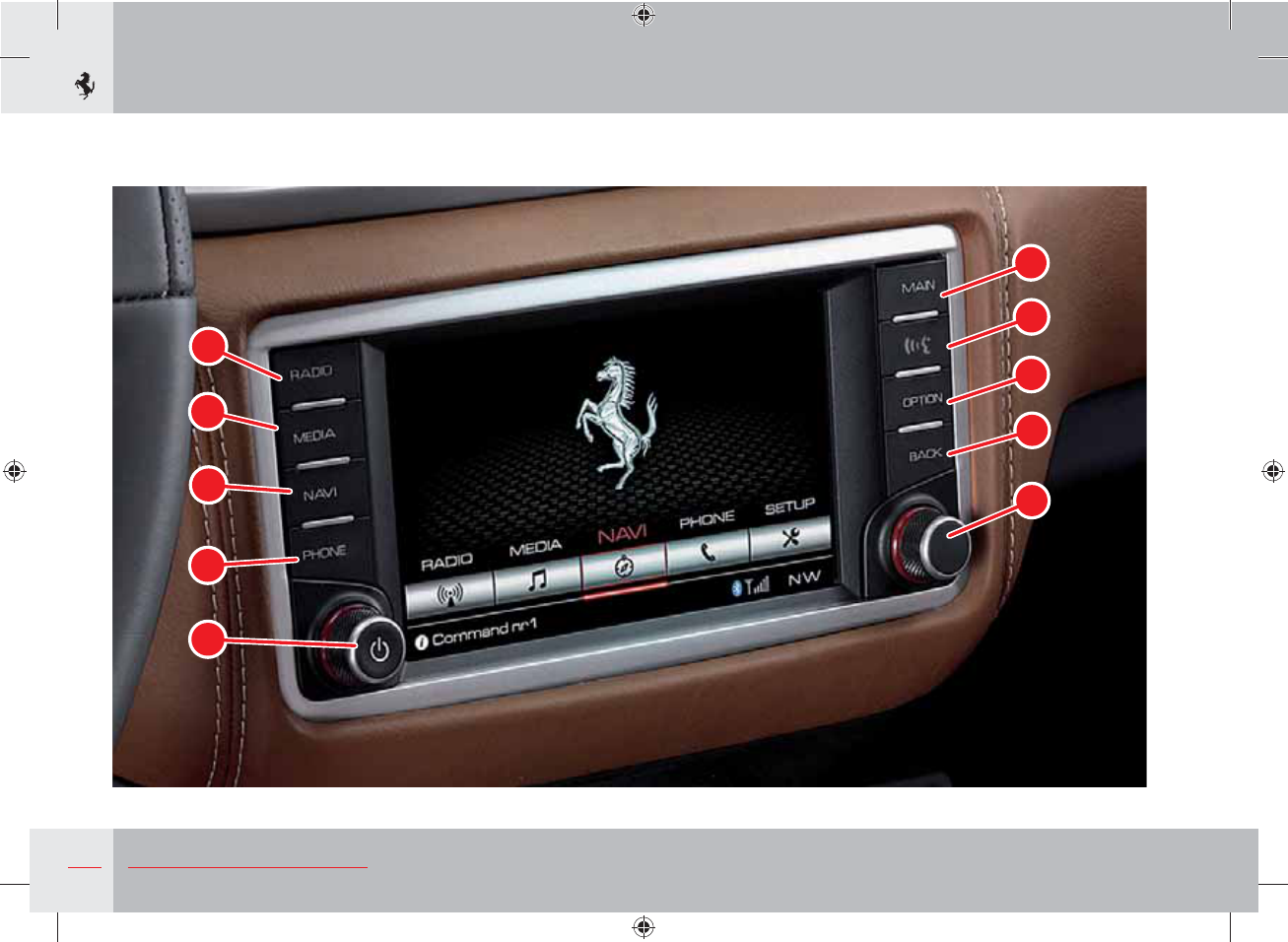
96 About your Vehicle
1
2
3
4
6
7
8
9
10
5
Infotainment system
97
3
About your Vehicle
6Call up main screen
7PUSH TO TALK mode
8Call up Options menu
9Go to previous screen
10 Scroll control - Selection
Controls
1RADIO mode
2MEDIA mode
3NAVI mode
4PHONE mode
5Volume control- ON/OFF
98 About your Vehicle
Introduction
Characteristics
The vehicle infotainment system has the following functions:
- 6.5” touchscreen display
- FM/MW/DAB radio
- CD player (optional)
- USB/iPod®/iPhone® connector
- Satellite navigator
- Bluetooth connection
Recommendations
This manual contains indications (recommendations and
information) intended to avoid actions that may cause accident
or injury. Please observe all recommendations.
Safety information
Read this manual carefully before using the navigation system
for the first time. Observe the safety information described in
the manual. Contact the vehicle manufacturer if in any doubt.
Intended use
The navigation system complies with the standards used in
navigation technology.
Always be aware of the regulations and guidelines in force in
the country where the vehicle will be used.
Software update
The navigation data software can be updated. For the most
recent software, contact the Ferrari Service Network.
Using the infotainment system safely
First of all, read the instructions in the manual carefully in
order to use the system correctly. The infotainment system is
not a toy and we do not recommend allowing children to use
it without adult supervision.
Playing music at a very high volume can cause permanent
damage to hearing and can be distracting for the driver,
especially when driving at high speeds. Therefore, carefully
adjust the volume.
Driving requires your full attention and care. If you are
driving, we do not recommend using the infotainment system.
Important note
Several system functions depend on vehicle speed. For safety
reasons, the touchscreen cannot be used to enter a name (the
name of a street, for example) when the vehicle is moving.
Keep the system away from liquids and others sources of
humidity. In addition to damaging the components, humidity
can cause the electrical devices to shortcircuit.
99
3
About your Vehicle
Connections
Do not force the connectors into the car stereo system ports.
Before connecting them, make sure that the connectors are the
correct shape and size.
The connected cables must not exert any pressure on the
connection.
Touchscreen
Do not touch the display with hard or sharp objects because
they may damage the surface of the touchscreen (pens, USB
sticks, jewellery, etc.).
Do not spray liquid or caustic chemicals directly onto the
screen. Use a clean, dry microfibre lens cleaning cloth to clean
the touchscreen.
If necessary, use a lint-free cloth dampened with a cleaning
solution, such as isopropyl alcohol or an iso-propyl alcohol and
water solution ratio of 50:50. Make sure you follow the solvent
manufacturer’s precautions and instructions.
CD player (optional)
Do not insert damaged, warped, scratched or dirty CDs into
the CD player.
Discs that have been modified with an adhesive label should
not be inserted in the CD player.
Do not insert more than 1 (one) CD at a time into the drive
slot.
Insert supported CD formats only. See the “Disc Mode” section
on page 106 for information on supported CD formats.
GPS navigation antenna
The antenna for the GPS navigation system is mounted in the
dashboard.
Other electronic devices
Other electronic devices (PDA, iPod, computer laptop,
etc.), may be used in the vehicle, some of which may cause
electromagnetic interference with the GPS antenna. If
you notice a reduction in GPS performance, switch off all
appliances and move them as far away as possible from the
GPS antenna.
Warning
As indicated in the general remarks referred to here, the
driver can be distracted by a number of factors including the
navigation/infotainment systems. The infotainment system
should be used by the passenger where possible and, if used by
the driver, should only be used when the vehicle is stationary.
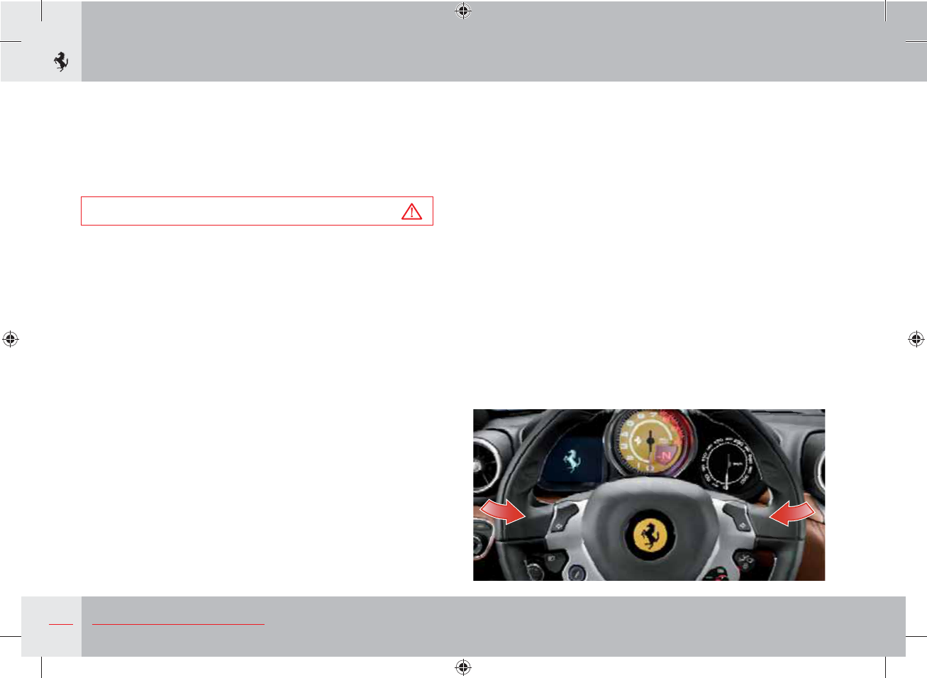
100 About your Vehicle
User interface
The infotainment system information is displayed on the
6.5” display in the centre of the dashboard. Users can interact
with the system by pressing the screen which uses touchscreen
technology and using the controls located on both sides of the
display and behind the steering wheel.
Warning
Do not touch the display with hard or sharp objects because
they may damage the touchscreen surface.
Controls on dashboard
1) RADIO
Press button 1 to go to Radio mode.
2) MEDIA
Press button 2 to go to Media mode.
3) NAVI
Press button 3 to go to Navi mode.
4) PHONE
Press button 4 to go to Phone mode and/or connect a phone.
5) VOLUME CONTROL- ON/OFF
Hold down button 5 to switch the infotainment system on/off
and turn the button to adjust the volume. Quickly press to put the
system into MUTE mode.
6) MAIN
Press button 6 to go to the main infotainment system screen.
7) PTT
Press button 7 to activate the voice commands.
8) OPTION
Press button 8 to access the options menu for the screen that is
displayed.
9) BACK
Press button 9 to go back to the previous screen.
10) SCROLL CONTROL
Rotate button 10 to go from one screen to another and press the
button to select the desired option. The button has dual functions
in Radio and Media modes which can be configured from the
settings menus.
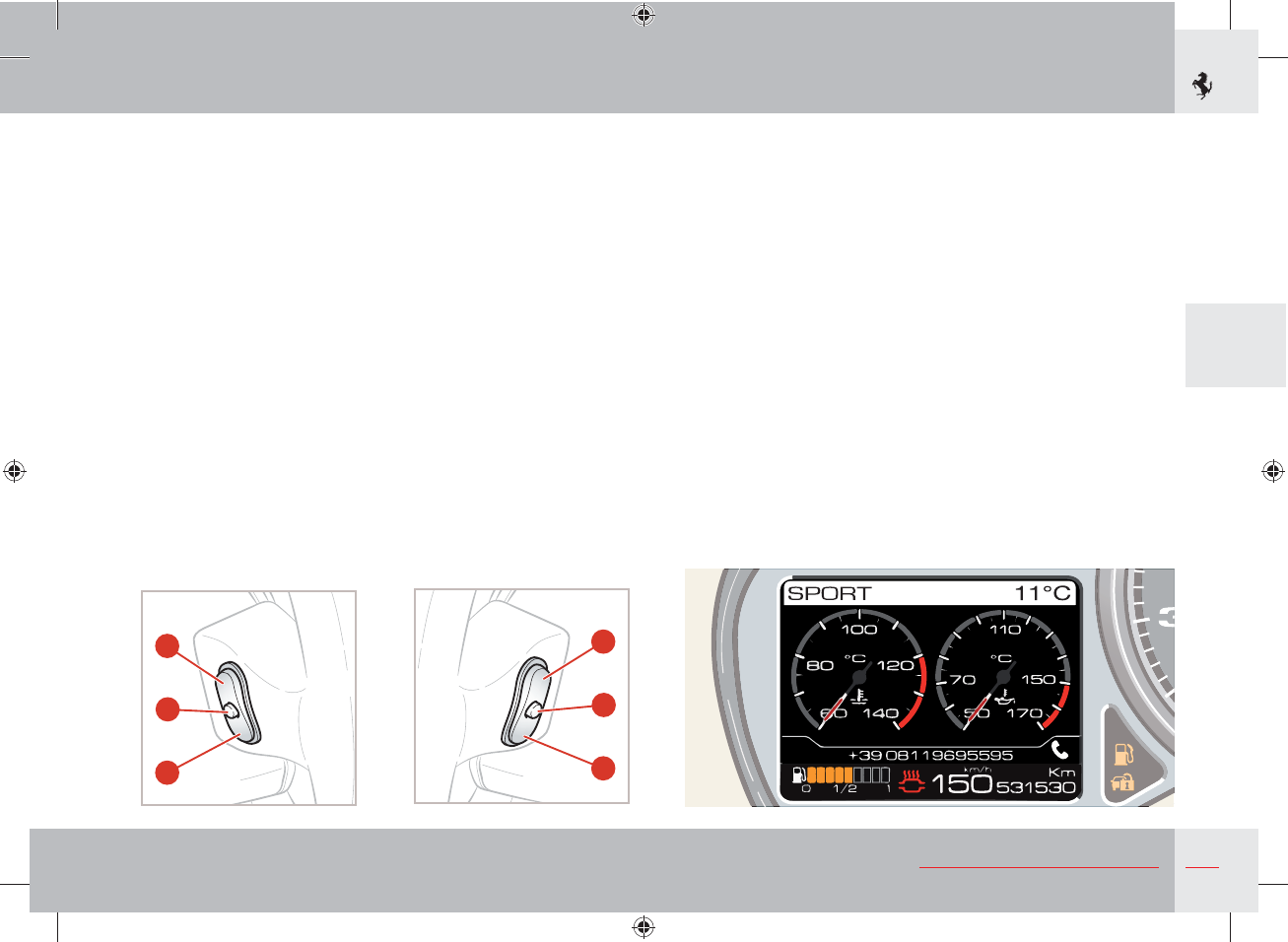
101
3
About your Vehicle
Controls on the steering wheel
As well as using the commands on both sides of the touchscreen
display, the infotainment system can be controlled using buttons
located on the back of the steering wheel as indicated by the
arrows in the figure.
Buttons A and B for volume control and button PTT C are on the
left-hand steering wheel spoke: press button A to increase the
volume and press button B to decrease it. Hold down button B to
mute the volume (MUTE function). To deactivate volume muting,
press button A.
Button C is used to activate the voice commands; if the voice
recognition function is already activated, it can be deactivated by
quickly pressing button C. If there is an incoming call, quickly press
button C to accept it or hold it down to refuse it.
The SCAN + D and SCAN - E buttons are on the right-hand
steering wheel spoke. They are used to scan the radio stations (if
RADIO mode is activated) or go to the next or previous track (if
MEDIA mode is activated). The SOURCE F button is used to select
the available sources (FM, MW, DAB, USB).
Repetition on display of infotainment system information
You can select whether to also display infotainment system
information on the TFT display in the instrument panel via the
MENU function on the TFT display.
If repetition is activated, the MEDIA information is displayed in
minimised form on the left of the TFT display whereas information
on the phone and navigation functions are displayed on the right.
To activate/deactivate repetition of infotainment system
information, call up the MENU screen page using the controls on
the dashboard to the left of the steering wheel, select “Display
setup” and then select either ON or OFF for repetition of audio
information.
A
C
B
D
F
E
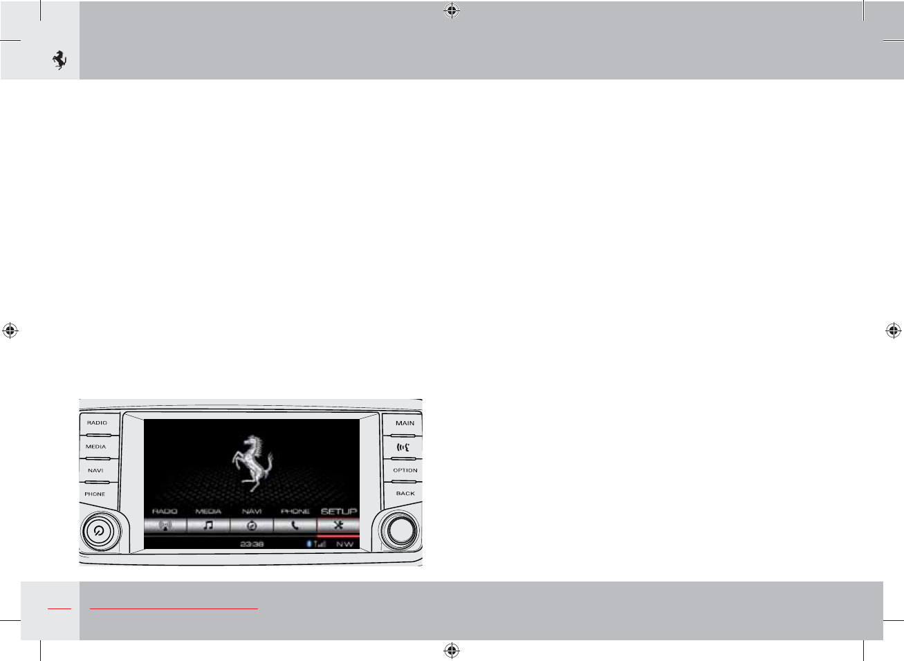
102 About your Vehicle
System settings
To access the system settings from the main screen, press the
OPTION button on the right of the display or the SETTINGS soft
key.
Audio control
Once you are in the SETTINGS menu, press the “Audio” soft key
to access the audio control menu. You can adjust the balance/
fading and equalisation of the stereo system, activate/deactivate
“Quantum Logic” (if present) and adjust the volume according to
the speed on this page.
To adjust the balance and fading, press the arrow soft keys.
The equalizer settings can be used to adjust the bass (BASS), mid
(MID) and treble (TREB) levels.
Press the “Quantum Logic” soft key to activate/deactivate the
option.
The volume can be adjusted to the speed on 3 levels or deactivated.
Adjusting display brightness
From the main screen, press the OPTION button on the right of
the display or the SETTINGS soft key and select “Display”. For set
the display brightness, select “Display Brightness” and set the day
and night brightness levels. In both cases, the brightness can be
adjusted by using the soft keys on the display.
In the Display settings menu, if “Auto Colour Mode” is selected, the
display automatically adopts daytime or nighttime mode depending
on the ambient light or how the vehicle light switch is set.
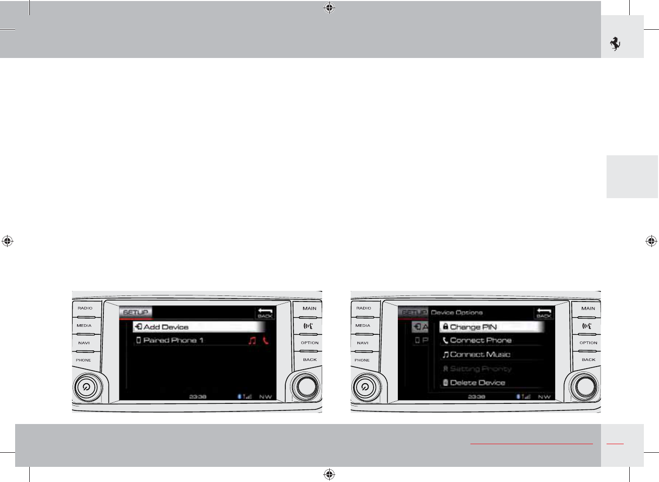
103
3
About your Vehicle
Pair a Bluetooth Phone/Audio device
From the main screen of the navigator, press the OPTION button
on the right of the display or the SETUP soft key and select
“Bluetooth Phone/Audio”. Press the “+ Add Device” soft key to pair
a new Bluetooth device (telephone, tablet, laptop, etc.).
The icons on the right showing a phone and music indicate to the
user the type of device connection and whether it is music only,
phone only or both.
After pairing and selecting a peripheral, press the “OPTION”
button on the right of the screen to access the Bluetooth device
settings. Here you can tell the system to give priority to the
peripheral selected using the “Setting Priority” option.
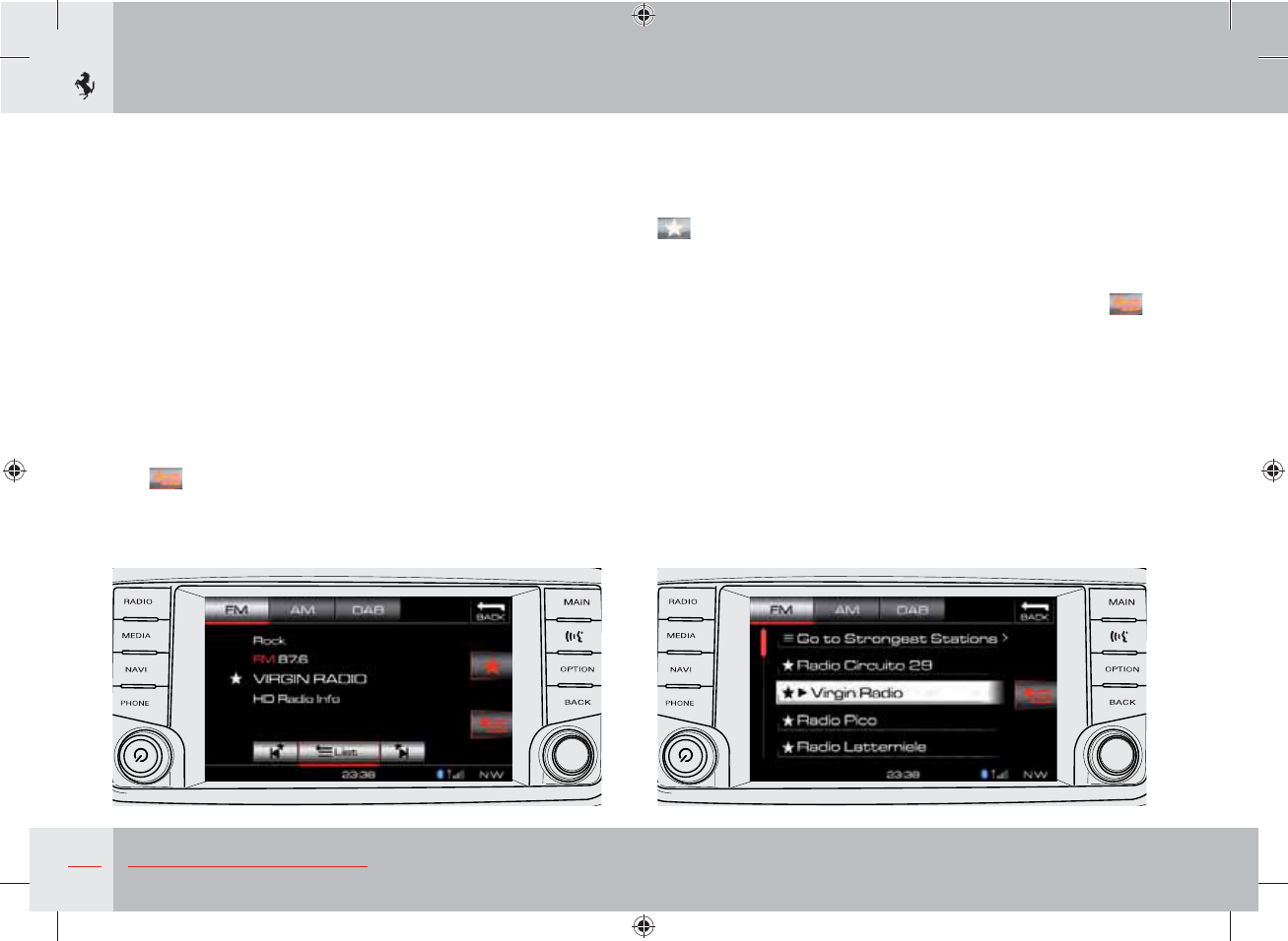
104 About your Vehicle
RADIO function
Press the RADIO button to the left of the display once to access the
correct mode. To switch between the FM, MW and DAB sections,
press the soft keys or press the RADIO button several times.
Selecting a radio station
Once you have selected the desired band, you can begin automatic
scanning of the radio stations by turning the right button or
manually enter the desired frequency by using the numeric keypad
which can be accessed from the Radio options menu (see
page 105). You can also select the desired radio station from a list
by pressing the “List” soft key. The list has two display options - the
first shows the radio stations stored as “Favourites” whereas the
second shows the radio stations with the strongest signal in the
area. To change display mode, press the “Go to favourites/Go to
strongest stations” soft key at the top of the list or use the Smart
Icon on the right of the screen.
Storing favourite radio stations
You can store your favourite radio stations for each frequency band.
To set a favourite radio station, find the station with the right
button or numeric keypad and press the Smart Icon showing a star
on the right of the screen.
Scanning favourite radio stations
To scan just your favourite radio stations, press the Smart Icon .
With this function activated, turn the Scroll Control to scan the
stations previously saved as favourites.
To display the list of stored stations, press the “List” soft key in the
bottom part of the display and select the “Go to favourites” display
mode.
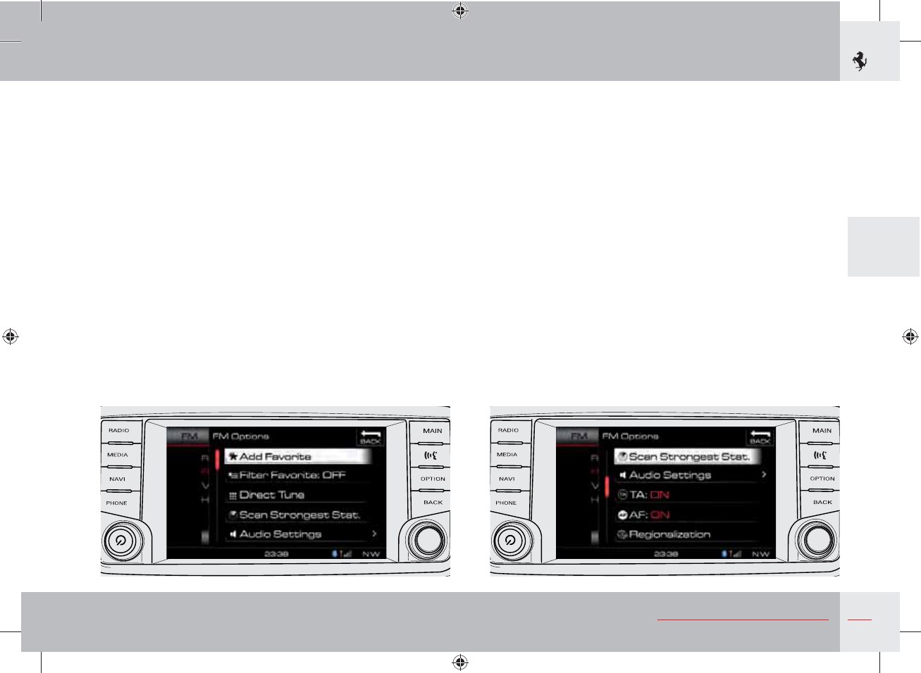
105
3
About your Vehicle
DAB radio
Digital radio has some additional options: artists/musical genres
can be indicated as favourites.
Radio settings
When you are in one of the three bands FM, MW or DAB, press the
OPTION button to the right of the display to access the settings
menu.
106 About your Vehicle
MEDIA function
Press the MEDIA button to the left of the display once to access
the correct mode. To switch between the DISC (if present),
BLUETOOTH and USB sections, press the soft keys or press the
MEDIA button several times.
Disc mode (DISC)
If the system has a CD player (optional), it is installed in the glove
compartment on the passenger side:
Important note
When placing a disc in the player slot, make sure the label is
facing upwards.
Insert the disc in the slot: the system pulls it into the player.
Once it has recognised the disc, the system selects the appropriate
mode and starts to play the first track.
Warning
The player only accepts 12 cm (4 ¾ inch) discs. Using discs of
any other format may damage the player mechanism.
The system can play compact discs (CD), recordable compact discs
(CD-R) and rewritable compact discs (CD-RW).
The system plays these formats: MP3, WMA, CD Audio.
Insert supported CD formats only.
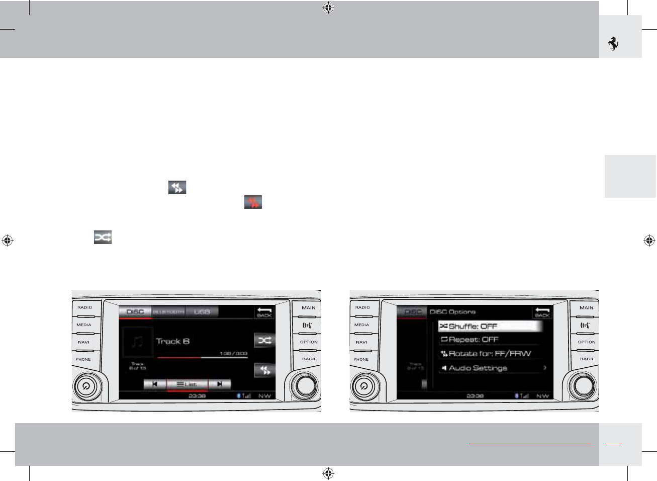
107
3
About your Vehicle
Playing a disc
After inserting a disc in the player, the system selects the
appropriate mode once it has recognised the disc and starts to play
the first track.
To go on to the next or previous track, you can use the right button
or buttons D and E behind the right-hand spoke of the steering
wheel.
To display and scroll through the list of multimedia content on the
CD, press the “List” soft key in the bottom of the display.
To fast forward or rewind a track, go to the desired mode by
pressing the “Smart Icon” on the right of the display and turn
the right button and re-press the “Smart Icon” so that the
right button goes back to the previous function (go to beginning/
end). To activate the “Shuffle” play mode, press the relative “Smart
Icon” .
Disc mode settings
While you are in disc mode with a disc inserted, press the OPTION
button to the right of the display to access the options menu. Here
you can activate/deactivate the “Shuffle” mode, activate/deactivate
the “Repeat” mode, select the right button operating mode (FF/
FRW or go to beginning/go to end) and access the “Audio
Settings”.
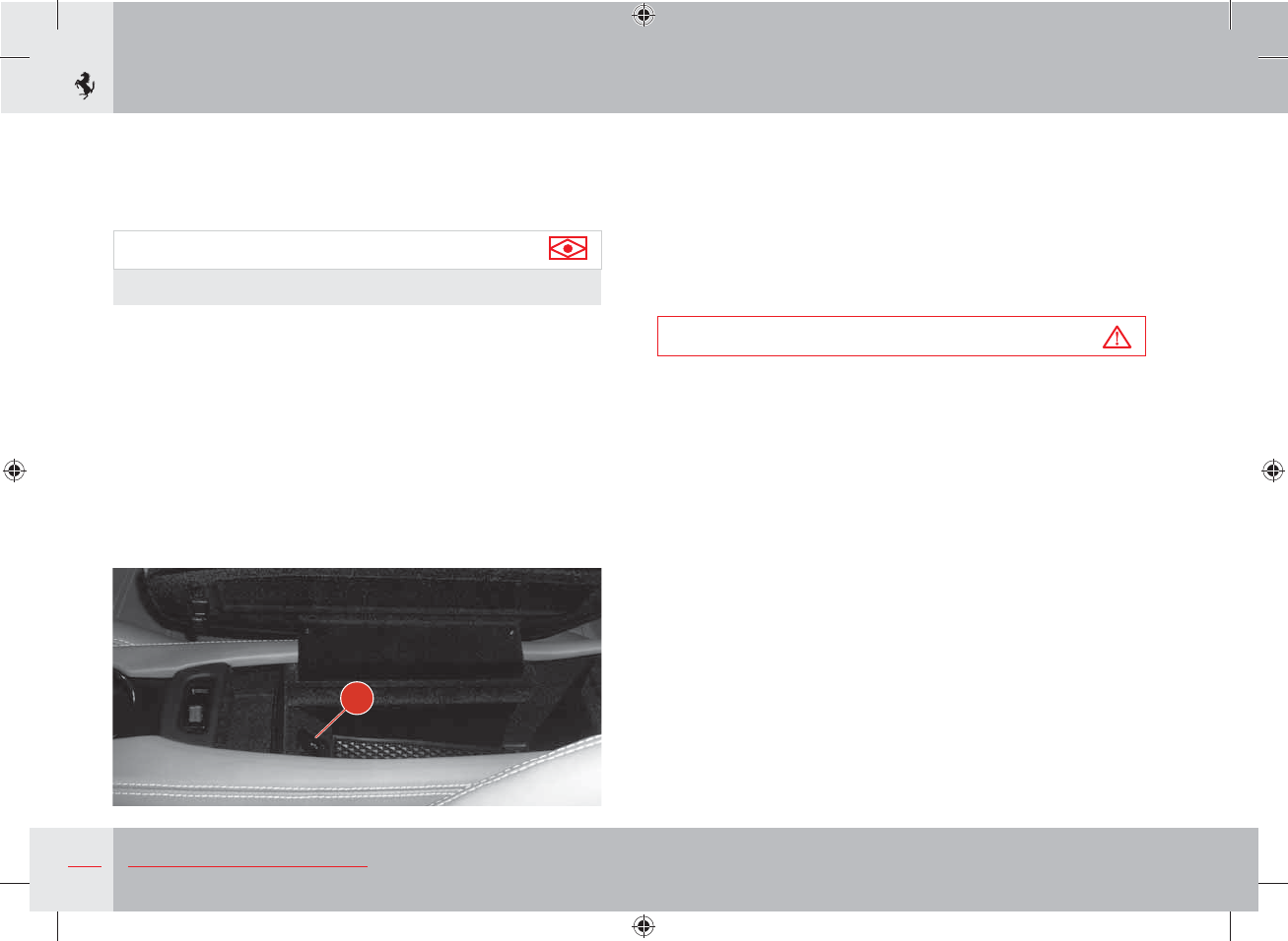
108 About your Vehicle
Bluetooth mode
In Bluetooth mode, you can play audio files stored on external
devices. These can be connected to the system via the Bluetooth
connection once the device has been paired (see page 103).
Important note
The “List” function cannot be used in Bluetooth mode.
Bluetooth mode settings
While you are in Bluetooth mode with a paired peripheral, press
the OPTION button to the right of the display to access the options
menu. Here you can activate/deactivate the “Shuffle” mode, activate
the “Repeat” mode, access the Bluetooth device settings and access
the “Audio Settings”.
USB mode
The USB mode provides access to the files in the USB peripheral
connected to the system via connector A in the pocket change
compartment on the centre console.
USB connection
Using the USB connector, you can also play audio files from iPod®
and iPhone® devices, using the USB cable supplied with the device.
Warning
Do not force connectors into the infotainment system ports.
Before connecting, make sure that the connectors are the same
shape and size as the port.
Playing multimedia content is the same as the disc mode. See
page 106.
USB mode settings
While you are in USB mode with a USB peripheral connected to
the system, press the OPTION button to the right of the display
to access the options menu. Here you can activate/deactivate the
“Shuffle” mode, activate/deactivate the “Repeat” mode, select the
right button operating mode (FF/FRW or go to previous track/next
track) and access the “Audio Settings”.
A
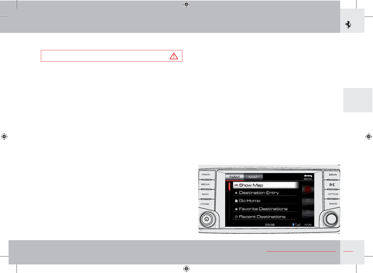
109
3
About your Vehicle
Navigation function (NAV)
Warning
Drive carefully, keep your eyes on the road and comply with
road regulations.
Press the NAVI button to the left of the display to go to Navigation
mode.
Press the NAVI button again to switch from the main “Navi” screen
to the Map and vice versa.
When the main “Navi” screen is displayed on the right of the
display, “Smart Icons” appear which can be used to rapidly access
several navigation options:
- STOP
This stops navigation.
- Detour
This is used to select a detour/alternative route.
- Repeat
This repeats the last voice command.
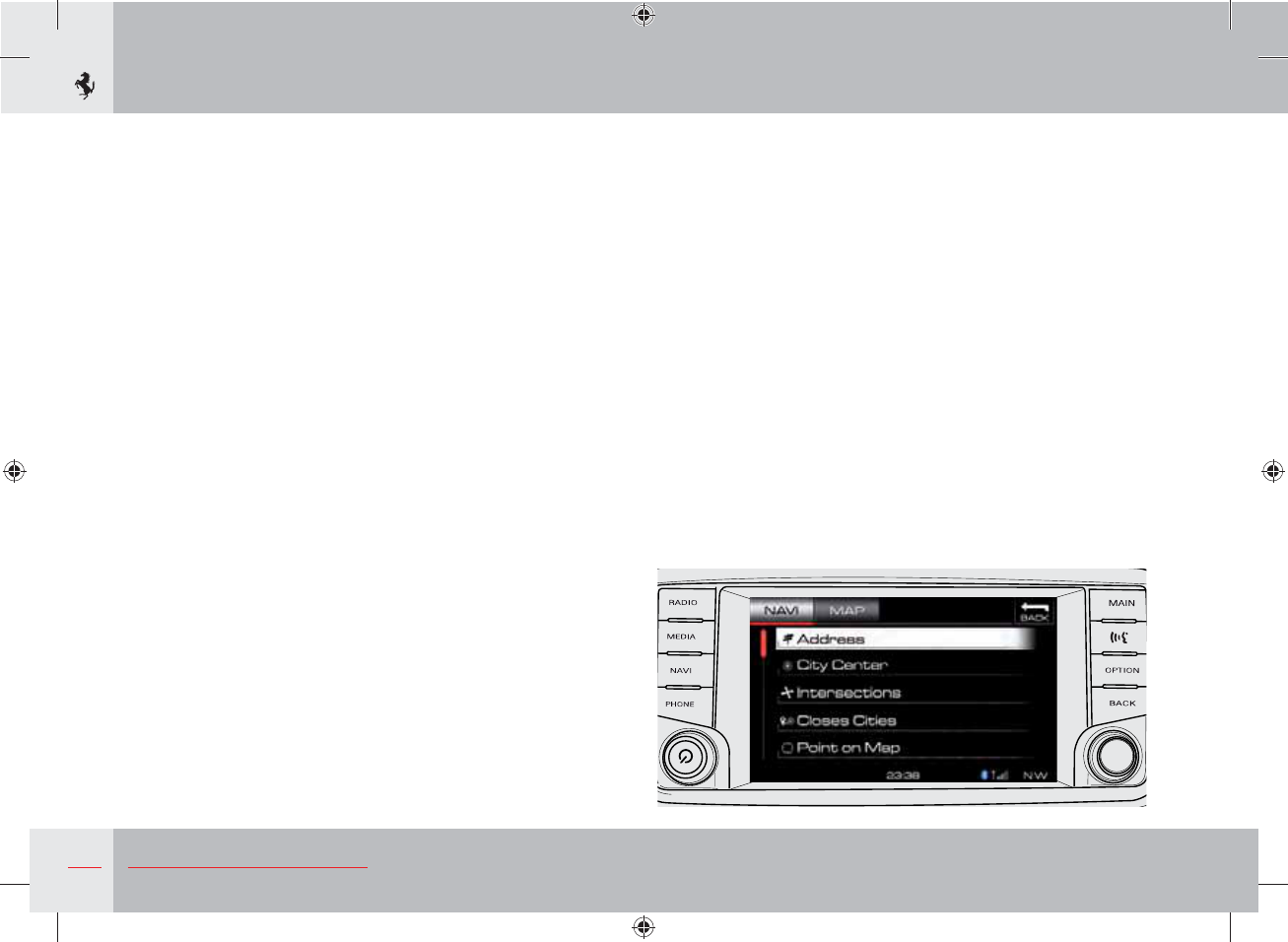
110 About your Vehicle
Main Navi menu
The main NAVI menu has the following menu items:
- Show Map
Press the “Show Map” soft key to display a map of the current
position. See the “Show Map” section for details.
- Destination Entry
Press the “Destination Entry” soft key to plan your destination.
- Go Home
Press the “Go Home” soft key to follow the route to the preset
“Home” position.
- Favourites
Press the “Favourites” soft key to enter a point of interest from a
list of preselected favourite places, also available when the vehicle
is moving.
- Recent Destinations
Press the “Recent Destinations” soft key to call up a recent
destination.
- POI (Point of Interest)
Press the “Point of Interest” soft key to select a destination from the
list of positions, public places or points of interest. Search by name,
telephone number, category or type of place.
- Emergency
Press the “Emergency Info” soft key to follow the route to an
emergency service near the current position of the vehicle. This
includes the fire brigade, police, hospitals.
- Trips
Press the “My Trips” soft key to enter a point of interest from a
previously saved list of itineraries.
- Where Am I Now
Press the “Where Am I Now” soft key to find your current position.
Destination entry using an address
Press the “Destination Entry” soft key on the display to display the
available options.
To enter the destination by manually entering the address, press
the “Address” soft key. You can also head for a “City Centre”,
“Intersections” or choose a city from the list of “Closest Cities”.
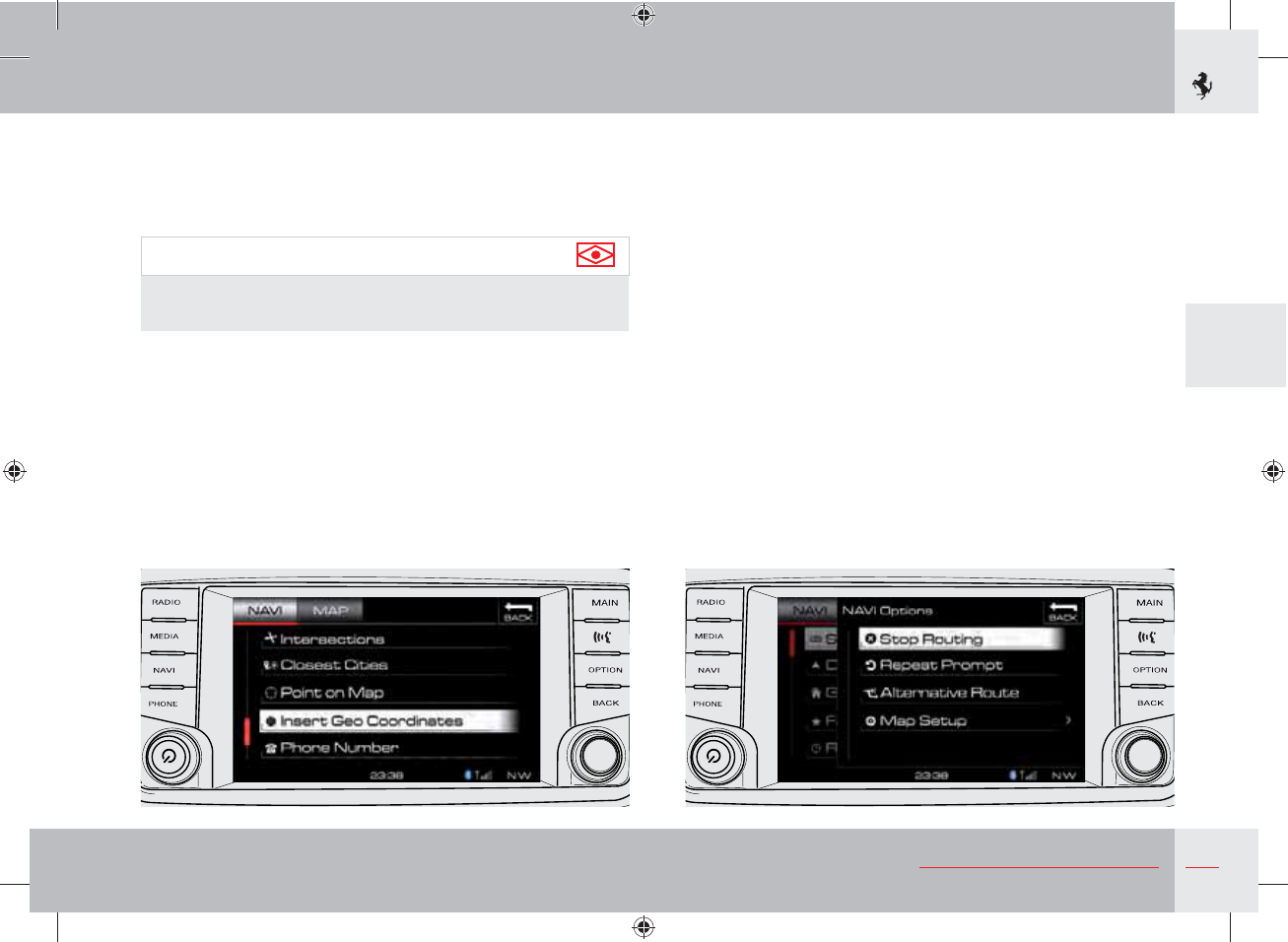
111
3
About your Vehicle
Alternatively, you can enter the destination by selecting a point on
the map or entering the coordinates or phone number.
Once you have pressed the “Address” key, you are asked to enter
the Country, City, Post Code and Address.
Important note
For safety reasons, you cannot use the keyboard to enter a name
when the vehicle is in motion.
As you type in the name, the number of possible roads decreases.
Once you have selected the road, enter the number.
If you press “Skip” the number is not entered and the navigator
takes you to the part of the street nearest to the current position.
The planned route can be interrupted at any time by pressing the
“STOP” Smart Icon in the main NAVI menu.
Navigation options
To access the Navigator options, go to the main NAVI screen, press
the button on the right of the “OPTION” display and select “NAVI
Options” from the display menu.
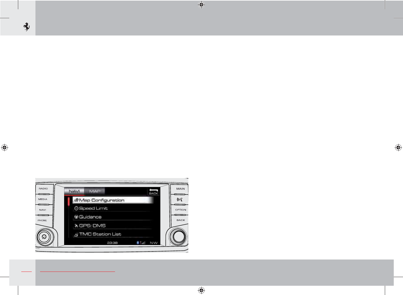
112 About your Vehicle
The navigation options can be used to access the following sections:
- Map Configuration.
- Speed Limit.
- Guidance (driving options while navigating).
- GPS.
- TMC Station List (traffic information).
- Preset Route.
- Cancel all Destinations.
- Cancel Home Address.
MAP settings
Once the planned route has started, from the MAP section you can
change some of the navigation settings by pressing the “OPTION”
soft key on the right of the display.
- Map: 3D/2D
This is used to select the map display mode.
- Rotate for Zoom
This is used to select whether to assign the zoom function to the
SCROLL CONTROL during map display.
- Stop Navigation
This stops navigation.
- Repeat Prompt
This gets the system to repeat the last navigation voice command.
- Divert
This plans a different route by taking a detour from the current
route: the navigator displays a list of the possible detours to choose
from.
- Complete Route
This displays the complete route on the map.
- Hide POI
- Turns
- Where Am I Now
- NAVI Options (see page 111).
- Traffic Events
This displays a list of traffic events for the set route.
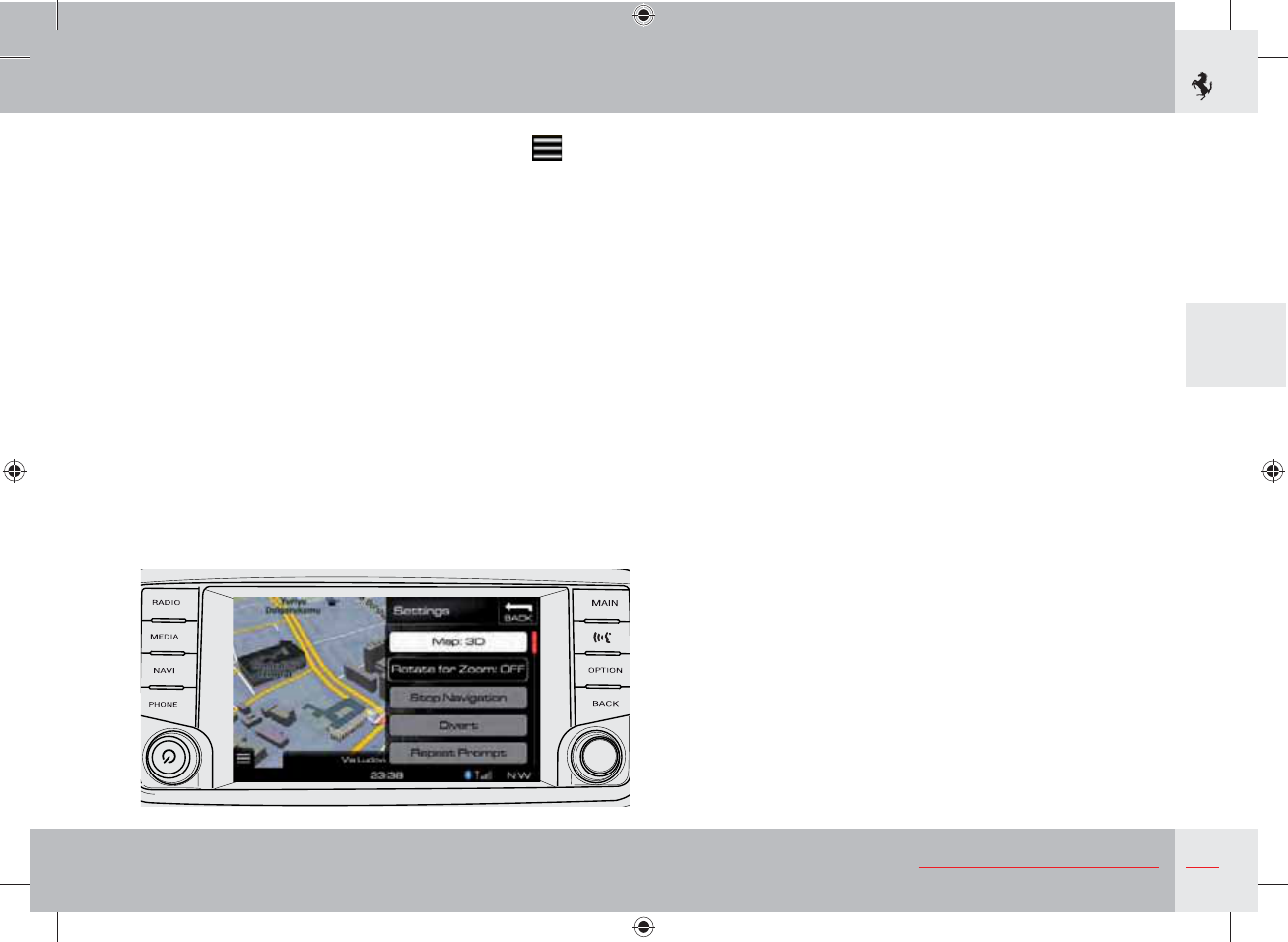
113
3
About your Vehicle
To go back to the main Navi screen, press the soft key
displayed in the bottom left of the display or press the NAVI button
on the left of the display.
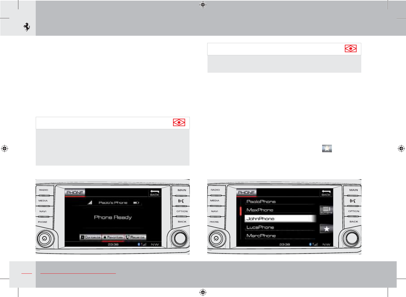
114 About your Vehicle
Telephone function
The telephone function is a hands-free in-vehicle communications
system that allows you to dial a phone number with your mobile
phone by using simple commands or the soft keyboard that appears
on the display.
Your phone's audio is transmitted via the vehicle audio system;
when the telephone function is used, the infotainment system
automatically mutes the car radio.
To use the telephone function, you must first of all pair a Bluetooth-
compatible mobile phone (see page 103).
Important note
2 phones can be connected to the system, one with the “Phone”
function and one with the “Audio streaming” function (playing
of music). A phone which has been assigned the “Audio
streaming” function cannot be used for the “Phone” function
and vice versa.
Important note
For an up-to-date list of compatible phones, contact the Ferrari
Service Network.
Press the PHONE button to the left of the display to go to
Navigation mode.
Three soft keys are displayed in the bottom of the display which
can be used to access the functions: Contacts, Favourites and
Recents.
Contacts
Press the “Contacts” soft key to access the paired phone's address
book. A “Smart Icon” appears on the right that can be used to sort
and/or display the list by name or surname. A contact can be
assigned as a favourite by pressing the Smart Icon .
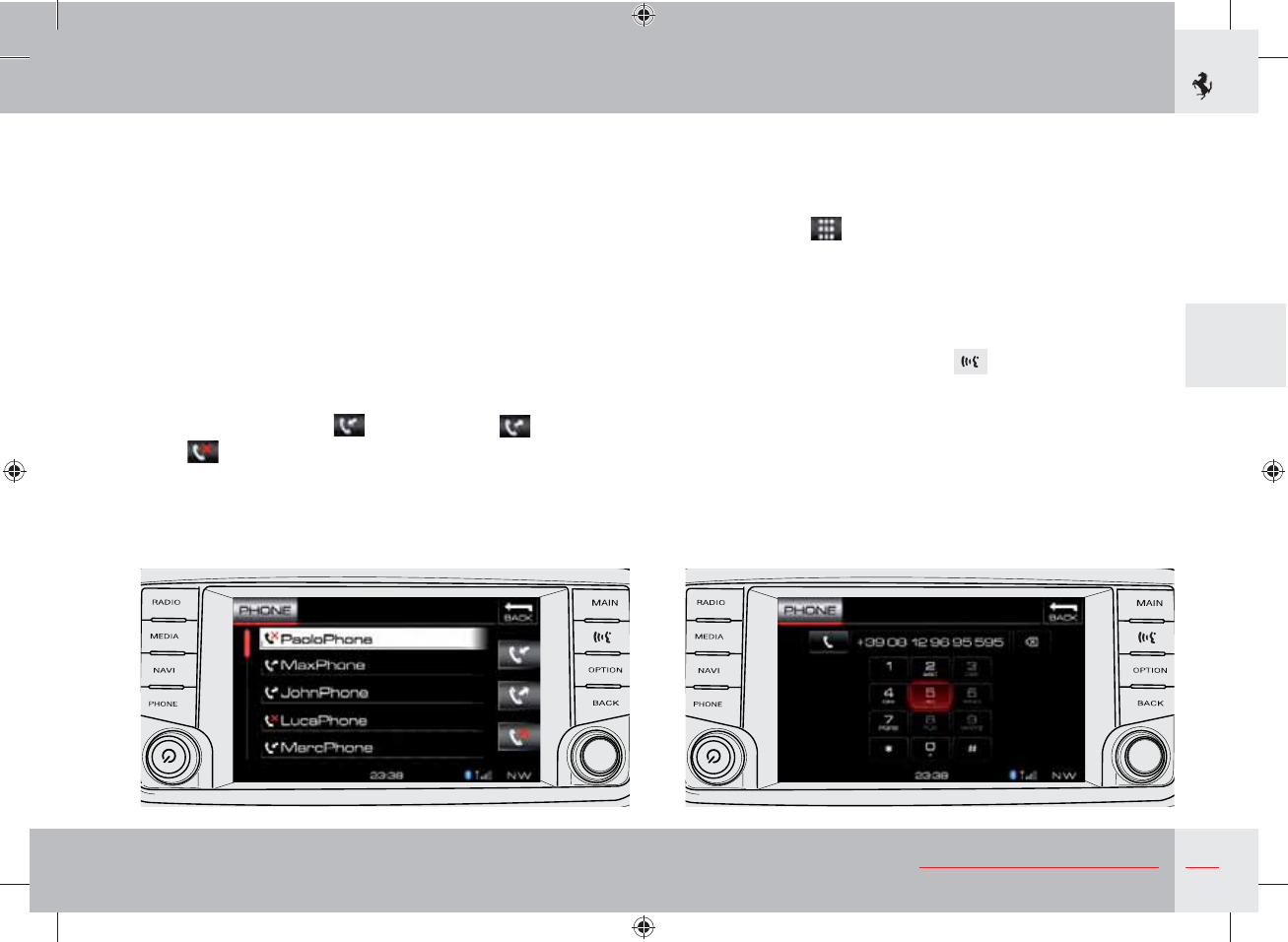
115
3
About your Vehicle
Search
You can search for a contact by entering his or her name in the
“Search” field above the contact list.
Favourites
From the main “Phone” screen press the “Favourites” soft key to
access the list of favourite numbers which have been previously
saved from the “Contacts” list.
Recents
Press the “Recents” soft key to access the list of numbers used
recently.
Three “Smart Icons” appear on the right which can be used to
filter the “Incoming Calls” , “Outgoing Calls” and “Missed
Calls” .
Making a call
To make a call, you can select a contact from the “Contacts”,
“Favourites” or “Recents” lists or manually enter the phone number
using the soft keyboard that appears on the display;to redial, use
the “Smart Icon”
y
y
y
y
y
displayed on the main “Phone” screen.
PTT function
The Push To Talk function is a hands-free in-vehicle
communications system that allows you to navigate the system by
using simple voice commands.
To call up this function, press button to the right of the screen.
If you give the voice command “Guidance”, the system reads out a
list of voice commands for the displayed screen.
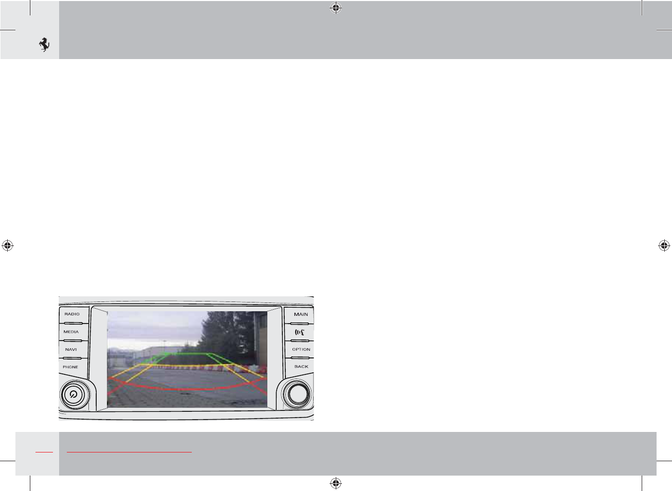
116 About your Vehicle
Parking Camera function (optional)
“Rear Parking Camera” screen (optional)
If the vehicle has a rear parking camera (optional), the “Rear
Parking Camera” screen is automatically displayed on the
infotainment system display when rear gear is engaged. This screen,
which is displayed as long as the vehicle is in reverse gear, shows
the view range of the camera mounted on the rear bumper and
helps the driver when parking.
With reverse gear engaged, press button C on the dashboard to
switch between:
- rear view with grids;
- rear view with wide angle lens.
The image is integrated with dynamic parking grids in green, yellow
and red which, based on the steering angle, estimate and indicate
the vehicle's path to the driver during the manoeuvre.
The dynamic parking grids also indicate the distance from any
obstacles in the camera's view range: the area within the red grid
represents an area that ranges from 0 to 60 cm, the yellow one from
60 to 120 cm and the green one from 120 to 240 cm.
To exit the “Rear Parking Camera” mode and go back to the
infotainment system screen, hold down button C for a few seconds
or disengage reverse gear if it is engaged.
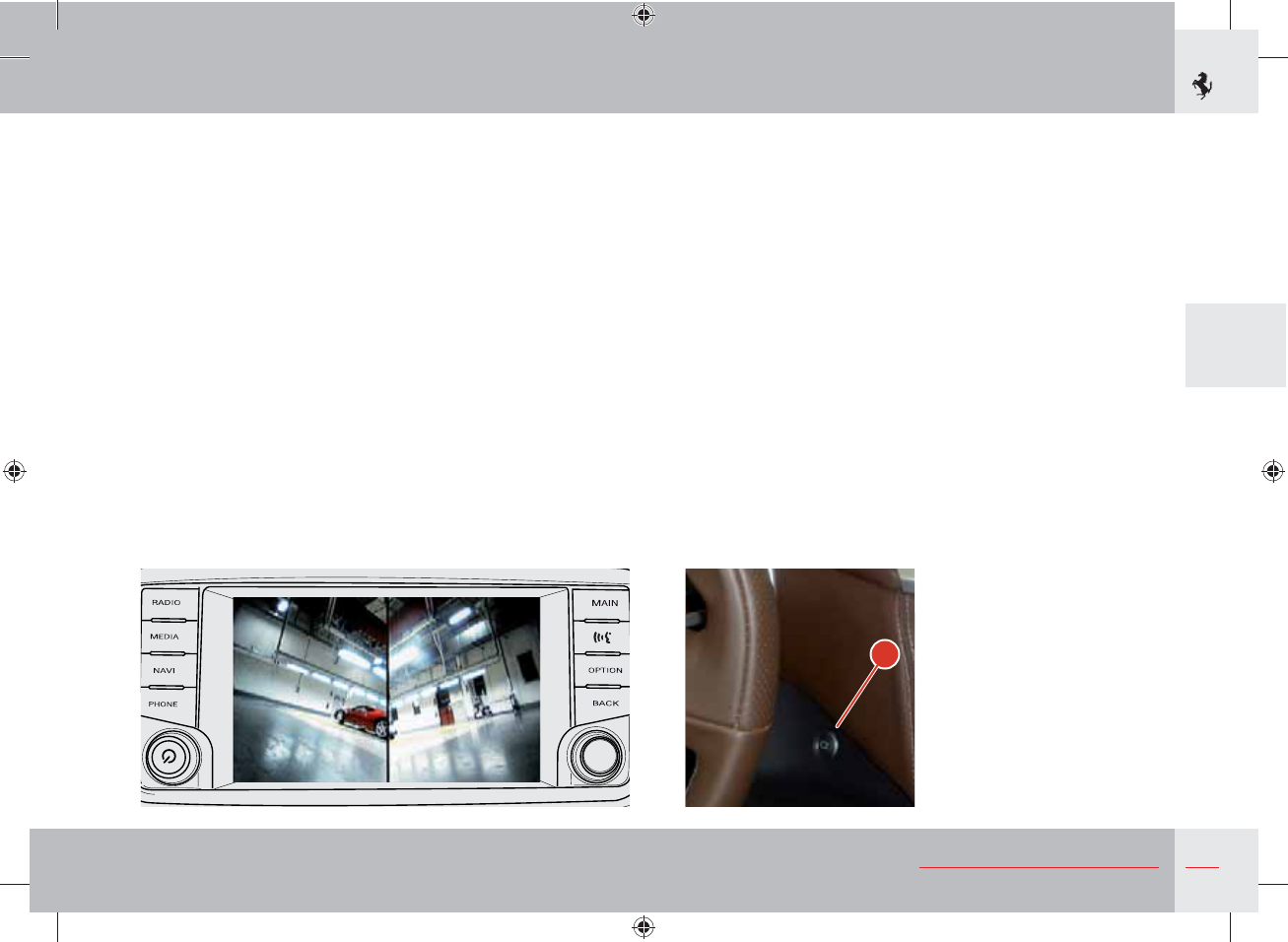
117
3
About your Vehicle
“Dual View Camera” screen (optional)
If the vehicle has a “Dual View Camera” system consisting of
another camera mounted in the front bumper as well as a rear
parking camera, the following views appear on the display:
- front lateral “Corner View”;
- central front “Top View”;
- rear view with grids (with Rear Parking Camera);
- rear view with wide angle lens (with Rear Parking Camera).
When reverse gear is engaged, the “Rear Parking Camera” screen is
automatically displayed on the infotainment system display.
Without engaging reverse gear, you can switch to the “Corner
View” mode (front camera) by pressing and quickly releasing
button C on the dashboard to the right of the steering wheel.
The view can be selected by pressing button C: press and quickly
release button C to call up the “Corner View”. Press the button
again to switch from one view to another.
The front camera image display is disabled if the vehicle exceeds a
speed of 12 km/h.
To exit the “Dual View Camera” mode and go back to the
infotainment system screen, hold down button C for a few seconds.
If one of the two rear views is displayed when reverse gear is
engaged, the system switches to displaying the “Corner View”
screen as soon as reverse gear is disengaged.
C
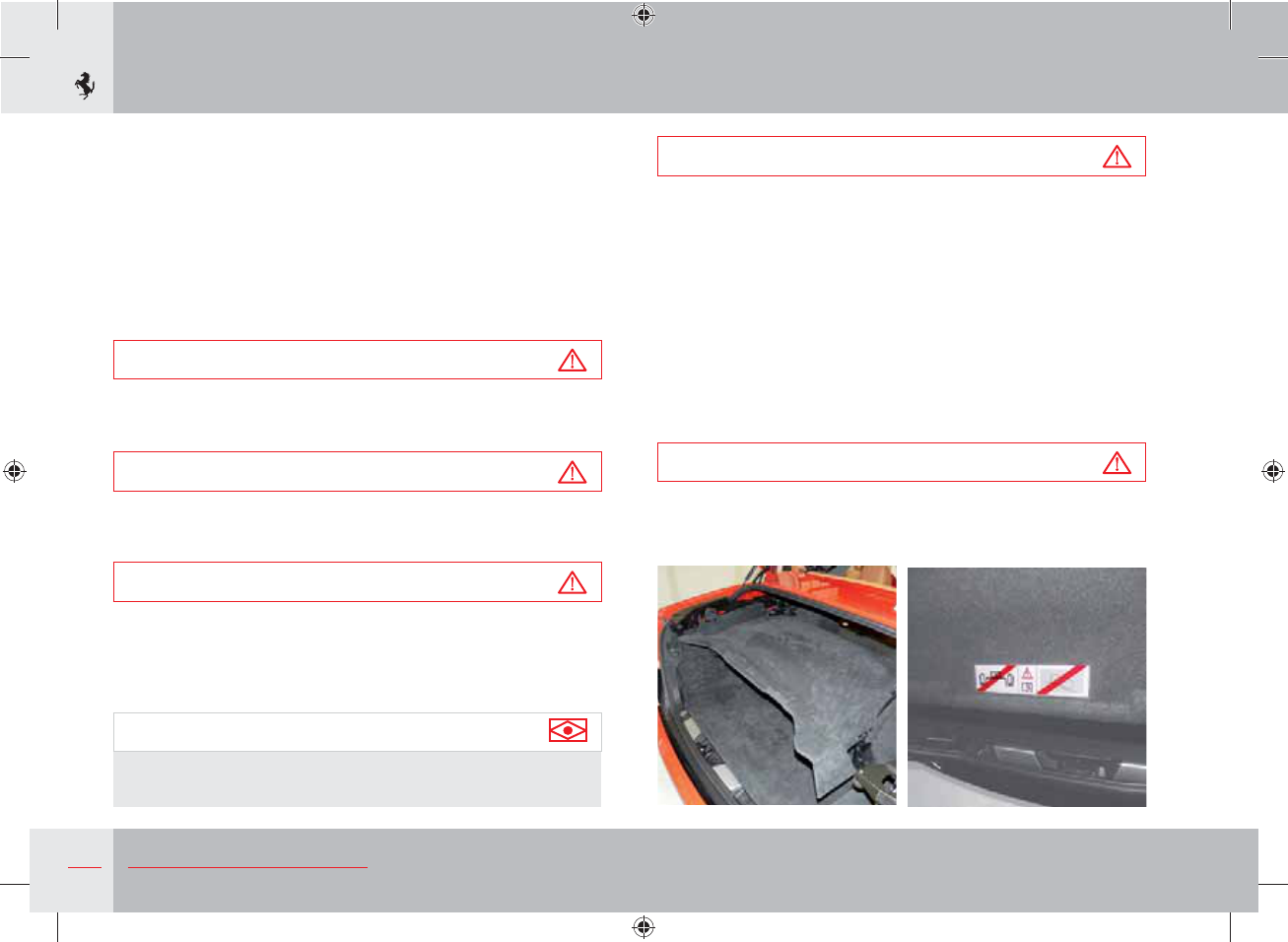
118 About your Vehicle
Retractable hard top
The hard top system is composed of three main moving parts:
- top section;
- rear section with rear window;
- luggage compartment lid.
Opening and closing is actuated by a hydraulic system, driven by
a pump and controlled by a number of sensors that check every
opening and closing phase.
Warning
For safety reasons, the retractable hard top can only be opened
and closed when the vehicle is stationary.
Warning
The roof must be opened or closed while remaining correctly
seated in the driver's seat.
Warning
Before activating the roof and while it is in motion, always check
that people and objects are at a safe distance from the moving
parts of the roof. In the event of danger, release the roof switch;
all movement will stop immediately.
Important note
Before opening or closing the hard top, refer to the “Placing
suitcases in the luggage compartment” section on page 205.
Warning
Before operating the retractable hard top, make sure that the
backrest of the child restraint system is set to its minimum height.
The conditions required for opening and closing the retractable
hard top are the following:
- the vehicle must be stationary;
- the luggage compartment must be closed;
- the battery voltage must not be below 11 volts;
- the partition between the luggage compartment and the folded
roof compartment must be in the correct position, fully pushed
back and fastened;
Warning
Do not place items above the partition! Risk of serious damage
to opening and closing mechanisms.
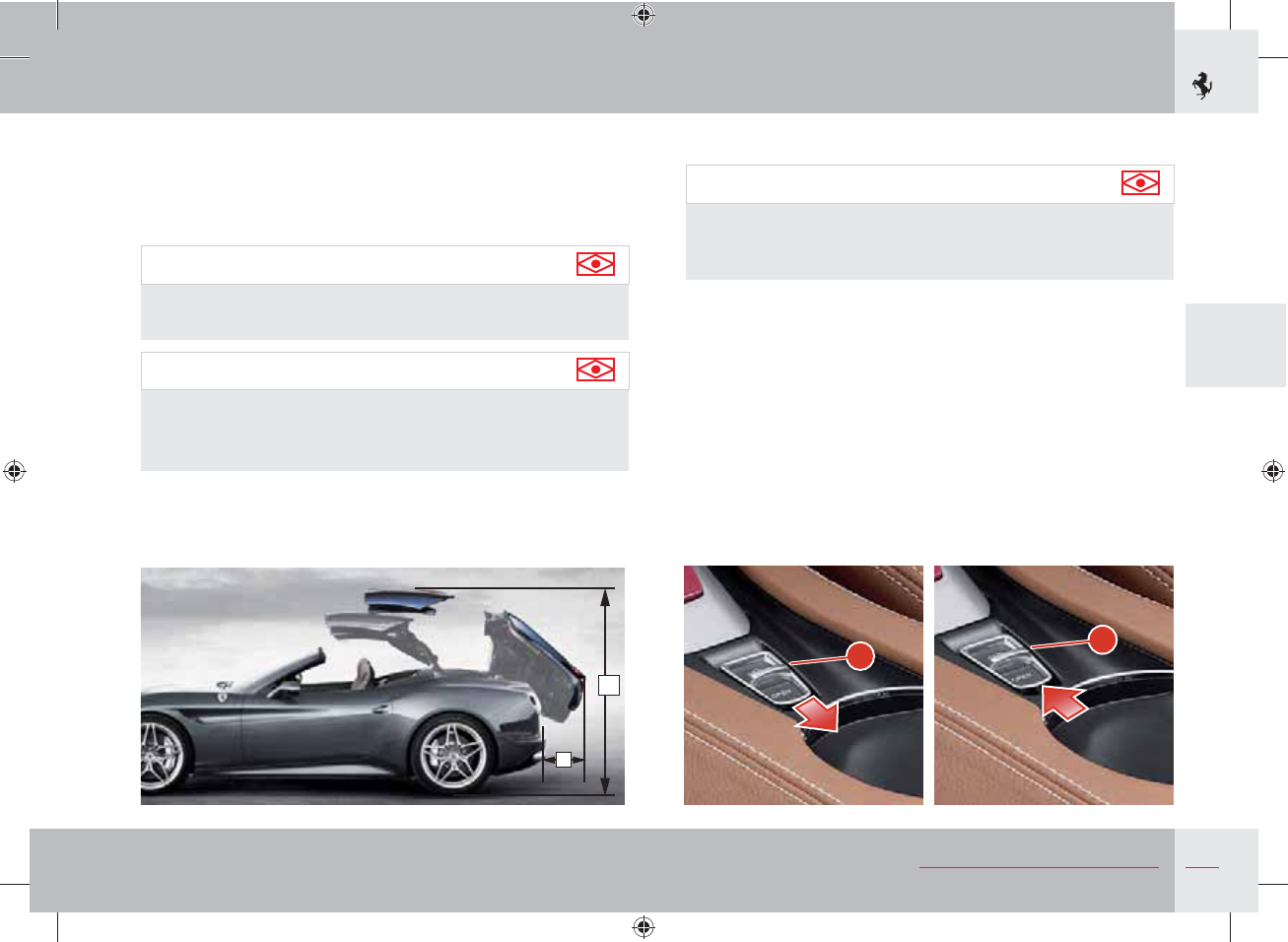
119
3
About your Vehicle
A
B
Roof opening using the switch
Important note
Before opening the roof, ensure that the top of the roof and
the rear window are dry to prevent water from entering the
passenger compartment or luggage compartment.
Pull back switch A on the centre console and hold until the roof is
completely open.
The operation in progress will be indicated by a warning on the
TFT display.
When the button is pressed, a series of operations required to open
or close the retractable hard top begins:
- the side windows are lowered completely;
- the rear window is raised;
- the luggage compartment lid rotates around a hinge fitted in its
rear part;
- check there is adequate space heightwise and in the rear of the
vehicle: the minimum available height A must be 1700 mm, the
minimum distance B of an obstacle from the rear must be more
than 400 mm;
- the ignition key must be in position II and the engine running;
Important note
We recommend operating the retractable hard top with the
engine running.
Important note
If distance B is less than 400 mm, the parking sensors will not
allow the roof to open or close.
The parking sensors are only activated when the key is in position II.
- the hydraulic system must not be overheated.
If one or more conditions are not met, the relevant message will
appear on the TFT display.
A
A
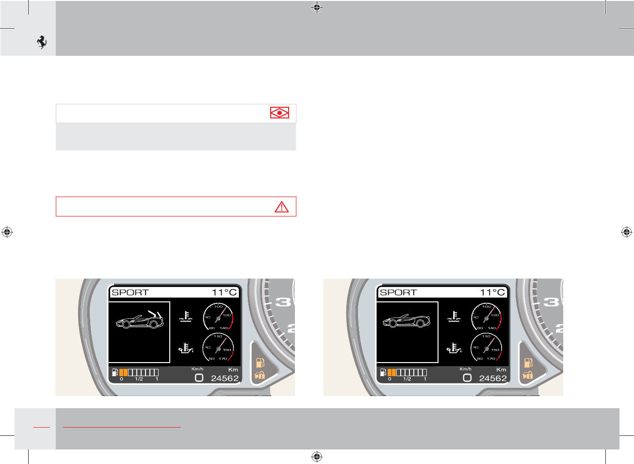
120 About your Vehicle
oof open
pe
Roof closing using the switch
Push switch A on the centre console forward and hold it until the
roof is completely closed.
The operation in progress will be indicated by a warning on the
TFT display.
When the button is pressed, a series of operations required to open
or close the retractable hard top begins:
- the side windows are lowered completely;
- the luggage compartment lid lifts and rotates backwards;
- the top section of the roof comes out of the luggage compartment
and rests on the edge of the windscreen bay;
- the luggage compartment lid completes the closing phase;
- the rear window starts moving back and goes into position.
Once the operation has been completed, an acoustic signal indicates
that the switch can be released.
- the rear window and luggage compartment lid parts are
positioned in the luggage compartment;
- the luggage compartment lid is closed.
Important note
Throughout all these phases, the side windows cannot be
activated.
At the end of the opening cycle, an acoustic signal will indicate the
end of the operations and the relative phase will be indicated with
a message on the TFT display.
Warning
Do not reverse the opening or closing direction when opening
or closing the roof.
Always complete the cycle until the acoustic signal is emitted.
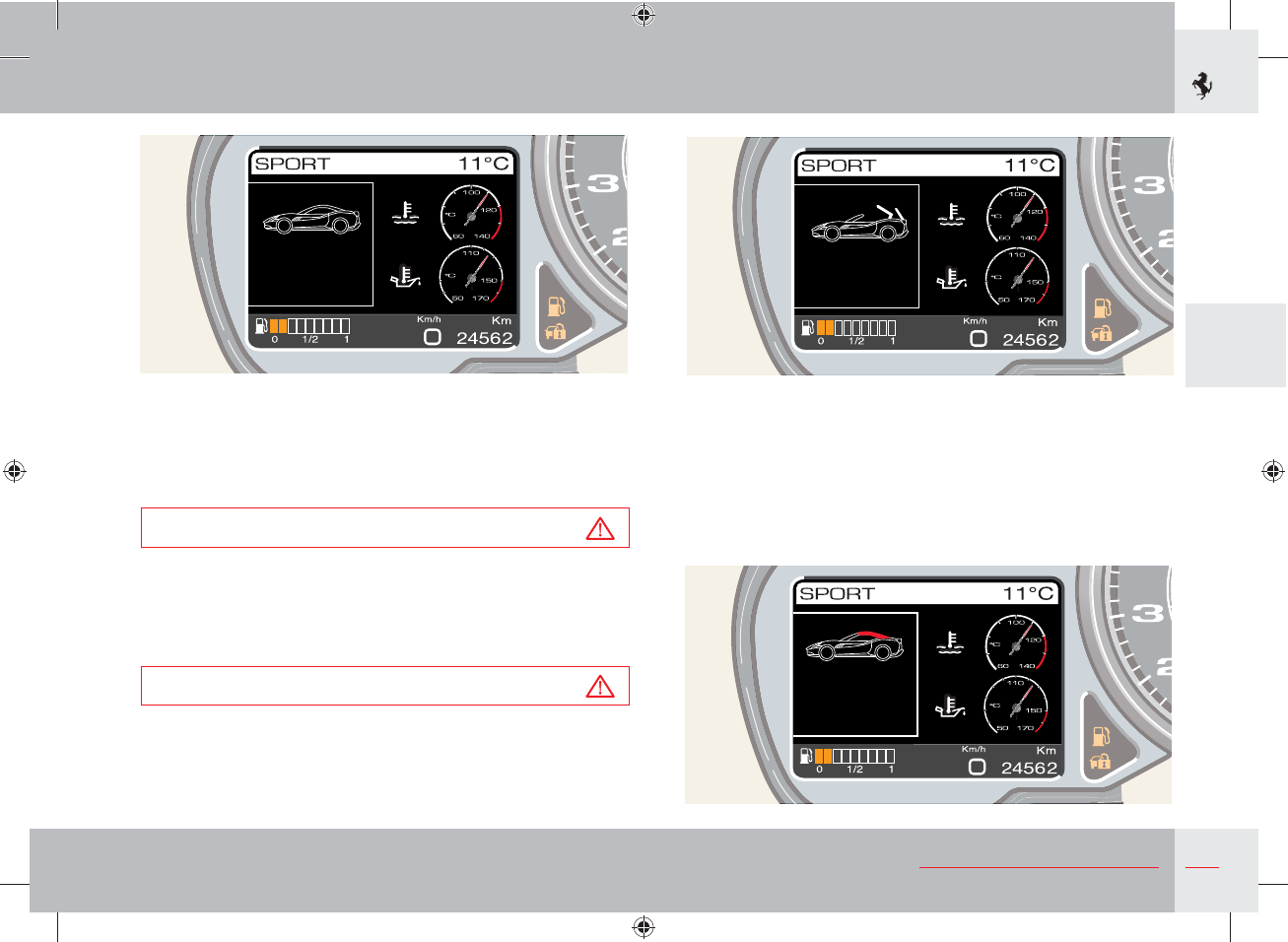
121
3
About your Vehicle
oof closed C p ete
r cyc e
per t
hte
tp cr r
r per t
Operation on stand-by
If the button is released before the retractable hard top has been
completely opened or closed, a message will appear on the TFT
display and will remain displayed until the opening or closing cycle
is reactivated.
Warning
Do not drive until opening or closing has been fully completed.
A few minutes after the roof is in standby position, an acoustic
signal and message on the TFT display will prompt you to complete
the operation.
Warning
Avoid interrupting opening and closing of the retractable hard
top. If the procedure has to be interrupted, you must avoid
leaving the hard top in a stand-by position for more than 4
minutes.
Operations not allowed
If the conditions for opening or closing the retractable hard top are
not met, this will be indicated by an acoustic signal and a message
on the TFT display:
- roof activation during vehicle motion;
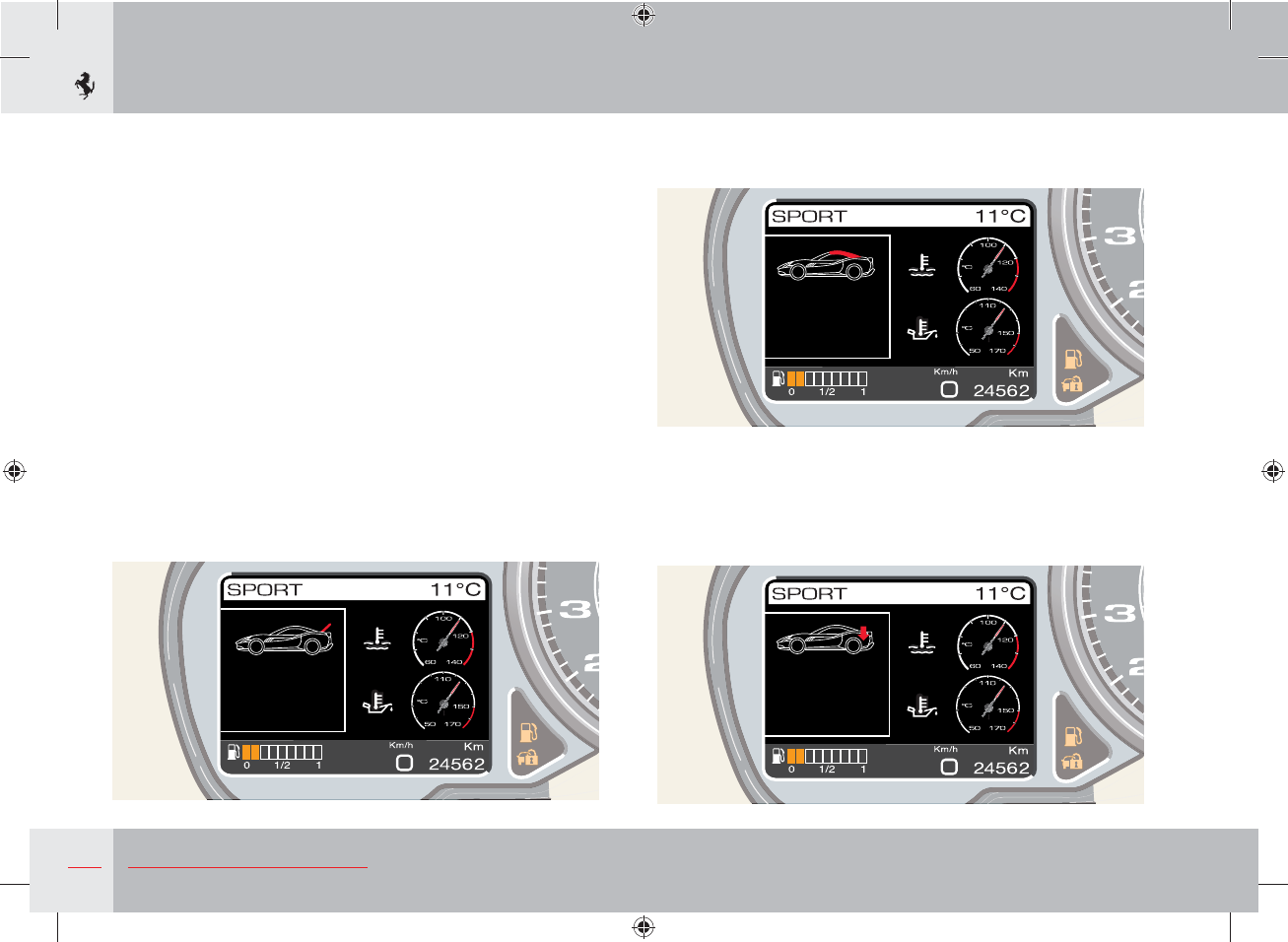
122 About your Vehicle
oof operation
inhi ited
Close l ggage
separator
per t
hte
ttery r
r per t
per t
hte
C se tru k r
r per t
- the partition between the luggage compartment and the folded
roof compartment must be in the correct position, fully pushed
back and fastened;
- the speed signal transmitted via the CAN network is not detected
by the ECU;
- the luggage compartment has not been closed correctly;
- the battery voltage is below 11 volts;
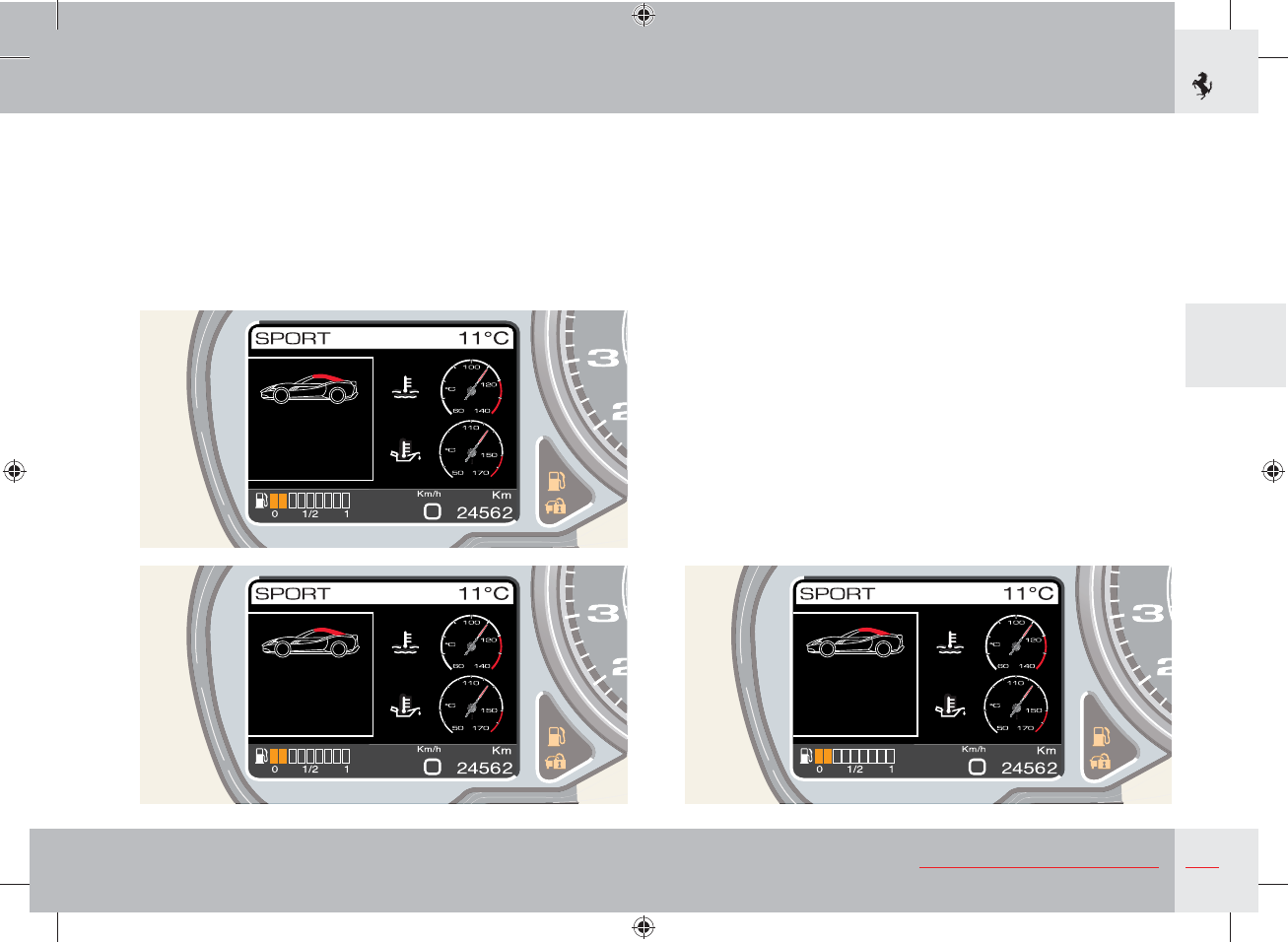
123
3
About your Vehicle
oof operation
inhi ited
ystem
o erheating
per t
hte
s
ure
per t
hte
st c e
etecte
- the hydraulic system is overheated;
- the window position sensor detects that at least one of the
windows is not in the correct position;
- the parking sensors have detected an object in the rear of the
vehicle;
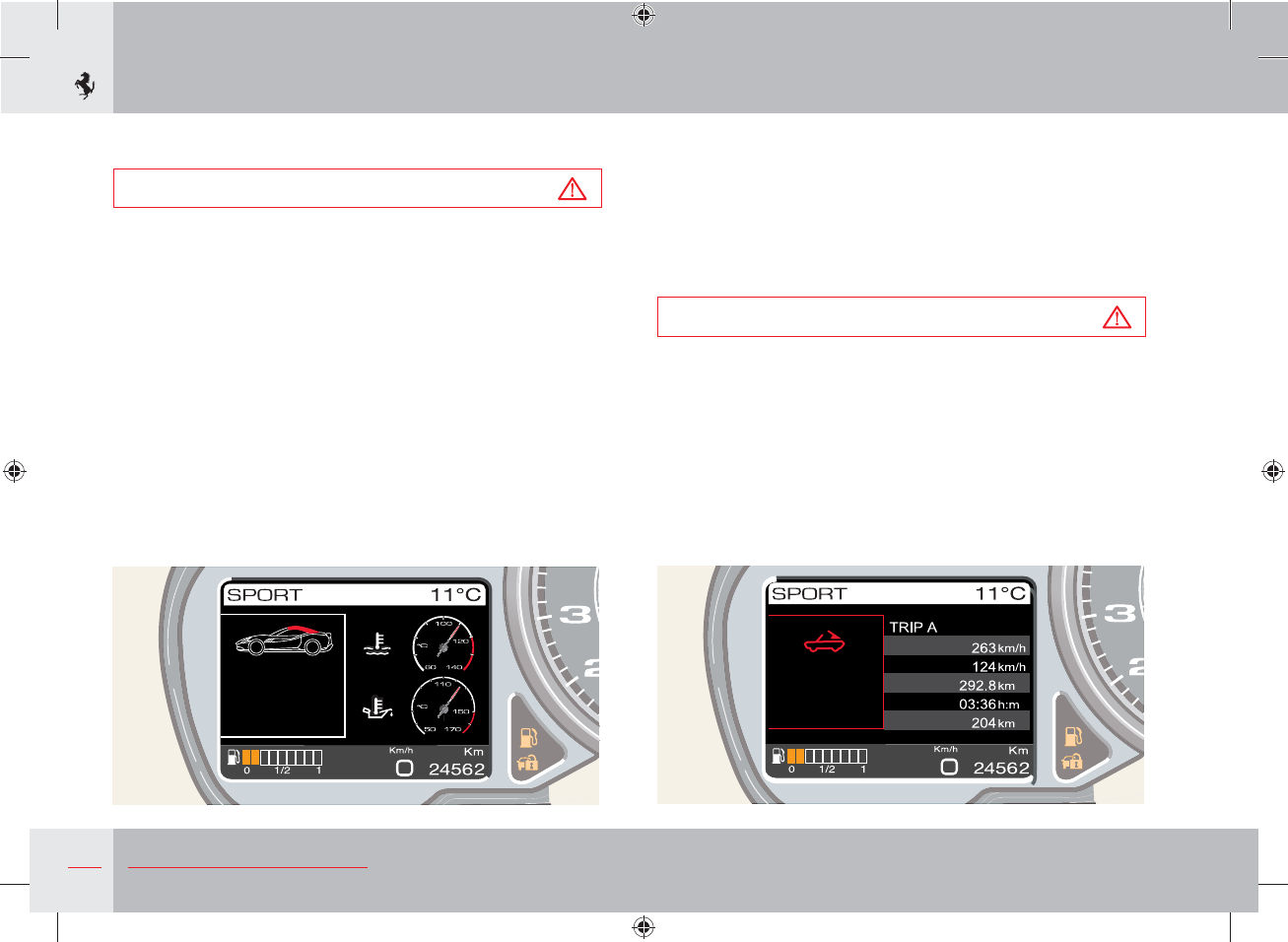
124 About your Vehicle
a speed
g speed
istance
rip time
ange
oof fail re
rk sesr
ure
r
ss e
st c es
Warning of faulty opening and closing
If there is a problem with opening and closing the roof, the fault
will be indicated by an acoustic signal and a message on the TFT
display.
After 20 seconds or after pressing the MENU button, the screen
page is reduced to an icon and moves to the bottom of the TFT
display.
Warning
If there is a fault in the retractable hard top system, contact the
Ferrari Service Network.
- the parking sensors are not communicating with the ECU.
Warning
DO NOT open the retractable hard top when the outside
temperature is below -10 °C (14 °F).
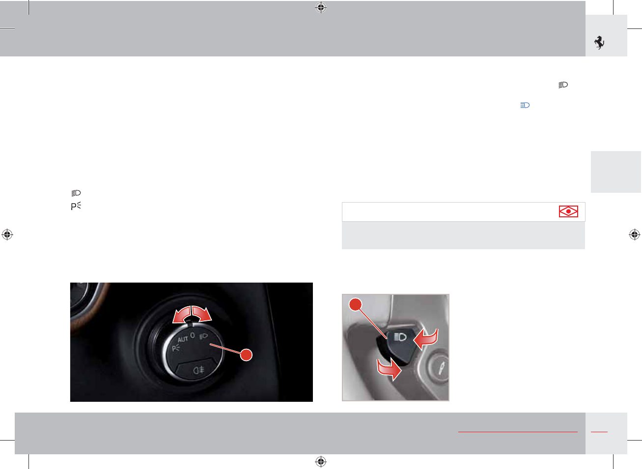
125
3
About your Vehicle
A
B
Lighting
The external lights and turn indicators only work when the ignition
key is in position II.
The external lights can be switched on and off manually or
automatically, depending on the ambient light.
Light switch
Switch A, on the dashboard to the left of the steering wheel, can be
set to four different positions:
0 Lights off
Low beams on (*)
Parking lights
AUT Automatic operation of the external lights according to
ambient light.
(*) The relative warning light on the instrument panel comes on.
High beams
To turn on the high beams when the light switch A is set to ,
push lever B on the steering wheel towards the dashboard. When
the high beams are on, the relative warning light on the
instrument panel comes on.
Then push lever B towards the dashboard or pull it back to turn off
the high beams and turn on the low beams.
Flashing the headlights
The headlights can be flashed by pulling back the left-hand lever B.
Flashing also occurs with lights off if the ignition key is set to II.
The high beams are used for flashing.
Important note
Follow the Road Regulations of the country you are travelling in
for using the high beams.
126 About your Vehicle
Important note
If the high beam control is activated, the high beams will
turn on every time the lights are activated automatically. We
recommend therefore that you turn them off every time the
twilight sensor deactivates the external lights.
Warning
If there is fog during the day, the running lights and low beams
will not be turned on automatically. The driver must always be
ready to turn on the lights manually and also the rear fog lights,
if necessary.
Important note
After automatic activation of the external lights, it will always
be possible to turn on the rear fog lights manually. When
the external lights are deactivated automatically, the rear fog
lights are also turned off (if active) automatically. Therefore,
if necessary, the driver will have to turn on the rear fog lights
manually upon the next automatic activation.
Warning
The driver is always responsible for turning on the external
lights, depending on the ambient light and in compliance with
the regulations in force in the country of use. The automatic
system for turning on and off the external lights must be
considered an aid for the driver. If necessary, turn the lights on
and off manually.
Parking lights
The parking lights work only with the ignition key in position 0 or
with the key removed.
They are activated by turning the light switch A to position .
When the parking lights are on, the warning light illuminates on the
instrument panel .
When the parking lights are on, press and hold one of the two turn
indicator buttons C on the steering wheel (see page 127) for more
than 0.5 seconds to turn on the single-side parking lights on the
corresponding side; press the same turn indicator again for more
than 0.5 seconds to go back to full parking lights.
When the partial parking lights are on (on only one side of the
vehicle), the running light warning light turns off whereas the
vehicle symbol indicating which parking light is on (left or right) is
displayed on the left TFT display for 10 seconds.
When the light switch A is turned to AUT and the ignition key is in
position II, the running lights, low beams and number plate lights
turn on and off automatically according to the ambient light.
Important note
The high beams can only be activated manually by pushing the
left-hand lever B towards the dashboard.
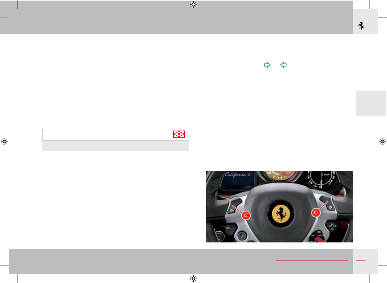
127
3
About your Vehicle
Twilight sensor
The twilight sensor is comprised of a global sensor which measures
the ambient light upwards.
Sensor sensitivity can be set to three levels: call up the MENU
screen page, select the items “Car setup” and “Light sensor” and
use the UP and DOWN buttons to select the desired level.
In the event of sensor failure, the system switches on the low beams
and running lights, regardless of the daylight conditions; a failure
message will appear on the instrument panel display.
The failure indication will be displayed as long as the light switch
is turned to AUT. If this occurs, we recommend that you deactivate
the automatic system and turn on the external lights manually if
necessary.
Important note
If this occurs, contact the Ferrari Service Network.
Day lights
The LEDs on the headlights serve as front turn indicators and day
lights. To activate or deactivate the day running lights, call up the
MENU screen page on the left TFT display, select the items “Car
setup”, “Day lights” and select ON to activate the function and OFF
to deactivate it.
Turn indicators
Quickly press the left indicator or right indicator button C on the
steering wheel to switch on the relevant turn indicator.
The relative warning light or on the instrument panel
comes on.
The turn indicator goes off when the steering wheel is realigned.
Holding down one of the two C buttons (for more than
0.3 seconds) temporarily switches on the relevant turn indicator: it
is switched off after 3 flashes (“lane change” function).
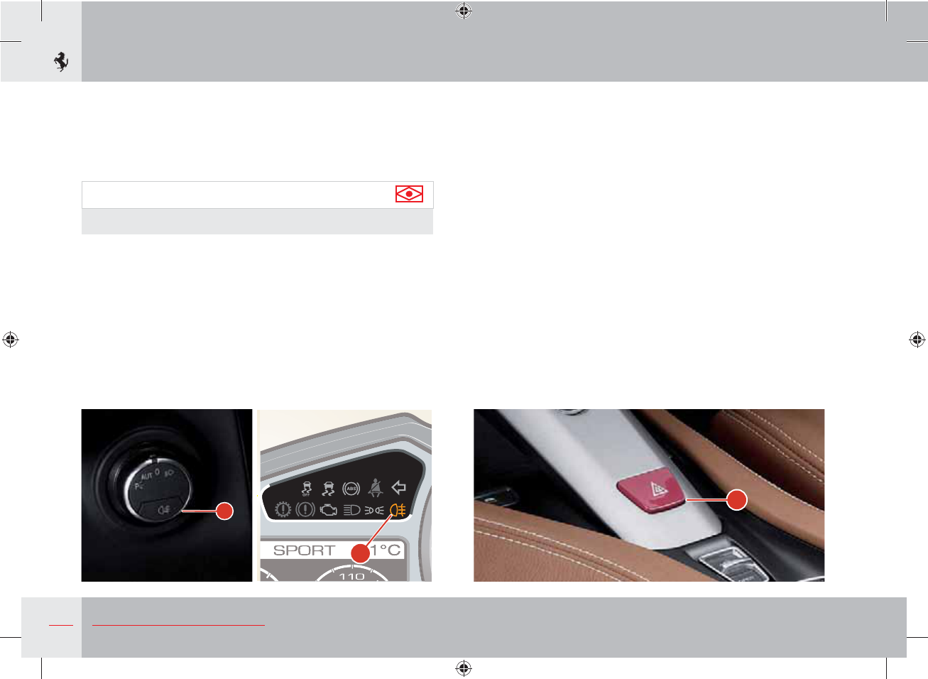
128 About your Vehicle
A
E
D
Hazard warning lights
Press button A to turn on the hazard warning lights. All the turn
indicators will start blinking intermittently. These lights will operate
with the ignition key in any position.
When the hazard warning lights are on, the relative warning lights
on the instrument panel and the button flash.
To turn them off, press the button again.
“Auto Hazard” function
The “Auto Hazard” function automatically switches on the hazard
warning lights in the event of sharp braking.
To activate or deactivate the function, call up the MENU screen
page, select the items “Car setup”, “Auto Hazard” and select either
“ON” or “OFF”.
“Follow me home” function
With the “Follow me home” function, the low beams stay lit for a
preset period of time once the engine has been turned off and light
up the area around the vehicle to help the driver and passengers
see their way in the dark.
Rear fog lights
The rear fog lights are turned on only if the high beams or low
beams are on when button D is pressed; the relevant warning
light E on the instrument panel comes on to indicate that they have
been turned on.
Important note
Use the rear fog lights only in poor visibility conditions.
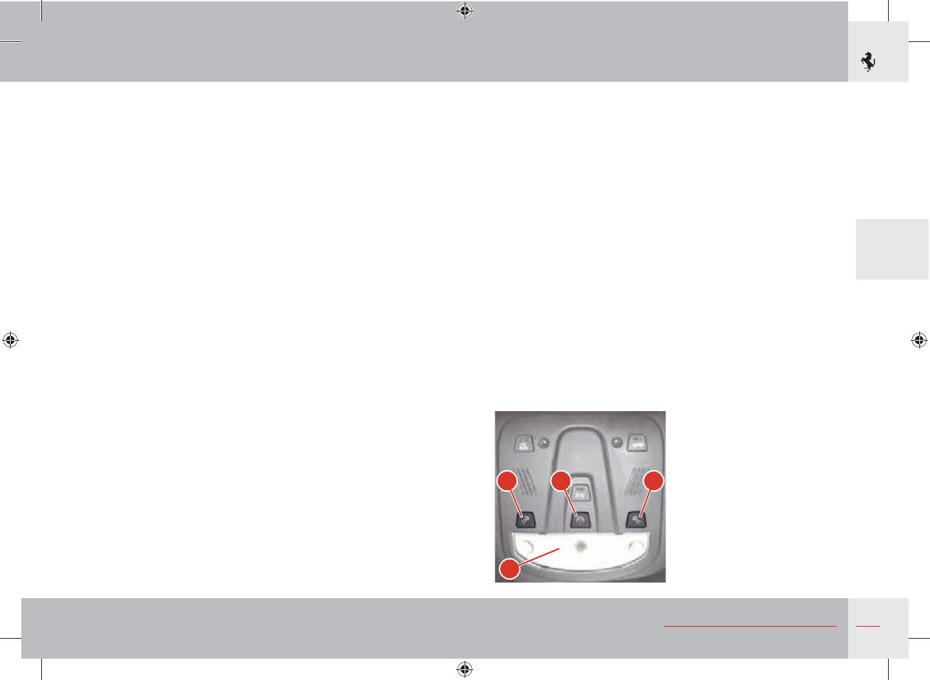
129
3
About your Vehicle
D
FEG
To activate this function manually, push the high beam/flash stalk B
(see page 125) with the ignition key turned to 0 or removed, within
3 minutes of switching off the engine. This timer is reduced to
30 seconds if the driver side door is opened. Each time lever B is
pressed, the period of time that the low beams remain on increases
by 30 seconds up to a maximum of 210 seconds.
Each time lever B is pressed, the message “Follow me” appears on
the left TFT display followed by the preset period of time that the
low beams remain on.
AFS2 adaptive headlights (optional)
The AFS2 adaptive headlight system (available on request) enables
synchronous movement of the left and right front beams (high
and low) and has been designed to illuminate the road better and
reduce areas of shadow in the vehicle's trajectory.
The headlights' swivel angle, which ranges from 8° inwards and
15° outwards, is defined by the steering angle.
The AFS2 system also uses a “Dynamic Levelling” device that
directs the light beam vertically when accelerating and braking by
moving the headlights up to 1.9° upwards when braking and up to
1° downwards when accelerating.
The adaptive headlight system deactivates its corrective action
when driving round bends at low speed.
Dome light
When the doors are closed, the dome light D on the roof can be
turned on or off using the switch E.
Switches F and G turn the driver-side and passenger-side spotlights
on and off.
The dome light activates automatically in the following conditions:
- when a door is opened, for approx. 3 minutes;
- when all the doors are closed and the key is in position 0, for
approx. 10 seconds;
- when the key is removed, for approx. 10 seconds;
- when the doors are unlocked, for approx. 10 seconds;
- when the inertia switch is activated, for approx. 15 minutes.
The dome light deactivates automatically in the following conditions:
- after the preset activation time expires;
- when the doors are closed and the key is in position II;
- when the doors are locked;
- when the inertia switch is reactivated.
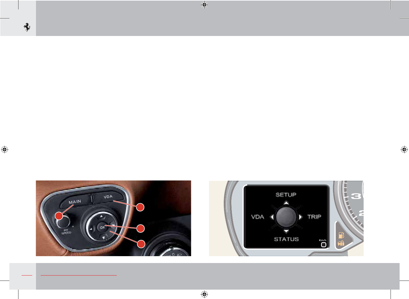
130 About your Vehicle
A
B
C
D
Left TFT display
Located on the instrument panel, it performs the following
functions:
- displays the control parameters;
- displays general information while driving;
- displays fault warnings.
The driver can interact with the system by selecting the
configuration and setting the parameters using the controls on the
dashboard to the left of the steering wheel.
The display is activated and set by pressing the MAIN (A), VDA
(B), OK (C) and UP, DOWN, LEFT, RIGHT (D) buttons.
MAIN screen page
If you press the MAIN button, you activate the MAIN screen page
which can be used to access the four screen page groups SETUP,
VDA, TRIP and STATUS. These groups contain the following screen
pages:
SETUP (pressing the UP button)
MENU screen page
STATUS (pressing the DOWN button)
SPORT screen page
SPORT 2 screen page
TYRES screen page (only if TPMS is present)
VDA (pressing the LEFT button)
Manettino status screen page
TRIP (pressing the RIGHT button)
TRIP A screen page
TRIP B screen page (only if previously enabled).
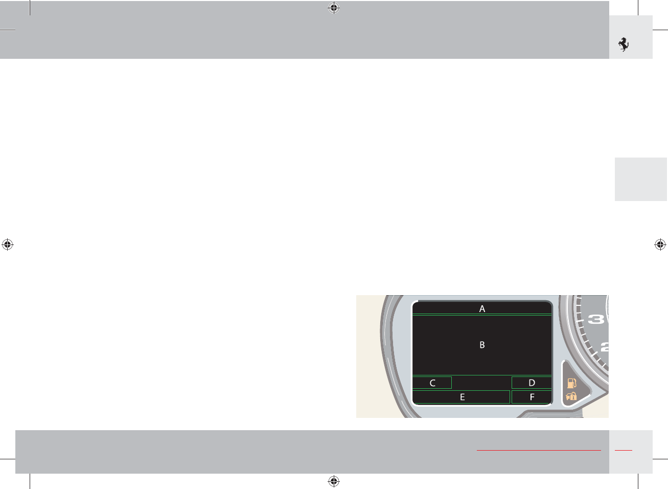
131
3
About your Vehicle
Press the RIGHT and LEFT buttons to sequentially switch between
screen pages in a group. Press RIGHT to go to the next screen page
(for example, in the STATUS group from SPORT to SPORT 2)
and press LEFT to go to the previous screen page. Press the RIGHT
button after the last screen page to go back to the first screen page
and press the LEFT button after the first screen page to go back to
the last screen page.
Six different screen areas are available, depending on the
information type chosen:
A - selected driving mode (Manettino setting), outside temperature
and “Warning: danger of ice” icon;
B - display of control gauges, parking sensor screen, display of
abnormal events/warnings (message text and special symbol,
when available), display of brightness adjustment function;
C - multimedia info;
D - call inform/address book;
E - fuel level gauge, fault icon and speed repetition;
F - total odometer.
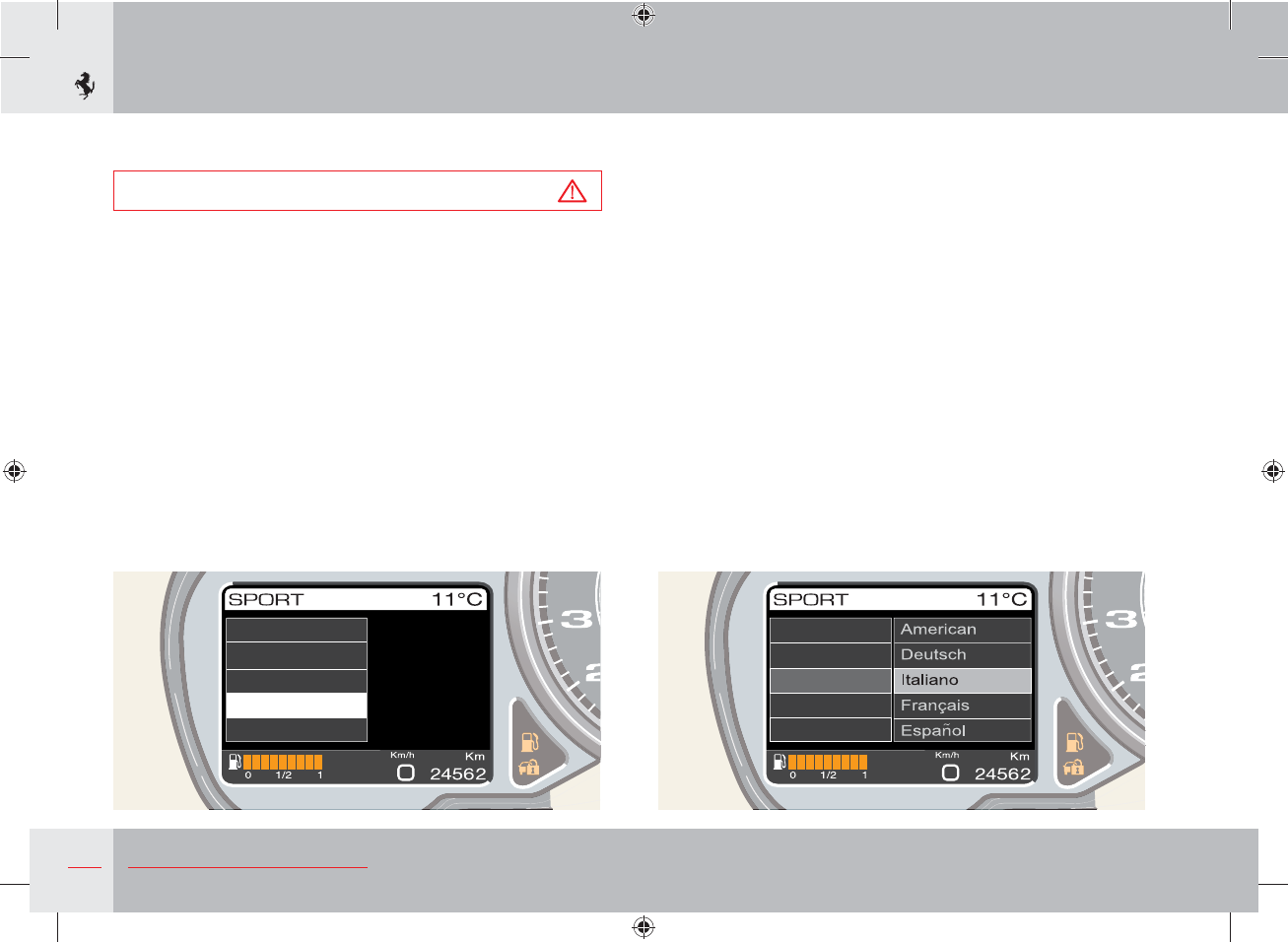
132 About your Vehicle
Display setting and configuration of vehicle parameters
Warning
The display settings and parameters must only be adjusted while
the vehicle is stationary
MENU screen page
Display setting and configuration of the various vehicle parameters
is possible using the MENU screen page (the only screen page in
the SETUP group) that can be directly called up by pressing the UP
button when the MAIN screen page is activated.
Navigation within the menu is on several levels; the first level offers
a list of items through which the following parameters can be set or
the following information can be displayed:
- Dimming: display dimming setting.
- Display setup: display setting.
- Date/Hour: date and time setting.
- Language/M.U.: language and units of measurement setting.
- Car setup: vehicle parameter configuration.
- Manometer setup: manometer display setup.
- Calibr. TPMS: calibrating the TPMS system.
- Service: information on scheduled maintenance.
These items are the main menu functions. To scroll through the list
of items, press the UP and DOWN buttons; to select the required
function, press and quickly release the OK button or the RIGHT
button.
Language
M.U. Distance
M.U. Temp.
M.U. Pressure
Dimming
Display setup
Date/Hour
Car setup
Language/M.U..Language/M.U.
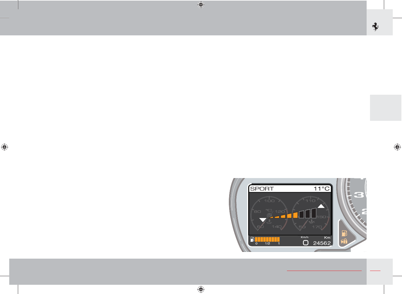
133
3
About your Vehicle
Once the function has been selected, the individual subfunctions or
parameters that can be activated are displayed. To select them, use
the UP and DOWN buttons and press and quickly release the OK
(or RIGHT) button to activate a subsection or activate the selected
parameter.
To go back to a previous level in the menu hold down the OK
button, press the LEFT button or select the BACK item which is
normally in the list of subfunctions. If no operation is performed
for at least 10 seconds, the previous menu level reappears on the
display.
Adjusting brightness
The brightness setting of the two TFT displays on the instrument
panel is adjusted from the specific option in the MENU screen.
DIMMING
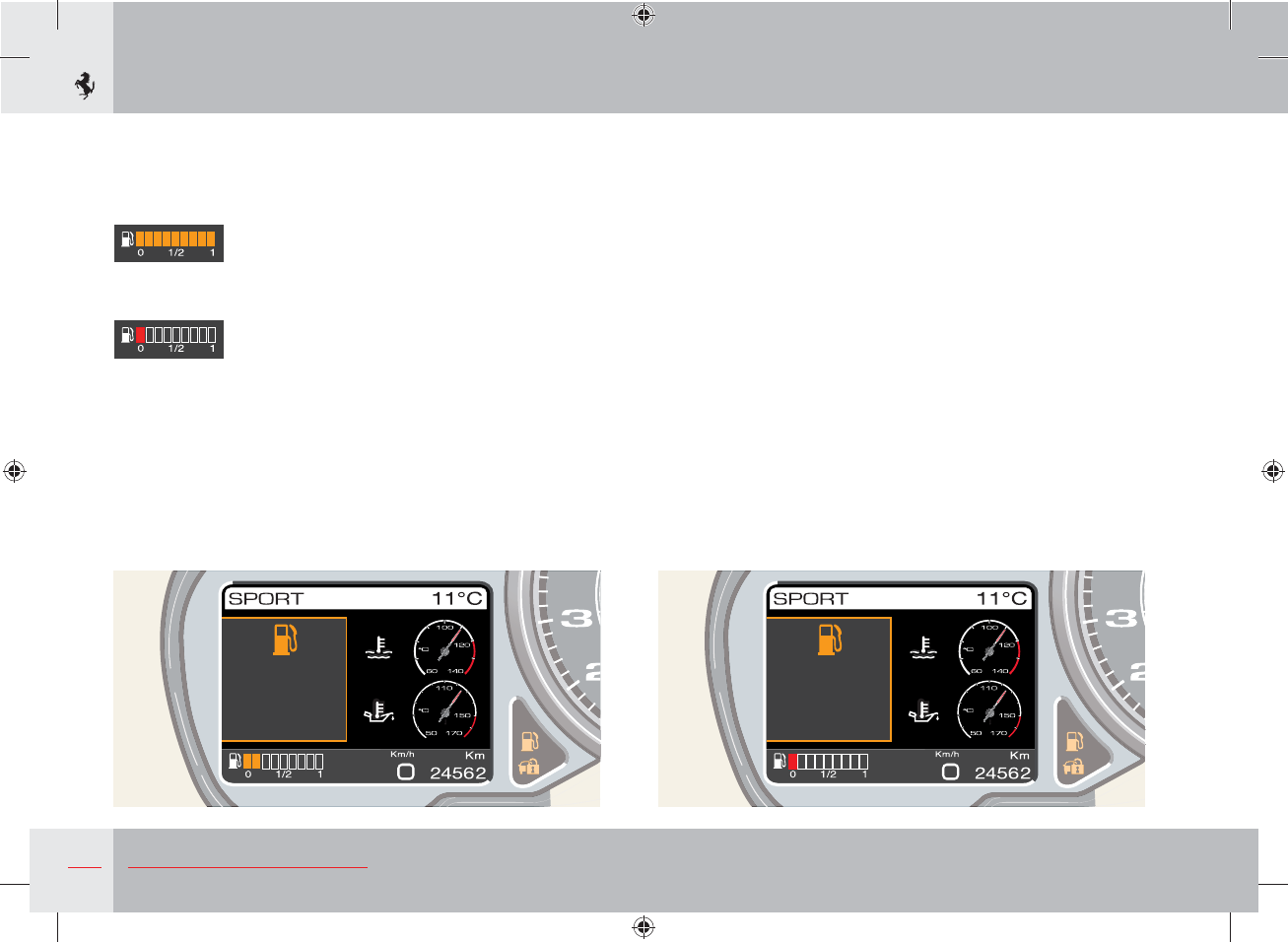
134 About your Vehicle
Fuel level gauge
The fuel level gauge is always displayed in area D of the display
(see page 131). The gauge has 9 yellow bars that gradually “turn
off” as the fuel level drops.
When the second bar goes off, the first bar turns red until fuel runs
out.
When the reserve fuel is reached, in addition to the activation of
the relative warning lamp on the instrument panel (see page 148),
the relative symbol and specific message, together with the
remaining range in Km, are shown on the display for 10 seconds. If
the condition that has generated it persists, this signal is repeated
every 8 km.
In limited cruising range conditions, the information on driving
range in km is replaced by the words “Limited cruising range”.
Fuel level
Low
Range
86 km
)XHOOHYHO
ORZ
/LPLWHG
FUXLVLQJ
UDQJH
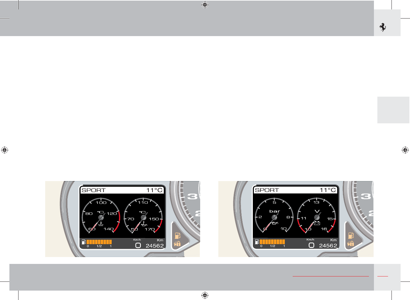
135
3
About your Vehicle
SPORT screen page
The SPORT screen page displays the following gauges:
- Engine coolant temperature.
- Engine oil temperature.
If the SPORT screen page is being displayed and an event occurs
that needs to be displayed as a symbol and/or special message, the
gauges are minimised.For further information, refer to the “Fault
visualisation logic” paragraph on page 146.
SPORT 2 screen page
The SPORT 2 screen page displays the following gauges:
- Engine oil pressure.
- Voltmeter.
If the SPORT 2 screen page is being displayed and an event occurs
that needs to be displayed as a symbol and/or special message, the
gauges are minimised.For further information, refer to the “Fault
visualisation logic” paragraph on page 146.
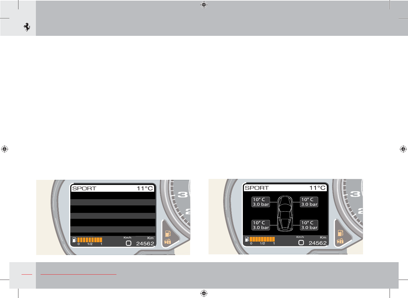
136 About your Vehicle
TRIP A
Maximum speed
Average speed
Travel distance
Travel time
Range
Mon 16 Nov
263
Km/h
124
Km/h
292.8
Km
03:36
h:m
204
Km
TRIP A and TRIP B screen pages
The TRIP A or TRIP B screen page displays the following
information:
- Maximum speed
- Average speed
- Travel distance
- Travel time
- Range
If the TRIP A or TRIP B screen page is being displayed and an
event occurs that needs to be displayed as a symbol and/or special
message, the screen page is minimised. For further information,
refer to the “Fault visualisation logic” paragraph on page 146.
TYRES screen page
The TYRES screen page displays a symbol of the vehicle with the
pressure and temperature values for each tyre.
If the TYRES screen page is being displayed and an event occurs
that needs to be displayed as a symbol and/or special message,
the screen page is minimised. For further information, refer to the
“Fault visualisation logic” paragraph on page 146.
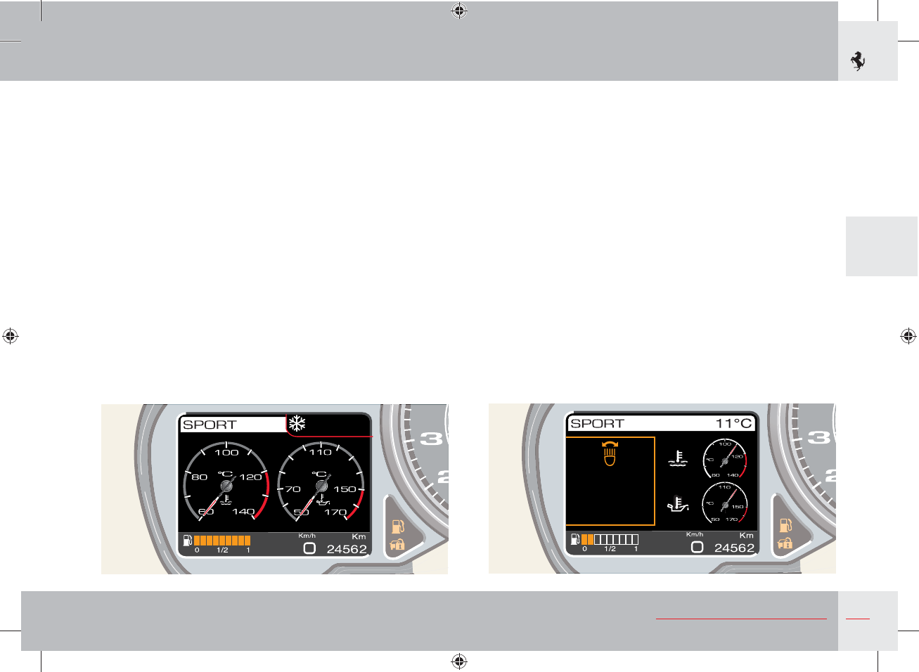
137
3
About your Vehicle
r
er ce
pt e ht
Ctr
ure
“Warning: danger of ice” display
To warn the driver of the presence of ice on the road if the outside
temperature is 3 °C (38 °F) or below, the “snow” symbol and the
“warning: danger of ice” message are displayed for 10 seconds in
the top right of the display.
When they are displayed, the symbol and message appear instead of
the outside temperature; after 10 seconds, the outside temperature
is displayed again and the “snow” symbol appears next to it as long
as the outside temperature remains 6 °C (43 °F) or below.
“Adaptive Light Control” function display
When a failure in the adaptive light system is detected on a bend,
the warning light flashes and at the same time, a message with a
special symbol is displayed.
The message is displayed for a set period of time. When this period
expires, the screen page disappears but the warning light continues
to flash until the situation is corrected.
The next time the engine is started, if the failure persists, the
warning light will flash and the same screen page described above
will be displayed.
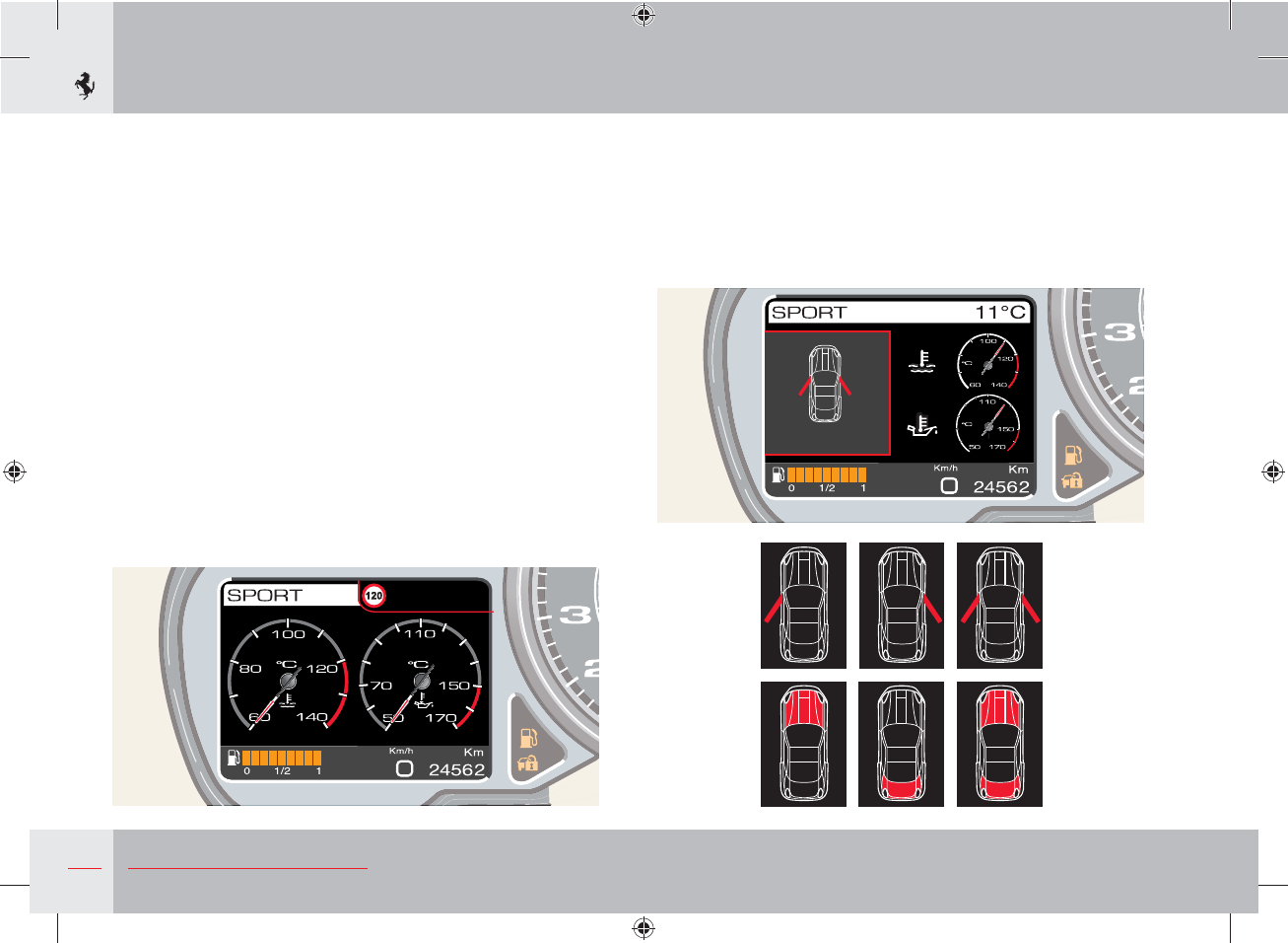
138 About your Vehicle
pee t
e cee e
rs pe
“Doors/Engine or luggage compartment lid open” function display
When the doors and the engine compartment or luggage
compartment lid are open, this is signalled by a screen page
in which the doors/lids which are open at the same time are
highlighted.
“Speed limit” function display
The MENU screen page can be used to set a speed limit in the
range 30 - 250 km/h with 5 km/h steps which sends a message
to the driver when exceeded. To set the speed limit, call up the
MENU screen page and select the options “Vehicle Config.” and
“Speed Limit”.
To set the value, use the UP and DOWN buttons. When the
minimum limit of 30 km/h is reached, press the DOWN button
again to deactivate the function or press the UP button after
reaching the maximum speed of 250 km/h. The function is
normally deactivated (OFF).
When the set limit is exceeded, the driver is informed in the
following way:
The symbol showing the set limit and a “Speed limit exceeded”
message appear in the top right of the display for 10 seconds
accompanied by an acoustic signal. Once the warning cycle has
ended, the message disappears whereas the symbol continues to be
displayed next to the outside temperature until the speed decreases
to 5 km/h below the set limit.
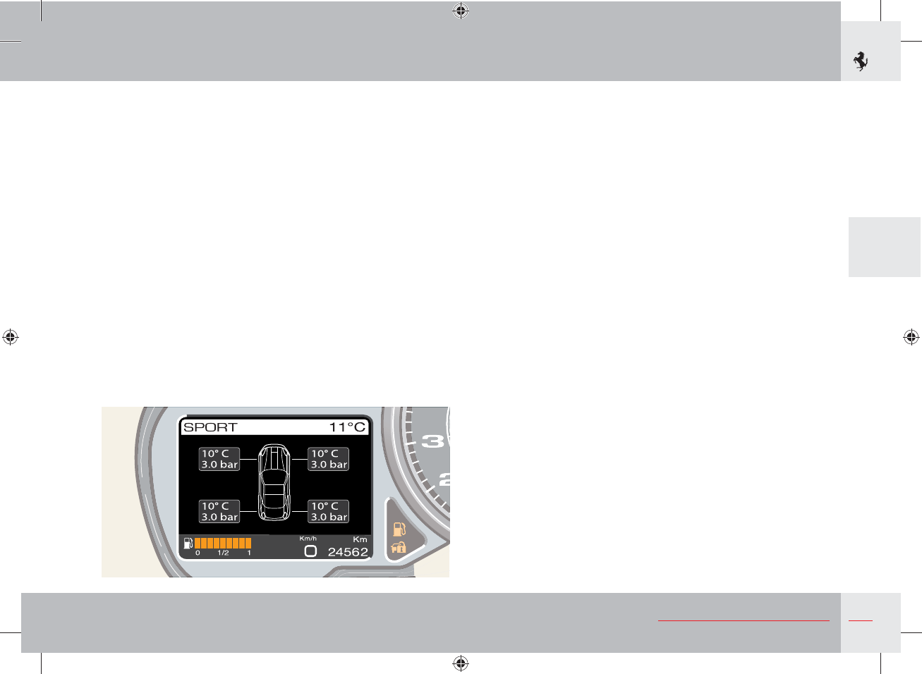
139
3
About your Vehicle
“Tyre pressure and temperature” display
The screen page showing the pressure and temperature values of
each tyre can be accessed using the “Display” button.
When the on-board instrument panel receives the signal from the
tyre pressure ECU that the pressure level of one or more tyres
is below the alarm threshold, a different screen page will appear
according to whether the value is low on one or more tyres.
Refer to the “Tyre pressure and temperature monitoring system”
section on page 71.
“Tyre puncture” display
When the pressure level of one or more tyres is below the alarm
threshold, regardless of the current display configuration, the
warning light comes on permanently and a message and special
symbol are displayed for vehicles fitted with normal tyres and one
for those fitted with Run Flat tyres.
Refer to the “Tyre pressure and temperature monitoring system”
section on page 71.
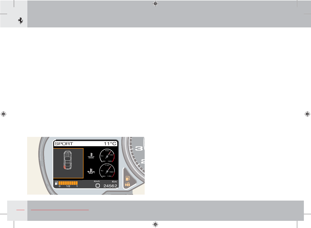
140 About your Vehicle
p ure
External lights failure display
The following failures can be displayed:
1 Stop lights failure
2 Number plate lights failure
3 Rear fog lights failure
4 Running lights failure (front and/or rear)
5 Turn indicators failure (front and/or rear).
If one of these failures occurs, a specific message that highlights the
faulty light is displayed.
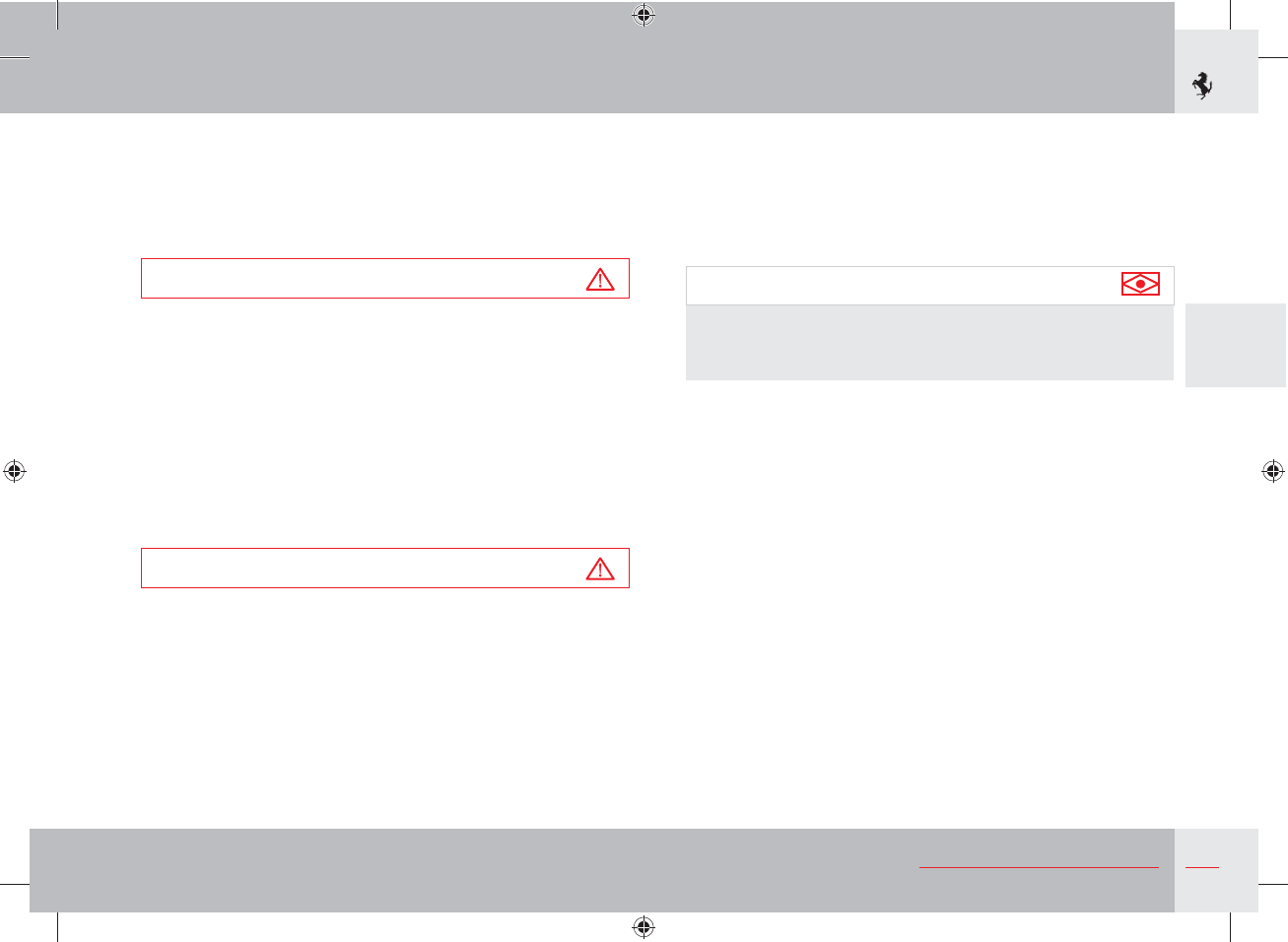
141
3
About your Vehicle
The rear parking sensors are automatically activated when the key
is in position II and reverse gear is engaged. When the rear sensors
are activated, an acoustic signal warns the driver that the system has
been activated. If the vehicle is also equipped with front sensors,
these can be activated or deactivated by pressing the relative button
on the roof panel (see page 158).
Important note
If the distance between the vehicle and the obstacle (see
page 123) is less than 400 mm, the parking sensors will not
allow the retractable hard top to be opened or closed.
“Stop and Go” function
The “Stop & Go” function, available on vehicles with front and
rear parking sensors, automatically activates the front sensors when
vehicle speed is 10 km/h or below. This system has been designed
to assist the driver in certain traffic conditions (e.g. tailbacks) and
signals when the minimum distance is reached between the vehicle
and the vehicle in front.
To activate or deactivate the system, call up the MENU screen page,
select the items “Car setup”, “Parking sensor”, and select one of the
two options, “STOP&GO ON” and “STOP&GO OFF”.
Indication of obstacles
The parking sensor system emits acoustic signals as soon as an
obstacle is detected which become more frequent as the obstacle
approaches. The acoustic signal stops immediately if the distance
from the obstacle increases whereas the tone cycle remains
constant if the measured distance from the central sensors remains
unchanged.
Parking sensors
To help the driver when parking, the vehicle is fitted with four
sensors in the rear bumper (rear parking sensors). The vehicle
can be fitted on request with four sensors in the front and rear
bumpers (front and rear parking sensors).
Warning
The system will only operate correctly if the sensors on the
bumpers are free of mud, dirt, snow or ice.
When approaching obstacles in front of or behind the vehicle,
the parking sensors inform the driver of the distance between the
vehicle and the obstacle by way of acoustic signals, which become
more frequent as the obstacle approaches, and visual signals in
area B of the TFT display (see page 131). By supplementing the
driver's direct visual information with that provided by the system
acoustic signals and visual warnings, potential collisions can be
avoided when parking.
Warning
It is the driver, however, who holds full responsibility for
parking manoeuvres and other potentially dangerous situations.
The system has only been designed as an aid during parking
manoeuvres, since it detects obstacles that are outside the
driver's range of visibility.
Use of the sensors therefore does not mean that the driver can
be less careful and attentive and not watch out for persons and
obstacles during parking manoeuvres.