Harman Consumer MS80100EV RF Remote User Manual TN5MS80100EV
Harman Consumer, Inc. RF Remote TN5MS80100EV
TN5MS80100EV_user manual
www.jbl.com
Hi-Level inputs from OEM head unit
or amp
Plug straight end
into MS-8. Plug angled end
into display.
Display
Note: Document your output connections in the table
located on page 2 for ease of reference during setup!
RCA outputs to
amplifier(s)
Remote Out connection provides +12V
output when the MS-8 is on. The MS-8
must turn on all system amplifiers.
RCA inputs from aftermarket
source unit
Circuit Protection:
25A ATC/ATO Automotive-type fuse.
Mic: binaural microphone
connection.
Note: Connect only the front right and left
full-range outputs from an aftermarket head unit
to inputs 1 and 2. Do not use inputs 3–8. Do not
connect the subwoofer output of an aftermarket
head unit to the input of the MS-8.
Remote In connection: Connect it to the remote
turn-on output of the audio-source unit (if the
source unit has a remote turn-on output) or the
vehicle’s accessory (ACC) power circuit.
Chassis
ground
input
Connect this first!
Speaker outputs to speakers MS-8 Remote
Volume
Down
Navigation
buttons Navigation
buttons
Select
Back
&
Menu
Mute
Volume
Up
Aux Input
Connect the headphone
output or line output of an
additional audio source to
the Aux Input.
USB Port
Remove sticker and connect USB
connector to a PC for firmware
updates only.
+12V
Connect it to the vehicle battery
through a fuse within 18" (45.7cm)
of the battery post.
MS8
Quick Start Guide
jbl®
13
12345
6
7
8
9
11
10
12
13
5
6
112134
9 7
810 12
3
0200CSK - JBL MS-8 Quick Start Guide Inlay.indb 3 08/03/10 15:22:38
www.jbl.com
QUICK START GUIDE
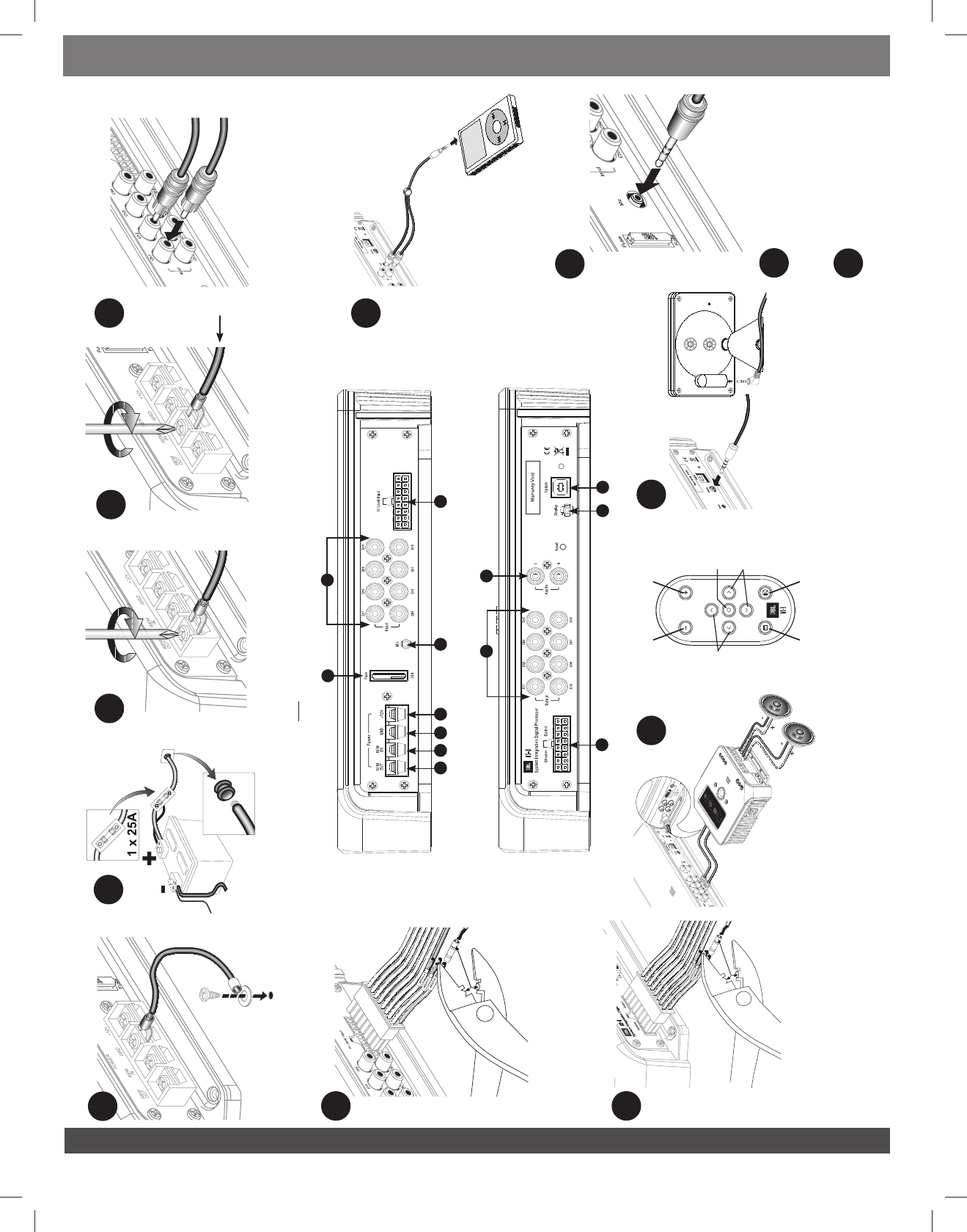
MS8 CONNECTIONS
1
Chassis ground input: Connect it to a paint-free spot on the vehicle chassis.
2
+12V: Connect it to the vehicle battery with a 25A fuse within 18 inches (45.7cm) of the
positive battery terminal. Use 12 AWG wire minimum!
3
Remote turn-on output: Connect it to the remote turn-on input of all amplifiers in the
system. The MS-8 MUST control the turn-on signal of the other devices that come after it
in the signal path. The output is +12 volts DC, 1A.
4
Remote turn-on input: Connect it to the remote turn-on output of the source unit if the
source has such an output. If not, this terminal can connect to the vehicle’s accessory (ACC)
power circuit. In either case, a connection with over +4 volts DC will trigger the unit,
accommodating a range of factory source units or amplifiers.
Input signal connections: Many factory-installed systems include on-board
equalization (EQ) and crossovers that make simple connection of aftermarket products
difficult. The MS-8 includes signal-summing circuitry, signal-conditioning EQ and time-
correction processing necessary to reconstruct a two-channel, flat, full-range signal
when you use the MS-8 with factory-installed equipment. Aftermarket head units with
RCA-type outputs provide a flat, full-range, two-channel signal on their front RCA-type
outputs. Connect only those outputs to the MS-8.
5
RCA-type audio inputs: If you use the MS-8 with an aftermarket head unit that includes
RCA-type outputs, connect the front outputs to the MS-8’s RCA-type inputs 1 and 2 only.
Do not connect any other output signals to RCA inputs 3–8.
6
Hi-Level inputs: If you use the MS-8 with a factory-installed head unit, or any head unit
that does not include RCA-type outputs, connect the front left and front right
speaker-level outputs from the head unit to “Hi Level Input” 1 and 2 on the MS-8. If the
factory-installed system includes a separate amplifier, connect the output of the amplifier
to the “Hi Level Input” of the MS-8. Note: Many factory-installed separate amplifiers
include separate channels for front tweeters and midranges and subwoofers. Connect ALL
of the front and subwoofer outputs to the speaker-level inputs of the MS-8.
Note: The subwoofer outputs of the factory amplifier MUST be connected only to the MS-
8’s input channels 7 and/or 8.
7
Aux input: Connect it to any auxiliary source with RCA audio outputs. Switching between
the standard inputs and the Aux input is done in the MS-8 menu.
8
Speaker outputs: Connect them directly to the speakers if the MS-8’s on-board
amplifiers will be used. Fill out the chart below to simplify channel assignment during
setup.
9
Preamp outputs: If the MS-8’s onboard amplifiers won’t be used, connect the RCA-type
inputs of additional amplifiers to the MS-8’s RCA-type output connectors. Some speakers
may be powered by the MS-8’s amplifiers and some by additional amplifiers, but only use
one connection type per output. For example, Output Channel 1 may use the MS-8’s
amplifier OR an additional amplifier, but not both. Do not connect a speaker to Speaker
Output 1 AND an amplifier to RCA-type Output 1. Fill out the chart below to simplify
channel assignment during setup.
10
MS-8 Display: Connect it to the MS-8 using the supplied cable. You MUST connect the
display during setup, but you may disconnect it after setup. If you do not install the
display, you cannot adjust the MS-8, and the MS-8’s remote control will not function.
11
Microphone input: You must connect it to the MS-8 during setup. Once setup is
complete, unplug the microphone and store it in a safe place. Do not use any other
microphone with the MS-8.
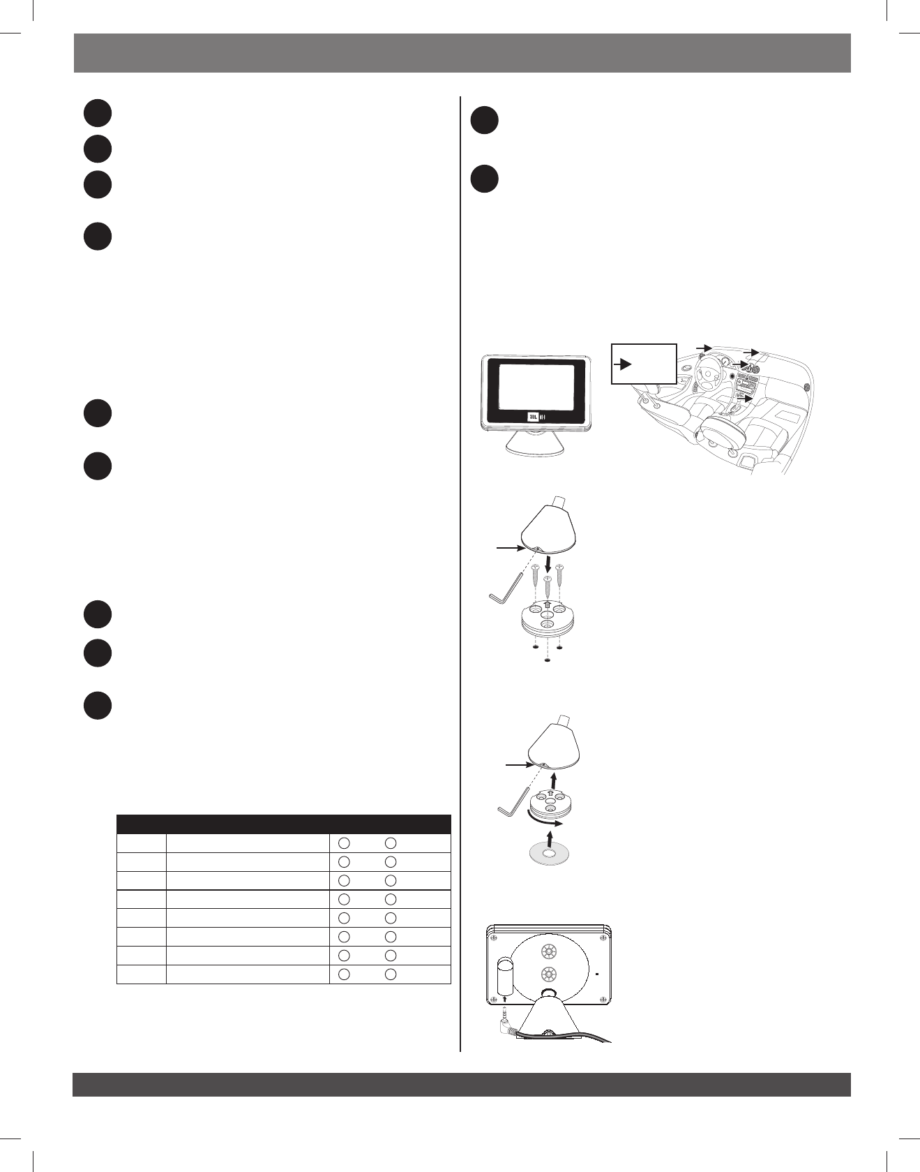
DISPLAY INSTALLATION
Choose a location for the display that is within easy sight while you are operating the vehicle but
that does not obstruct your view or normal vehicle operations. Windshield mounting or mounting
on the top of the dashboard between the driver and the windshield may be against the law in
your municipality. Be sure to consult local laws before mounting the display.
Possible
Mounting
Locations
Attach the Base
Use the three (3) supplied screws to secure the base plate,
and then twist the display base into position. Tighten the set
screw to secure the base to the mounting plate.
Mounting with screws
Set
screw
If you use the supplied adhesive pad, be sure to clean the
base and the mounting surface with the supplied alcohol
pad to ensure proper adhesion. Once you have secured the
base to the mounting surface, twist the display base into
position. Tighten the set screw to secure the base to the
mounting plate.
Mounting with adhesive
Set
screw
Plug in the Cable
Plug the angled end of the display cable into the
MS-8 display. Ensure that the other end of the
display cable is connected to the MS-8.
Output # Channel / Speaker Connected Output Connector Used
1RCA SPEAKER
2RCA SPEAKER
3RCA SPEAKER
4RCA SPEAKER
5RCA SPEAKER
6RCA SPEAKER
7RCA SPEAKER
8RCA SPEAKER
4
0200CSK - JBL MS-8 Quick Start Guide Inlay.indb 4 08/03/10 15:22:40
www.jbl.com
ENGLISH
QUICK START GUIDE
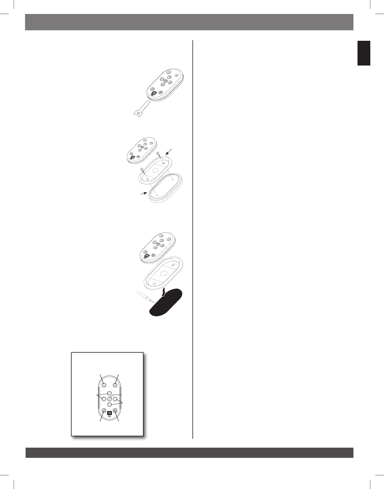
REMOTE CONTROL
The MS-8 features an RF (radio-frequency) remote to control all of the MS-8’s user-selectable
features. There are dedicated volume buttons on the remote’s top that always control the
system volume, regardless of which menu screen is active.
Before you use the remote, pull off and discard its battery-
saver tab. Since the remote operates by radio frequency, you
do not need to point the remote toward the display.
While you can leave the remote unmounted or secure it with
Velcro®, JBL offers two safe and convenient methods to secure
the remote: surface mounting and flush mounting.
Surface Mount
Find a suitable location with flat surface where the RF 1)
receiver is located.
Ensure that no wiring or hazards are below the 2)
surface.
Remove remote from mounting cup. Observe position 3)
of finger cutout for final positioning.
Attach cup with trim ring to flat surface with two (2) 4)
supplied screws or double-sided tape.
Flush Mount
Find a suitable location with flat surface and 1/2" 1) (12.7mm)
of clearance below.
Ensure that no wiring or hazards are below the surface.2)
Detach the trim ring from the mounting cup. Place on 3)
mounting surface.
Mark cutout opening using the inside of the trim ring 4)
as a template.
Cut the mounting surface to allow the mounting cup 5)
to sit flush in the cutout.
Remove remote from mounting cup. Observe position of 6)
finger cutout for final positioning.
Press the remote into place and secure it to the ounting surface with glue, double-sided 7)
tape or other materials. Some customization may be required.
MS-8 RF
remote
Battery-
saver tab
Finger
cutout
Surface
mounting
trim ring
MS-8 Remote
Volume
Down
Navigation
buttons Navigation
buttons
Select
Back
&
Menu
Mute
Volume
Up
Flush
mounting
cup
SETTING UP THE MS8
The setup procedure consists of four main parts: Language Selection, Input Setup, Output Setup
and Acoustic Calibration. During Input Setup, the MS-8 uses a setup CD to analyze and condition
the input signal for further processing. During Output Setup, you will configure the basic crossover
settings and identify the output channels. During Acoustic Calibration, the MS-8 will automatically
equalize the signal that it sends to the loudspeakers and optimize their response for up to four
seating positions, using the included binaural microphone. You must complete all of these steps
in sequence. If you stop the setup procedure before completing all of the steps, the MS-8 will
start at the beginning of the last complete section when you turn it back on. Be sure to have the
output-configuration chart you filled out during installation handy. It will make configuring the
outputs easy.
1. Turn on the MS-8
Start the MS-8 by turning on the head unit (or turning the car’s key to the ACC position if you’ve
connected the REM In terminal to ACC power).
2. Choose Your Language
The MS-8 boots immediately to the language-selection screen the first time it’s powered up.
Once this screen appears, choose your language. Language > English.
3. Input Setup
Once you have chosen the language, the MS-8 will display the Input Setup Menu.
Important: You •must use the calibration CD provided with the MS-8 for this step. Do not
convert the CD to a compressed file format (MP3, WMA, AAC, M4A or any other). If you “rip”
the CD, do so only as a copy (WAV file), not a compressed format, and ensure that your media
player can play a WAV file format.
If you are using an aftermarket head unit and have connected the head unit’s RCA-type outputs
to the MS-8’s inputs 1 and 2, select Skip Input Setup and go directly to the Xover
Setup section and menu. If you are using a factory-installed head unit connected to the MS-8’s
speaker-level inputs, select Input Setup and follow the Input Setup procedure that
follows.
Set the head unit’s bass, treble, balance and fader controls to their “flat” or center position. a.
If possible, defeat the factory system’s additional processing (Dolby® Pro Logic II, Logic 7,
seating-position selector, user-selectable equalization, etc.). Consult your vehicle’s owner’s
manual for instructions.
While the b. Input Setup screen is displayed, follow the on-screen instructions. Insert the
supplied MS-8 CD into the audio source unit, and press “PLAY” on the source unit.
While the CD is playing, the MS-8 will analyze the input signal to ensure that it is receiving the
correct signals and that both right and left signals are present. The MS-8’s display will show
Signal, Level and Balance, and there must be an OK displayed next to each one
before you can continue.
If •None appears next to Signal, be sure that the head unit is outputting signal (increase
the volume control), and/or check the MS-8’s input connections.
If •Noisy appears next to Signal, ensure that the head unit’s volume control isn’t all he
way up, and turn off the car’s engine (if the car is running), but be sure not to turn the key
past the accessory (ACC) position.
If the display reads •High or Low next to Level, adjust the head unit’s volume control
until OK appears.
If •Left or Right appears next to Balance, adjust the head unit’s balance control until
OK appears.
Select c. Continue when the CD is playing Input Setup > (Press PLAY on CD) >
Continue
The display will read Acquiring.... while the MS-8 analyzes and corrects the signal. Once the
procedure is complete (up to a minute or two), follow the instructions on the screen: turn the
head unit’s volume down, remove the CD and select Continue.
5
0200CSK - JBL MS-8 Quick Start Guide Inlay.indb 5 08/03/10 15:22:40
www.jbl.com
QUICK START GUIDE
4. Output Setup
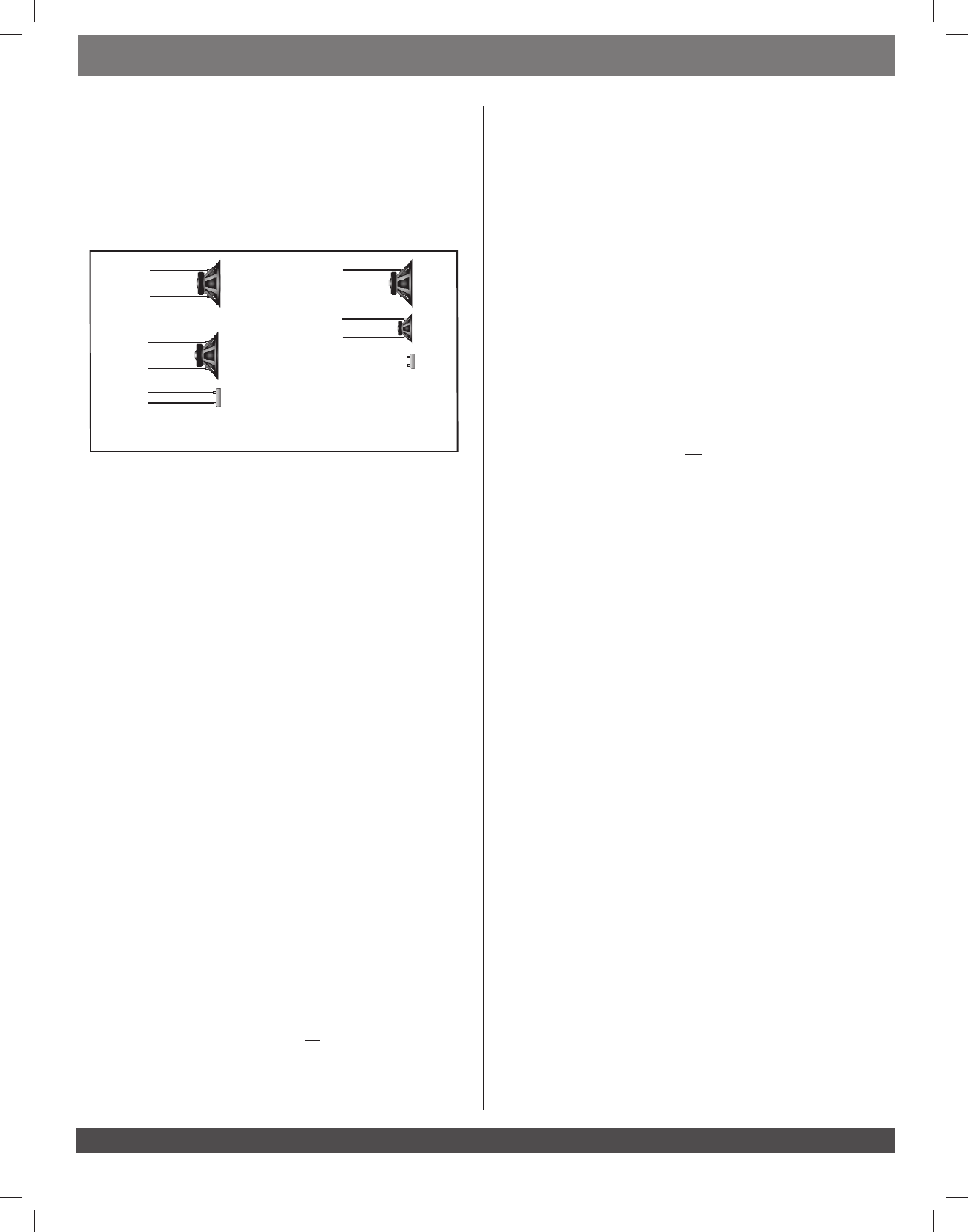
Xover Setup
During Xover Setup and Channel Selection, you will help the MS-8 configure the system. You
must enter information according to a specific sequence. If you make a mistake and need to
reenter information, you’ll have to reenter all the information that follows as well. Refer to the
configuration chart you filled out during Installation to make this process easy.
During Xover Setup, None, 1 or 2 and 1 way, 2 way or 3 way refer to the number of MS-8
output channels that will be devoted to driving a particular set of speakers.
1 way
2 way 3 way
Full Range
Mid
Tweeter
Mid
Tweeter
Woofer
Select Sub (Subwoofer)
Select1) (None), (1) or (2), depending on the number of output channels that will be
devoted to driving a subwoofer or system of subwoofers.
Selecting 2) (None) moves the menu screen to Front. If you’ve selected (1) or (2), select a
Subsonic Filter frequency (20Hz–50Hz). We recommend 20Hz.
Select 3) Subsonic Slope (6dB–4dB/octave). We recommend 12dB/octave.
Select 4) Sub/Front Xover frequency between the Subwoofer and Front speakers
(50Hz–200Hz). We recommend 80Hz.
Select 5) Sub/Front Slope between the subwoofer and front speakers (6dB–24dB/
octave). We recommend 24dB/octave.
Select Front (Front Speakers)
Select (1) 1 way), (2 way) or (3 way), according to the diagram above in Xover Setup.
If there is no subwoofer, select 2) Front Hi Pass frequency (20Hz–100Hz).
Select 3) Front Hi Pass Slope (6dB–24dB/octave).
If you are using a two-way front4a) , select the Front Lo/Hi Xover frequency
(50Hz–10kHz) and Front Lo/Hi Slope (6dB–24dB/octave) between the midrange
and tweeter.
If you are using a three-way front4b) , first select the Front Lo/Hi Xover frequency
(100Hz–10kHz) and Front Lo/Mid Slope (6dB–24dB/octave) between the woofer
and midrange. Next, select the Front Mid/Hi Xover frequency (20Hz–10kHz) and
Front Mid/Hi Slope (6dB–24dB/octave) between the midrange and tweeter.
Select Center (Center Speaker)
Select 1) (None), (1 way) or (2 way), according to the diagram above. If you selected
(None), skip to the next set of speakers: Side.
If you selected 2) (1 way) or (2 way), select Center Hi Pass frequency (50Hz–10kHz).
We recommend 80Hz.
Select 3) Center Hi Pass Slope (6–24dB/octave). We recommend 24dB/octave.
If you are using a two-way center, next select the4) Center Lo/Hi Xover frequency
(50Hz–10kHz) and Center Lo/Hi Slope (6dB–24dB/octave) between the and tweeter.
Select Side (Side or Rear Speakers)
Note: If you have side AND rear speakers, input the information for the side speakers here and
the rear speakers in the next step (Rear). If you have ONLY side OR rear speakers, input the
information for those speakers in this step (Side) and skip Rear.
Choose 1) (None) or (1 way). (Separate channels for tweeters are not available for side or
rear speakers).
Choose 2) Side Hi Pass frequency (50Hz–10kHz). We recommend 100Hz.
Choose 3) Side Hi Pass Slope (6dB–24dB/octave). We recommend 24dB/octave.
Select Rear(Rear Speakers)
If you have entered information for side speakers, and you’ll be using rear speakers as well, enter
the information for the rear speakers. If you are using only one set of speakers in the back of the
car or there are no speakers in the back of the car, select (None).
Choose 1) (None) or (1 way).
Choose 2) Rear Hi Pass frequency (50Hz–10kHz). We recommend 100Hz.
Choose 3) Rear Hi Pass Slope (6dB–24dB/octave). We recommend 24dB/octave.
If you need to make corrections, select the appropriate speaker location from the menu and
reenter the information. Then reenter all of the information that follows as well.
When you are finished with all filter settings, select Done.
Channel Selection
This menu assigns the outputs configured in the MS-8’s Xover Setup to specific output channels
by number. The menu will display only valid choices (according to the entries in Xover Setup).
Select the output channel based on the connections you documented in the output-channel
configuration chart on page 2.
If a speaker or amplifier is connected to Channel 1, select 1) Channel 1 from the Channel
Selection menu.
Select the appropriate speaker configuration type for 2) Channel 1. Depending on the
entries in Xover Setup, the following choices may be available:
(FL) = Front Left (FR) = Front Right
(FL Hi) = Front Left High (FR Hi) = Front Right High
(FL Mid) = Front Left Midrange (FR Mid) = Front Right Midrange
(FL Lo) = Front Left Low (FR Lo) = Front Right Low
(Sub1) = Subwoofer 1 (Sub2) = Subwoofer 2
(Ctr) = Center (Ctr Hi) = Center High
(Ctr Lo) = Center Low
(SL) = Side Left (SR) = Side Right
(RL) = Rear Left (RR) = Rear Right
If a speaker or amplifier is connected to Channel 2, select 3) Channel 2 and then select the
appropriate configuration from the list that appears in the display.
Repeat the procedure for the other channels to which a speaker or amplifier is connected. 4)
If you make a mistake, select the channel that you want to correct, and then enter the
correct selection. The MS-8 counts the number of channels used and will not allow duplicate
entries. Check your entries carefully against the configuration chart. Once you’re satisfied
that all is correct, select Done in the Channel Selection menu.
Output Diagnostics
This screen is provided to help you check your work before you proceed to Acoustic Calibration.
Select any of the displayed speaker locations to hear test noise through all of the channels
dedicated to that location. For example, if you’ve set up a three-way front system, selecting
Front Right will send test noise to the three channels you’ve designated as Front Right
(FR Hi, FR Mid and FR Lo). Listen carefully as you move through the speaker locations.
If you’ve made a mistake, correct your configuration chart and press the Menu button to return
to the beginning of the Channel Selection menu. Then enter the all of the correct
information starting at the beginning. You may also correct the mistake by reconnecting the
RCA or speaker-wire connectors to the MS-8.
Once you’ve determined that all connections and selections are correct, select Done in the
Output Diagnostics menu. Speaker Configuration Complete will appear. Next,
select Continue.
Acoustic Calibration
In order to complete MS-8 setup, you must make acoustic measurements for the driver’s seating
position. You may also make acoustic measurements for up to three additional seats. For the
best results for you and a single passenger, be sure to make measurements in the driver’s and
passenger’s seats.
Connect the included binaural microphone to the input jack on the MS-8 labeled “Mic.” Carefully
route the microphone’s cable to the driver’s seat, leaving enough excess wire to accommodate
the movements of your head. Sit in the driver’s seat and place the mic headset on your head. Be
sure that the left and right microphones are on the correct ears!
MS-8 Crossover Configurations
6
0200CSK - JBL MS-8 Quick Start Guide Inlay.indb 6 08/03/10 15:22:41

www.jbl.com
ENGLISH
QUICK START GUIDE
If the MS-8’s internal amplifier is set to drive the front speakers, set its volume to –20dB. If an
external, higher-powered amplifier will drive the front speakers, set the volume to a level lower
than –20dB.
In either case, the test-noise sweeps that you will hear during acoustic calibration should be
about as loud as someone sitting in the passenger’s seat speaking at a normal conversational
level. Performing acoustic calibration with a level that’s too high will negatively affect the
calibration results.
Press “Select” to select Acoustic Measurement 1 of 4.
Setup in the Driver’s Seat
Sit in the driver’s seat and position the binaural microphones over your ears.1)
Look straight forward.2)
Select 3) Go.
Hold your head still until the test signals stop and the next screen (4) Acoustic
Measurement 2 of 4) appears on the display.
Continue looking forward for the second measurement.5)
Select 6) Go.
Hold this position until the test signals stop. Note: This test signal takes a little longer, so 7)
be sure to hold your head still until it has completed and the next screen (Acoustic
Measurement 3 of 4) appears.
Turn your head toward the driver’s side mirror for the third measurement.8)
Select 9) Go.
Hold this position until the test signals stop and the next screen 10) (Acoustic
Measurement 4 of 4) appears.
Turn your head toward the passenger’s side mirror for the final measurement.11)
Select 12) Go.
Hold this position until the test signals stop and the next screen (13) Driver's Seat /
Next seating position / Done / Remeasure seating position /
Quit) appears.
Setup in the Passenger’s Seat
To measure the front passenger’s seat, select Next seating position. Note: After the
front passenger’s seat is completely measured, Next seating position will refer you to
the driver’s rear seat and, finally, to the passenger’s rear seat.
If you do not wish to measure additional seating positions, select Done.
If you think you’ve made a mistake, if there were any loud external noises at the time of the
measurements, or if you want to remeasure the seating position for any other reason, select
Remeasure seating position.
If the level of the test-noise sweeps was louder than normal conversational level, select Quit to
abort Acoustic Calibration and to return to the beginning of Acoustic Calibration to re-adjust the
level.
Repeat these steps for up to four seating positions. When you have completed all measurements,
select Done.
Acoustic Measurement Complete.......Please Wait will appear while the MS-8
calibrates the system. When the calibration is complete, the Main Menu will appear. Disconnect
the microphone. Insert your favorite CD, listen and evaluate your results. Additional adjustments
are available in the Main Menu.
MAKING ADJUSTMENTS MAIN MENU
From the MS-8’s Main Menu, you can navigate to all of the additional MS-8 functions and
adjustments.
Note: If you do not wish to install the MS-8 display permanently but would like to make some
additional adjustments with the EQ or DSP settings, do so at this time while the display is still
connected. After you disconnect the display, the Main Menu and additional adjustments will
not be available. In addition, the remote will not function.
If you will not mount the display and don’t wish to use any of these additional adjustments, set
the MS-8’s volume control to –6dB and simply unplug the display after acoustic measurements
are completed. Be sure to store both the display and the remote control in a safe place in case
you want to reconfigure the system or make future adjustments.
Main Menu Choices: From the Main Menu, there are several choices for MS-8 adjustment and use.
Main Menu
Input Selection: Allows user to choose Aux or Head Unit
Audio Controls: Channel levels, tone control, 31-band EQ, Logic 7, and seating position
Favorites: Store and recall favorite settings
Calibration/Setup: Setup as documented previously in this guide
System Settings: Operational and display settings for MS-8
Selecting the Aux Input: To switch to the Aux input from the Main Menu, simply select
Input Selection, then select AUX in the next menu.
Main Menu > Input Selection > AUX
To revert back to the head unit, choose Head Unit in the Input Selection Menu.
Setting System Levels, Tone Controls and EQ: To adjust the level of the center channel,
subwoofer or auxiliary input, or to adjust the balance or fader control, simply follow these menu
paths: Main Menu > Audio Controls > System Levels >
(Choose Channel or Aux by using the remote’s ▲/▼ buttons.)
To adjust any bass, midrange or treble tone controls, simply follow these menu paths:
Main Menu > Audio Controls > Tone Control >
(Choose Tr e, Mid or Bas to adjust the tone control with the remote's ▲/▼ buttons.)
The MS-8 has a 31-band graphic equalizer (EQ) with a range of +/–10dB at each center
frequency. To adjust the graphic EQ , simply follow these menu paths:
Main Menu > Audio Controls > Graphic EQ >
(Choose Frequency to adjust the graphic EQ with the remote's ▲/▼buttons.)
Once you've chosen a frequency to adjust and highlighted it with the (▲) arrow underneath
it, use the MS-8 remote control’s ▲/▼buttons to adjust the level up or down. Press the select
button on the remote to reset the level to the center position for that band.
Note: Digital volume and EQ work differently from standard analog controls, and adding too
much boost can cause unwanted clipping. Don’t boost the sub level, the bass (in the tone-
control menu) and the subwoofer bands in the 31-band EQ to their maximum in every menu and
set the MS-8’s volume control to 0dB. Doing so will cause severe clipping (distorted sound) and
may damage your loudspeakers.
Selecting Logic 7, Digital Signal Processing (DSP), and Optimized Seating Positions:
To turn the Logic 7® matrix processing on and off, simply follow these menu paths:
Main Menu > Audio Controls > Logic 7 >
(To toggle between ON or OFF, press Select on the remote.)
To enable or disable Equalization and Time Correction, simply follow these menu paths:
Main Menu > Audio Controls > Processing >
(To toggle between Default or Active, press Select on the remote.)
The MS-8 allows you to select an optimum listening position based on how many seating
positions you measured during the setup process.
To select the preferred optimum listening position, simply follow these menu paths:
Main Menu > Audio Controls > Seat >
(To toggle among Driver, Passenger, Front, Rear and All, press Select on the
remote.)
“Driver” or “Passenger” optimizes either front seat as the preferred position.
“Front” or “Rear” optimizes both front or both rear seats as the preferred position. It is ideal
when the primary listener(s) generally use one row of seating most often.
“All” is a general setting for good results in any seated position.
7
0200CSK - JBL MS-8 Quick Start Guide Inlay.indb 7 08/03/10 15:22:41
Caution :
Changes o
r
modifications not expressly approved
by
the
p
art
y
res
p
onsible fo
r
compliance could void the user's authorit
y
to operate
the equipment.
Compliance statement:
1: This device is verified to comply with Part 15 o
f
the FCC Rules. Operation subjec
t
to the following two conditions: (1) this
device may not cause harmful interference, and (2) this device mus
t
accept any interference received, including interference tha
t
may cause undesired operation.
2: This equipmen
t
has
b
een tested and found to comply with the limits for a Class B digital device,
p
ursuan
t
to Par
t
15 o
f
the FCC
Rules. These limits are designed to
p
rovide reasonable
p
rotection agains
t
harmful interference in a residential installation. This
equipment generates, uses and can radiate radio frequency energy and, i
f
not installed and used i
n
accordance with the instructions,
may cause harmful interference to radio communications. However,there is no guarantee tha
t
interference will not occur in a
p
articular installation.I
f
this equipment does cause harmful interference to radio o
r
television reception, which ca
n
b
e determined
by
turning the equipmen
t
of
f
and on, the user is encouraged to tr
y
to correct the interference
by
one o
r
more o
f
the following measures:
-- Reorien
t
o
r
relocate the receiving antenna.
-- Increase the separation
b
etween the equipmen
t
and receiver.
-- Connec
t
the equipmen
t
into an outle
t
on a circui
t
differen
t
from tha
t
to which the receiver is connected.
-- Consul
t
the dealer o
r
an experienced radio/TV technician for help.