Harman Kardon Avr 110 Users Manual OM
AVR 110 to the manual 20fef351-f774-4475-8679-14eb606a70f4
2015-01-25
: Harman-Kardon Harman-Kardon-Avr-110-Users-Manual-235840 harman-kardon-avr-110-users-manual-235840 harman-kardon pdf
Open the PDF directly: View PDF ![]() .
.
Page Count: 56
- PHOTOS!
- Contents
- Front panel
- Display
- Inputs
- Speaker outs
- Remote buttons
- Installation
- Speaker placement
- Speaker setup
- Surround modes
- PCM playback
- MP3 playback
- Preset stations
- Display brightness
- Programming the remote
- Remote function list
- TV codes
- VCR codes
- CD codes
- DVD codes
- SAT codes
- CBL codes
- Troubleshooting
- Specs.
- Warranty info.
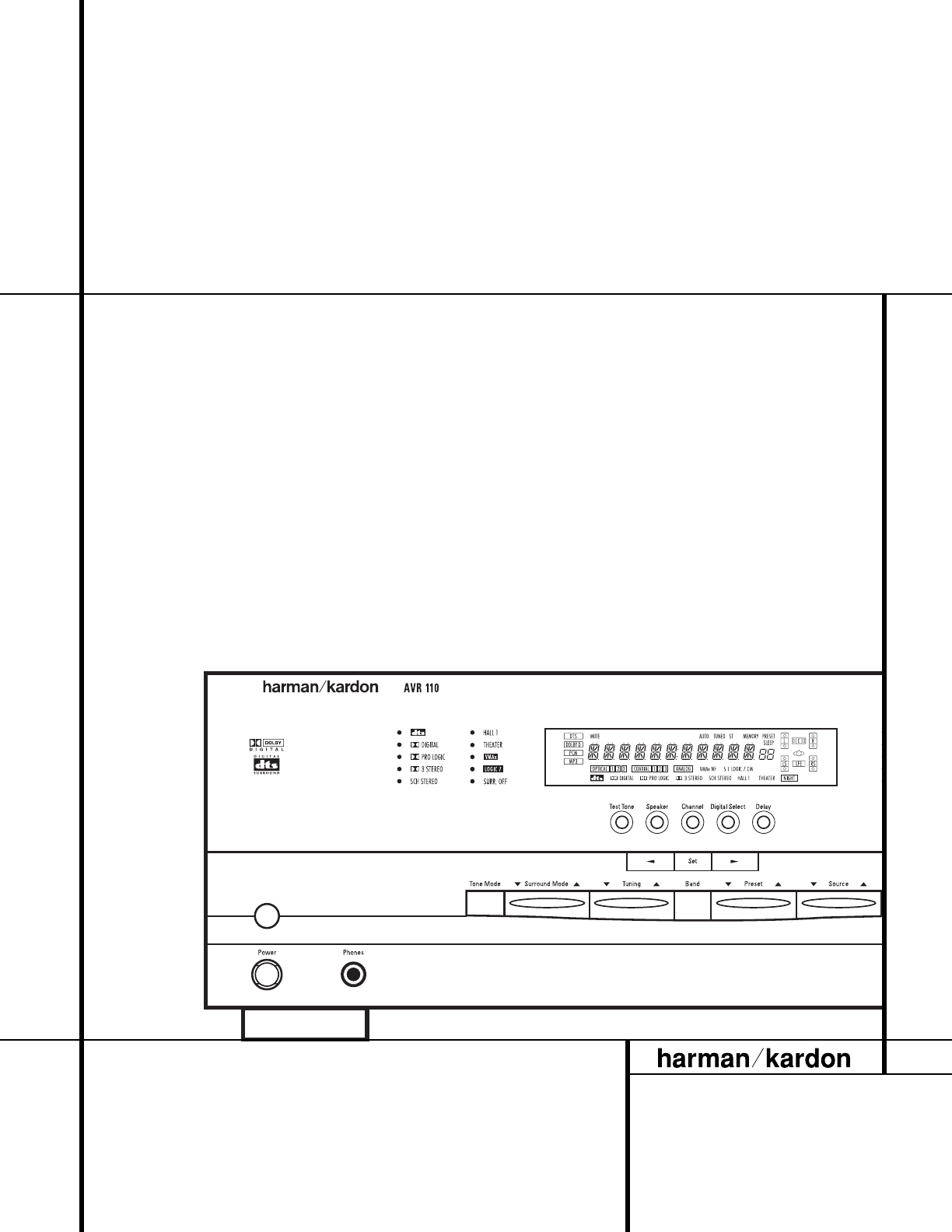
AVR 110 Audio/VideoReceiver
OWNER’S MANUAL
®
Power for the digital revolution.™
®

2TABLE OF CONTENTS
3Introduction
4Safety Information
4Unpacking
5Front Panel Controls
7Front Panel Information Display
9Rear Panel Connections
11 Remote Control Functions
14 Installation and Connections
16 System Configuration
16 Speaker Placement
17 System Setup
17 Speaker Configuration
18 Output Level Adjustment
19 Delay Settings
21 Operation
21 Basic Operation
21 Source Selection
22 Surround Mode Chart
23 Surround Mode Selection
23 Digital Audio Playback
23 Selecting a Digital Source
25 Tuner Operation
26 Tape Recording
26 Output Level Trim Adjustment
26 Display Brightness
27 Programming the Remote
27 Direct Code Entry
27 Auto Search Method
27 Code Readout
28 Macro Programming
28 Programmed Device Functions
29 Volume Punch-Through
29 Channel Control Punch-Through
29 Transport Control Punch-Through
30 Reassigning Device Control
Selectors
31 Function List
33 Setup Code Tables
43 Troubleshooting Guide
43 Processor Reset
44 Technical Specifications
AVR 110Audio/VideoReceiver
Typographical Conventions
In order to help you use this manual with the remote control, front panel controls and rear panel
connections, certain conventions have been used.
EXAMPLE – (bold type) indicates a specific remote control or front panel button, or rear panel
connection jack
EXAMPLE – (OCR type) indicates a message that is visible on the front panel information display
EXAMPLE – (outlined type) indicates a lit indicator in the front panel information display
1– (number in a square) indicates a specific front panel control
¡– (number in a circle) indicates a rear panel connection
a– (number in an oval) indicates a button or indicator on the remote
A– (letter in a square) indicates an indicator in the front panel display
3INTRODUCTION
Introduction
Thank you for choosing Harman Kardon!
With the purchase of a Harman Kardon
AVR 110, you are about to begin many years of
listening enjoyment.The AVR 110 has been
custom-designed to provide all the excitement
and detail of movie soundtracks and every
nuance of musical selections.With onboard
Dolby* Digital and DTS®decoding, the AVR 110
delivers six discrete channels of audio that take
advantage of the digital soundtracks from the
latest DVD and LD releases and Digital
Television broadcasts.
While complex digital systems are hard
at work within the AVR 110 to make all of this
happen, hookup and operation are simple.To
obtain the maximum enjoyment from your new
receiver, we urge you to take a few minutes to
read through this manual.This will ensure that
connections to speakers, source playback units
and other external devices are made properly.
In addition, a few minutes spent learning the
functions of the various controls will enable
you to take advantage of all the power the
AVR 110 is able to deliver.
If you have any questions about this product,
its installation or its operation,please contact
your retailer or custom installer.They are your
best local sources of information.
Description and Features
The AVR 110 is among the most versatile and
multi-featured A/V receivers available, incorpo-
rating a wide range of listening options. In
addition to Dolby Digital and DTS decoding for
digital sources, a broad choice of analog sur-
round modes are available for use with sources
such as CD,VCR,TV broadcasts and the
AVR 110’s FM/AM tuner.Along with Dolby
Pro Logic*, Dolby 3 Stereo and custom Hall and
Theater modes, only Harman Kardon receivers
offer Logic 7®to create a wider, more envelop-
ing field environment and more defined fly-
overs and pans.Another Harman Kardon exclu-
sive is VMAx®, which uses proprietary process-
ing to create an open, spacious sound field
even when only two front speakers are avail-
able. Finally, the AVR 110 is among the very
few A/V receivers that offer decoding of MP3
data, so that you may listen to the latest music
selections directly from compatible computers
or playback devices with the power and fidelity
you expect from Harman Kardon.
In addition to providing a wide range of
listening options, the AVR 110 is easy to
configure so that it provides the best results
with your speakers and specific listening-room
environment.
For the ultimate in flexibility,the AVR 110 fea-
tures connections for four video devices, all
with both composite and S-Video inputs.Two
additional audio inputs are available, and a
total of six digital inputs make the AVR 110
capable of handling all the latest digital audio
sources. Coax and optical digital outputs are
also available for direct connection to digital
recorders.The AVR 110’s powerful amplifier
uses traditional Harman Kardon high-current
design technologies to meet the wide dynamic
range of any program selection.
Harman Kardon invented the high-fidelity
receiver more than forty-seven years ago.With
state-of-the-art circuitry and time-honored cir-
cuit designs, the AVR 110 is one of the finest
receivers ever offered by Harman Kardon.
■Onboard Dolby Digital and DTS
Decoding Using Crystal®Chip
Technology
■Harman Kardon’s Exclusive Logic 7 and
VMAx Modes
■MP3 Decoding for Use With Computers
and Digital Audio Players
■Front Panel Digital Inputs for Easy
Connection to Portable Digital Devices
and the Latest Video Game Consoles
■Multiple Digital Inputs and Outputs
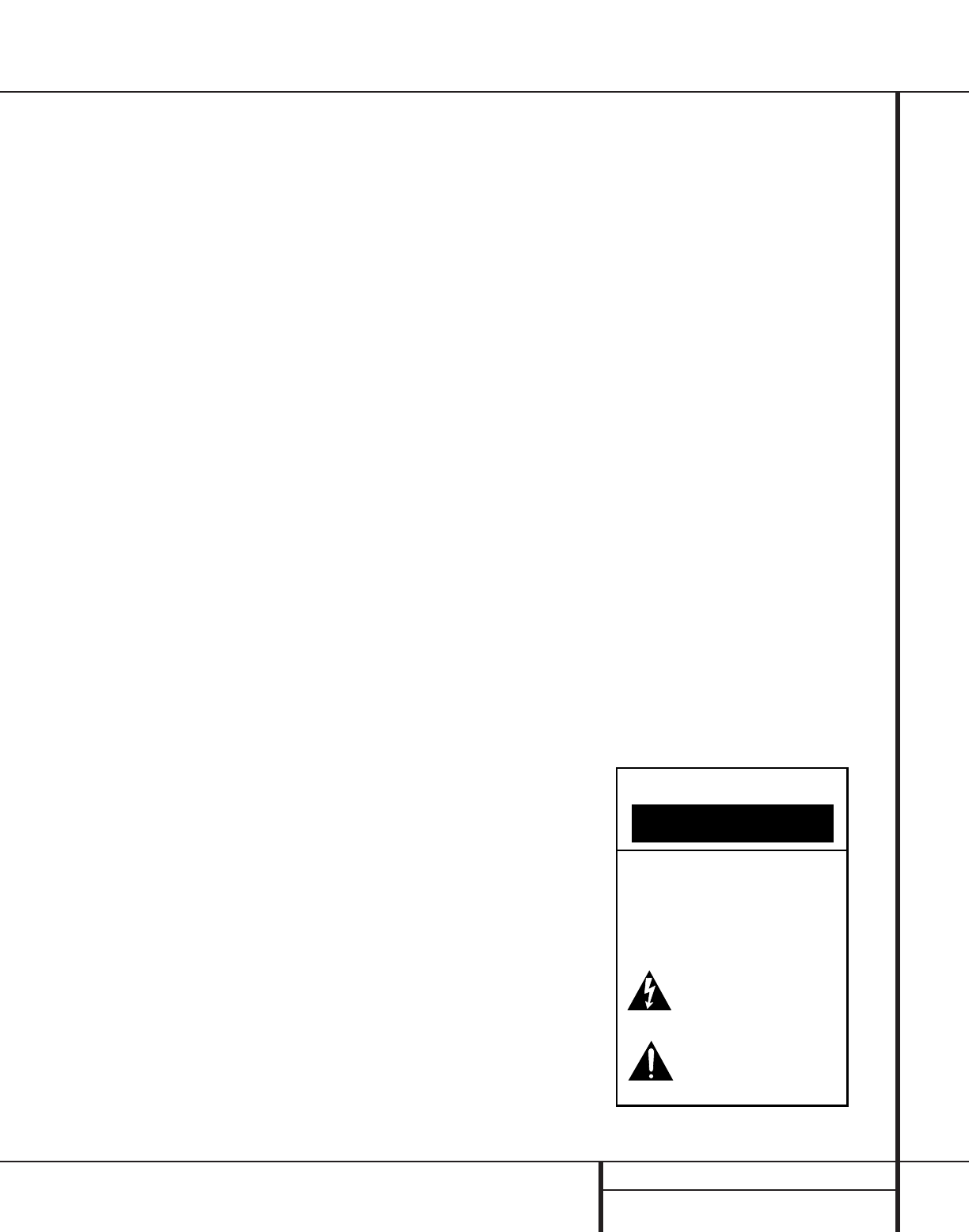
CAUTION
RISK OF ELECTRIC SHOCK
DO NOT OPEN
CAUTION: To prevent electric shock,
do not use this (polarized)
plug with an extension cord,
receptacle or other outlet
unless the blades can
be fully inserted to
prevent blade exposure.
The lightning flash with arrowhead symbol,
within an equilateral triangle, is intended to
alert the user to the presence of uninsulated
“dangerous voltage” within the product’s
enclosure that may be of sufficient magnitude to constitute a
risk of electric shock to persons.
The exclamation point within an equilateral
triangle is intended to alert the user to the
presence of important operating and
maintenance (servicing) instructions in the
literature accompanying the appliance.

4SAFETY INFORMATION
Safety Information
Important Safety Information
Verify Line Voltage Before Use
Your AVR 110 has been designed for use with
120-volt AC current. Connection to a line volt-
age other than that for which it is intended
can create a safety and fire hazard and may
damage the unit.
If you have any questions about the voltage
requirements for your specific model, or about
the line voltage in your area, contact your selling
dealer before plugging the unit into a wall outlet.
Do Not Use Extension Cords
To avoid safety hazards, use only the power
cord attached to your unit.We do not recom-
mend that extension cords be used with this
product.As with all electrical devices, do not
run power cords under rugs or carpets or place
heavy objects on them. Damaged power cords
should be replaced immediately by an author-
ized service depot with a cord meeting factory
specifications.
Handle the AC Power Cord Gently
When disconnecting the power cord from an
AC outlet,always pull the plug – never pull the
cord. If you do not intend to use the unit for
any considerable length of time, disconnect the
plug from the AC outlet.
Do Not Open the Cabinet
There are no user-serviceable components
inside this product. Opening the cabinet may
present a shock hazard, and any modification
to the product will void your guarantee. If water
or any metal object such as a paper clip, wire
or a staple accidentally falls inside the unit, dis-
connect it from the AC power source immedi-
ately, and consult an authorized service station.
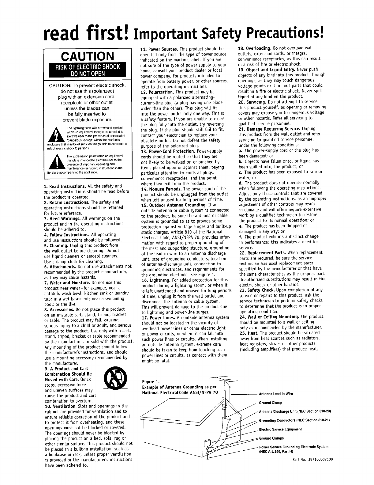
CATV or Antenna Grounding
If an outside antenna or cable system is con-
nected to this product, be certain that it is
grounded so as to provide some protection
against voltage surges and static charges.
Section 810 of the National Electrical Code,
ANSI/NFPA No. 70-1984, provides information
with respect to proper grounding of the mast
and supporting structure, grounding of the lead-
in wire to an antenna discharge unit, size of
grounding conductors, location of antenna dis-
charge unit, connection to grounding electrodes
and requirements of the grounding electrode.
NOTE TO CATV SYSTEM INSTALLER: This
reminder is provided to call the CATV (Cable
TV) system installer’s attention to article 820-
40 of the NEC that provides guidelines for
proper grounding and, in particular, specifies
that the cable ground shall be connected to the
grounding system of the building, as close to
the point of cable entry as possible.
Installation Location
■To ensure proper operation and to avoid the
potential for safety hazards, place the unit
on a firm and level surface.When placing the
unit on a shelf, be certain that the shelf and
any mounting hardware can support the
weight of the product.
■Make certain that proper space is provided
both above and below the unit for ventila-
tion. If this product will be installed in a
cabinet or other enclosed area, make certain
that there is sufficient air movement within
the cabinet. Under some circumstances,a
fan may be required.
■Do not place the unit directly on a carpeted
surface.
■Avoid installation in extremely hot or cold
locations, or in an area that is exposed to
direct sunlight or heating equipment.
■Avoid moist or humid locations.
■Do not obstruct the ventilation slots on the
top of the unit, or place objects directly
over them.
Cleaning
When the unit gets dirty, wipe it with a clean,
soft, dry cloth. If necessary, wipe it with a soft
cloth dampened with mild soapy water,then a
fresh cloth with clean water.Wipe dry immedi-
ately with a dry cloth. NEVER use benzene,
aerosol cleaners, thinner,alcohol or any other
volatile cleaning agent. Do not use abrasive
cleaners, as they may damage the finish of metal
parts.Avoid spraying insecticide near the unit.
Moving the Unit
Before moving the unit, be certain to discon-
nect any interconnection cords with other com-
ponents, and make certain that you disconnect
the unit from the AC outlet.
Important Information for the User
This equipment has been tested and found to
comply with the limits for a Class-B digital
device, pursuant to Part 15 of the FCC Rules.
The limits are designed to provide reasonable
protection against harmful interference in a
residential installation.This equipment gener-
ates,
uses and can radiate radio-frequency energy
and, if not installed and used in accordance
with the instructions, may cause harmful inter-
ference to radio communication.However, there
is no guarantee that harmful interference will
not occur in a particular installation. If this
equipment does cause harmful interference to
radio or television reception (which can be
determined by turning the equipment off and
on), the user is encouraged to try to correct the
interference by one or more of the following
measures:
■Reorient or relocate the receiving antenna.
■Increase the separation between the equip-
ment and receiver.
■Connect the equipment into an outlet on a
circuit different from that to which the
receiver is connected.
■Consult the dealer or an experienced
radio/TV technician for help.
This device complies with Part 15 of the FCC
Rules. Operation is subject to the following two
conditions: (1) this device may not cause harm-
ful interference, and (2) this device must accept
interference received, including interference
that may cause undesired operation.
NOTE: Changes or modifications may cause
this unit to fail to comply with Part 15 of the
FCC Rules and may void the user’s authority to
operate the equipment.
Unpacking
The carton and shipping materials used to pro-
tect your new receiver during shipment were
specially designed to cushion it from shock and
vibration.We suggest that you save the carton
and packing materials for use in shipping if you
move, or should the unit ever need repair.
To minimize the size of the carton in storage,
you may wish to flatten it.This is done by care-
fully slitting the tape seams on the bottom and
collapsing the carton. Other cardboard inserts
may be stored in the same manner. Packing
materials that cannot be collapsed should be
saved along with the carton in a plastic bag.
If you do not wish to save the packaging mate-
rials, please note that the carton and other sec-
tions of the shipping protection are recyclable.
Please respect the environment and discard
those materials at a local recycling center.
5FRONT PANEL CONTROLS
1Main Power Switch: Press this button to
apply power to the AVR 110.When the switch
is pressed in, the unit is placed in a Standby
mode, as indicated by the amber Power
Indicator 3surrounding the System
Power Control 2.This button MUST be
pressed in to operate the unit.To turn the unit
off and prevent the use of the remote control,
this switch should be pressed until it pops out
from the front panel so that the word “OFF”
may be read at the top of the switch.
NOTE: This switch is normally left in the “ON”
position.
2System Power Control: When the Main
Power Switch 1is “ON,” press this button
to turn on the AVR 110; press it again to turn
the unit off. Note that the Power Indicator
surrounding the switch 3will turn green
when the unit is on.
3Power Indicator: This LED will be illumi-
nated in amber when the unit is in the Standby
mode to signal that the unit is ready to be
turned on.When the unit is in operation,the
indicator will turn green.
4Headphone Jack:This jack may be used to
listen to the AVR 110’s output through a pair of
headphones. Be certain that the headphones
have a standard 1/4" stereo phone plug.Note
that the main room speakers will automatically
be turned off when the headphone jack is in use.
5Selector Buttons: When you are establish-
ing the AVR 110’s configuration settings, use
these buttons to select from the choices available,
as shown in the Main Information Display Û.
6Tone Mode: Pressing this button enables
or disables the Bass and Treble tone controls.
When the button is pressed so that the words
TONE IN appear in the Main Information
Display Û, the settings of the Bass &and
Treble (controls may be used to adjust the
output signals.When the button is pressed so
that the words TONE OUT appear in the Main
Information Display Û, the output signal
will be “flat,” without any bass or treble alter-
ation, no matter how the actual Bass and
Treble controls &( are adjusted.
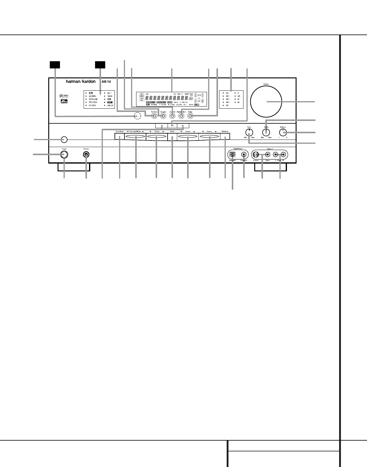
Front Panel Controls
1Main Power Switch
2System Power Control
3Power Indicator
4Headphone Jack
5Selector Buttons
6Tone Mode
7Surround Mode Selector
8Tuning Selector
9Tuner Band Selector
)Preset Stations Selector
!Input Source Selector
@FM Mode Selector
#Digital Optical 3 Input
$Digital Coax 3 Jack
%Video 4 Video Input Jacks
^Video 4 Audio Input Jacks
&Bass Control
*Balance Control
(Treble Control
ÓVolume Control
ÔSet Button
Input Indicators
ÒDelay
ÚDigital Input Selector
ÛMain Information Display
ÙChannel Select Button
ıSpeaker Select Button
ˆTest Tone Selector
˜Surround Mode Indicators
¯Remote Sensor Window
4
Ú
ı
1
35789)!@
#
$%^
*
&
(
Ó
29 Û Ô
2
6
30
Ò
ˆ Ù

6FRONT PANEL CONTROLS
Front Panel Controls
7Surround Mode Selector: Press this but-
ton to change the surround mode by scrolling
through the list of available modes. Note that
depending on the type of input, some modes
are not always available. (See page 23 for more
information about surround modes.)
8Tuning Selector: Press the left side of the
button to tune lower-frequency stations and the
right side of the button to tune higher-frequency
stations.When a station with a strong signal
is reached, the TUNED indicator Uwill be
illuminated in the Main Information
Display Û.
To tune manually,tap the button lightly and
note that the tuner will step up one frequency
increment per button press.When the button is
held for a few seconds you will note that the
unit will quickly search the frequency band.
Release it once the fast tuning starts; the tuner
will automatically scan for the next station with
an acceptable signal and then stop.
9Tuner Band Selector: Pressing this button
will automatically switch the AVR 110 to the
Tuner mode.Pressing it again will switch
between the AM and FM frequency bands. (See
page 25 for more information on the tuner.)
)Preset Stations Selector: Press this
button to scroll up or down through the list or
stations that have been entered into the preset
memory. (See page 26 for more information on
preset tuning.)
!Input Source Selector: Press this button
to change the input by scrolling up or down
through the list of input sources.
@FM Mode Selector: Press this button to
select Auto or Manual tuning.When the button
is pressed so that the AUTO indicator Vlights,
the tuner will search for the next station with an
acceptable signal when the Tuning Selector
8u is pressed.When the button is pressed
so that the AUTO indicator Vis not lit, each
press of the Tuning Selector 8u will
increase the frequency. (See page 25 for more
information on using the tuner.)
#Digital Optical 3 Input: Connect the opti-
cal digital output of an audio or video product to
this jack.When the Input is not in use,be certain
to keep the plastic cap installed to avoid dust
contamination that might degrade future
performance.
$Digital Coax 3 Jack:This jack is used for
connection to the output of portable audio
devices, video game consoles or other products
that have a coax digital jack.
%Video 4 Video Input Jacks:These jacks
may be used for temporary connection to the
composite or S-Video output of video games,
camcorders or other portable video products.
^Video 4 Audio Input Jacks: These
audio/video jacks may be used for temporary
connection to video games or portable
audio/video products such as camcorders and
portable audio players.
&Bass Control:Turn this control to modify
the low frequency output of the left/right chan-
nels by as much as ±10dB. Set this control to a
suitable position for your taste or room acoustics.
*Balance Control:Turn this control to
change the relative volume for the front
left/right channels.
NOTE: For proper operation of the surround
modes this control should be at the midpoint
or “12 o’clock” position.
(Treble Control:Turn this control to modify
the high frequency output of the left/right chan-
nels by as much as ±10dB. Set this control to a
suitable position for your taste or room acoustics.
ÓVolume Control: Turn this knob clockwise
to increase the volume, counterclockwise to
decrease the volume. If the AVR 110 is muted,
adjusting volume control will automatically
release the unit from the silenced condition.
ÔSet Button: When making choices during
the setup and configuration process, press this
button to enter the desired setting as shown
in the Main Information Display Ûinto the
AVR 110’s memory.The set button may also
be used to change the display brightness.
(See page 26.)
Input Indicators: A green LED will light
next to the name of the input that is currently
being used as the source for the AVR 110.
ÒDelay: Press this button to begin the
sequence of steps required to enter delay time
settings. (See page 19 for more information on
delay times.)
ÚDigital Input Selector: When playing a
source that has a digital output, press this
button to select between the Optical #g
and Coaxial $hDigital inputs. (See pages
23–25 for more information on digital audio.)
ÛMain Information Display: This display
delivers messages and status indications to
help you operate the receiver.(See pages 7–8
for a complete explanation of the Information
Display.)
ÙChannel Select Button: Press this button
to begin the process of trimming the channel
output levels using an external audio source.
(For more information on output level trim
adjustment, see page 26.)
ıSpeaker Select Button: Press this button
to begin the process of selecting the speaker
positions that are used in your listening room.
(See page 17 for more information on speaker
setup and configuration.)
ˆTest Tone Selector: Press this button to
begin the process of adjusting the channel out-
put levels using the internal test tone as a ref-
erence. (For more information on output level
adjustment, see page 26.)
˜Surround Mode Indicators: A green LED
will light next to the name of the surround
mode that is currently in use.
¯Remote Sensor Window:The sensor
behind this window receives infrared signals
from the remote control.Aim the remote at this
area and do not block or cover it unless an
external remote sensor is installed.
7FRONT PANEL INFORMATION DISPLAY
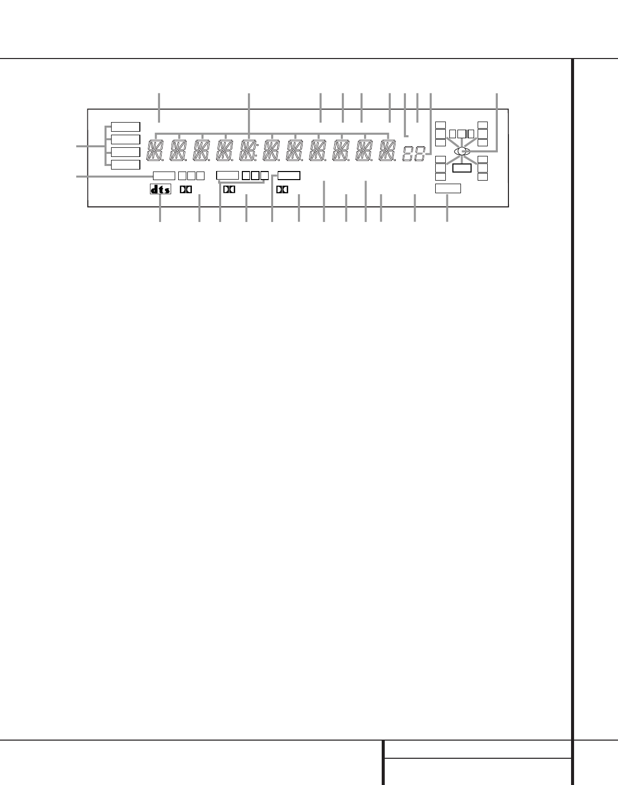
Front Panel Information Display
COAXIAL
THEATER
5 CH STEREO HALL 1
3
-
STEREO
PRO LOGIC
DIGITAL
DTS
DOLBY D
PCM
MP3
NIGHT
OPTICAL ANALOG LFE
0
CL
0
1 2 3 1 2 3
MEMORY PRESET
SLEEP
AUTO
5.1 LOGIC 7 CM
VMAx NF
MUTE TUNED ST
A
B
DEN
O
KM
L
S
TRQP
XWVU
FHIJ
O
O
R
O
O
LS
O
O
RS
O
O
CG
ABitstream Indicators
BOptical Source Indicators
CDTS Mode Indicator
DDolby Digital Indicator
ECoaxial Source Indicators
FDolby Pro Logic Indicator
GAnalog Input Indicator
HDolby 3 Stereo Indicator
IVMAx Mode Indicator
J5-Channel Stereo Indicator
KLogic 7 Mode Indicators
LHall Mode Indicator
MTheater Mode Indicator
NNight Mode Indicator
OSpeaker/Channel Input Indicators
PPreset Number/Sleep Timer
QPreset Indicator
RSleep Indicator
SMemory Indicator
TStereo Indicator
UTuned Indicator
VAuto Indicator
WMain Information Display
XMute Indicator
ABitstream Indicators:When the input is a
digital source, one of these indicators will light to
display the specific type of data signal in use.
BOptical Source Indicators:These indica-
tors light to show when an Optical Digital Input
has been selected.
CDTS Mode Indicator:This indicator lights
when a DTS-encoded source is playing.
DDolby Digital Indicator: This indicator
lights when a Dolby Digital source is playing.
ECoaxial Source Indicators:These indica-
tors light to show when a Coaxial Digital Input
has been selected.
FDolby Pro Logic Indicator:This indicator
lights when the Dolby Pro Logic mode has been
selected.
GAnalog Input Indicator: This indicator
lights when an analog input source has been
selected.
HDolby 3 Stereo Indicator:This indicator
lights when the Dolby 3 Stereo Mode has been
selected.
IVMAx Mode Indicator: This indicator
lights when the VMAx mode is in use. VMAx F
appears when the Far Field VMAx mode is
selected; VMAx N appears when the Near
Field VMAx mode is selected. (See page 22 for
a description of the VMAx modes.)
J5-Channel Stereo Indicator:This indica-
tor lights when the 5-Channel Stereo mode has
been selected.
KLogic 7 Mode Indicators:These indica-
tors light when the Logic 7 mode is in use.
LOGIC 7C appears for the Cinema version
of Logic 7; LOGIC 7M appears for the
Music version of Logic 7. (See page 22 for a
description of the Logic 7 modes.)
LHall Mode Indicator: This indicator lights
when the Hall mode has been selected.
MTheater Mode Indicator: This indicator
lights to show that the Theater mode has been
selected.
NNight Mode Indicator: This indicator
lights when the AVR 110 is in the Night mode,
which preserves the dynamic range of digital
program material at low volume levels.
OSpeaker/Channel Input Indicators:These
indicators are multipurpose, indicating either the
speaker type selected for each channel or the
incoming data-signal configuration.The left,
center, right, right surround and left surround
speaker indicators are composed of three boxes,
while the subwoofer is a single box.The center
box lights when a “Small” speaker is selected,
and all three boxes light when “Large” speakers
are selected.When none of the boxes are lit for
the center, surround or subwoofer channels,no
speaker has been selected for one of those posi-
tions. (See page 17 for more information on con-
figuring speakers.) The letters inside each of the
center boxes display active input channels. For
standard analog inputs, only the L and R will
light, indicating a stereo input.When a digital
source is playing, the indicators will light to dis-
play the channels being received at the digital
input.When the letters flash, the digital input
has been interrupted. (See page 18 for more
information on the Channel Indicators.)
PPreset Number/Sleep Timer: When the
tuner is in use, these numbers indicate the spe-
cific preset memory location in use. (See page
25 for more information on preset stations.)
When the Sleep function is in use, these num-
bers show how many minutes remain before
the unit goes into the Standby mode.
QPreset Indicator:This indicator lights
when the tuner is in use to show that the
Preset Number/Sleep Timer Pis showing
the station’s preset memory number. (See page
25 for more information on tuner presets.)
RSleep Indicator: This indicator lights when
the Sleep function is in use.The numbers in the
Preset Number/Sleep Timer Indicators will show
the minutes remaining before the AVR 110
goes into the Standby mode. (See page 21 for
more information on the Sleep function.)
8FRONT PANEL INFORMATION DISPLAY
Front Panel Information Display
S
Memory Indicator: This indicator flashes
when entering presets and other information
into the tuner’s memory.
TStereo Indicator:This indicator lights when
an FM station is being tuned in stereo.
U
Tuned Indicator:
This indicator lights when a
station is being received with sufficient signal
strength to provide acceptable listening quality.
VAuto Indicator: This indicator lights when
the tuner’s Auto mode is in use.
WMain Information Display: This display
shows messages relating to the status, input
source, surround mode, tuner, volume level or
other aspects of the AVR 110’s operation.
XMute Indicator: This indicator lights to
remind you that the AVR 110’s output has been
silenced by pressing the Mute button . Press
the Mute button again to return to the pre-
viously selected output level.
35
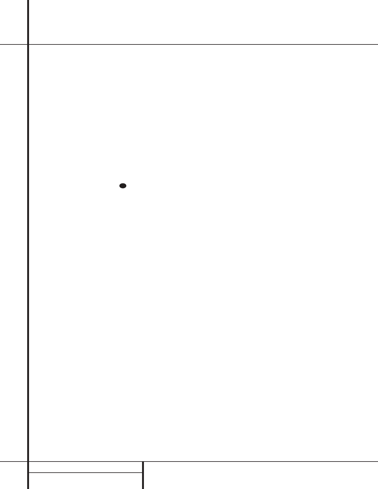
9REAR PANEL CONNECTIONS
Rear Panel Connections
⁄ ¤ ‹ › fi fl
°
a
b
c
d
e
f
g
j
‡
¢
§
•
h
k
‚
¡
™
£
∞
¶
ª
i
·
Manufactured under license from Dolby Laboratories.
"Dolby","Pro Logic" and the double-D symbol are trademarks
of Dolby Laboratories. Confidential Unpublished Works.
1992-1997 Dolby Laboratories,Inc. All rights reserved.
c
Manufactured under license from Digital Theater Systems, Inc. US Pat.
No. 5,451,942 and other world-wide patents issued and pending. "DTS",
"DTS Digital Surround", are trademarks of Digital Theater Systems, Inc.
Copyright 1996 Digital Theater Systems,Inc. All Rights Reserved.
This device complies with part 15 of the FCC rules. Operation is
subject to the following two conditions; (1) This device may not
cause harmful interference, and (2) This device must accept any
interference received, including interference that may cause
undesired operation.
REMOTE
U.S. Patent Nos.
4,893,342, 4,910,779, 4,975,954,
5,034,983, 5,136,651, and 5,333,200
Cooper Bauck Transaural Stereo.
¡Tape Inputs
™Tape Outputs
£Video 1 Audio Inputs
¢AM Antenna
∞Video 1 Audio Outputs
§DVD Audio Inputs
¶FM Antenna
•CD Inputs
ªDigital Audio Outputs
‚DVD Video Inputs
⁄Video Monitor Outputs
¤Subwoofer Output
‹Front Speaker Outputs
›Center Speaker Outputs
fiSurround Speaker Outputs
flSwitched AC Accessory Outlet
‡Unswitched AC Accessory Outlet
°AC Power Cord
·Remote IR Output
aRemote IR Input
bVideo 1 Video Outputs
cVideo 1 Video Inputs
dVideo 3 Video Inputs
eVideo 2 Video Inputs
fVideo 2 Video Outputs
gOptical Digital Inputs
hCoaxial Digital Inputs
iVideo 2 Audio Outputs
jVideo 3 Audio Inputs
kVideo 2 Audio Inputs

10 REAR PANEL CONNECTIONS
Rear Panel Connections
¡Tape Inputs: Connect these jacks to the
PLAY/OUT jacks of an audio recorder.
™Tape Outputs: Connect these jacks to the
RECORD/INPUT jacks of an audio recorder.
£Video 1 Audio Inputs: Connect these
jacks to the PLAY/OUT audio jacks on a VCR
or other video source.
¢AM Antenna: Connect theAM loop antenna
supplied with the receiver to these terminals. If an
externalAM antenna is used,make connections
to the AM and GND terminals in accordance
with the instructions supplied with the antenna.
∞Video 1 Audio Outputs: Connect these
jacks to the RECORD/INPUT audio jacks on
a VCR.
§DVD Audio Inputs: Connect these jacks
to the analog audio jacks on a DVD or other
video source.
¶FM Antenna: Connect the supplied indoor or
an optional external FM antenna to this terminal.
•CD Inputs: Connect these jacks to the out-
put of a compact disc player or CD changer.
ªDigital Audio Outputs: Connect these
jacks to the matching digital input connector
on a digital recorder such as a CD-R or
MiniDisc recorder.
‚DVD Video Inputs: Connect these jacks to
the composite or S-Video output jacks on a
DVD or other video source.
⁄Video Monitor Outputs: Connect this
jack to the composite or S-Video input of a TV
monitor or video projector to view the output
of any standard video source selected by the
receiver’s video switcher.
¤Subwoofer Output: Connect this jack to
the line-level input of a powered subwoofer. If
an external subwoofer amplifier is used, con-
nect this jack to the subwoofer amplifier input.
‹Front Speaker Outputs: Connect these
outputs to the matching + and – terminals on
your front left/right speakers.
›Center Speaker Outputs: Connect these
outputs to the matching + and – terminals on
your center-channel speaker.
fiSurround Speaker Outputs: Connect
these outputs to the matching + and – termi-
nals on your left and right surround speakers.
NOTE: When making speaker connections
always make certain to maintain correct polarity
by connecting the red (+) terminals on the
AVR 110 to the red (+) terminals on the speak-
ers and the black (–) terminals on the AVR 110
to the black (–) terminals on the speakers.
See page 14 for more information on speaker
polarity.
flSwitched AC Accessory Outlet:This
outlet may be used to power any device you
wish to have turned on when the AVR 110 is
turned on with the System Power Control
switch 2.
‡Unswitched AC Accessory Outlet:This
outlet may be used to power any AC device.
The power will remain on at this outlet regard-
less of whether the AVR 110 is on or off.
NOTE: The total power consumption of all
devices connected to the accessory outlets
should not exceed 100 watts.
°AC Power Cord: Connect the AC plug to
an unswitched AC wall output.
·Remote IR Output: This connection per-
mits the IR sensor in the receiver to serve other
remote controlled devices. Connect this jack to
the “IR IN” jack on Harman Kardon (or other
compatible) equipment.
aRemote IR Input: If the AVR 110’s front
panel IR sensor is blocked due to cabinet
doors or other obstructions, an external IR
sensor may be used. Connect the output of
the sensor to this jack.
bVideo 1 Video Outputs: Connect these
jacks to the RECORD/INPUT composite or
S-Video jack on a VCR.
cVideo 1 Video Inputs: Connect these
jacks to the PLAY/OUT composite or S-Video
jacks on a VCR or other video source.
dVideo 3 Video Inputs: Connect these
jacks to the PLAY/OUT composite or S-Video
jacks on a VCR or other video source.
eVideo 2 Video Inputs: Connect these
jacks to the PLAY/OUT composite or S-Video
jacks on a VCR or other video source.
fVideo 2 Video Outputs: Connect these
jacks to the RECORD/INPUT composite or
S-Video jacks on a VCR.
gOptical Digital Inputs: Connect the opti-
cal digital output from a DVD player, HDTV
receiver, LD player or CD player to these jacks.
The signal may be either a Dolby Digital signal,
a DTS signal or a standard PCM digital source.
hCoaxial Digital Inputs: Connect the coax
digital output from a DVD player, HDTV receiver,
LD player or CD player to these jacks.The signal
may be either a Dolby Digital signal, DTS signal
or a standard PCM digital source. Do not con-
nect the RF digital output of an LD player to
these jacks.
iVideo 2 Audio Outputs: Connect these
jacks to the RECORD/INPUT audio jacks on a
VCR or other video source.
jVideo 3 Audio Inputs: Connect these
jacks to the PLAY/OUT audio jacks on a VCR
or other video source.
kVideo 2 Audio Inputs: Connect these
jacks to the PLAY/OUT audio jacks on a VCR
or other video source.
11 REMOTE CONTROL FUNCTIONS
●
●
●
●
●
●
●
●
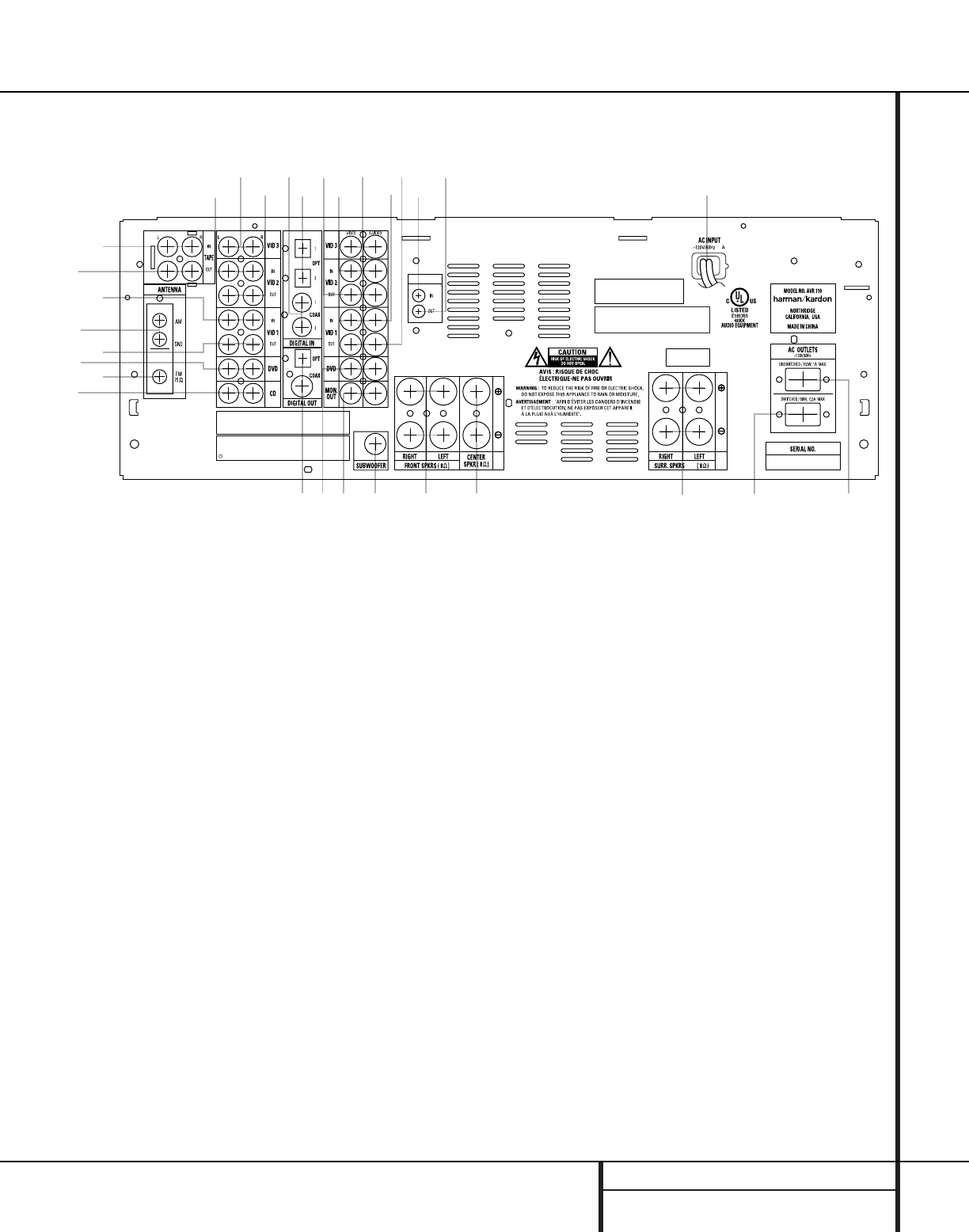
Remote Control Functions
s
a
bc
d
e
f
g
h
i
j
k
n
p
o
qr
t
v
w
`
32
30
29
28
35
34
33
31
z
x
y
POWER
MUTE
AVR
DVD
AM/FM
CD TAPE
VID 2
VCR TV CBL/SAT VID 4VID 1 VID 3
OFF ON
SLEEP T/V
SURR.
CH. VOL.
G
U
I
D
E
C
H
.
E
X
I
T
D
I
G
I
T
A
L
M
E
N
U
S
P
K
R
P
R
E
V
.
C
H
.
D
E
L
A
Y
SET
1234
7
6
5
90
TUN-M MEM
M2 M3 M4
D.SKIP
M1
DIRECT
TUNING PRESET
CLEAR
DWN UP
TEST
NIGHT
110
8
SKIP
l
m
u
aPower On Button
bIR Transmitter Window
cProgram Indicator
dPower Off Button
eInput Selectors
fAVR Selector
gAM/FM Tuner Select
hTest Button
iSleep Button
jSurround Mode Selector
kNight Mode
lChannel Select Button
m
⁄
Button
n
‹
Button
oSet Button
pDigital Select
q
¤
Button
rNumeric Keys
sTuner Mode
tDirect Button
uTuning Up/Down
vMacro Buttons
wTransport Controls
xSkip Up/Down Buttons
yDisc Skip Buttons
zPreset Up/Down
`Clear Button
28
Memory Button
29
Delay/Prev. Ch.
30
›
Button
31
Speaker Select
32
Spare Button
33
Volume Up/Down
34
TV/Video Selector
35
Mute
NOTE: The function names shown here are each
button’s feature when used with the AVR 110.
Most buttons have additional functions when
used with other devices. See pages 31–32 for a
list of these functions.
12 REMOTE CONTROL FUNCTIONS
Remote Control Functions
IMPORTANT NOTE:The AVR 110’s remote
may be programmed to control up to eight
devices, including the AVR 110.Before using the
remote, it is important to remember to press the
Input Selector button ethat corresponds to
the unit you wish to operate. In addition, the
AVR 110’s remote is shipped from the factory to
operate the AVR 110 and most Harman Kardon
CD or DVD players and cassette decks.The
remote is also capable of operating a wide vari-
ety of other products using the control codes
that are part of the remote. Before using the
remote with other products, follow the instruc-
tions on pages 27–29 to program the proper
codes for the products in your system.
It is also important to remember that many of
the buttons on the remote take on different
functions, depending on the product selected
using the Input Selectors eg.The
descriptions shown here primarily detail the
functions of the remote when it is used to oper-
ate the AVR 110. (See page 30 for information
about alternate functions for the remote’s but-
tons.)
aPower On Button: Press this button to
turn on the power to a device selected by press-
ing one of the Input Selectors e.
bIR Transmitter Window: Point this win-
dow towards the AVR 110 when pressing buttons
on the remote to make certain that infrared com-
mands are properly received.
cProgram Indicator:This LED indicator is
used to guide you through the process of pro-
gramming the remote. (See page 27 for infor-
mation on programming the remote.)
dPower Off Button: Press this button to
place the AVR 110 or a selected device in the
Standby mode.
eInput Selectors: Pressing one of these
buttons will perform three actions at the same
time. First, if the AVR 110 is not turned on, this
will power up the unit. Next, it will select the
source shown on the button as the input to the
AVR 110. Finally, it will change the remote con-
trol so that it controls the device selected.After
pressing one of these buttons you must press
the AVR Selector button fagain to oper-
ate the AVR 110’s functions with the remote.
fAVR Selector: Pressing this button will
switch the remote so that it will operate the
AVR 110’s functions. If the AVR 110 is in the
Standby mode, it will also turn the AVR110 on.
gAM/FM Tuner Select: Press this button to
select the AVR 110’s tuner as the listening
choice. Pressing this button when the tuner is
already in use will select between the AM and
FM bands.
hTest Button: Press this button to begin
the sequence used to calibrate the AVR 110’s
output levels. (See page 18 for more information
on calibrating the AVR 110.)
iSleep Button: Press this button to place
the unit in the Sleep mode.After the time
shown in the display, the AVR 110 will auto-
matically go into the Standby mode. Each press
of the button changes the time until turn-off in
the following order:
Note that this button is also used to change
channels on your TV when the TV is selected.
When the AVR 110 remote is being programmed
with the codes to operate another device, this
button is also used in the “Auto Search” process.
(See page 27 for more information on program-
ming the remote.)
jSurround Mode Selector: Press this
button to begin the process of changing
the surround mode. After the button has
been pressed, use the ⁄/¤buttons mq
to select the desired surround mode. (See page
23 for more information.) Note that this button
is also used to tune channels when the TV is
selected using the device Input Selector
e. When the AVR 110 remote is being pro-
grammed with the codes of another device, this
button is also used in the “Auto Search”
process. (See page 27 for more information on
programming the remote.)
kNight Mode: Press this button to activate
the Night mode.This mode is available in spe-
cially encoded digital sources, and it preserves
dialog (center-channel) intelligibility at low
volume levels.
lChannel Select Button:This button is
used to start the process of setting the AVR 110’s
output levels to an external source. Once this but-
ton is pressed,use the ⁄/¤buttons mq to
select the channel being adjusted, then press the
Set button o, followed by the ⁄/¤buttons
mq again,to change the level setting.(See
page 18 for more information.)
m⁄Button:This multipurpose button is
used to change or scroll through items in the on
screen menus, or to change configuration set-
tings such as output levels.When changing an
item such as the surround mode or digital input
directly, first press the function or mode to be
changed (e.g., press the Surround Mode j
to select a surround mode or the Digital button
pto change the digital input) and then press
this button to scroll through the list of available
choices.
n‹Button:This button is used to change
the menu selection or setting during some of
the setup procedures for the AVR 110.
oSet Button:This button is used to enter
settings into the AVR 110’s memory. It is also
used in the setup procedures for delay time,
speaker configuration and channel output level
adjustment.
pDigital Select: Press this button to assign
one of the digital inputs gh$to a source.
(See page 23 for more information on using
digital inputs.)
q¤Button:This multi-purpose button is
used to change or scroll through items in the on
screen menus, or to change configuration set-
tings such as output levels.When changing an
item such as the surround mode or digital input
directly, first press the function or mode to be
changed (e.g., press the Surround Mode j
to select a surround mode or the Digital button
pto change the digital input) and then press
this button to scroll through the list of available
choices.
rNumeric Keys: These buttons serve as a
ten-button numeric keypad to enter tuner preset
positions.They are also used to select channel
numbers when TV has been selected on the
remote, or to select track numbers on a CD,
DVD or LD player, depending on how the
remote has been programmed.
sTuner Mode: Press this button when the
tuner is in use to select between automatic
tuning and manual tuning.When the button is
pressed so that the AUTO indicator Vgoes
out, pressing the Tuning buttons u8 will
move the frequency up or down in single-step
increments.When the FM band is in use, press-
ing this button when a station’s signal is weak
will change to monaural reception.(See page
25 for more information.)
90
min 80
min 70
min 60
min 50
min
40
min 30
min 20
min 10
min OFF
13 REMOTE CONTROL FUNCTIONS
tDirect Button: Press this button when
the tuner is in use to start the sequence for
direct entry of a station’s frequency.After press-
ing the button simply press the proper
Numeric Keys rto select a station. (See
page 25 for more information on the tuner.)
uTuning Up/Down:When the tuner is in
use, these buttons will tune up or down through
the selected frequency band. If the Tuner Mode
button s@ has been pressed so that the
AUTO indicator Vis illuminated, pressing and
holding either of the buttons for three seconds
will cause the tuner to seek the next station with
acceptable signal strength for quality reception.
When the AUTO indicator Vis NOT illumi-
nated, pressing these buttons will tune stations
in single-step increments. (See page 25 for more
information.)
vMacro Buttons: Press these buttons
to store or recall a “Macro”, which is a
preprogrammed sequence of commands
stored in the remote. (See page 28 for more
information on storing and recalling macros.)
wTransport Controls: These buttons do
not have any functions for the AVR 110, but
they may be programmed for the forward/
reverse play operation of a wide variety of CD
or DVD players, and audio or video cassette
recorders. (See page 27 for more information
on programming the remote.)
xSkip Up/Down Buttons: These buttons
do not have a direct function with the AVR 110,
but when used with a compatibly programmed
CD or DVD changer they will change the disc
currently being played in the changer.
yDisc Skip Buttons:These buttons have
no direct function for the AVR 110, but they are
often used when the remote is programmed to
operate a CD or DVD changer to change the
discs in the changer. (See page 30 for more
information on using the remote with other
devices.)
zPreset Up/Down:When the tuner is
in use, press these buttons to scroll through the
stations programmed into the AVR 110’s mem-
ory.When some source devices,such as CD
players,VCRs and cassette decks, are selected
using the device Input Selectors e, these
buttons may function as Chapter Step or Track
Advance.
`Clear Button: Press this button to clear
incorrect entries when using the remote to
directly enter a radio station’s frequency.
Memory Button: Press this button to
enter a radio station into the AVR 110’s preset
memory. Once the MEMORY indicator S
flashes, you have five seconds to enter a preset
memory location using the Numeric Keys
r. (See page 26 for more information.)
Delay/Prev Ch.: Press this button to
begin the process for setting the delay times
used by the AVR 110 when processing surround
sound.After pressing this button, the delay
times are entered by pressing the Set button
oand then using the ⁄/¤buttons mq
to change the setting. Press the Set button
oagain to complete the process. (See page
19 for more information.)
›Button: Press this button to change a
setting or selection when configuring many of the
AVR 110’s settings.
Speaker Select: Press this button
to begin the process of configuring the
AVR 110’s bass management system for the
type of speakers used in your system. Once the
button has been pressed, use the ⁄/¤but-
tons mq to select the channel you wish to
set up. Press the Set button oand then
select another channel to configure.When all
adjustments have been completed, press the
Set button otwice to exit the settings and
return to normal operation. (See page 17 for
more information.)
Spare Button:This button does not have
any function for the operation of the AVR 110,
but it is available for use to be programmed for
a function from another remote.
Volume Up/Down: Press these buttons to
raise or lower the system volume.
TV/Video Button: This button does not
have a direct function on the AVR 110, but
when used with a compatibly programmed
VCR, DVD or satellite receiver that has a
“TV/Video”function, pressing this button will
switch between the output of the player or
receiver and the external video input to that
player. Consult the owner’s manual for your
specific player or receiver for the details of how
it implements this function.
Mute: Press this button to momentarily
silence the AVR 110 or TV set being controlled,
depending on which device has been selected.
When the AVR 110 remote is being programmed
to operate another device, this button is pressed
with the Input Selector button eto begin
the programming process. (See page 27 for
more information on programming the remote.)
35
34
33
32
31
30
29
28
Remote Control Functions
14 INSTALLATION AND CONNECTIONS
System Installation
After unpacking the unit, and placing it on a solid
surface capable of supporting its weight, you will
need to make the connections to your audio and
video equipment.
Audio Equipment Connections
We recommend that you use high-quality inter-
connect cables when making connections to
source equipment and recorders to preserve the
integrity of the signals.
When making connections to audio source
equipment or speakers it is always a good prac-
tice to unplug the unit from the AC wall outlet.
This prevents any possibility of accidentally
sending audio or transient signals to the speak-
ers that may damage them.
1. Connect the analog output of a CD player to
the CD inputs •.
NOTE: When the CD player has both fixed and
variable audio outputs it is best to use the fixed
output unless you find that the input to the
receiver is so low that the sound is noisy, or so
high that the signal is distorted.
2. Connect the analog Play/Out jacks of a cas-
sette deck, MD,CD-R or other audio recorder to
the Tape Input jacks ¡. Connect the analog
Record/In jacks on the recorder to the Tape
Output jacks ™on the AVR 110.
3. Connect the output of any digital sources
to the appropriate input connections on the
AVR 110 rear panel. Note that the Optical
and Coaxial Digital Inputs gh#$ may
be used with a Dolby Digital or DTS source or
the output of a conventional CD or LD player’s
PCM (S/P-DIF) output.
4.Connect the Coaxial or Optical Digital
Outputs ªon the rear panel of the AVR 110 to
the matching digital input connections on a CD-R
or MiniDisc recorder.
5.Assemble the AM Loop Antenna supplied
with the unit as shown below. Connect it to the
AM and GND screw terminals ¢.
6. Connect the supplied FM antenna to the FM
(75 ohm) connection ¶.The FM antenna may
be an external roof antenna, an inside powered
or wire lead antenna or a connection from a
cable TV system. Note that if the antenna or
connection uses 300-ohm twin-lead cable, you
must use the 300-ohm-to-75-ohm adapter sup-
plied with the unit to make the connection.
7. Connect the front, center and surround
speaker outputs ‹›fi to the respective
speakers.
To ensure that all the audio signals are carried
to your speakers without loss of clarity or reso-
lution, we suggest that you use high-quality
speaker cable. Many brands of cable are avail-
able and the choice of cable may be influenced
by the distance between your speakers and the
receiver, the type of speakers you use, personal
preferences and other factors.Your dealer or
installer is a valuable resource to consult in
selecting the proper cable.
Regardless of the brand of cable selected,we
recommend that you use a cable constructed of
fine, multistrand copper with a gauge of 14 or
smaller. Remember that in specifying cable,the
lower the AWG number, the thicker the cable.
Cable with a gauge of 16 may be used for short
runs of less than ten feet.We do not recom-
mend that you use cables with an AWG equiva-
lent of 18 or higher due to the power loss and
degradation in performance that will occur.
Cables that are run inside walls should have the
appropriate markings to indicate listing with UL,
CSA or other appropriate testing agency stan-
dards. Questions about running cables inside
walls should be referred to your installer or a
licensed electrical contractor who is familiar
with the NEC and/or the applicable local build-
ing codes in your area.
When connecting wires to the speakers, be cer-
tain to observe proper polarity. Remember to
connect the “negative” or “black” wire to the
same terminal on both the receiver and the
speaker. Similarly, the “positive” or “red” wire
should be connected to like terminals on the
AVR 110 and speaker.
NOTE: While most speaker manufacturers
adhere to an industry convention of using black
terminals for negative and red ones for positive,
some manufacturers may vary from this config-
uration.To assure proper phase and optimal
performance, consult the identification plate on
your speaker or the speaker’s manual to verify
polarity. If you do not know the polarity of your
speaker, ask your dealer for advice before pro-
ceeding, or consult the speaker’s manufacturer.
We also recommend that the length of cable
used to connect speaker pairs be identical.
For example, use the same length piece of
cable to connect the front-left and front-right
or surround-left and surround-right speakers,
even if the speakers are a different distance
from the AVR 110.
8. Connections to a subwoofer are normally
made via a line-level audio connection from the
Subwoofer Output ¤to the line-level input
of a subwoofer with a built-in amplifier.When a
passive subwoofer is used, the connection first
goes to a power amplifier, which will be con-
nected to one or more subwoofer speakers. If
you are using a powered subwoofer that does
not have line-level input connections, follow the
instructions furnished with the speaker for con-
nection information.
Video Equipment Connections
Video equipment is connected in the same man-
ner as audio components.Again, the use of high-
quality interconnect cables is recommended to
preserve signal quality.
1. Connect a VCR’s or other video source’s
audio and video Play/Out jacks to the Video 1
or Video 2 In jacks £cek on the rear
panel.The Audio and Video Record/In jacks on
the VCR should be connected to the Video 1
or Video 2 Out jacks ∞bfi on the
AVR 110.
2. Connect the analog audio and video outputs
of a satellite receiver, cable TV converter or
television set or any other video source to the
Video 3 jacks dj.
3. Connect the analog audio and video
outputs of a DVD or laser disc player to the
DVD jacks §‚.
4. Connect the digital audio outputs of a DVD
player, satellite receiver, cable box or HDTV con-
verter to the appropriate Optical or Coaxial
Digital Inputs gh#$.
5. Connect the Video Monitor Output ⁄
jacks on the receiver to the composite or
S-Video input of your television monitor or
video projector.
Installation and Connections

15 INSTALLATION AND CONNECTIONS
Installation and Connections
VIDEO CONNECTION NOTE: Composite
video signals may only be viewed in their native
formats. S-Video inputs may only be viewed
when the AVR 110 is connected to a TV set or
video display with S-Video capability.
System and Power Connections
Remote Control Extension
If the receiver is placed behind a solid or
smoked glass cabinet door, the obstruction may
prevent the remote sensor from receiving com-
mands. In this event, an optional remote sensor
may be used. Connect the output of the remote
sensor to the Remote IR Input jack a.
If other components are also prevented from
receiving remote commands, only one sensor is
needed. Simply use this unit’s sensor or a
remote eye by running a connection from the
Remote IR Output jack ·to the Remote
IR Input jack on Harman Kardon or other com-
patible equipment.
IMPORTANT NOTE: Any cables run inside walls
should be CL3/FT4 rated,or carry any other certi-
fication that is required by the NEC or state and
local building and electrical codes.To avoid inter-
ference, audio and speaker cables should not be
parallel to, or run in the same conduits or path
with,AC cables. If you have any questions about
multiroom wiring, consult your dealer, custom
installer or low-voltage electrical contractor.
AC Power Connections
This unit is equipped with two accessory AC
outlets.They may be used to power accessory
devices, but they should not be used with high-
current draw equipment such as power ampli-
fiers.The total power draw to each outlet may
not exceed 100 watts.
The Switched AC Accessory outlet flwill
receive power only when the unit is on.This is
recommended for devices that have no power
switch or a mechanical power switch that may
be left in the “ON” position.
NOTE: Many audio and video products go into
a Standby mode when they are used with
switched outlets, and cannot be fully turned on
using the outlet alone without a remote control
command.
The Unswitched AC Accessory outlet ‡will
receive power as long as the unit is plugged
into a powered AC outlet.
Finally, when all connections are complete, plug
the power cord into a nonswitched 110-volt AC
wall outlet.You’re almost ready to enjoy the
AVR 110!
16 SYSTEM CONFIGURATION
System Configuration
When all audio, video and system connections
have been made, there are a few configuration
adjustments that must be made.A few minutes
spent to correctly configure and calibrate the
unit will greatly add to your listening experience.
Speaker Selection and Placement
The placement of speakers in a multichannel
home-theater system can have a noticeable
impact on the quality of sound reproduced.
No matter which type or brand of speakers is
used, the same model or brand of speaker
should be used for the left front, center and
right front speakers.This creates a seamless
front soundstage and eliminates the possibility
of distracting sonic disturbances that occur
when a sound moves across mismatched
front-channel speakers.
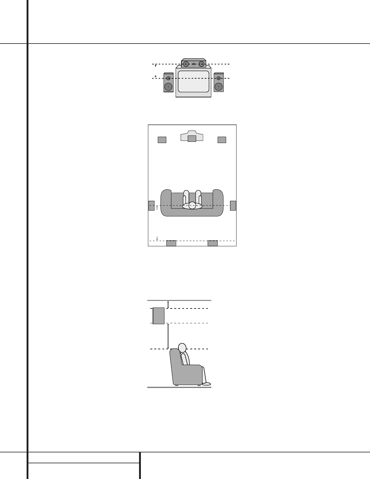
Speaker Placement
Depending on the type of center-channel
speaker in use and your viewing device, place
the center speaker either directly above or
below your TV, or in the center behind a perfo-
rated front projection screen.
Once the center-channel speaker is installed,
position the left front and right front speakers
so that they are as far away from one another
as the center-channel speaker is from the pre-
ferred listening position. Ideally, the front-channel
speakers should be placed so that their tweeters
are no more than 24" above or below the
tweeter in the center-channel speaker.
Depending on the specifics of your room
acoustics and the type of speakers in use, you
may find that imaging is improved by moving
the left front and right front speakers slightly
forward of the center-channel speaker. If possi-
ble, adjust all front loudspeakers so that they
are aimed at ear height when you are seated
in the listening position.
Using these guidelines, you’ll find that it takes
some experimentation to find the correct loca-
tion for the front speakers in your particular
installation. Don’t be afraid to move things
around until the system sounds correct. Optimize
your speakers so that audio transitions across
the front of the room sound smooth, and that
sounds from all speakers appear to arrive at the
listening position at the same time (without
delay from the center speaker compared to the
left and right speakers).
Surround speakers should be placed on the side
walls of the room,at or slightly behind the
listening position.The center of the speaker
should face into the room.The speakers should
be located so that the bottom of the cabinet
is at least two feet higher than the listeners’
ears when the listeners are seated in the
desired area.
If side-wall mounting is not practical, the
speakers may be placed on a rear wall, behind
the listening position.Again, they should be
located so that the bottom of the cabinet is at
least two feet higher than the listeners’ ears.
The speakers should be no more than six feet
behind the rear of the seating area.
Subwoofers produce nondirectional sound, so
they may be placed almost anywhere in a
room.Actual placement should be based on
room size and shape and the type of subwoofer
used. One method of finding the optimal loca-
tion for a subwoofer is to begin by placing it in
the front of the room, about six inches from a
wall, or near the front corner of the room.
Another method is to temporarily place the
subwoofer at your normal listening position,
and then walk around the room until you find
a spot where the subwoofer sounds best. Place
the subwoofer in that spot.You should also
follow the instructions of the subwoofer’s man-
ufacturer, or you may wish to experiment with
the best location for a subwoofer in your lis-
tening room.
Once the speakers have been placed in the
room and connected, the remaining steps
in the setup process are to program the
AVR 110’s bass management system for the
type of speakers used in your system, calibrate
the output levels, and set the delay times used
by the surround-sound processor.
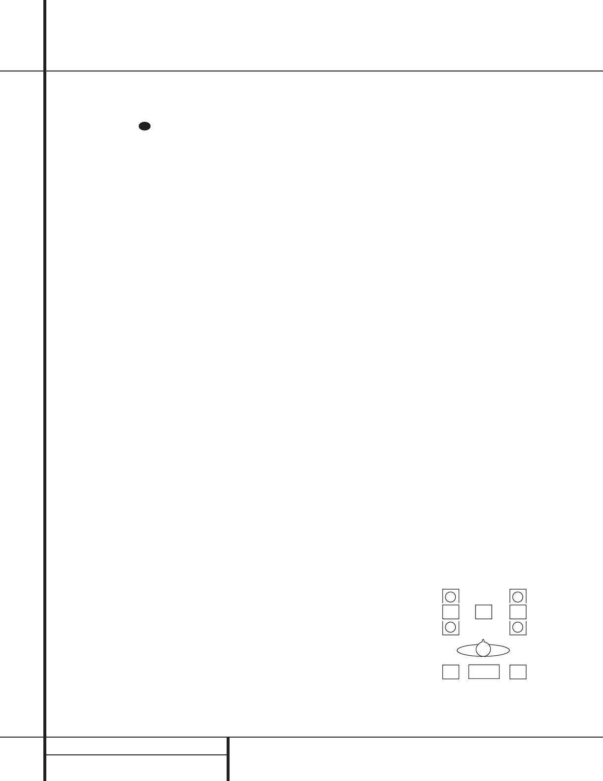
Right Front
Speaker
Left Front
Speaker
No more
than 24"
Center Front Speaker
At least 2 feet
At least 6 inches from ceiling
A) Front-Channel Speaker Installation with
Direct-View TV Sets or Rear-Screen Projectors
Center Front
Speaker
Optional Rear-Wall Mounting
TV or Projection Screen
Right Front
Speaker
Left Front
Speaker
No more than 6 feet
when rear-mounted
speakers are used
B) The distance between the left and right
speakers should be equal to the distance
from the seating position to the viewing
screen. You may also experiment with plac-
ing the left and right speakers slightly for-
ward of the center speaker.
17 SYSTEM CONFIGURATION
System Configuration
System Setup
Once the speakers have been placed in the
room and connected, the remaining steps in
the setup process are to program the AVR 110’s
bass management system for the type of
speakers used in your system, calibrate the
output levels, and set the delay times used by
the surround-sound processor.
The AVR 110 features an advanced memory
system that enables you to establish different
configurations for the speaker configuration,
surround mode, delay times, and output levels
for each input source.This flexibility enables
you to custom-tailor the way in which you lis-
ten to each source and have the AVR 110
memorize those settings.This means, for exam-
ple, that you may use different output levels or
trims for different sources, or set different
speaker configurations with the resultant
changes to the bass management system. Once
these settings are made, they will automatically
be recalled whenever you select that input.
The factory default settings for the AVR 110
have all inputs configured for an analog source,
stereo as the surround mode, the front left and
right speakers set to “large,” and a subwoofer
connected. Before using the unit, you will prob-
ably want to change the settings for most
inputs so that they are properly configured to
reflect the use of digital or analog inputs, the
type of speakers installed and the surround
mode specifics. Remember that since the
AVR 110 memorizes the settings for each input
individually, you will need to make these adjust-
ments for each input used. However, once they
are made, further adjustment is only required
when system components are changed.
Once you have completed the settings for the
first input, many settings may be duplicated for
the remaining inputs. Remember that once the
settings are made for one input, they must be
made for all other input sources in your system.
You are now ready to power up the AVR 110 to
begin these final adjustments.
1. Plug the Power Cord °into an
unswitched AC outlet.
2. Press the Main Power Switch 1in so
that it latches in and is flush with the front
panel. Note that the Power Indicator 3
will turn amber, indicating that the unit is
in the Standby mode.
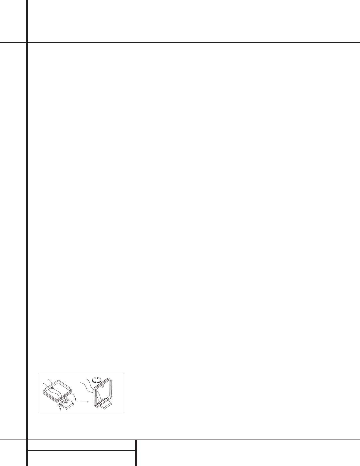
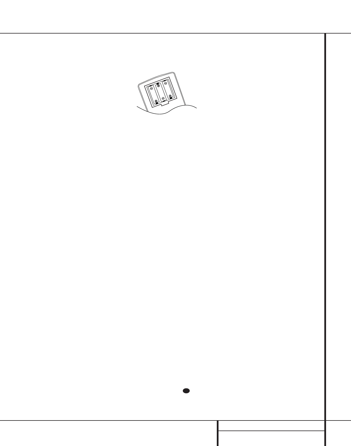
3. Install the three supplied AAA batteries in
the remote as shown. Be certain to follow
the (+) and (–) polarity indicators that are
on the bottom of the battery compartment.
4.Turn the AVR 110 on either by pressing the
System Power Control 2on the front
panel, or via the remote by pressing an Input
Selector efg on the remote.The
Power Indicator 3will turn green to con-
firm that the unit is on, and the Information
Display Ûand other indicators ˜ also
light up.
Speaker Configuration
These adjustments tell the AVR 110 which type
of speakers are in use.This is important as it
adjusts the settings that determine which
speakers receive low-frequency (bass) informa-
tion. For each of these settings use the
LARGE setting if the speakers for a
particular position are traditional full-range
loudspeakers that are capable of reproducing
sounds below 100Hz. Use the SMALL set-
ting for smaller, frequency-limited satellite
speakers that do not reproduce sounds below
100Hz. Note that when “small” speakers are
used, a subwoofer is required to reproduce
low-frequency sounds. Remember that the
“large” and “small” descriptions do not refer
to the actual physical size of the speakers, but
their ability to reproduce low-frequency
sounds. If you are in doubt as to which cat-
egory describes your speakers, consult the
specifications in the speakers’ owner’s manual,
or ask your dealer.
With the AVR 110 turned on, follow these steps
to configure the speakers:
1. Put the AVR 110 in the Dolby Pro Logic
mode by pressing the Surround Mode
Selector 7on the front panel or by
pressing the Surround Mode Selector
jon the remote, until PRO LOGIC
appears in the Main Information Display
Wand the PRO LOGIC indicator Flights.
2. Press the Speaker button ıon the
remote or front panel.The words FNT
SPEAKER will appear in the Main
Information Display W.
3. Press the Set button oÔ.
4. Press the
⁄
/
¤
buttons mq on the
remote or the Selector buttons 5on the
front panel until either LARGE or
SMALL appears, matching the type of
speakers you have at the left-front and
right-front positions, as described by the
definitions shown in preceding section.
When SMALL is selected, low-frequency
sounds will be sent to the subwoofer output
only. Note that if you choose this option,
and there is no subwoofer connected, you
will not hear any low-frequency sounds from
the front channels.
When LARGE is selected, a full-range out-
put will be sent to the front-left and front-
right outputs, and NO low-frequency signals
will be sent to the subwoofer output.
5.When you have completed your selection for
the front channel, press the Set button
oÔ, and then press the
⁄
/
¤
buttons
mq on the remote or the Selector
buttons 5on the front panel to change
the display to CEN SPEAKER.
6. Press the Set button oÔagain, and
use the
⁄
/
¤
buttons mq on the
remote, or the Selector buttons 5on the
front panel, to select the option that best
describes your system based on the speaker
definitions shown in preceding section.
When CEN SMALL is selected, low-fre-
quency center-channel sounds will be sent
to the subwoofer output only. Note that if
you choose this option and there is no sub-
woofer connected, you will not hear any
low-frequency sounds from the center-chan-
nel speaker.
When CEN LARGE is selected, a full-
range output will be sent to the center-
speaker output, and NO center channel sig-
nal will be sent to the subwoofer output.
When CEN NONE is selected, no signals
will be sent to the center-channel output.
The receiver will operate in a “phantom”
center-channel mode and center-channel
information will be sent to the left- and
right-front channel outputs.
31
18 SYSTEM CONFIGURATION
System Configuration
7.When you have completed your selection
for the center channel, press the Set
button oÔ, and then press the
‹
/
›
buttons non the remote or
the Selector buttons 5on the front
panel to change the display to SUR
SPEAKER.
8. Press the Set button tÔagain, and
then use the
⁄
/
¤
buttons mq on the
remote or the Selector buttons 5on the
front panel to select the option that best
describes your system based on the speaker
definitions shown in preceding section.
When SUR SMALL is selected, low-fre-
quency surround-channel sounds will be
sent to the subwoofer output only. Note
that if you choose this option and there is
no subwoofer connected, you will not hear
any low-frequency sounds from the sur-
round speaker.
When SUR LARGE is selected, a full-
range output will be sent to the surround-
channel outputs, and NO surround channel
signals will be sent to the subwoofer
output.
When SUR NONE is selected, surround-
sound information will be split between
the front-left and front-right outputs. Note
that for optimal performance when no sur-
round speakers are in use, the Dolby 3
Stereo mode should be used instead of
Dolby Pro Logic.
9.When you have completed your selection
for the surround channel, press the Set
button oÔ, and then press the
⁄
/
¤
buttons mq on the remote or the
Selector buttons 5on the front panel to
change the display to S-W SPEAKER.
10. Press the Set button oÔ, and then
press the
⁄
/
¤
buttons mq on the
remote or the Selector buttons 5on
the front panel to select the option that
best describes your system.
The choices available for the subwoofer
position will depend on the settings for the
other speakers, particularly the front left/right
positions.
If the front left/right speakers are set to
SMALL, the subwoofer will automatically be
set to SUB, which is the “on”position.
If the front left/right speakers are set to
LARGE, three options are available:
• If no subwoofer is connected to the
AVR 110, press the
⁄
/
¤
buttons mq
on the remote so that SUB NONE
appears in the Main Information
Display W.When this option is selected,
all bass information will be routed to the
front left/right “main” speakers.
• If a subwoofer is connected to the AVR 110,
you have the option to have the front
left/right “main” speakers reproduce bass
frequencies at all times, and have the sub-
woofer operate only when the AVR 210 is
being used with a digital source that con-
tains a dedicated Low-Frequency Effects, or
LFE, soundtrack.This allows you to use both
your main and subwoofer speakers to take
advantage of the special bass created for
certain movies. Press
⁄
/
¤
buttons mq
on the remote so that SUB (LFE)
appears in the Main Information
Display W.
• If a subwoofer is connected and you wish to
use it for bass reproduction in conjunction
with the main front left/right speakers,
regardless of the type of program source or
surround mode you are listening to, press
the
⁄
/
¤
buttons mq on the remote
so that SUB L/R+LFE appears in
the Main Information Display W.
When this option is selected, a “complete”
feed will be sent to the front left/right
“main” speakers, and the subwoofer will
receive the bass frequencies under frequen-
cy selected in the next option setting on this
menu, as described below.
11.When all speaker selections have been
made, press the Set button oÔto
return to normal operation.
Output Level Adjustment
Output level adjustment is a key part of the
configuration process for any surround-sound
product. It is particularly important for a Dolby
Digital receiver such as the AVR 110, as correct
outputs will ensure that you hear sound tracks
in their proper place with the proper direction-
ality and intensity.
IMPORTANT NOTE: Listeners are often con-
fused about the operation of the surround
channels.While some assume that sound
should always be coming from each speaker,
most of the time there will be little or no
sound in the surround channels.This is because
they are only used when a movie director or
sound mixer specifically places sound there to
create ambiance, a special effect or to continue
action from the front of the room to the rear.
When the output levels are properly set it is
normal for surround speakers to operate only
occasionally.Artificially increasing the volume
to the rear speakers may destroy the illusion
of an enveloping sound field that duplicates
the way you hear sound in a movie theater or
concert hall.
Before beginning the adjustment process make
certain that all speaker connections have been
properly made.The system volume should be
set to the level that you will use during a typi-
cal listening session. Finally,make certain that
the Balance Control * is set to the center
“12 o’clock” position.
To assist in making speaker configuration set-
tings, the icons in the Speaker/Channel
Input Indicators Ochange as the speaker
type is selected at each position.When only the
center icon box containing the abbreviation for
the speaker position is lit, the speaker is set for
“small.” When the inner box and the two outer
boxes with circles inside them are lit, the speak-
er is set for “large.” When no indicator appears
at a speaker location, that position is set for
“none” or “no” speaker.
For example, in the following figure, the left
front and right front speakers are set for
“large,” the center, left surround (LS) and right
surround (RS) speakers are set for small, and a
subwoofer is set, as shown by the box with the
abbreviation “LFE”, which stands for “low-fre-
quency effects.”
L
LS RS
RC
LFE
30

19 SYSTEM CONFIGURATION
To adjust and calibrate the output levels, follow
these steps. For accurate calibration,it is a
good idea to make these adjustments while
seated in your favorite listening position:
1. Put the AVR 110 in the Dolby Pro Logic
mode by pressing the Surround Mode
Selector 7on the front panel, or by
pressing the Surround Mode Selector
jon the remote, until PRO LOGIC
appears in the Main Information
Display W and the PRO LOGIC indicator
F lights up.
2. Press the Test button hon the remote.
The words T-T FL 0dB will appear
in the Main Information Display W and
the letters FL will flash once each second.
3.The test noise will immediately begin to
circulate in the speakers in a clockwise
rotation, pausing at each position for three
seconds.As the test noise rotates the
speaker position will be shown in the
Main Information Display W .
NOTE: This is a good time to verify that
the speakers have been properly connected.
As the test noise circulates, listen to make
certain that the sound comes from the
speaker position shown in the Main
Information Display. If the sound from
a speaker location does NOT match the
position indicated in the display, turn the
AVR 110 off using the Main Power
Switch 1and check the speaker wiring
to make certain that each speaker is con-
nected to the correct output terminal.
4.After checking for speaker placement, let
the test noise circulate, and listen to see
which channels sound louder than the
others. Using the front left (FL in the
display) speaker as a reference, press the
⁄
/
¤
buttons mq on the remote or
the Selector buttons 5on the front
panel on each channel to begin to bring
them to the same level. Note that when
one of the buttons is pushed, the test
noise circulation will pause on the channel
being adjusted to give you time to make
the adjustment.When you release the
button, the circulation will resume after
15 seconds.
5. Continue to adjust the individual speakers
until they all have the same volume. Note
that adjustments should be made with the
⁄
/
¤
buttons mq on the remote or
the Selector buttons 5on the front
panel only, NOT the main volume controls.
Then press the Set button oÔto mem-
orize the change. If you are using a sound
pressure (SPL) meter for precise level
adjustment, set the volume so that the
meter reads 75dB, C-Weighting Slow.
NOTE: The subwoofer output level is not
adjustable using the test tone.To change the
subwoofer level, follow the steps for Output
Level Trim Adjustment on page 26.
6.When you have adjusted the outputs so
that all channels have the same level, press
the Test button hon the remote to
complete the adjustment.
Delay Settings
Due the different distances between the front-
channel speakers and the listening position
compared to the surround speakers and the lis-
tening position, the amount of time it takes for
sound to reach your ears from the front or sur-
round speakers is different.You may compen-
sate for this difference through the use of the
delay settings to adjust the timing to tailor the
specific speaker placement and acoustic condi-
tions in your listening room or home theater.
The factory setting is appropriate for most
rooms, but some installations create an uncom-
mon distance between the front and surround
speakers that may cause the arrival of front-
channel sounds to become disconnected from
surround-channel sounds.
To resynchronize the front and surround chan-
nels, follow these steps:
1. Measure the distance from the listening/
viewing position to the front speakers.
2. Measure the distance from the listening/
viewing position to the surround speakers.
3. Subtract the distance to the surround speak-
ers from the distance to the front speakers.
a.When setting the delay time for the
Dolby Digital surround modes, the opti-
mal delay time is the result of that sub-
traction.For example, if the front speak-
ers are ten feet away and the surround
speakers are five feet away, the optimal
delay time is figured as 10–5=5.Thus, in
this example, the delay time for Dolby
Digital should be set at five milliseconds.
b.When setting the delay time for the
Pro Logic mode, take the result of the
subtraction and add 15 to obtain the
optimal delay time. For example,if the
front speakers are ten feet away and the
surround speakers are five feet away,
the optimal delay time is figured as
10–5+15=20.Thus, in this example, the
Pro Logic delay should be set at twenty
milliseconds.
NOTE: The Theater and Hall modes use a fixed,
nonadjustable delay time.
The Dolby Digital Mode also includes a sepa-
rate setting for the center-channel delay mode,
since the discrete nature of these signals makes
the location of the center-channel speaker more
critical.To calculate the delay for the center
channel, measure the distance from the pre-
ferred listening position in the center of the
room to both the center-channel speaker and
either the left or right speaker.
If the distances are equal, no further adjustment
is required and the center delay should be set to
zero. If the distance to the front speakers is
greater than the distance to the center speaker,
you may wish to reposition the speakers by
moving the front-left and front-right speakers
closer to the listening position or the center
speaker further away from the listening position.
If repositioning of the speakers is not possible,
adjust the center delay time, adding one mil-
lisecond of center-channel delay for every foot
closer to the listening position the center
speaker is than the front speakers. For example,
if the front-left and front-right speakers are
each 10 feet from the listening position and the
center-channel speaker is 8 feet away,the delay
is figured as 10–8=2, suggesting an optimal
center delay of 2 milliseconds.
System Configuration
20 SYSTEM CONFIGURATION
System Configuration
To set the delay times, follow these steps:
1. Put the AVR 110 in the Dolby Pro Logic
mode by pressing the Surround Mode
Selector 7on the front panel or by
pressing the Surround Mode Selector
jon the remote, until PRO LOGIC
appears in the Main Information Display
Wand the PRO LOGIC indicator F
lights up.
2. Press the Delay button Òon
the remote or front panel.The words
S DELAY TIME will appear in the
Main Information Display W.
3. Press the Set button oÔ.
4.Adjust the delay time by pressing the
⁄
/
¤
buttons mq on the remote or the
Selector buttons 5on the front panel
until the delay time figure calculated using
the formula entered above appears in the
display.
5. If only analog sources will be used, no
adjustment is needed for the center-channel
delay. In that case, press the Set button
oÔto enter the surround delay settings
into the AVR 110’s memory. However, if you
will be using digital sources and the calcu-
lations outlined above indicate that the
center-channel delay requires an adjust-
ment, continue with the following steps.
6. Before setting the center-channel delay
time, make certain that a digital source has
been selected. If a digital source is playing,
COAXIAL Eor OPTICAL Bwill appear
in the Information Display Û. If a digi-
tal source is already connected and play-
ing, press the Delay button Òand
then the
⁄
/
¤
buttons on the remote
mq or the front panel Selector
buttons 5until the words C DELAY
TIME appear in the Main Information
Display Ûand proceed to Step 10. If a
digital source is not playing, follow Steps 7
through 10.
7. Press the Set button oÔ.
8. Select the Dolby Digital mode either by
pressing the front panel Surround Mode
Selector 7or by pressing the Surround
Mode Selector jon the remote on the
remote until DOLBY DIG appears in the
Main Information Display W.
9. Press the Delay button Òon
the remote or front panel.The words
S DELAY TIME appear in the
Main Information Display W.
10.Press the
⁄
/
¤
buttons mq on the
remote once, so that C DELAY TIME
appears in the Main Information Display
Wor in the on-screen display.
11. Press the Set button oÔ.
12. Press the
⁄
/
¤
buttons mq on the
remote or the Selector buttons 5on
the front panel until the desired delay
time for the center channel appears in the
display.
13. Press the Set button oÔto enter the
setting into the AVR 110’s memory.
You have now completed the setup,adjustment
and calibration of the AVR 110.You are now
ready to enjoy the finest in music and home-
theater listening.
29
29
29
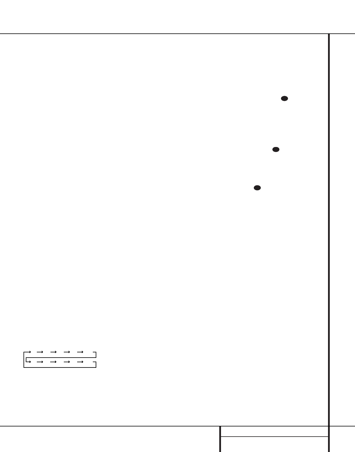
21 OPERATION
Operation
Basic Operation
Once you have completed the setup and
configuration of the AVR 110,it is simple to
operate and enjoy.The following instructions
will help you maximize the enjoyment of your
new receiver:
Turning the AVR 110 On or Off
• When using the AVR 110 for the first time, you
must press the Main Power Switch 1on the
front panel to turn the unit on.This places the
unit in a Standby mode, as indicated by the
amber color of the Power Indicator 3. Once
the unit is in Standby, you may begin a listening
session by pressing the System Power Control
2on the front panel or the AVR Selector
f. Note that the Power Indicator 3will
turn green.This will turn the unit on and return it
to the input source that was last used.The unit
may also be turned on from Standby by pressing
any of the Input Selector buttons on the
remote efg or the Input Source
Selector button !on the front panel.
NOTE: After pressing one of the Input Selector
buttons eg to turn the unit on, press the
AVR Selector fto set the remote control to
the AVR 110 functions.
To turn the unit off at the end of a listening
session, simply press the System Power
Control 2on the front panel or the Power
Off button don the remote. Power will be
shut off to any equipment plugged into the rear
panel Switched AC Outlets fland the
Power Indicator 3will turn amber.
When the remote is used to turn the unit “off”
it is actually placing the system in a Standby
mode, as indicated by the amber color of the
Power Indicator 3.
• To program the AVR 110 for automatic turn-
off, press the Sleep button ion the remote.
Each press of the button will increase the time
before shut down in the following sequence:
The sleep time will be displayed in the Preset
Number/Sleep Timer Indicator Pand it
will count down until the time has elapsed.
When the programmed sleep time has elapsed,
the unit will automatically turn off. Note that
the front panel display will dim to one half
brightness when the Sleep function is
programmed.To cancel the Sleep function,
press and hold the Sleep buttoniuntil
the information display returns to normal
brightness, the Sleep indicator numbers
disappear and the words SLEEP OFF
appear in the Main Information Display W.
When you will be away from home for an
extended period of time it is always a good
idea to completely turn the unit off with the
front panel Main Power Switch 1.
NOTE: All preset memories are lost if the unit is
left turned off by using the Main Power
Switch 1for more than two weeks.
Source Selection
• To select a source, press any of the Source
Selector buttons on the remote eg.
• The input source may also be changed by
pressing the front-panel Input Source
Selector button !. Each press of the button
will move the input selection through the list of
available inputs.
• As the input is changed, the AVR 110 will
automatically switch to the digital input (if
selected), surround mode,speaker configura-
tion, output levels,crossover frequency and
night mode status that were entered during the
configuration process for that source.
• The front-panel Video 4 Inputs %^ may
be used to connect a device such as a video
game or camcorder to your home entertain-
ment system on a temporary basis.
• As the input source is changed, the new input
name will appear momentarily as an on-screen
display in the lower third of the video display.
The input name will also appear in the Main
Information Display Wand a green LED will
light next to the selected input’s name in the
front panel Input Indicators .
• When an audio source is selected, the last
video input used remains routed to the Video
Outputs bf and Video Monitor Output
⁄.This permits simultaneous viewing and lis-
tening to different sources.
• When a Video source is selected,the video sig-
nal for that input will be routed to the Video
Monitor Output jack ⁄and will be viewable
on a TV monitor connected to the AVR 110.
Volume Control
• Adjust the volume to a comfortable level
using the front panel Volume Control Óor
remote Volume Up/Down buttons.
• When listening in the Stereo mode with the
surround circuits off, the Balance Control *
may be used to adjust the relative sound output
between the front left and front right speakers.
• To temporarily silence all speaker outputs
press the Mute button .This will interrupt
the output to all speakers and the headphone
jack, but it will not affect any recording or dub-
bing that may be in progress.When the system
is muted, the MUTE indicator Xwill light in
the Main Information Display Û. Press the
Mute button again to return to normal
operation.
• During a listening session you may wish to
adjust the Bass Control &and Treble
Control (to suit your listening tastes or
room acoustics.
• To set the output of the AVR 110 so that
the output is “flat,” with the tone controls de-
activated,press the Tone Mode button 6
button once or twice so that the words
Tone Out appear momentarily in the
Main Information Display W.To return the
tone controls to an active condition, press the
Tone Mode button 6once or twice so that
the words Tone In momentarily appear in
the Main Information Display W.
• For private listening, plug the 1/4" stereo
phone plug from a pair of stereo headphones
into the front panel Headphone jack 4. Note
that when the headphone’s plug is connected,
the word HEADPHONE will scroll once
across the Main Information Display W
and all speakers will be silenced.When the
headphone plug is removed, the audio feed to
the speakers will be restored.
35
35
33
90
min 80
min 70
min 60
min 50
min
40
min 30
min 20
min 10
min OFF

22 OPERATION
Operation
MODE FEATURES DELAY TIME RANGE
DOLBY DIGITAL Available only with digital input sources encoded with Dolby Digital data.It provides Center: 0 ms – 5 ms
up to five separate main audio channels and a special dedicated Low-Frequency Effects Initial Setting – 0 ms
channel. Surround: 0 ms –15 ms
Initial Setting – 0 ms
DTS Available only with digital input sources encoded with DTS data.Available on special Delay time not adjustable
DVD, LD and audio-only discs, DTS provides up to five separate main audio channels and
a special dedicated low-frequency channel.
DOLBY PRO LOGIC The standard mode for analog surround-sound decoding. It uses information encoded 15 ms – 30 ms
in a two-channel stereo recording to produce four distinct outputs: Left, Center, Right and Initial Setting = 15 ms
a Mono Surround channel. Use this mode for accurate reproduction of programs bearing
the Dolby Surround, DTS Stereo,UltraStereo or other “Surround” logos.Surround-encoded
programs include videocassette, DVD and LD movies,TV and cable programs, radio
programs and audio CDs. Dolby Pro Logic processing may also be used to provide a
pleasing surround effect with some stereophonic source material that does not carry
surround encoding.
LOGIC 7 C Logic 7 is an advanced mode that extracts the maximum surround information from either Delay time not adjustable
LOGIC 7 M surround-encoded programs or conventional stereo material.The Logic 7 C or Cinema mode
should be used with any source that contains Dolby Surround or similar matrix encoding.
Logic 7 C delivers increased center-channel intelligibility, and more accurate placement of sounds
with fades and pans that are much smoother and more realistic than with other decoding
techniques.The Logic 7 M or Music mode should be used with analog or PCM stereo sources.
Logic 7 M enhances the listening experience by presenting a wider front soundstage and greater
rear ambience. Both Logic 7 modes also direct low-frequency information to the subwoofer
(if installed and configured) to deliver maximum bass impact.
DOLBY 3 STEREO Uses the information contained in a surround-encoded or two-channel stereo program to No surround channels
create center-channel information. In addition,the information that is normally sent to the
rear-channel surround speakers is carefully mixed in with the front-left and front-right
channels for increased realism. Use this mode when you have a center-channel speaker
but no surround speakers.
THEATER Surround processing uses matrix surround decoding to simulate a standard movie or Delay time not adjustable
stage theater.
HALL 1 The Hall mode offers a matrix surround choice that simulates a medium-sized chamber hall. Delay time not adjustable
VMAx Near When only the two front-channel loudspeakers are used, Harman’s patented VMAx mode No surround channels
VMAx Far delivers a three-dimensional sound space with the illusion of “phantom speakers” at the
center and surround positions.The VMAx N, or “Near Field” mode should be selected when
your listening position is less than five feet from the speakers.The VMAx F, or “Far Field” mode
should be selected when your listening position is greater than five feet from the speakers.
5-Channel Stereo This mode takes advantage of multiple speakers to place a stereo signal at both the front and No delay is available for
back of a room. Ideal for playing music in situations such as a party,it places the same signal this mode
at the front-left and surround-left, and front-right and surround-right speakers.The center
channel is fed a summed mono mix of the in-phase material of the left and right channels.
SURROUND This mode turns off all surround processing and presents the pure left- and right- No surround channels
OFF (STEREO) channel presentation of two-channel stereo programs.
Surround Mode Chart

23 OPERATION
Operation
Surround Mode Selection
One of the most important features of the
AVR 110 is its ability to reproduce a full
multichannel surround-sound field from digital
sources, analog matrix surround-encoded
programs and standard stereo programs. In all,
a total of twelve listening modes are available
on the AVR 110.
Selection of a surround mode is based on per-
sonal taste, as well as the type of program
source material being used. For example, motion
pictures or TV programs bearing the logo of one
of the major surround-encoding processes, such
as Dolby Surround, DTS Stereo or UltraStereo®
may be played in either the Dolby Digital, Dolby
Pro Logic or Logic 7 Cinema surround modes
depending on the source material.
NOTE: Once a program has been encoded with
matrix surround information, it retains the sur-
round information as long as the program is
broadcast in stereo.Thus, movies with surround
sound may be decoded via any of the analog
surround modes such as Pro Logic or Logic 7,
when they are broadcast via conventional TV sta-
tions, cable, pay TV and satellite transmission. In
addition, a growing number of made-for-televi-
sion programs, sports broadcasts, radio dramas
and music CDs are also recorded in surround
sound.You may view a list of these programs
at the Dolby Laboratories Web site at
www.dolby.com.
Even when a program is not listed as carrying
intentional surround information, you may find
that the Pro Logic, Logic 7,VMAx and the Hall or
Theater modes often deliver enveloping surround
presentations through the use of the natural
information present in all stereo recordings.
However, for stereo,but not surround programs,
we suggest that you experiment with the
other modes.
Surround modes are selected using either the
front panel controls or the remote.To select a
surround mode from the front panel, press the
Surround Mode Selector 7to scroll up or
down through the list of available modes.To
select a surround mode using the remote, press
the Surround Mode Selectorjand then
press the
⁄
/
¤
buttons mq to change the
mode.As you press the buttons, the Surround
mode name will appear in the Main
Information Display W, and an individual
mode indicator will also light up CDFHI
JKL.As the surround modes change, a
green LED will light next to the current mode in
the Surround Mode Indicators list ˜on
the front panel.
Note that the Dolby Digital and DTS modes may
only be selected when a digital input is in use.
In addition, when a digital source is present,
the AVR 110 will automatically select and
switch to the correct mode (Dolby Digital or
DTS), regardless of the mode that has been pre-
viously selected. For more information on select-
ing digital sources, see the following section of
this manual.
To listen to a program in traditional two-channel
stereo, using the front-left and front-right
speakers only (plus the subwoofer if installed
and configured), follow the instructions shown
above for using the remote until SURR OFF
appears in the Main Information Display W.
Digital Audio Playback
Digital audio is a major advancement over older
systems such as Dolby Pro Logic. It delivers five
discrete channels: left-front, center, right-front,
left-surround and right-surround. Each channel
reproduces full frequency range (20Hz to 20kHz)
and offers dramatically improved dynamic range
and significant improvements to signal-to-noise
ratios. In addition,digital systems have the capa-
bility to deliver an additional channel that is
specifically devoted to low-frequency information.
This is the “.1”channel referred to when you see
these systems described as “5.1”.The bass chan-
nel is separate from the other channels, but since
it is intentionally bandwidth-limited, sound
designers have given it that unique designation.
Dolby Digital
Dolby Digital (originally known as AC-3®) is
a standard part of DVD, and is available on
specially encoded LD discs and satellite broad-
casts and is a part of the new high-definition tel-
evision (HDTV) system.
Note that an optional, external RF demodulator
is required to use the AVR 110 to listen to the
Dolby Digital soundtracks available on laser
discs. Connect the RF output of the LD player to
the demodulator and then connect the digital
output of the demodulator to the Optical or
Coaxial Inputs gh#$ of the AVR 110.
No demodulator is required for use with DVD
players or DTS-encoded laser discs.
DTS
DTS is another digital audio system that is
capable of delivering 5.1 audio.Although both
DTS and Dolby Digital are digital, they use dif-
ferent methods of encoding the signals, and
thus they require different decoding circuits to
convert the digital signals back to analog.
DTS-encoded sound tracks are available on
select DVD and LD discs, as well as on special
audio-only DTS discs.You may use any LD or
CD player equipped with a digital output to
play DTS-encoded discs with the AVR 110.All
that is required is to connect the player’s output
to either the Optical or Coaxial Input on the
rear panel gh or front panel #$.
In order to listen to DVDs encoded with DTS
sound tracks, the DVD player must be compati-
ble with the DTS signal as indicated by a DTS
logo on the player’s front panel. Note that early
DVD players may not be able to play DTS-
encoded DVDs.This does not indicate a prob-
lem with the AVR 110, as some players cannot
pass the DTS signal through to the digital out-
puts. If you are in doubt as to the capability of
your DVD player to handle DTS discs, consult
the player’s owner’s manual.
Selecting a Digital Source
To utilize either digital mode you must have
properly connected a digital source to the
AVR 110. Connect the digital outputs from DVD
players, HDTV receivers, satellite systems or CD
players to the Optical or Coaxial Inputs
gh#$. In order to provide a backup sig-
nal and a source for analog stereo recording,
the analog outputs provided on digital source
equipment should also be connected to their
appropriate inputs on the AVR 110 rear panel
(e.g., connect the analog stereo audio output
from a DVD to the DVD Audio inputs §on
the rear panel when you connect the source’s
digital outputs).
When playing a digital source such as DVD, first
select the input using the remote or front panel
controls as outlined in this manual. Next, select
the digital source by pressing the Digital
Input Selector button pÚ and then using
the ⁄/¤buttons mq on the remote or the
Selector buttons5on the front panel to
choose any of the OPTICAL or COAXIAL
inputs, as they appear in the Main
Information Display W, or Source
Indicators BE.When the digital source is

24 OPERATION
Operation
playing, the AVR 110 will automatically detect
whether it is a multichannel Dolby Digital, DTS
source, MP3 or a conventional PCM signal,
which is the standard output from CD players.
A Bitstream Indicator Awill light in the
Main Information Display Ûto confirm
that the digital signal is Dolby Digital, DTS
or PCM.
Digital Status Indicators
When a digital source is playing, the AVR 110
senses the type of bitstream data that is pres-
ent. Using this information, the correct sur-
round mode will automatically be selected. For
example, DTS bitstreams will cause the unit to
switch to DTS decoding, and Dolby Digital bit-
streams will enable Dolby Digital decoding.
When the unit senses PCM data from CDs and
LDs, it will allow the appropriate surround
sources to be selected manually. Since the
range of available surround modes is depend-
ent on the type of digital data that is present,
the AVR 110 uses a variety of indicators to
let you know what type of signal is present.
This will help you to understand the choice
of modes.
When a digital source is playing, a Bitstream
Indicator Awill light to show which type of
signal is playing:
DOLBY D:When the DOLBY D indicator
lights, a Dolby Digital bitstream is being
received. Depending on the settings on the
source player and specific surround information
and number of channels on the disc, a number
of surround modes are possible. For discs with
full 5.1 audio, only the Dolby Digital and VMAx
modes are available.When the Dolby Digital
signal is only two-channel, you may also select
from the Logic 7 Cinema/Music, Hall,Theater,
Dolby Pro Logic or Dolby 3 Stereo modes.
DTS:When the DTS indicator lights, a DTS
bitstream is being received.When the unit
senses this type of data, only the DTS mode
may be used.
PCM:When the PCM indicator lights, a stan-
dard Pulse Code Modulation, or PCM, signal is
being received.This is the type of digital audio
used by conventional compact disc and laser
disc recordings.When a PCM bitstream is pres-
ent, all modes except Dolby Digital and DTS are
available.
MP3:When the MP3 indicator lights, a com-
patible MPEG 1/Layer 3 digital signal is being
received.This is the popular audio format used
by many computer programs for recording com-
pressed audio files.When an MP3 bitstream is
present, the sound will automatically be played
in the stereo (surround off) mode.The surround
modes are not available during MP3 playback.
In addition to the bitstream indicators, the
AVR 110 features a set of unique channel-input
indicators that tell you how many channels of
digital information are being received and/or
whether the digital signal is interrupted.
These indicators are the L/C/R/LS/RS/LFE letters
that are inside the center boxes of the
Speaker/Channel Input Indicators Oin
the front panel Main Information Display
Û.When a standard analog signal is in use,
only the “L” and “R” indicators will light,as
analog signals have only left and right chan-
nels, respectively.
Digital signals, however, may have two, five or
six separate channels, depending on the pro-
gram material,the method of transmission and
the way in which it was encoded.When a digi-
tal signal is playing, the letters in these indica-
tors will light in response to the specific signal
being received. It is important to note that
although Dolby Digital, for example,is referred
to as a “5.1” system, not all Dolby Digital DVDs
or programs are encoded for 5.1.Thus, it is
sometimes normal for a DVD with a Dolby
Digital soundtrack to trigger only the “L” and
“R” indicators.
NOTE: Many DVD discs are recorded with both
“5.1” and “2.0”versions of the same sound-
track.When playing a DVD,always be certain to
check the type of material on the disc. Most
discs show this information in the form of a
listing or icon on the back of the disc jacket.
When a disc does offer multiple soundtrack
choices you may have to make some adjust-
ments to your DVD player (usually with the
“Audio Select” button or in a menu screen
on the disc) to send a full 5.1 feed to the
AVR 110. It is also possible for the type of sig-
nal feed to change during the course of a DVD
playback. In some cases the previews of special
material will only be recorded in 2.0 audio,
while the main feature is available in 5.1 audio.
As long as your DVD player is set for 6-channel
output, the AVR 110 will automatically sense
changes to the bitstream and channel count
and reflect them in these indicators.
The letters used by the Speaker/Channel
Input Indicators Oalso flash to indicate
when a bitstream has been interrupted.This
will happen when a digital input source is
selected before the playback starts, or when a
digital source such as a DVD is paused.The
flashing indicators remind you that the play-
back has stopped due to the absence of a
digital signal and not through any fault of the
AVR 110.This is normal, and the digital play-
back will resume once the playback is started
again.
Night Mode
A special feature of Dolby Digital is the Night
mode, which enables AC-3 input sources to be
played back with full digital intelligibilty while
reducing the minimum peak level by 1/4to 1/3.
This prevents abruptly loud transitions from dis-
turbing others, without reducing the impact of
the digital source.The Night mode is available
only when Dolby Digital signals with special
data are being played.
The Night mode may be engaged when a Dolby
Digital DVD is playing by pressing the Night
Mode button kon the remote. Next, press
the ⁄/¤buttons mq to select either the
middle range or full compression versions of the
Night mode.To turn the Night mode off, press
the ⁄/¤buttons mq until the message
in the lower third of the video display and the
Main Information Display Wreads
D-Range Off.When the Night mode is
active, the Night Mode Indicator Nwill
also light.
IMPORTANT NOTES ON
DIGITAL PLAYBACK:
1.When the digital playback source is stopped,
or in a Pause, Fast Forward or Chapter Search
mode, the digital audio data will momentarily
stop, and the channel position letters inside the
Speaker/Channel Input Indicators Owill
flash.This is normal and does not indicate a
problem with either the AVR 110 or the source
machine.The AVR 110 will return to digital
playback as soon as the data is available and
when the machine is in a standard play mode.
2.Although the AVR 110 will decode virtually all
DVD movies, CDs and HDTV sources, it is possible
that some future digital sources may not be com-
patible with the AVR 110.

25 OPERATION
Operation
3. Note that not all digitally encoded programs
contain full 5.1-channel audio. Consult the pro-
gram guide that accompanies the DVD or laser
disc to determine which type of audio has been
recorded on the disc.The AVR 110 will auto-
matically sense the type of digital surround
encoding used and adjust to accommodate it.
4.When a digital source is playing, you may not
be able to select some of the analog surround
modes such as Dolby Pro Logic, Dolby 3, Stereo,
Hall,Theater or Logic 7.
5.When a Dolby Digital or DTS source is play-
ing, it is not possible to make an analog record-
ing using the Tape ™and Video 1 or Video
2 Record Outputs ∞bfi. However, the
digital signals will be passed through to the
Digital Audio Outputs ª.
PCM Audio Playback
PCM (Pulse Code Modulation) is the non-
compressed digital audio system used for
compact discs and laser discs.The digital circuits
in the AVR 110 are capable of high-quality
digital-to-analog decoding, and they may be
connected directly to the digital audio output
of your CD or LD player.
Connections may be made to either the rear
panel Optical or Coaxial Inputs gh or the
front panel Digital Inputs #$.
To listen to a PCM digital source,first select the
input for the desired source (e.g., CD).Next press
the Digital Select button Úp and then use
the
⁄
/
¤
buttons mq on the remote,or the
Selector buttons5on the front panel, until
the desired choice appears in the Main
Information Display W.
When a PCM source is playing, the PCM indi-
cator Awill light. During PCM playback you
may select any surround mode except Dolby
Digital or DTS.
Playback from PCM sources may also benefit
from the Logic 7 Mode.When playing back a
surround-encoded PCM source, such as an LD
or surround-encoded CD, use the Logic 7 C or
Cinema mode.When playing true stereo
recordings, use the Logic 7 M or Music mode
for a wider soundstage and increased rear-
channel ambience.
MP3 Audio Playback
The AVR 110 is one of the first A/V receivers to
provide on-board decoding for the MP3 audio
format used by computers and portable audio
devices. In addition, some new CD players are
capable of playing back optical discs that are
recorded with MP3, rather than standard CD
audio information. By offering MP3 decoding,
the AVR 110 is able to deliver more precise
conversion of the digital signals to an analog
output, along with the benefits of listening to
the MP3 audio through the AVR 110’s high
current amplifier and the speakers from your
surround system, rather than the smaller
speakers and low-powered amplifiers typically
used with computers.
To take advantage of the AVR 110’s MP3 capa-
bilities, simply connect the PCM output of a
computer’s sound card or the PCM output of a
portable digital audio device to either the rear
panel Digital Inputs gh or the front panel
Digital Inputs #$.As soon as the digital
signal is available, the MP3 Bitstream
Indicator Awill light, and the audio will
begin playing.
NOTES:
• The AVR 110 is only capable of playing sig-
nals in the MP3 (MPEG 1/Layer 3) format. It
is not compatible with other computer audio
codecs.
• The digital audio input signal may be either
optical or coaxial, but the signal must be in
the PCM format. Direct connection of USB or
serial data outputs is not possible, even
though the signals are in the MP3 format. If
you have any questions about the data out-
put format from your computer or a sound
card, check with the device’s owner’s manual
or contact the manufacturer’s technical sup-
port area.
Tuner Operation
The AVR 110’s tuner is capable of tuning AM,
FM and FM Stereo broadcast stations. Stations
may be tuned manually, or they may be stored
as favorite station presets and recalled from a
30-position memory.
Station Selection
1. Press the AM/FM Tuner Select button g
on the remote to select the tuner as an input.
The tuner may be selected from the front panel
by either pressing the Input Source Selector
!until the tuner is active or by pressing the
Tuner Band Selector 9at any time.
2. Press the AM/FM Tuner Select button g
or Tuner Band Selector 9again to switch
between AM and FM so that the desired
frequency band is selected.
3. Press the FM Mode button @sto select
manual or automatic tuning.
When the AUTO indicator Vis illuminated in
the Main Information Display Wthe tuner
will stop only at those stations that have a
strong enough signal to be received with
acceptable quality.
When the AUTO indicator Vis not illumi-
nated, the tuner is in a manual mode and
will stop at each frequency increment in the
selected band.
4.To select stations, press the Tuning
Selector button 8u.When the AUTO
indicator Vis illuminated, press the button
for two seconds and then release to cause the
tuner to search for the next highest- or lowest-
frequency station that has an acceptable signal.
When tuning FM stations in the Auto mode, the
tuner will select only stereo stations.To tune to
the next station, press the button again. If the
STEREO indicator Tis not illuminated, tap
the Tuning Selector button 8uto
advance one frequency increment at a time, or
press and hold it to locate a specific station.
When the TUNED indicator Ulights, the sta-
tion is properly tuned and should be heard with
clarity.
5. Stations may also be tuned directly by press-
ing the Direct button t, and then pressing
the Numeric Keys rthat correspond to the
station’s frequency.The desired station will
automatically be tuned. If you press an incor-
rect button while entering a direct frequency,
press the Clear button `to start over.
NOTE: When the FM reception of a station is
weak, audio quality will be increased by
switching to Mono mode by pressing the
FM Mode button @suntil the STEREO
indicator Tgoes out.
26 OPERATION
Operation
Preset Tuning
Using the remote, up to 30 stations may be
stored in the AVR 110’s memory for easy recall
using the front panel controls or the remote.
To enter a station into the memory,first tune
the station using the steps outlined above.
Then:
1. Press the Memory button on the
remote. Note that the MEMORY indicator S
will be illuminated and flash in the Main
Information Display Û.
2.Within five seconds, press the Numeric
Keys rcorresponding to the location where
you wish to store this station’s frequency. Once
entered, the preset number will appear in the
Preset Number/Sleep Timer display iP.
3. Repeat the process after tuning any
additional stations to be preset.
Recalling Preset Stations
• To manually select a station previously
entered in the preset memory, press the
Numeric Keys rthat correspond to the
desired station’s memory location.
• To manually tune through the list of stored
preset stations one by one, press the Preset
Stations Selector buttons )z on the
front panel or remote.
Tape Recording
In normal operation,the audio or video source
selected for listening through the AVR 110 is
sent to the record outputs.This means that any
program you are watching or listening to may
be recorded simply by placing machines con-
nected to the outputs for Tape Outputs ™or
Video 1 or 2 Outputs ∞bfi in the
record mode.
When a digital audio recorder is connected to
the Digital Audio Outputs ª, you are able
to record the digital signal using a CD-R,
MiniDisc or other digital recording system.
NOTES:
• The digital outputs are active only when a
digital signal is present, and they do not
convert an analog input to a digital signal,
or change the format of the digital signal.
In addition, the digital recorder must be
compatible with the output signal. For
example, the PCM digital input from a CD
player may be recorded on a CD-R or
MiniDisc, but Dolby Digital or DTS signals
may not.
• Please make certain that you are aware of
any copyright restrictions on any material you
copy. Unauthorized duplication of copyrighted
materials is prohibited by federal law.
Output Level Trim Adjustment
Normal output level adjustment for the
AVR 110 is established using the test tone,as
outlined on pages 22 and 23. In some cases,
however, it may be desirable to adjust the out-
put levels using program material such as a test
disc, or a selection you are familiar with.
Additionally, the output level for the subwoofer
can only be adjusted using this procedure.
To adjust the output levels using program
material, first set the reference volume for the
front-left and front-right channels using the
Volume Control Ó.
Once the reference level has been set, press
the Channel Select button lÙand note
that FRONT L LEV will appear in the
Main Information Display W.To change
the level, first press the Set button oÔ ,
and then use the Selector buttons 5or the
⁄
/
¤
buttons mq to raise or lower the
level. DO NOT use the volume control, as this
will alter the reference setting.
Once the change has been made, press the Set
button oÔ and then press the Selector
buttons 5or the ⁄/¤buttons mq to
select the next output channel location that you
wish to adjust.To adjust the subwoofer level,
press the Selector buttons 5or the ⁄/¤
buttons mq until SW LEV appears in the
Main Information Display W.
Press the Set button oÔ when the name of
the desired channel appears in the Main
Information Display Wfollow the instruc-
tions shown earlier to adjust the level.
Repeat the procedure as needed until all chan-
nels requiring adjustment have been set.When
all adjustments have been made and no further
adjustments are made for five seconds, the
AVR 110 will return to normal operation.
NOTE: The output levels may be separately
trimmed for each digital and analog surround
mode. If you wish to have different trim levels for
a specific mode, select that mode and then follow
the instructions in the steps shown earlier.
Display Brightness
The AVR 110’s Main Information Display
Ûis set at a default brightness level that is
sufficient for viewing in a normally lit room.
However, in some home-theater installations,
you may wish to occasionally lower the bright-
ness of the display, or turn it off completely.
To change the display brightness, press and
hold the Set button Ôon the front for three
seconds until the message in the Main
Information Display Wreads VFD
FULL.Within five seconds, press the front
panel Selector buttons 5until the desired
brightness display level is shown.At that point,
press the Set button Ôagain to enter the
setting.
When FULL appears in the Main
Information Display W,the display is at its
normal brightness.When HALF appears, the
display is at half the normal brightness level.
When OFF appears, all of the indicators in the
Main Information Display Ûwill go dark.
Note, however, that the green LEDs for the
Input Indicators and the Surround
Mode Indicators ˜, as well as for the
Power Indicator 3, will always remain lit to
remind you that the unit is turned on.
Once the desired brightness level is selected, it
will remain in effect until it is changed again or
until the unit is turned off.
Memory Backup
This product is equipped with a memory backup
system that preserves the system configuration
information and tuner presets if the unit is acci-
dentally unplugged or subjected to a power
outage.This memory will last for approximately
two weeks, after which time all information
must be reentered.
33
28
27 PROGRAMMING THE REMOTE
Programming the Remote
The AVR 110 is equipped with a powerful
remote control that will control not only the
receiver’s functions, but also most popular
brands of audio and video equipment,including
CD players, cassette decks,TV sets,cable boxes,
VCRs, satellite receivers and other home-theater
equipment. Once the AVR 110’s remote is pro-
grammed with the codes for the products you
own, it is possible to eliminate most other
remotes and replace them with the convenience
of a single, universal remote control.
Programming the Remote
As shipped from the factory, the remote is fully
programmed for all AVR 110 functions, as well
as those of most Harman Kardon CD changers,
DVD players, CD players and cassette decks.In
addition, by following one of the methods below,
you may program the remote to operate a wide
range of devices from other manufacturers.
Direct Code Entry
This method is the easiest way to program your
remote to work with different products.
1. Use the tables in the following pages to
determine the three-digit code or codes that
match both the product type (e.g.,VCR,TV)
and the specific brand name. If there is
more than one number for a brand,make
note of the different choices.
2.Turn on the unit you wish to program into
the AVR 110 remote.
3. Press and hold both the Input Selector
efor the product you wish to control
(e.g.,VCR,TV) and the Mute button
at the same time.When the Program
Indicator cturns amber and begins
flashing, release the buttons.It is important
that you begin the next step within 20
seconds.
4. Point the AVR 110’s remote towards the unit
to be programmed,and enter the first three-
digit code number using the Numeric Keys
r. If the unit turns off, the correct code has
been entered. Press the Input Selector e
again, and note that the red light will flash
three times before going dark to confirm the
entry.
5. If the device to be programmed in does NOT
turn off, continue to enter three-digit code
numbers until the equipment turns off.At
this point, the correct code has been
entered. Press the Input Selector e
again and note that the red light under the
Input Selector will flash three times
before going dark to confirm the entry.
6.Try all of the functions on the remote to
make certain that the product operates
properly. Keep in mind that many manufac-
turers use a number of different combina-
tions of codes, so it is a good idea to make
certain that not only the power control, but
the volume, channel and transport controls
work as they should. If functions do not
work properly, you may need to use a differ-
ent remote code.
7. If a code cannot be entered to turn the
unit off, if the code for your product does
not appear in the tables in this manual, or
if not all functions operate properly, try
programming the remote with the Auto
Search Method.
Auto Search Method
If the unit you wish to include in the AVR 110’s
remote is not listed in the code tables in this
manual or if the code does not seem to operate
properly, you may wish to program the correct
code using the Auto Search method that follows:
1.Turn on the unit that you wish to include in
the AVR 110 remote.
2. Press the Input Selector efor the type
of product to be entered (e.g.,VCR,TV) and
the Mute button at the same time.
Hold both buttons until the red light under
the Input Selector estays lit.Note that
the next step must take place while the red
light is on, and it must begin within 20 sec-
onds after the light appears.
3. Point the AVR 110 remote towards the
unit to be programmed,and press either
⁄
or
¤
button mq. Each press will send
out a series of codes from the remote’s
built-in database.When the unit being pro-
grammed turns off, release the
⁄
or
¤
but-
ton mq, as that is your indication that
the correct code is in use.
4. Press the Input Selector e,and note
that the red light under the Input Selector
will flash three times before going dark to
confirm the entry.
5.Try all of the functions on the remote to
make certain that the product operates.
Keep in mind that many manufacturers use
a number of different combinations of
codes, and it is a good idea to make certain
that not only the power control works, but
also that the volume, channel and transport
controls, as appropriate. If all functions do
not work properly, you may need to Auto-
Search for a different code, or enter a code
via the Direct Code Entry method.
Code Readout
When the code has been entered using the Auto
Search method, it is always a good idea to find
out the exact code so that it may be easily reen-
tered if necessary.You may also read the codes
to verify which device has been programmed to
a specific Control Selector button.
1. Press and hold both the Input Selector
efor the device you wish to find the
code for and the Mute button at the
same time. Note that the Program
Indicator cwill initally turn amber.
Release the buttons and begin the next
step within 20 seconds.
2.Press the Set button o.The Program
Indicator cwill then blink green in a
sequence that corresponds to the three-digit
code, with a one-second pause between each
digit. Count the number of blinks between
each pause to determine the digit of the
code. One blink is the number 1,two blinks is
the number 2, and so forth.Ten blinks are
used to indicate a “0.”
Example: One blink, followed by a one-second
pause, followed by six blinks, followed by a
one-second pause, followed by ten blinks indi-
cates that the code has been set to 160.
For future reference enter the Setup Codes for
the equipment in your system here:
DVD ____________ CD ________________
VID1/VCR ________ VID2/TV __________
VID3/CBL/SAT ______________________
VID4 ____________ TAPE ____________
35
35
35
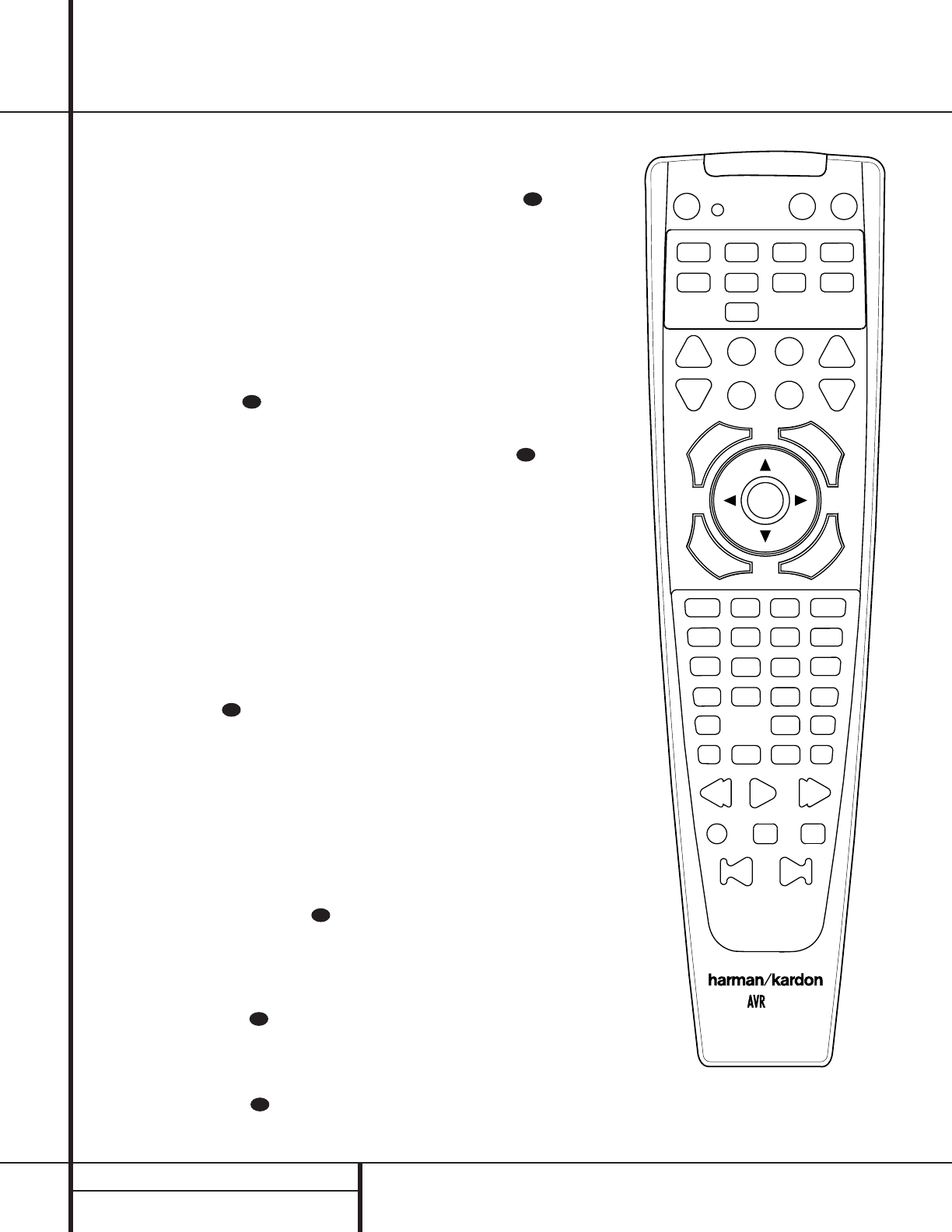
28 PROGRAMMING THE REMOTE
Programming the Remote
Macro Programming
Macros enable you to easily repeat frequently
used combinations of commands with the press
of a single button on the AVR 110’s remote con-
trol. Once programmed, a macro will send out
up to 19 different remote codes in a predeter-
mined sequential order enabling you to auto-
mate the process of turning on your system,
changing devices, or other common tasks.The
AVR 110’s remote can store up to five separate
macro command sequences: one that is
associated with the Power On button a, and
four more that are accessed by pressing the
Macro buttons v.
1. Press the Mute button and the
Macro button vto be programmed or
the Power On button aat the same
time. Note that an Input Selector ewill
light red, and the Program Indicator c
will flash amber.
2. Enter the steps for the macro sequence by
pressing the button for the actual command
step.Although the macro may contain up to
19 steps, each button press, including those
used to change devices, counts as a step.
The Program Indicator cwill flash
green to confirm each button press as you
enter commands.
NOTE: While entering commands for Power
On/Off of any device during a macro sequence,
press the Mute button . DO NOT press the
actual Power button.
3.When all the steps have been entered,
press the Sleep button ito enter the
commands. The red light under the Input
Selectors ef will blink and then
turn off.
Example: To program the Macro 1 button
so that it turns on the AVR 110,TV and a
Cable Box,follow these steps:
• Press the Macro 1 vand Mute
buttons at the same time and then release
them.
• Note that the Program Indicator c
will flash amber.
• Press the AVR Selector f.
• Press the Mute button to store the
AVR 110’s power on command.
• Press the VID 2 Input Selector button
eto indicate the next command is for
“TV Power On.”
• Press the Mute button to store the
TV Power On Command.
• Press the VID 3 Input Selector button
eto indicate the next command is for
“Cable Power On.”
• Press the Mute button to store the
Cable Power On command.
• Press the Sleep/Channel Up button i
to complete the process and store the
macro sequence.
After following these steps, each time you
press the Macro 1 button v, the remote
will send the Power On/Off command.
Erasing Macro Commands
To remove the commands that have been pro-
grammed into one of the Macro buttons, follow
these steps:
1. Press the Mute button and the
Macro button vthat contains the com-
mands you wish to erase.
2. Note that the Program Indicator cwill
flash amber, and the LED under the AVR
Selector fwill turn red.
3.Within ten seconds, press the Surround
Mode Selector/Channel Down
button j.
4.The red LED under the AVR Selector f
will go out, and the Program Indicator
cwill turn green and flash three times
before it goes out.
5.When the Program Indicator cgoes
out, the Macro has been erased.
Programmed Device Functions
Once the AVR 110’s remote has been pro-
grammed for the codes of other devices, press
the appropriate Input Selector eto change
the remote from controlling theAVR 110 to con-
trolling the additional product.When you press
any one of the selectors, it will briefly flash in red
to indicate that you have changed the device
being controlled.
When operating a device other than the
AVR 110, the controls may not correspond
exactly to the function printed on the remote
or button. Some commands,such as the volume
control, are the same as they are with the
AVR 110. Other buttons will change their
function so that they correspond to a secondary
label on the remote. For example,the Sleep
and Surround mode selector buttons also func-
tion as the Channel Up and Channel Down
35
35
35
35
35
35
35
1
4567
8910 11
13
17
21 23
24 25 26
28 27 29
30 31 32 33
34 35 36 37
38 39 40 41
42 43 44 45
46 47 48
49 50 51 52
53 54 55
56 57 58
59 60
22
14 15 16
20
19
18
12
23
110
29 PROGRAMMING THE REMOTE
Programming the Remote
buttons when operating most TV sets,VCRs or
cable boxes.The Channel Up/Down indication is
printed directly on the remote. For many stan-
dard CD players, cassette decks,VCRs and DVD
functions, the standard function icons are
printed on top of the buttons.
For some products, however, the function of a
particular button does not follow the command
printed on the remote. In order to see which
function a button controls, consult the Function
List tables printed on pages 31 and 32.To use
those tables, first check the type of device being
controlled (e.g.,TV,VCR). Next, look at the
remote control diagram pictured at the left.
Note that each button has a number on it.
To find out what function a particular button
has for a specific device, find the button num-
ber on the Function List and then look in the
column for the device you are controlling. For
example, button number 50 is the Macro 2
button for the AVR 110, but it is the “Favorite”
button for many cable television boxes and
satellite receivers. Button number 29 is the
Delay button for the AVR 110, but the + Time
button for CD players.
Note that the numbers used to describe the
button functions at the left for the purposes of
describing how a button operates are a differ-
ent set of numbers than those used in the rest
of this manual to describe the button functions
for the AVR 110.
Notes on Using the AVR 110 Remote With
Other Devices.
• Manufacturers may use different code sets for
the same product category. For that reason, it
is important that you check to see if the code
set you have entered operates as many con-
trols as possible. If it appears that only a few
functions operate, check to see if another
code set will work with more buttons.
• When a button is pressed on the AVR 110
remote, the red light under the Input
Selector efor the product being operat-
ed should flash briefly. If the Device Control
Selector flashes for some but not all buttons
for a particular product, it does NOT indicate
a problem with the remote but rather that
no function is programmed for the button
being pushed.
Volume Punch-Through
The AVR 110’s remote may be programmed to
operate the Volume Control and Mute
functions of either the TV or the AVR 110
in conjunction with any of the devices con-
trolled by the remote. For example,since the
AVR 110 will likely be used as the sound sys-
tem for TV viewing, you may wish to have the
AVR 110’s volume activated,although the
remote is set to run the TV. Either the AVR 110
or TV volume control may be associated with
any of the remote’s devices.To program the
remote for Volume Punch-Through, follow
these steps:
1. Press the Input Selector efor the unit
you wish to have associated with the volume
control and the Mute button at the
same time until the red light appears under
the Input Selector eand note that the
Program Indicator cwill flash amber.
2. Press the Volume Up button and note
that the Program Indicator cwill stop
flashing and stay amber.
3. Press either the AVR Selector for the
Input Selector e,depending on which
system’s volume control you wish to have
attached for the punch-through mode.The
Program Indicator cwill blink green
three times and then go out to confirm the
data entry.
Example: To have the AVR 110’s volume
control activated even though the remote is
set to control the TV, first press the
Video/TV Input Selector eand the
Mute button at the same time. Next,
press the Volume Up button ,followed
by the AVR Selector f.
NOTE: Should you wish to return the remote to
the original configuration after entering a
Volume Punch-Through,you will need to repeat
the steps shown above. However, press the same
Input Selector in Steps 1 and 3.
Channel Control Punch-Through
The AVR 110’s remote may be programmed to
operate so that the channel control function for
either the TV, cable or satellite receiver used in
your system may be used in conjunction with
one of the other devices controlled by the
remote. For example,while using and controlling
the VCR, you may wish to change channels on a
cable box or satellite receiver without having to
change the device selected by the AVR 110 or
the remote.To program the remote for Channel
Control Punch-Through, follow these steps:
1. Press the Input Selector button efor the
device you wish to have the channel control
associated with and the Mute button
at the same time until the red light appears
under the Input Selector eand the
Program Indicator cflashes amber.
2. Press the Volume Down button .The
Program Indicator cwill stop flashing
and stay amber.
3. Press and release the Input Selector button
efor the device that will be used to change
the channels.The Program Indicator c
will blink green three times and then go out
to confirm the data entry.
Example: To control the channels using your
Cable Box or Satellite Receiver while the
remote is set to control the VCR, first press
the VID 1/VCR Input Selector button e
and the Mute button at the same time.
Next, release them and press the Volume
Down button , followed by the VID 2/TV
Input Selector button e.
NOTE: To remove the Channel Control Punch-
Through and return the remote to its original
configuration,repeat the steps shown in the
example above. However, press the VID 1/VCR
Input Selector in Steps 1 and 3.
Transport Control Punch-Through
The AVR 110’s remote may be programmed to
operate so that the Transport Control func-
tions w(Play, Stop, Fast Forward,Rewind,
Pause and Record) for a VCR, DVD or CD will
operate in conjunction with one of the other
devices controlled by the remote. For example,
while using and controlling the TV, you may wish
to start or stop your VCR or DVD without having
to change the device selected by the AVR 110 or
the remote.To program the remote for Transport
Control Punch-Through, follow these steps:
1. Press the Input Selector efor the device
you wish to have the channel control associ-
ated with and the Mute button at the
same time until the red light appears, under
the Input Selector eand the Program
Indicator cflashes amber.
35
33
35
33
35
33
35
33
35
35
33
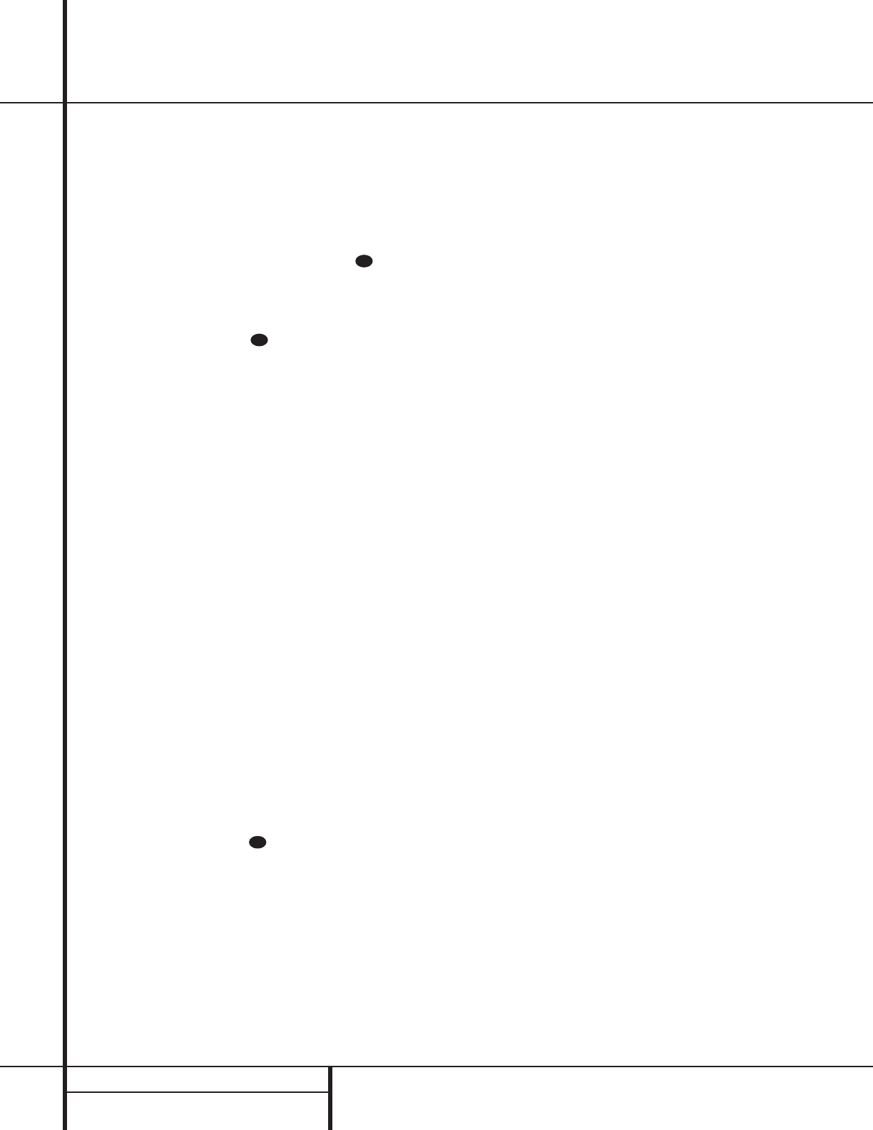
30 PROGRAMMING THE REMOTE
Programming the Remote
2. Press the Play button w.The Program
Indicator cwill stop flashing and stay
amber.
3. Press and release the Input Selector button
efor the device that will be used to change
the channels.The Program Indicator cwill
blink green three times and then go out to con-
firm the data entry.
Example: To control the transport of a DVD
player while the remote is set to control the TV,
first press the VID 2/TV Input Selector but-
ton eand the Mute button at the
same time. Next, release them and press the
Play button w, followed by the DVD Input
Selector button e.
NOTE: To remove the Channel Control Punch-
Through and return the remote to its original con-
figuration,repeat the steps shown in the example
above. However, press the VID 2/TV Input
Selector in Steps 1 and 3.
NOTE: Before programming the remote for
Volume,Channel or Transport Punch-Through,
make certain that any programming needed for
the specific TV, CD,DVD,Cable or Satellite
Receivers has been completed.
Reassigning Device Control
Selectors
Although each Input Selector eis normally
assigned to the category of product shown on the
remote, it is possible to reassign one of these but-
tons to operate a second device of another type.
For example,if you have two VCRs but no satellite
receiver, you may program the “SAT”button to
operate a second VCR. Before following the nor-
mal programming steps for either Three-Digit entry
or Auto Search code entry, you must first reassign
the button with the following steps:
1. Press the Input Selector eyou wish to
reassign and the Mute button at the
same time until the red light appears under the
Input Selector eand the Program
Indicator cflashes amber.
2. Press the Input Selector efor the device
you wish to program into the reassigned
button.
3. Enter the three-digit code for the specific
model you wish the reassigned button to
operate.
4. Press the same Input Selector epressed in
Step 1 once again to store the selection.The
red LED under the reassigned Input Selector will
flash three times and then go out.
Example: To use the CBL/SAT button to oper-
ate a second VCR, first press the CBL/SAT
Input Selector eand the Mute button
at the same time until the red light glows
under the CBL/SAT ebutton. Press the VCR
ebutton, followed by the three-digit code
for the specific model you wish to control.
Finally, press the CBL/SAT ebutton again.
Resetting the Remote Memory
As you add components to your home-theater sys-
tem, occasionally you may wish to totally repro-
gram the remote control without the confusion of
any commands, macros or ”Punch-Through“ pro-
gramming that you may have done.To do this,it is
possible to reset the remote to the original factory
defaults and command codes by following these
steps. Note, however, that once the remote is
reset, all commands or codes that you have
entered will be erased and will need to be re-
entered:
1. Press any of the Input Selector buttons e
and the ”O“ button rat the same time until
the Program Indicator cbegins to flash
amber.
2. Press the ”3“ button rthree times.
3.The red LED under the Input Selector ewill
go out and the Program Indicator cwill
stop flashing and turn green.
4.The Program Indicator cwill remain green
until the remote is reset. Note that this may
take a while,depending on how many com-
mands are in the memory and need to be
erased.
5.When the Program Indicator cgoes out,
the remote has been reset to the factory
settings.
35
35
35

31 FUNCTION LIST
Function List
No. Button Name AVR Function DVD CD/CDR Tape VCR (VID 1) TV (VID 1) CBL (VID 3) SAT (VID 3)
1Power Off Power Off Power Off Power Off Power Off Power Off Power Off Power Off Power Off
2Power On Power On Power On Power On Power On Power On Power On Power On Power On
3Mute Mute Mute Mute Mute Mute Mute Mute Mute
4AVR AVR Select
5DVD DVD Input Select DVD Select
6CD CD Input Select CD Select
7Tape Tape Input Select Tape Select
8VID 1 Video 1 Select VCR Select TV Select VID 3 Select
9VID 2 Video 2 Select
10 VID 3 Video 3 Select
11 VID 4 Video 4 Select
12 AM/FM Tuner Select
13 Sleep Sleep Channel + Channel + Channel +
14 Test Test Tone Input Select
15 TV TV/DVD CDP Select TV/VCR TV/VCR TV/Cable TV/Sat
16 Volume Up Volume Up Input Level Up Volume Up Volume Up Volume Up Volume Up
17 Surround Select
Surround Mode Select
CDR Select Channel – Channel – Channel –
18 Night Night Mode Select
19 Spare
20 Volume Down Volume Down
Input Level Down
Volume Down Volume Down Volume Down
21 Channel/Guide Channel Trim Title Info/Guide Info/Guide
22 Speaker/Menu Speaker Adjust Menu Menu Menu Menu Menu
23
⁄
Move/Adjust Up Up Up Up Up Up
24
fi
Move/Adjust Left Left Left Left Left Left
25 Set Set Enter Enter Enter Enter Enter
26
fl
Right Right Right Right Right
27
¤
Move/Adjust Down
Down Down Down Down Down
28 Digital/Exit
Digital Input Select
Subtitle Exit Exit Exit Exit
29 Delay/Prev. Ch. Delay Adjust Return Time Prev Channel Prev Channel Prev Channel
30 111 1 1 1 1
31 222 2 2 2 2
32 3
‡fi
33 3 3 3 3
33 4
fl·
44 4 4 4 4
34 555 5 5 5 5
35 6 66 6 6 6 6
36 777 7 7 7 7
37 888 8 8 8 8
38 Tun-M Tuner Mode
39 999 9 9 9 9
40 000 0 0 0 0
41 Memory
42 Tune Up Tune Up Next Chapter
43 Direct Direct Tuner Entry Track Direct
44 Clear Clear Clear Clear Clear Clear Clear Clear
32 FUNCTION LIST
Function List (continued)
45 Preset Up Preset Tune Up Slow Forward
46 Tune Down Tune Down Prev Chapter
Track Increment
47 D. Skip Disc Skip Disc Skip Stop Stop
48 Preset Down
Preset Tune Down
Slow Rev Intro Scan
49 M1 Open/Close Open/Close Cancel Sleep PPV Cancel
50 M2
Subtitle On/Off
Repeat Fav Fav
51 M3 Audio Select Random Play Bypass Next
52 M4 Angle Select Music Alt
53 Rewind R. Search R. Search Rewind Rewind Day – Say –
54 Play Play Play Play Play
55 Fast Forward F. Search F. Search Fast Fwd Fast Fwd Day + Day +
56 Record Record Record Record
57 Stop Stop Stop Stop Stop
58 Pause Pause Pause Pause Pause
59 Skip Down Skip – Skip – Scan – Page – Page –
60 Skip Up Skip + Skip + Scan + Page + Page +
No. Button Name AVR Function DVD CD/CD-R Tape VCR (VID 1) TV (VID 1) CBL (VID 3) SAT (VID 3)

33 SETUP CODES
Setup Code Table: TV
Manufacturer/Brand Setup Code Number
A MARK 097
ADMIRAL 069 192
AKAI 001 160
AMPRO 070
AMSTRAD 053
ANAM 045 055 057 076 095 097 099 106 109 112
AOC 001 011 097
BELL & HOWELL 069
BROKSONIC 091
CANDLE 001 002 003 011
CAPEHART 059
CENTURION 170 171
CENTRONIC 045
CITIZEN 001 002 003 011 045 092
CLASSIC 045
CONCERTO 011
CONTEC 041 045 051 052
CORANDO 172
CRAIG 045 055 157 158 159
CROWN 045
CURTIS MATHES 001 011 092
DAEWOO 011 022 023 045 046 056 068 102 108 111 114 116 118 119 127
DAYTRON 011
DYNASTY 045
DYNATECH 063
ELECTROHOME 074
EMERSON 001 011 012 013 029 033 045 048 049 051 052 091 137 139 141 157 158 162
ENVISION 001
FISHER 013 058
FUNAI 033 045
FUTURETECH 045
GE 001 011 014 015 057 070 071 133 141 145 163 199
GOLDSTAR 011 093 097 101 104 110 113 118
GRUNDIG 193
HALL MARK 011
HARMAN KARDON 201
HITACHI 001 011 015 016 017 018 029 043 072 144 147
INFINITY 148
INKEL 120
JBL 148
JC PENNEY 001 011 014 015 035 092 145
JENSEN 019
JVC 040 079 134
KEC 045
KENWOOD 001
KLOSS 002 060
KTV 001 045 162
LUXMAN 011
LXI 013 021 053 077 145 148
MAGNAVOX 001 003 011 060 061 064 065 118 145 148
MAJESTIC 069

34 SETUP CODES
Setup Code Table: TV (continued)
MARANTZ 001 074 148
MEMOREX 011 013 069
MGA 001 011 033 044 050 074
MIDLAND 199
MITSUBISHI 001 011 033 042 044 100 154 160 167 168
NAD 021 031
NATIONAL 177 178 179 180 181 182
NEC 001 013 022 025 042 057
OPTIMUS 031
OPTONICA 025 077
ORION 091
PANASONIC 039 057 076 087 148
PENNEY 199
PHILCO 001 003 011 045 057 060 061 064 065 118 148
PHILIPS 001 003 011 040 060 067 088 145 148
PIONEER 001 011 024 029 031 032
PORTLAND 011
PROSCAN 133
PROTON 011 059 165
QUASAR 057 087
RADIO SHACK 011 013 025 045 048 118 163 195 196 197 198
RCA 001 011 029 057 071 133 145 161 163 199
REALISTIC 013 025 045 048 163 195 196 197
RUNCO 052
SAMPO 001 011 059
SAMSUNG 001 011 012 051 085 092 096 104 118 124 145
SANSUI 091
SANYO 013 026 027 037 041 054 058 078
SCOTT 011 033 045 049
SEARS 011 013 021 033 035 058 078 092 145
SHARP 011 025 028 033 034 077 154
SIGNATURE 069
SONY 043 067 075 117 130 194
SOUNDESIGN 003 011 033 045
SSS 011 045
SUPRE MACY 002
SYLVANIA 001 003 011 060 061 064 065 118 145 148
SYMPHONIC 184
TANDY 077
TATUNG 057 063
TECHNICS 080
TECHWOOD 011
TEKNIKA 001 002 003 011 033 036 045 069 074 092
TELEFUNKEN 047
TELERENT 069
TMK 011
TOSHIBA 013 021 035 042 052 063 092 202
UNIVERSAL 014 015
VIDEO CONCEPTS 160
VIDTECH 011
WARDS 011 014 015 025 033 061 064 065 069 071 148
YAMAHA 001 011
ZENITH 069

35 SETUP CODES
Setup Code Table: VCR
Manufacturer/Brand Setup Code Number
AIWA 040
AKAI 022 048 050 108 109 126
AMPRO 076
AMSTRAD 133
ANAM 037 039 089
AUDIO DYNAMICS 018 029 044 048
BROKSONIC 031 041 043 110 147 166
CANDLE 134 135 137
CANON 034 037 039 135 140
CAPEHART 094
CITIZEN 021 045 134
CRAIG 003 045 116
CURTIS MATHES 037 039
DAEWOO 012 014 094 096 098 102
DAYTRON 094
DBX 018 029 044 048
DUAL 136
ELECTROHOME 063
EMERSON 013 023 031 033 035 037 040 041 042 043 050 087 110 112 119
FISHER 003 015
FUNAI 040 133
GE 037 039 067 076 093 095 124 127
GO VIDEO 113 117
GOLDSTAR 018 019 026 087 092 100 107
GRAETZ 136
HARMAN KARDON 018 049
HITACHI 011 040 048 067 130
INSTANTREPLAY 037 039
JC PENNEY 018 019 021 039 045 087
JENSEN 048
JVC 018 037 039 048 052 054 111 130 132
KENWOOD 020 044 048 052
LLOYD 040
LXI 019 020 040 087
MAGNAVOX 037 039 040 071
MARANTZ 018 037 039 071 073
MARTA 087
MEMOREX 003 020 037 039 040 057 076 087 115 120
MGA 049 050 063
MINOLTA 019 026
MITSUBISHI 019 026 049 050 053 055 063 131 145 146
MULTITECH 030 040
NAD 139
NATIONAL 140
NEC 018 029 044 048 052
NORDMENDE 048
OPTIMUS 057 087 159
OPTONICA 057 058
ORION 031 147 166
PANASONIC 074 078 086 114 150 167
PENTAX 019 026 037 039 067

36 SETUP CODES
Setup Code Table: VCR (continued)
PHILCO 037 039 040 071
PHILIPS 037 039 040 058 071 075 087
PILOT 087
PIONEER 019 027 052
PORTLAND 094
PULSAR 076
QUARTZ 002 020
QUASAR 039 144
RADIO SHACK 003 045 057 074 087 093 133 134 137 140 141 142 152 153 158 159 160 161
RCA 019 026 039 067 093 095 124 127 157
REALISTIC 003 015 020 037 039 040 045 057 058 087 093 137 152 159 160
RICO 028
SAMSUNG 038 045 088 090 091 093 095 098 101 105 106 109
SANSUI 028 031 048 052 116 147 166
SANYO 003 014 020 115
SCOTT 023 043 098 110 112
SEARS 003 015 019 020 026 037 087
SHARP 037 058 129 156
SHINTOM 030
SONY 003 037 056 060 061 080 081 082 129
SOUNDESIGN 040
STS 019
SYLVANIA 037 039 040 063 071
SYMPHONIC 040
TANDY 040
TATUNG 044 048
TEAC 040 044 048
TECHNICS 037 039
TEKNIKA 025 037 039 040 087
TMK 013
TOSHIBA 015 019 051 063 085 098 112 155
TOTEVISION 045 087
UNITECH 045
VECTOR RESEARCH 018
VICTOR 052
VIDEO CONCEPTS 018 040 050
VIDEOSONIC 045
WARDS 003 019 023 030 037 039 040 045 057 058 112
YAMAHA 018 040 044 048
ZENITH 040 052 060 076 083 087

37 SETUP CODES
Setup Code Table: CD
Manufacturer/Brand Setup Code Number
ADC 010
ADCOM 047 061 067
AIWA 079 109 116 126 154
AKAI 048 175 182
AUDIO TECHNICA 051
AUDIOACCESS 123
BSR 042 062
CALIFORNIA AUDIO 013 107
CAPETRONIC 068
CARRERA 062 085
CARVER 049 055 134 138 139 141 142 143 183 184
CASIO 064 115 120 164
CROWN 040
CURTIS MATHES 064
DENON 007 127 186 187
EMERSON 047 050 091 106
FISHER 021 032 053 055 066
FUNAI 124
GE 162
GOLDSTAR 014 085
HAITAI 097 214
HARMAN KARDON 001 002 023 038 052 188
HITACHI 047 091
INKEL 003 024 025
JC PENNEY 019 064 096 145
JENSEN 151
JVC 027 140 174 193 194
KENWOOD 012 018 021 028 060 076 077 146 149 174 176 177
KYOCERA 010
LOTTE 106
LUXMAN 016 033 075 100
LXI 064 162
MAGNAVOX 037 049 099 111 125
MARANTZ 041 049 056 082 189 190 191
MACINTOSH 192
MEMOREX 094
MGA 030
MISSION 049
MITSUBISHI 030 125
MITSUMI 150
NAD 011 072 125 195 196
NAKAMICHI 197 198 199
NEC 019 067
NIKKO 051 053
NSM 049
ONKYO 035 036 043 044 169 173 200 201 110 211
OPTIMUS 006 018 034 054 055 062 063 087 088 089 090 094 097 102
PANASONIC 013 073 107 117 156 181 202
PHILIPS 037 049 136 147 207
PIONEER 015 034 069 092 094 098 110 121 125 129 158 159 160 215
PROTON 049 208

38 SETUP CODES
QUASAR 013 107
RADIO SHACK 120 124
RCA 022 047 079 091 148
REALISTIC 047 054 055 056 091 093 102 103 106 162 163 164
ROTEL 049
SAE 049
SAMSUNG 026
SANSUI 045 049 079 132 155 170
SANYO 031 055 066 080 093 166
SCOTT 106
SEARS 064
SHARP 018 056 071 103 112 149 178
SHERWOOD 008 024 025 039 056 103 131
SIGNATURE 038
SONY 005 058 086 101 113 114 116 137 203 204 205 213
SOUNDSTREAM 122
STS 010
SYLVANIA 049
SYMPHONIC 057 108 163
TANDY 094
TEAC 009 020 046 056 083 084 104 105 108 119 135 144 152
TECHNICS 013 065 073 107 117 156 172 212
THETA DIGITAL 037
TOSHIBA 011 072 095 149 153 171
VECTOR RESEARCH 085
VICTOR 027 118 128
WARDS 038 093
YAMAHA 017 029 051 059 133 167
YORK 120 164
Setup Code Table: CD (continued)

39 SETUP CODES
Setup Code Table: DVD
Manufacturer/Brand Setup Code Number
CALIFORNIA AUDIO 032
DENON 002 019 022
GE 003 004
GOLDSTAR 005
HARMAN KARDON 001
JVC 006
KENWOOD 007
LOTTE 008
MAGNAVOX 009
MITSUBISHI 023 036
NAD 010
ONKYO 015
OPTIMUS 011
PANASONIC 024
PIONEER 012 020 035
RCA 018
RUNCO 027
SAMSUNG 031
SANYO 013
SHARP 021 028 037
SONY 014 029 034
TECHNICS 026
THOMSON 003 004
TOSHIBA 033
YAMAHA 016 017 030

40 SETUP CODES
Setup Code Table: SAT
Manufacturer/Brand Setup Code Number
ALPHASTAR 472
ALPHASTAR DBS 450
ALPHASTAR DSR 422
CHANNEL MASTER 317
CHAPARRAL 315 316 451
CITOH 360
DRAKE 317 318 413
DX ANTENNA 331 352 362 369
ECHOSTAR 319 322 364 380 395 396 452 453 463 467
ELECTRO HOME 392
EUROPLUS 415
FUJITSU 329
GENERAL ELECTRIC 408 474
GENERAL INSTRUMENT 301 303 311 323 365 403 454 468
HITACHI 372
HITACHI DBS 455
HOUSTON TRACKER 463 467
HUGHES 372 376 455
JANIEL 366
JERROLD 367 454 464 468
JERROLD PRIMASTER 456
KATHREIN 410
LEGEND 453
LUXOR 368
MACOM 317 365 371
MAGNAVOX 461 473
MEMOREX 453
NEXTWAVE 423 424
NORSAT 374
OPTIMUS 466
PANASONIC 366 469
PANASONIC DBS 457
PANSAT 420
PERSONAL CABLE 418
PHILIPS 375
PICO 407
PRESIDENT 381 404
PRIMESTAR 312 412 454 456 464
RCA 408 465 474
RCA DBS 458
REALISTIC 325 349 377
SAMSUNG 422
SATELLITE SERVICE CO 331 335 341 353
SCIENTIFIC ATLANTA 339
SONY 405
STAR CHOICE DBS 459
STARCAST 347
SUPER GUIDE 423 424
TEECOM 333 390 391 409
TOSHIBA 302 426 460 461 462 470
UNIDEN 323 324 325 332 348 349 350 354 355 381 382 383 389 403 466
ZENITH 371 384 385 387 394 419

41 SETUP CODES
Setup Code Table: CBL
Manufacturer/Brand Setup Code Number
ABC 001 003 045 048 052 059
ALLEGRO 111
AMERICAST 212
ANTRONIX 021
ARCHER 012 014 021 031 112
BELCOR 113
CABLE STAR 033 113
CENTURION 092
CENTURY 014
CITIZEN 014 111
COMTRONICS 026 037
DIAMOND 030
DIGI 114
EAGLE 027 037 046 186
EASTERN 063 066 070 115 187
ELECTRICORD 039
EMERSON 112
FOCUS 116
G.I. 001 003 015 017 093 095 096 097 126 141 168
GC ELECTRONICS 113
GE 076
GEMINI 015 029 032
GENERAL 110
GOLDEN CHANNEL 037
GOODMIND 112
HAMLIN 055 056 061 099 100 101 117 152 175 207 208
HITACHI 001 061 188
HOSPITALITY 074 080
JASCO 111
JERROLD 001 002 003 015 016 017 073 093 095 097 140 141 142 162 166 167 168 188 210
LINDAY 118
M-NET 043
MACOM 040 191
MAGNAVOX 017 019 068 082
MEMOREX 058
MOVIE TIME 035 039
NSC 022 035 044 075 190
OAK 023 043 059 094 196 197
PACE 160 179
PANASONIC 050 053 155 176 177 189 214
PANTHER 114
PARAGON 058
PHILIPS 013 019 020 027 085 090
PIONEER 001 041 057 119 147 148 171 200 209
POST NEWS WEEK 023
PRIMESTAR 162
PULSAR 058
RADIO SHACK 111 112 213
RCA 053 214
REALISTIC 012
RETOCON 116
REGAL 055 056 061 099 100 101 158 207

42 SETUP CODES
Setup Code Table: CBL (continued)
REGENCY 063 115 187
REMBRANT 032
SAMSUNG 037 072 186
SCIENTIFIC ATLANTA 003 018 047 048 052 130 145 183 203 204
SIGNAL 037
SIGNATURE 001 188
SPRUCER 053 081 177 189
STARCOM 002 015 016 141 163
STARGATE 015 037 120 187
SYLVANIA 071
TANDY 024
TELECAPATION 028
TEXSCAN 036 071
TFC 122
TIMELESS 123
TOCOM 045 046 062 170 205
TOSHIBA 058
UNIKA 014 021 031
UNITED CABLE 059
UNIVERSAL 012 014 021 031 033 034 039 042 113
VIDEOWAY 124 211
VIEWSTAR 019 022 025 190
ZENITH 058 065 098 125 211
ZENTEK 116

43 TROUBLESHOOTING GUIDE
Troubleshooting Guide
SYMPTOM CAUSE SOLUTION
Unit does not function when Main • No AC Power • Make certain AC power cord is plugged into
Power Switch is pushed a live outlet
• Check to see whether outlet is switch-controlled
Display lights, but no sound • Intermittent input connections • Make certain that all input and speaker connections
or picture • Mute is on are secure
• Volume control is down • Press Mute button
• Turn up volume control
Unit turns on, but front-panel • Display brightness is turned off • Follow the instructions in the Display Brightness section
display does not light up on page 31 so that the display is set to VFD FULL
No sound from any speaker; • Amplifier is in protection mode • Check speaker wire connections for shorts at receiver and
light around power switch is red due to possible short speaker ends
• Amplifier is in protection mode • Contact your local Harman Kardon service depot
due to internal problems
No sound from surround or • Incorrect surround mode • Select a mode other than stereo
center speakers • Input is monaural • There is no surround information from mono sources
• Incorrect configuration • Check speaker mode configuratioin
• Stereo or Mono program material • The surround decoder may not create center- or rear-channel
information from nonencoded programs
Unit does not respond to • Weak batteries in remote • Change remote batteries
remote commands • Wrong device selected • Press the AVR selector
• Remote sensor is obscured • Make certain front panel sensor is visible to remote
or connect remote sensor
Intermittent buzzing in tuner • Local interference • Move unit or antenna away from computers, fluorescent
lights, motors or other electrical appliances
Letters flash in the channel indicator • Digital audio feed paused • Resume play for DVD
display and digital audio stops • Check that Digital Input is selected
Processor Reset
In the rare case where the unit’s operation or
the displays seem abnormal, the cause may
involve the erratic operation of the system’s
memory or microprocessor.
To correct this problem, first unplug the unit
from the AC wall outlet and wait at least three
minutes. After the pause,reconnect the AC
power cord and check the unit’s operation. If
the system still malfunctions, a system reset
may clear the problem.
To clear the AVR 110’s entire system memory
including tuner presets, output level settings,
delay times and speaker configuration data,
first put the unit in Standby by pressing the
System Power Control button 2. Next,
press and hold the Tone Mode 6and the
FM Mode Selector @buttons for three
seconds.
The unit will turn on automatically and display
the RESET message in the Main
Information Display W. Note that once you
have cleared the memory in this manner, it is
necessary to reestablish all system configuration
settings and tuner presets.
NOTE: Resetting the processor will erase any
configuration settings you have made for
speakers, output levels, surround modes,digital
input assignments as well as the tuner presets.
After a reset the unit will be returned to the
factory presets, and all settings for these items
must be reentered.
If the system is still operating incorrectly, there
may have been an electronic discharge or
severe AC line interference that has corrupted
the memory or microprocessor.
If these steps do not solve the problem, consult
an authorized Harman Kardon service depot.

44 TECHNICAL SPECIFICATIONS
Technical Specifications
Audio Section
Stereo Mode
Continuous Average Power (FTC)
50 Watts per channel, 20Hz–20kHz,
@ <0.07% THD, both channels driven into 8 ohms
Five-Channel Surround Mode
Power per Individual Channel
Front L&R channels:
40 Watts per channel
@ <0.07% THD, 20Hz–20kHz into 8 ohms
Center channel:
40 Watts @ <0.07% THD, 20Hz–20kHz into 8 ohms
Surround channels:
40 Watts per channel
@ <0.07% THD, 20Hz–20kHz into 8 ohms
Input Sensitivity/Impedance
Linear (High-Level) 200mV/47k ohms
Signal-to-Noise Ratio (IHF-A) 95dB
Surround System Adjacent Channel Separation
Analog Decoding 40dB
(Pro Logic, etc.)
Dolby Digital (AC-3) 55dB
DTS 55dB
Frequency Response
@ 1W (+0dB, –3dB) 10Hz–100kHz
High Instantaneous
Current Capability (HCC) ±25 Amps
Transient Intermodulation
Distortion (TIM) Unmeasurable
Rise Time 16 µsec
Slew Rate 40V/µsec
FM Tuner Section
Frequency Range 87.5–108MHz
Usable Sensitivity IHF 1.3µV/13.2dBf
Signal-to-Noise Ratio Mono/Stereo 70/68dB
Distortion Mono/Stereo 0.2/0.3%
Stereo Separation 40dB @ 1kHz
Selectivity ±400kHz, 70dB
Image Rejection 80dB
IF Rejection 90dB
Tuner Output Level 1kHz, ±75kHz Dev 500mV
AM Tuner Section
Frequency Range 520–1710kHz
Signal-to-Noise Ratio 45dB
Usable Sensitivity Loop 500µV
Distortion 1kHz, 50% Mod 0.8%
Selectivity ±10kHz, 30dB
Video Section
Television Format NTSC
Input Level/Impedance 1Vp-p/75 ohms
Output Level/Impedance 1Vp-p/75 ohms
Video Frequency
Response 10Hz–8MHz (–3dB)
General
Power Requirement AC 120V/60Hz
Power Consumption 72W idle,580W maximum
(2 channels driven)
Dimensions
Width 17.3 inches (440mm)
Height 6.5 inches (165mm)
Depth 17.1 inches (435mm)
Weight 31 lb (14.1kg)
Depth measurement includes knobs, buttons and terminal connections.
Height measurement includes feet and chassis.
All features and specifications are subject to change without notice.
Harman Kardon is a registered trademark,and Power for the digital revolution is a trademark, of
Harman Kardon, Inc.
*Manufactured under license from Dolby Laboratories.
“Dolby,”“Pro Logic,”“AC-3” and the Double-D symbol are
trademarks of Dolby Laboratories. Confidential Unpublished
Works. ©1992–1999 Dolby Laboratories, Inc.All rights reserved.
DTS and DTS Surround are trademarks of Digital Theater Systems, Inc.
UltraStereo is a trademark of UltraStereo Corp.
VMAx is a registered trademark of Harman International Industries, Inc.,and is an
implementation of Cooper Bauck Transaural Stereo under patent license.
Logic 7 is a registered trademark of Lexicon,Inc., a Harman International Company.
Crystal is a registered trademark of Cirrus Logic Corp.

45 NOTES
Notes

46 NOTES
Notes

47 NOTES
Notes

250 Crossways Park Drive,Woodbury, New York 11797
www.harmankardon.com
© 2000 Harman Kardon, Incorporated
Part No.: J90200012600