Harman Stove Company The Accentra Pellet Insert Users Manual 2
The Harman Accentra Pellet Insert to the manual a818ca88-76a6-427e-a9e6-83a6294d8e36
2015-02-09
: Harman-Stove-Company Harman-Stove-Company-The-Harman-Accentra-Pellet-Insert-Users-Manual-563946 harman-stove-company-the-harman-accentra-pellet-insert-users-manual-563946 harman-stove-company pdf
Open the PDF directly: View PDF ![]() .
.
Page Count: 37
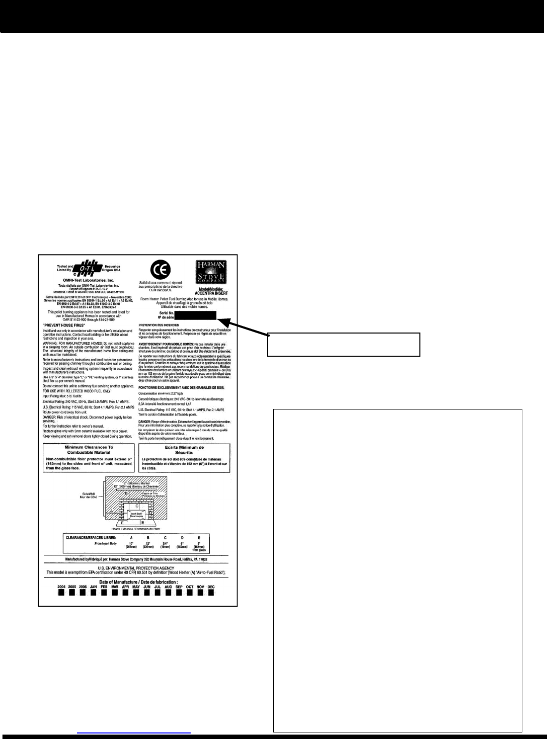
SAFETY NOTICE
PLEASE READ THIS ENTIRE MANUAL BEFORE YOU INSTALL AND USE YOUR NEW ROOM HEATER. FAILURE TO
FOLLOW INSTRUCTIONS MAY RESULT IN PROPERTY DAMAGE, BODILY INJURY, OR EVEN DEATH.
FOR USE IN THE U.S. AND CANADA. SUITABLE FOR INSTALLATION IN MOBILE HOMES
IF THIS HARMAN ACCENTRA PELLET INSERT IS NOT PROPERLY INSTALLED, A HOUSEFIRE MAY RESULT. FOR
YOUR SAFETY, FOLLOW INSTALLATION DIRECTIONS.
CONTACT LOCAL BUILDING OR FIRE OFFICIALS ABOUT RESTRICTIONS AND INSTALLATION INSPECTION
REQUIREMENTS IN YOUR AREA.
CONTACT YOUR LOCAL AUTHORITY (SUCH AS MUNICIPAL BUILDING DEPARTMENT, FIRE DEPARTMENT, FIRE
PREVENTION BUREAU, ETC.) TO DETERMINE THE NEED FOR A PERMIT.
CETTE GUIDE D'UTILISATION EST DISPONIBLE EN FRANCAIS. CHEZ VOTRE CONCESSIONNAIRE DE HARMAN STOVE
COMPANY.
SAVE THESE INSTRUCTIONS.
The Harman Accentra Pellet Insert
Installation & Operating Manual
R3
“Ce manuel est disponible en Français sur demande”
Evaluation notes were added to the output document. To get rid of these notes, please order your copy of ePrint IV now.
3
Introduction
Harman Stove Company
352 Mountain House Road
Halifax, PA 17032
sales@harmanstoves.comsales@harmanstoves.com
Table of Contents
Automatic Operation 4
Manual Operation 6
ESP Control 8
Assembly & Installation 9
Venting 21
Maintenance 28
Trouble-Shooting 33
Specifications 34
Wiring Diagram 35
Feeder Parts 36
Parts List 37
Warranty 38
The Accentra Insert will give you more heat, better temperature control and a level of convenience you won’t find in any other
pellet insert. The Accentra Insert’s many outstanding features make it the best value pellet insert on the market today.
The Accentra’s versatile design lets you convert a heat wasting fireplace into an efficient heating source. The Accentra Insert
could also be a fireplace hearth for your home that doesn’t require a chimney. A special zero clearance fireplace kit converts the
Accentra insert into a fireplace that can be placed in virtually any corner or against any wall of your home. You can choose from
a variety of mantels and facings that complement your homes décor.
The Accentra’s on-board microprocessor constantly senses room temperature and automatically makes adjustments in the feed
rate and air supply so you get just the right amount of heat 24 hours a day. This remarkable technology lets you fill the hopper,
set the desired temperature and walk away. The Accentra insert lights automatically, brings the room up to the exact temperature
and will turn off if no heat is required. No other pellet insert offers such accurate and trouble free temperature control. The control
technology gives you the widest heat output range of any insert on the market making it an ideal choice to take the chill off in the
spring and fall and to heat your home during the coldest months of the winter.
As with all Harman pellet stoves, maintenance is minimal and cleaning is easy. The Accentra Insert lets you burn close to a ton of
pellets before ash removal is needed. And what is even better, the Harman Insert Track System lets you slide the insert out of the
fireplace so that it can be cleaned or serviced without having to disconnect the venting system. This innovative design is only
available on Harman pellet inserts and lets you reach key components for yearly cleaning.
SAFETY NOTICE: IF THIS HARMAN STOVE IS NOT PROP-
ERLY INSTALLED. A HOUSE FIRE MAY RESULT. FOR
YOUR SAFETY, FOLLOW THE INSTALLATION DIREC-
TIONS CONTACT LOCAL BUILDING OR FIRE OFFICIALS
ABOUT RESTRICTIONS AND INSTALLATION INSPECTION
REQUIREMENTS IN YOUR AREA.
Please copy you r
serial number from the
label on your stove to
the box below.
SERIAL NUMBER
Evaluation notes were added to the output document. To get rid of these notes, please order your copy of ePrint IV now.
4
Starting First Fire
Igniter Switch to"AUTO" (up position)
Make sure the unit is plugged into a 120 VAC,
60 HZ electrical source. The power light should
be the only light lit.
1. Turn Mode Selector to "OFF".
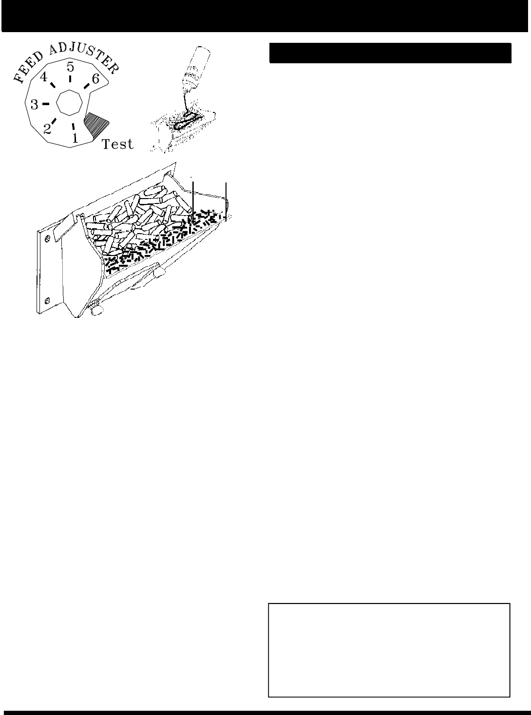
2. Fill hopper with pellets.1
3. Clean burn pot with scraper, if necessary.5
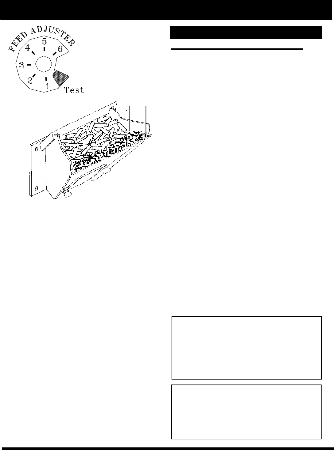
4. If starting after an empty hopper, turn Feed
Adjuster to "TEST" (for one 60 second cycle).2
This will purge pellets into the auger tube and also
allow you to check the motors for operation. NOTE:
The auger motor will not operate with the view
door or ash pan door open.3
5. Turn Feed Adjuster to #4.4
6. Flip the Igniter Switch up into the "AUTO"
position.
7. Turn the Temperature Dial to desired room
temperature.
8. Turn Mode Selector to Room Temperature or
Stove Temperature.
9. Fill hopper with pellets and remove ashes as
required.6
10. Store pellet fuel in a dry area away from all
ignition sources and above all limits of the stove's
clearance requirements to combustibles. Do not
store the fuel were it interferes with the refueling
of the stove or emptying of ashes. Do not store
any ashes removed from the stove near the fuel
or other combustible materials.
Automatic Start Up
1. Fines are small pieces of broken pellets (sawdust). Fines do
not flow easily and often build up on the hopper funnel bottom
angles. These fines can be pushed into the feeder opening
and then fill the hopper with pellets. As the system works, they
will be burned.
2. The "TEST" cycle will operate the feeder motor for exactly
one minute. Turning to "TEST" again and again may purge too
much fuel into the burn pot causing excessive smoke on start-
up.
3. The firebox low pressure switch will not allow the auger motor
or the igniter element to operate if the view door is open.
4. Adjust Feed Rate. If this is your first fire or you are trying
different pellets, set the feed adjuster to #4, Fig. 1. This is a
conservative number and will probably need to be increased.
After you know a feed rate setting that works well, use that
setting. Remember, if your feed rate is too high you may waste
fuel.
5. This is usually a weekly maintence procedure. Cleaning the
burn pot with the scraper with a small amount of new fuel in the
bottom is not a problem. First, scrape the ashes on the front of
the burn pot into the ash pan. Then scrape the holed surface
downward into the burn pot. When the stove is ignited these
scrapings will be pushed out by the feeder.
6. The ash pan can hold the ashes from approximately 1 ton of
premium fuel. This means the ashes will only need to be
emptied a few times a year.
7. Setting the feed adjuster # for maximum burn: With the unit
burning in "AUTO", turn to "Stove Mode" and put the fan on "H".
Set the Temperature Dial to #7. Allow the unit to burn for about
30 minutes and check ash on front of burn pot. Fig. 4. If the ash
line is larger than 1", turn the feed adjuster from #4 to #5. Allow
another 30 minutes of burn time and check again. If , at #6
setting, a 1" or less ash bed is not obtainable, it is not a problem.
The 1" ash bed is only a maximum burn rate and at most
normal settings the ash bed will be larger.
See Note 7.
Fig. 2
1"
NEVER USE GASOLINE, GASOLINE-TYPE LANTERN
FUEL, KEROSENE, CHARCOAL LIGHTER FLUID,
OR SIMILAR LIQUIDS TO START OR 'FRESHEN UP'
A FIRE IN THIS HEATER. KEEP ALL SUCH LIQUIDS
WELL AWAY FROM THE HEATER WHILE IN USE.
WARNING
Fig. 1
WARNING
BURNING GARBAGE, USE OF IMPROPER FUELS,
FIRE STARTERS OR ALTERING THE STOVE FOR
HIGHER HEAT OUTPUT MAY CAUSE DAMAGE TO
THE STOVE AND COULD RESULT IN A HOUSE FIRE.
USE ONLY APPROVED FUELS AND OPERATION
GUIDELINES.
Evaluation notes were added to the output document. To get rid of these notes, please order your copy of ePrint IV now.
5
The Accentra Insert is more than just automatic ignition, it is also automatic temperature
control. The automatic system will allow the fire size to be adjusted to match the heating
needs and even put the fire out if necessary. If heat is needed after the fire is out, the
Accentra Insert will automatically re-ignite and adjust the fire size to match the heating
need. The totally automatic room sensor mode is recommended because of its efficiency.
The unit can be switched between "AUTO" and "MANUAL" at any time during operation.
Igniter switch to "AUTO"
Room Temperature Mode
In "Room Temp Mode" heat output is controlled au-
tomatically by the Room Sensing Probe. When the Room
Sensing Probe calls for heat, the stove will increase out-
put. When the Room Sensing Probe is getting close to
the set temperature, the stove will begin to level off out-
put and keep the fire burning at just the right temperature
to maintain that setting.
High output is determined by the feed rate set-
ting. This setting, generally on #4, can be increased if
higher burn rates are necessary (Fig. 1). The unit's maxi-
mum burn rate should not create less than 1" of ash on
the burn pot front edge(See Fig.2). Overfeeding is not a
safety concern, but fuel may be wasted if unburned pel-
lets fall into the ash pan.
In "Room Temp Mode" a constant fuel consumption
rate is sacrificed for exact room temperature. Therefore,
as it gets colder more pellets will be burned automati-
cally.The distribution blower speed will vary according to
the position of the mode selector pointer, and fire size.
Igniter switch to "AUTO"
Stove Temperature Mode
This allows for automatic ignition upon start-up only.
The unit can then be set at any desired setting. The heat
output and fuel consumption will remain constant regard-
less of room temperature (See Fig 4). The unit's maxi-
mum feed rate should not create less than 1" of ash on
the burn pot front edge. See Fig 2.
The unit's low burn or maintenance setting is as low
as it will go. It will not go out unless it runs out of fuel or is
turned off.
Shut-Down Procedure
To kill the fire or stop burning the stove, turn the Mode
Selector to "OFF". This will cause the fire to diminish and
burn out. When the fire burns out and the stove cools
down everything will stop.
If you pull the plug to shut down the stove, all motors
will stop. This may cause incomplete combustion and
smoke in the firebox. If the load door is opened the smoke
may escape.
The best way to shut down the stove is simply let it
run out of pellets, then the stove will shut down automati-
cally.
Automatic Ignition/Operation
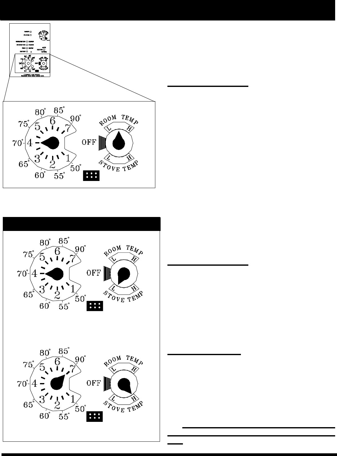
Fig. 4
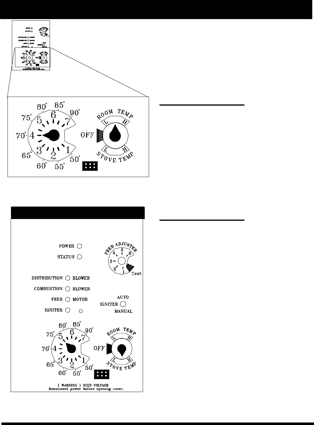
Room Temperature Mode: This setting will produce a room
temperature of 70 degrees with the distribution blower at medium
speed.
This setting will produce medium heat with the
distribution blower on "low".
This setting will produce continuous maximum heat
output with the distribution blower at full speed.
Stove Temperature Mode
Fig. 3
Evaluation notes were added to the output document. To get rid of these notes, please order your copy of ePrint IV now.
6
Manual Start Up
Starting First Fire
Igniter Switch to"MANUAL" (down position)
Make sure the unit is plugged into a 120
VAC, 60 HZ electrical source. The power light
should be the only light lit.
1. Turn FEED ADJUSTER to desired feed
rate. No. 4 is good for most pellets.4
2. Turn the MODE SELECTOR to “OFF” and
then to the desired mode. This will reset
control and start the combustion motor.
3. Turn the TEMPERATURE DIAL to the de-
sired setting.
4. Clean burn pot with scraper if necessary.5
5. Fill burn pot with pellets, only level with
front edge. (Do Not Over Fill).
6. Add starting gel on top of the pellets. Stir
gel into pellets for fast lighting.
7. Light starting gel with a match, and close
the door. Operation will begin when the fire
reaches the proper temperature.3
8. Fill hopper with pellets and remove ashes
as required.1, 6
1. Fines are small pieces of broken pellets (sawdust). Fines
do not flow easily and often build up on the hopper funnel
bottom angles. These fines can be pushed into the feeder
opening and then fill the hopper with pellets. As the system
works, they will be burned.
2. The "TEST" cycle will operate the feeder motor for exactly
one minute. Turning to "TEST" again and again may purge too
much fuel into the burn pot causing excessive smoke on start-
up.
3. The firebox low pressure switch will not allow the auger
motor or the igniter element to operate if the view door or the
ash pan door are open.
4. Adjust Feed Rate. If this is your first fire or you are trying
different pellets, set the feed adjuster to #4, Fig. 5. This is a
conservative number and will probably need to be increased.
After you know a feed rate setting that works well, use that
setting. Remember, if your feed rate is too high you may waste
fuel.
5. This is usually a weekly maintence procedure. Cleaning the
burn pot with the scraper with a small amount of new fuel in the
bottom is not a problem. First, scrape the ashes on the front of
the burn pot into the ash pan. Then scrape the holed surface
downward into the burn pot. When the stove is ignited these
scrapings will be pushed out by the feeder.
6. The ash pan can hold the ashes from approximately 1 ton of
premium fuel. This means the ashes will only need to be
emptied a few times a year.
7. Setting the feed adjuster # for maximum burn: With the unit
burning in "AUTO", turn to "Stove Mode" and put the fan on "H".
Set the Temperature Dial to #7. Allow the unit to burn for about
30 minutes and check ash on front of burn pot. Fig. 9. If the ash
line is larger than 1", turn the feed adjuster from #4 to #5. Allow
another 30 minutes of burn time and check again. If , at #6
setting, a 1" or less ash bed is not obtainable, it is not a
problem. The 1" ash bed is only a maximum burn rate and at
most normal settings the ash bed will be larger.
Fig. 6
Fig. 7
1"
See Note 7.
NEVER USE GASOLINE, GASOLINE-TYPE LANTERN
FUEL, KEROSENE, CHARCOAL LIGHTER FLUID, OR
SIMILAR LIQUIDS TO START OR 'FRESHEN UP' A
FIRE IN THIS HEATER. KEEP ALL SUCH LIQUIDS
WELL AWAY FROM THE HEATER WHILE IN USE.
Warning
Notice when using Optional Battery Back-Up:
If a power outage is expected, change the toggle
switch to Manual Mode. The Harman 502H Battery
Backup is incapable of powering the igniter. If an
automatic ignition is attempted while the stoves is
being powered by the battery back up, it may cause
damage to both the stove and the battery backup
unit.
Fig. 5
Evaluation notes were added to the output document. To get rid of these notes, please order your copy of ePrint IV now.
7
The Accentra Insert is capable of manual operation. This also allows the operator to
manually control operation during an emergency (i.e. igniter failure, when using a 502H
battery backup, or when using certain generators.)
The unit can be switched between "AUTO" and "MANUAL" at any time during operation.
Igniter Switch to "MANUAL"
Room Temperature Mode
The fire will have to be lit with starting gel and a
match, or started automatically, see "Automatic Opera-
tion". Turn to "Manual" position when the fire is estab-
lished.
The difference between "AUTO" Room Tempera-
ture Mode and "Manual" Room Temperature Mode is
that the fire will not go out as the room temperature goes
above the control board setting. The unit can only go to
low burn and will remain there until it runs out of fuel or
until more heat is needed and the feed rate increases.
Feed rate adjustments and dial settings are the same
as "AUTO" settings.
Igniter Switch to "MANUAL"
Stove Temperature Mode
The advantage of this mode is to allow the opera-
tor to have a large viewing fire without blowing extra heat
into the room.
During operation, with the temperature dial set at
#5 or less, the distribution fan will not operate. A #5 on
the temperature dial and a #5 on the feed adjuster is
approximately 80% output. It is not necessary to oper-
ate the distribution blower below this point. Therefore,
there can be a higher feed rate ( a larger viewing fire)
without an excess of hot air blowing into the room.
An example of when to use the Manual Stove Tem-
perature Mode is if you want to watch a large fire and
the room is aleady up to temperature. The Stove Tem-
perature Mode allows you to have a larger fire and a
lower sound level, without the distribution blower.
NOTE: During the use of this mode, if you keep
increasing the temperature dial setting to increase
the fire size, the distribution blower will automati-
cally come on when the ESP Temperature reaches
350o F, or 81% output.
NOTE: When starting the unit in the "AUTO"
mode and switching to "MANUAL", the fire must be
large enough to start the distribution blower. The
starting of the blower is a signal that the start cycle
is completed and the fire will not go out.
Manual Ignition/Operation
Room Temperature Mode: This setting will produce a room
temperature of 70 degrees with the distribution blower at medium
speed.
This setting will produce a large viewing fire without a
distribution blower operating.
Fig. 9
Manual Stove Temperature Mode
Fig. 8
Evaluation notes were added to the output document. To get rid of these notes, please order your copy of ePrint IV now.
8
ESP Control
Status light error messages:
1 Blink: Indicates control board self diagnostic fail-
ure. This requires a manual reset*.
3 Blinks: Indicates ESP (Exhaust Sensing Probe)
failure. This requires a manual reset*.
4 Blinks: Can occur only in Room Temp Mode and
indicates Room Sensing Probe failed or not in-
stalled. If a Room Sensing Probe is then installed,
the status light will automatically reset.
NOTE: Unit will not start in "AUTO" with this status
error.
5 Blinks (In Igniter Auto. Mode Only): Indicates
that the unit has failed to light within the 36 minute
start cycle. To reset - Turn Mode Selector to "OFF",
then turn to either mode again.)
6 Blinks : Indicates that the control has calculated
poor or incomplete combustion occurring for more
than 50 minutes.
A six blink status may be set if the stove is allowed
to run out of pellets. To reset, turn mode selector to
"OFF" then back on to the desired mode. If the unit
was not out of pellets, see Troubleshooting section,
Page 24, for more details.
* Manual reset- disconnect power cord for a few
seconds and reconnect. If error still occurs call your
Dealer.
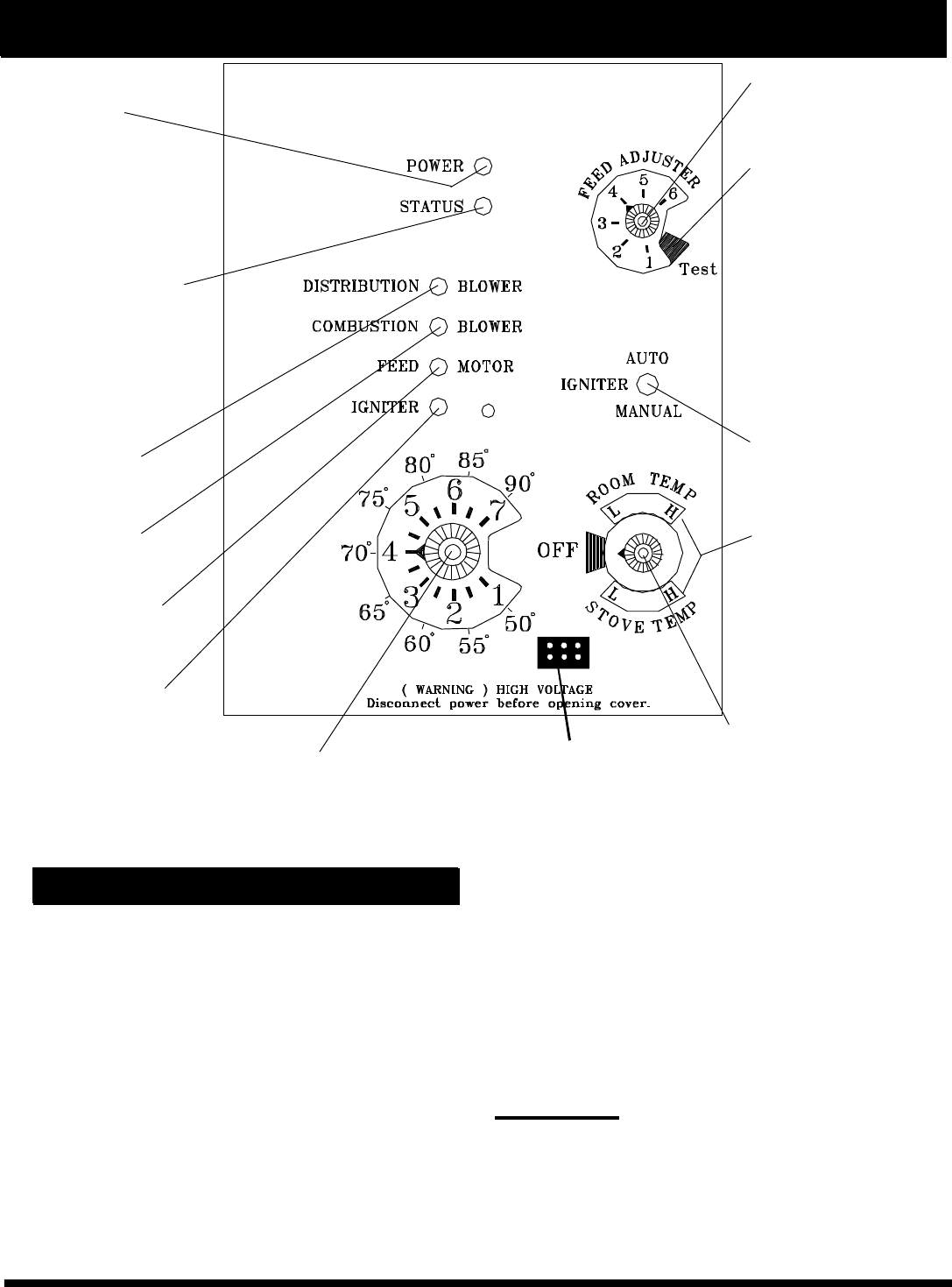
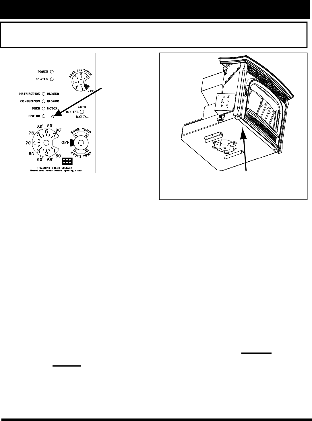
Feed adjuster
Sets the maximum
feed rate
Test
Runs all motors at full
speed for one minute
to check operation.
After two minutes the
stove will go to
minimum burn and
the blowers will
alternate from high to
low every minute to
remind you that you
are still in "Test
Mode".
Igniter switch
Set to appropriate
Start-Up mode.
Distribution Blower
speed adjustment range.
L = low
H = high
Variable speed anywhere
between L and H;
although as the stove
temp. goes up , so does
the L and H scale.
Temp dial
Allows you to adjust the room temperature in Room Temp
Mode using the outer scale marked in degrees Fahrenheit.
It also allows you to adjust the stove temperature while in
Stove Temp Mode using the inner scale marked from 1 to 7.
Mode Selector
Allows you to choose between
Room Temp Mode, Stove
Temp Mode, or OFF. Also
allows you to vary the
distribution blower speed by
turning the knob to the high
or low side of each mode.
Power Light
Indicates power to the
control.
Indicates power to the
feed motor.
Indicates igniter is on.
Indicates power to
combustion blower
Status Light
Will be lit in either stove
or room temp mode when
pointer is not within off
position band except
after normal shut down.
Blinks to indicate errors
listed below.
Indicates power to
distribution blower.
Dealer Diagnostic Port
For dealer maintenance
only. Requires special DDM
monitor supplied to Harman
Dealers exclusively.
Evaluation notes were added to the output document. To get rid of these notes, please order your copy of ePrint IV now.
9
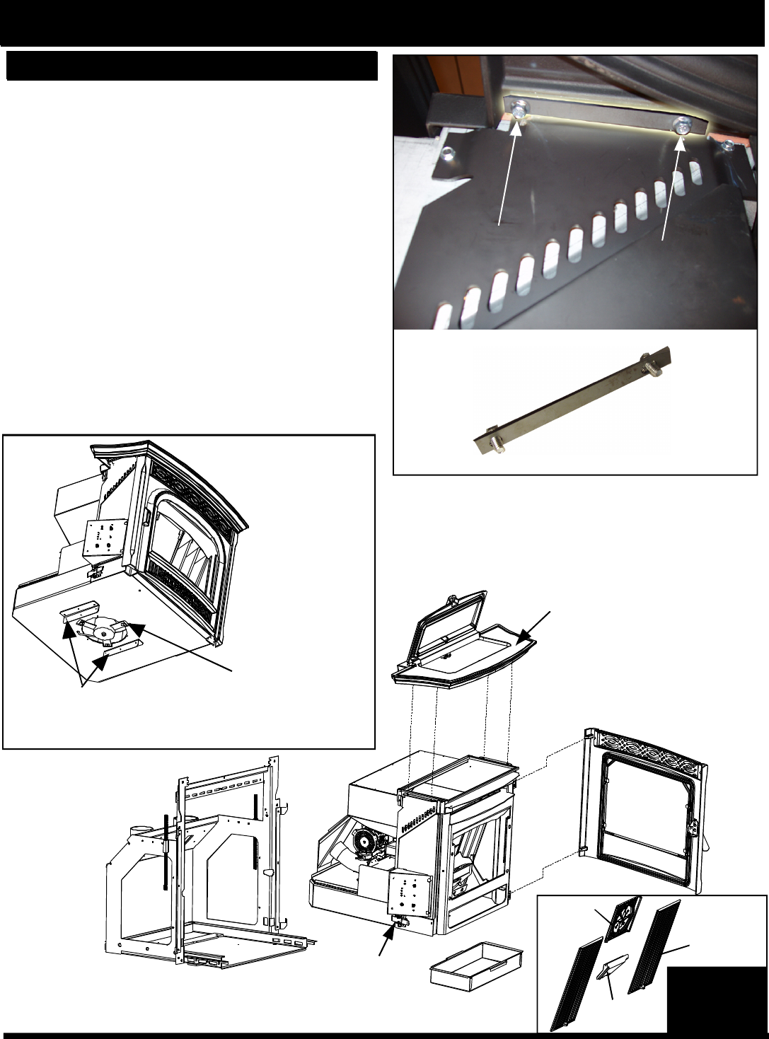
Top and Lid Assembly
Center
Medallion
Flame Guide
Heat
Exchanger
Cover
Ash Pan
(2) Spring Latches
(One on each side)
Fig. 11
Installation: Removing unit from skid
How to Reduce the Weight for Installation
1. Remove the top/lid assembly and side panels.
• Note: Removal of the cast hopper lid itself is
NOT necessary or recommended.
• Note: The hopper lid must be in the "OPEN" position
before the top/lid assembly can be lifted off or
reinstalled on the stove body.
• There are (4) 1/4-20 x 1/2" flange head bolts securing
the top/lid assembly to the stove body. They can be
removed from the underside with a 3/8" socket.
The cast top and lid assembly bolt down bars:
On each side of the stove body, underneath the cast
top, are (2) 1/4" flange head bolts.See Fig. 12.
These bolts pull the cast top and lid assembly down
onto the hopper gasket to seal the hopper.
They also allow for a small amount of front to back
adjustment for alignment of the top into the wing
pockets.
Internal
Cast Iron
(4) pieces
Mounting Shell
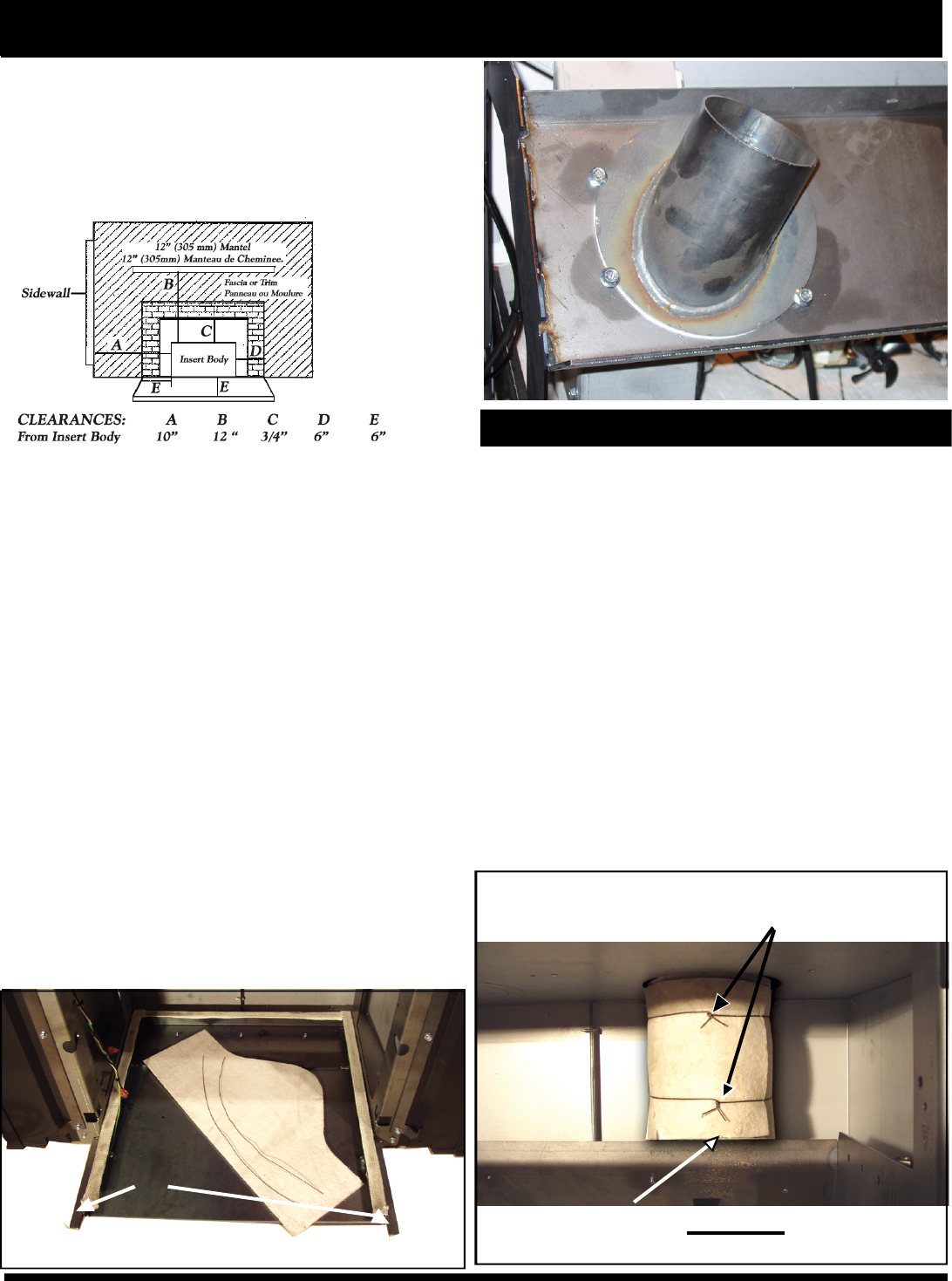
Protector Angles: These angles are designed to
protect the blower motor from damage when
placed on a flat surface. Be careful where and
how the stove body is handled.
Be careful not to
damage the
distribution blower
located under the
insert. There are
guards on both
sides of the motor
to allow the insert
to rest on a flat
surface, however,
extra care should
be taken.
Distribution Blower
Bolts require a
3/8" socket.
(View looking up under the cast top.)
Top bolt down bar
Fig. 10
Fig. 12
Remove the cast side panels by lifting them upward
off of the hinge pins. See Fig. 13.
Evaluation notes were added to the output document. To get rid of these notes, please order your copy of ePrint IV now.
10
Installation
2. Remove the door by swinging it open approximately
90o and lift it upward until it clears the hinge pins.
3. Remove the ash pan
4. Remove the (4) internal pieces of cast iron. See Fig.
14 and 15.
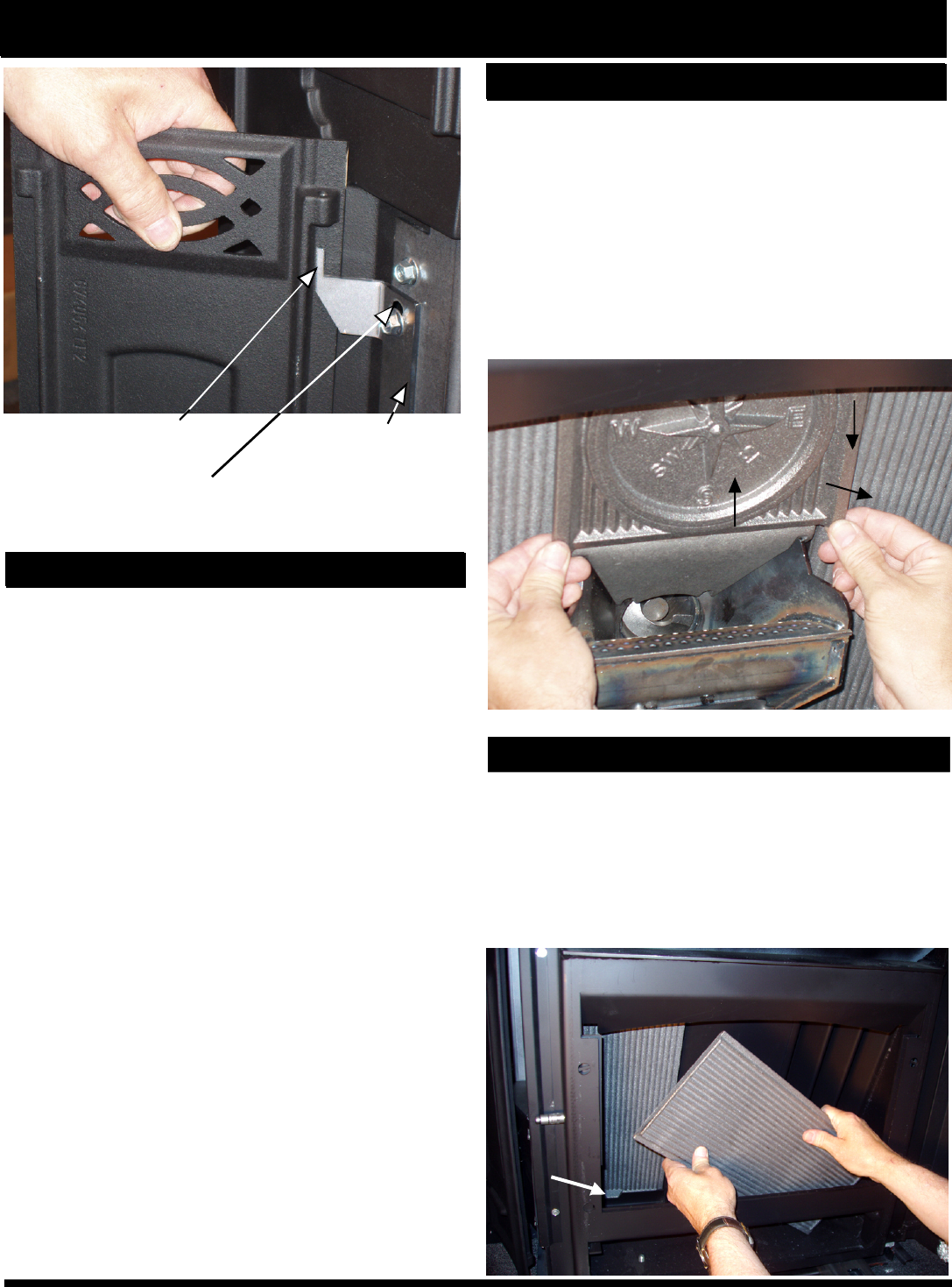
How to Reduce the Weight for Installation, cont'd
Removing the Center Medallion
• Lift up on the 2 bottom corners of the medallion until
it is higher than the top of the flame guide.
• Pull the bottom edge of the medallion front approxi-
mately 1 inch.
• Pull downward on the corners of the medallion until
the top is released from the 2 retainers that keep the
top aligned when in place.
• Note: The heat exchanger covers will tilt to the front
when the center medallion is removed.pproximatlely
12”, but the left side tube requires the total length of the
brush to be used.
Removing the Heat Exchanger Covers
• Remove the heat exchanger cover by lifting it upward
about 1/2 inch and move the bottom edge front until it
sits flat on the firebox bottom.
• Rotate the edge of the heat exchanger closest to the
burnpot until it is in front of the burnpot.
• Tip the top of the heat exchanger toward the middle of
the opening until it can be lifted up and out.
Center Medallion
Flame guide
Burn Pot
3rd: DOWN
3rd: DOWN
1st:UP 2nd: OUT
2nd: OUT
1st:UP
Fig. 14
Lasered hinge pin
pivoting point
Up and down clearance
adjustment slots.
Cast side
panel hinge
Fig. 13
Lifting tab
Fig. 15
Evaluation notes were added to the output document. To get rid of these notes, please order your copy of ePrint IV now.
11
Installation
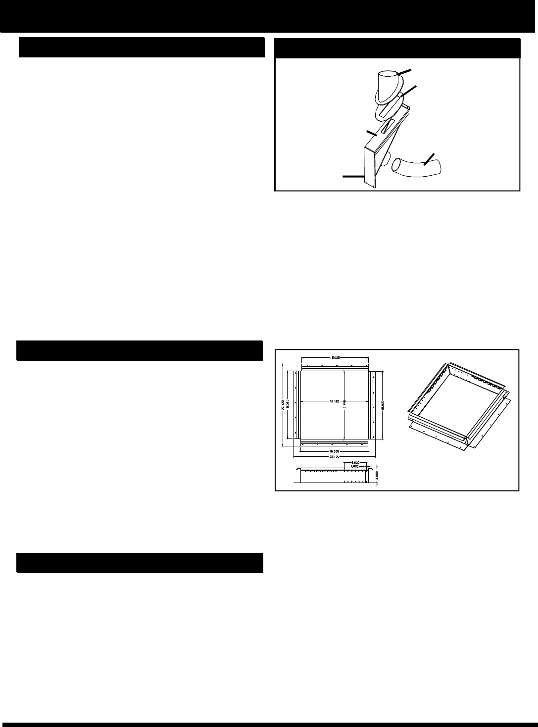
IMPORTANT: The mounting frame/surround
assembly and flue piping is the most critical part of
the installation and must be done correctly and installed
securely.
1. Choose the chimney configuration that is best suited
for the installation. See venting section.
• Note: If 100% outside air is desired or required, the
outside air option will need to be installed on the stoves
body. (See instructions included with outside air kit
(part #1-00-674080.) See Page 20.
2. Make sure the unit will fit into the fireplace opening.
See Fig # 17. When installing in smaller fireplaces,
test fit the mounting frame into the firebox. Note: The
unit overhangs to the rear.
3. Install the 3 piece cast surround set to the sides
and top of the mounting frame with the bolts and nuts
supplied. The left and right side should be done before
the center section is installed. Make sure the bolts
are loose. Do not remove the side panel hinges. The
left and right side wings should be standing up aligned
with the side of the mounting frame and slid inward
towards the center. Note:The wings mount on the rear
side below the notch and on the front side above the
notch. See Fig. 16 & 18. Slide the cast ash lip onto
the frame and check to make sure it can go against
the roped frame rails and fits into the pockets on the
left and right cast sides. See Fig. 19.
Install the center section.
Beginning Installation 3" Outside Air
starter collar
NOTE: The stove body extends through the mounting frame
in the rear approximately 2".
Approximately 2" overhang
Fig. 16
Fig. 17
Notch
Cast in front of
the frame. Use
(1)1/4-20 x 3/8
flange bolt from
the rear.
Cast behind the
mounting frame
flange. Use (2)
1 / 4 - 2 0 x5 / 8
flange bolts and
nuts with bolts
from the front.
Fig. 18
Slide the ash lip
casting into the
frame, making
certain the ash lip
is sitting on the
slide rails on
either side. With
the ash lip in
place, adjust the
surround sides so
there is an even
gap where the ash
lip extends into the
surround side and
tighten. Fig. 19
Ash lip slide rails
4. If the wing extensions are required they should be
installed next.
Evaluation notes were added to the output document. To get rid of these notes, please order your copy of ePrint IV now.
12
Installation
5. The power cord can be installed exiting the left
(standard) or right side of the surround. If a right side
cord is desired, follow the instructions below.
Changing the cord exit location from the left side
to the right side:
The cord is located on the left side, standard from
Harman. (See fig 21.)
To route the cord to the right side:
• Cut the tyraps looping the cord to the left
• Reroute the cord along the top of the steel angle and
down the right side.
• Re-tyrap (not supplied by Harman) the wire through
the notches provided in the mounting frame. Then down
the right side rail.
• Do not remove or move the cord retainer, it is made
to reach both the right and left sides.
Nothing can ex-
tend beyond this
face to the back
side. DO
NOT
CUT.
Connecting the cord retainer to the wing
With the three wing pieces completed, the cord re-
tainer must be bolted to the bottom rear of the wing.
Either left exit (shown in fig. 22) or right exit.
At the bottom rear edge of the right and left wing there
is a small radius indent for the cord to exit between
the wing and the fireplace face.
6. You must now decide whether to install the room
sensor as a wall sensor or as a return air sensor.
Harman highly recommends that the room sensor be
installed. If you are installing the room sensor as a wall
sensor, the long black 2 wire cable must be Ty-rapped
to the powercord. This wire is long enough to reach the
end of the power cord so the installer can reach past
the hearth to the location where the extension wire (18/
2 thermostat wire, not supplied by Harman) can be
spliced to go to the wall location chosen for the room
sensor.
Ground
Ty-raps
Fig. 21
Fig. 22
Fig. 23
Optional Wing Extensions
Optional wing extensions are made for fireplace open-
ings which are larger than the cast wing. The 3 piece
wing extension is 48" wide by 34"high.
Custom oversized wing extensions can be purchased
from Harman for any fireplace openings larger than the
standard wing extension area.
These optional wing extensions will have a 1/2 inch re-
turn bend as shown in fig. 20. Custom oversized wing
extensions with a radius top can be ordered with a ra-
dius of your choosing. These radius top wings WILL
NOT have a return bend, although they will be made of
thicker metal to reduce warpage.
Fig. 20
1/4-20 x 3/8
bottom head bolts
(5/32" allen wrench)
(5/32" allen wrench)
Evaluation notes were added to the output document. To get rid of these notes, please order your copy of ePrint IV now.
13
Installation
7. If the room sensor is used as a return air sensor
rather than a room thermostat/sensor, the black cable
will not be used. The room sensor itself (gray cable
with black and red wires) will be connected to the blue
twisted wires from the control board.
Note: The stove body must be able to slide out of the
shell to the limit of the power cord wires for cleaning
and service. Therefore, if the room sensor is connected
as a return air sensor, the wire should be connected
long enough to allow this, but not too long that it would
get tangled or pinched anywhere.
Notice: The male/female connections between the
mounting shell and the stove body should always be
maintained. Wirenut or taped splices should never be
used.
Connecting the room sensor as a return air sensor
• Insert the sensor end of the wire from the rear of the
mounting frame through the hole as shown in fig. 24 .
• Tyrap the sensor end so that the sensing tip is in the
middle of the front return air opening. See Fig. 25.
• Tyrap the sensor wire to the inside of the mounting
frame up to the cord grounding location. Follow the
power wiring to where you make the male/female ter-
minal connection to the twisted blue wires.
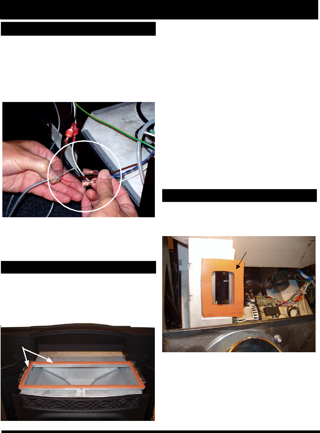
There are (2) crimp-on connectors in the hardware pack
that must be installed on the internal ends of the room
sensor wires.
Side Return Air Holes
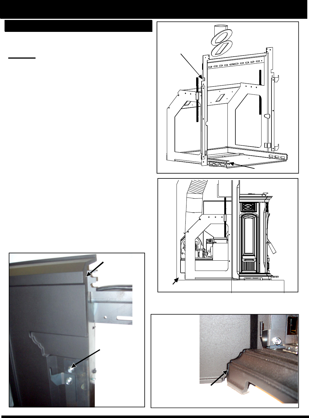
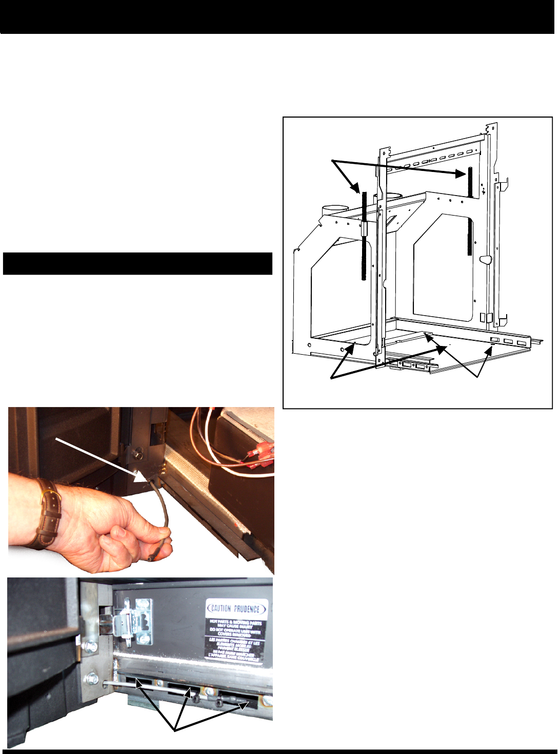
8. Install the (4) 3/8-16 x 1" leveling bolts into the
threaded holes in the bottom pan of the mounting shell.
The front two leveing bolts may not be necessary, but
the back two will need to be used to level the wing so
that it is flush with the fireplace face. See Fig. 26.
R3
Fig. 24
Fig. 25
3/8 x 16 tapped
leveling bolt holes
Fig. 26
1/2" threaded
wedging rods
(5) bolt down holes
Evaluation notes were added to the output document. To get rid of these notes, please order your copy of ePrint IV now.
14
9. Install the completed frame/surround assembly into the
firebox and level/plumb the wing to the fireplace face using the
leveling bolts as jacks.
* Ash protection must be used from hearth opening to 6" in
front of door glass and 6" to each side of the stove body to
protect any combustibles from hot ashes. A minimum size
will be 16.5" deep by 30" wide and be made of a non-
combustible material or meet UL approval.
10. Test fit the cast ash lip (See fig. 25) on the shell frame
mounting rails. The ash lip should slide on these side rails
without lifting upward off of the rails as the ash lip is slid inward.
A small clearance of about 1/16" is an ideal space between the
legs of the ash lip and the hearth. This cast ash lip is a decorative
part that does not and should not support any weight.
11. Tighten the (2) 1/2" threaded wedging rods up against the
lintel of the fireplace opening. It is also recommended to use
some form of anchoring screws through the bottom of the shell
into the hearth. There are up to 5 holes provided. Note: It is a
good idea to check the ash lip again. The frame may have
shifted when the final anchoring was completed. See fig. 26.
12. Complete the flue piping, and outside air piping, if used.
Make sure the damper area is sealed.
CAUTION: IF THE STAINLESS STEEL FLUE PIPE DOES
NOT EXTEND FAR ENOUGH ABOVE THE OLD DAMPER
OPENING, MAKE SURE THE FIBERGLASS INSULATION
DOES NOT EXTEND UPWARD AND COVER THE PIPE
OUTLET.
WARNING DO NOT CONNECT THIS UNIT TO ANY AIR DIS-
TRIBUTION DUCT OR SYSTEM.
13. If a rear exit flue configuration is used, with or without outside
air, make sure the flue pipe termination clearances are followed
as per the manufacturers recommendations.
16. Place the stove body on the mounting shell gasketed
rails and insert the body into the opening far enough that
it can't tip out. Note: A service rail kit (part # 1-00-08007),
or a pair of 2x4's supported in front of the hearth will make
this job easier.' See Fig. 31.
17. Complete the following electrical connections (Caution:
Disconnect the power cord.) There are 5 connections that
must be completed. See Fig. 33 & 34.
Installation
Flue Pipe Stub Assembly
There are three different diameter flue pipe stub
assemblys.
1. The unit comes standard with the largest for use with 4”
stainless steel flex pipe.
2. Part #1-10-082745 for use with 4” PL vent starter pipe.
3. Part # 1-10-674039 for use with 3” PL vent starter
pipe and also for use with 3” aluminum flex duct for out-
side air connections.
The flue stub assembly base is a round plate which al-
lows it to swivel to allow the flue pipe to exit the mount-
ing frame in other positions rather than straight up. See
fig. 28.
Fig. 28
Pre-cut ceramic insulation and (2) pieces of tie wire.
Fig. 27
Ash lip
mounting
rails
Twisted tie wire
With larger flue pipes this bottom edge of the insulation will
need to be trimmed to complete the wrap.
This picture shows the completed
insulation wrapped around the flue pipe
from the mounting frame upward.
Fig. 29
14. Install the flue pipe insulation wrap. See Fig. 27. This
ceramic insulation is precut to form around the flue pipe
stub, to reduce heat transfer into the area around the
rear of the hopper and motor area. This insulation must
be installed in all configurations, even if a rear
discharge is used. See Fig. 29.
(from glass)
Evaluation notes were added to the output document. To get rid of these notes, please order your copy of ePrint IV now.

15
Installation
Connecting the ground from the wing to the
stove body
• The green wire with a female terminal is the stove
body ground.
• On the combustion air inlet box there is a male ter-
minal ground.
• If service is performed on this stove, this ground
connection must be the first one on and the last
one off.
Fig.31
Fig. 32
Fig. 33
15. Install the cast side panels by sliding them down
over the lasered hinge pin. Note: Check for rotational
swing, but finish with them in the open position. The
cast side panels may need adjustment after the stove
body is latched into place and the front door is closed.
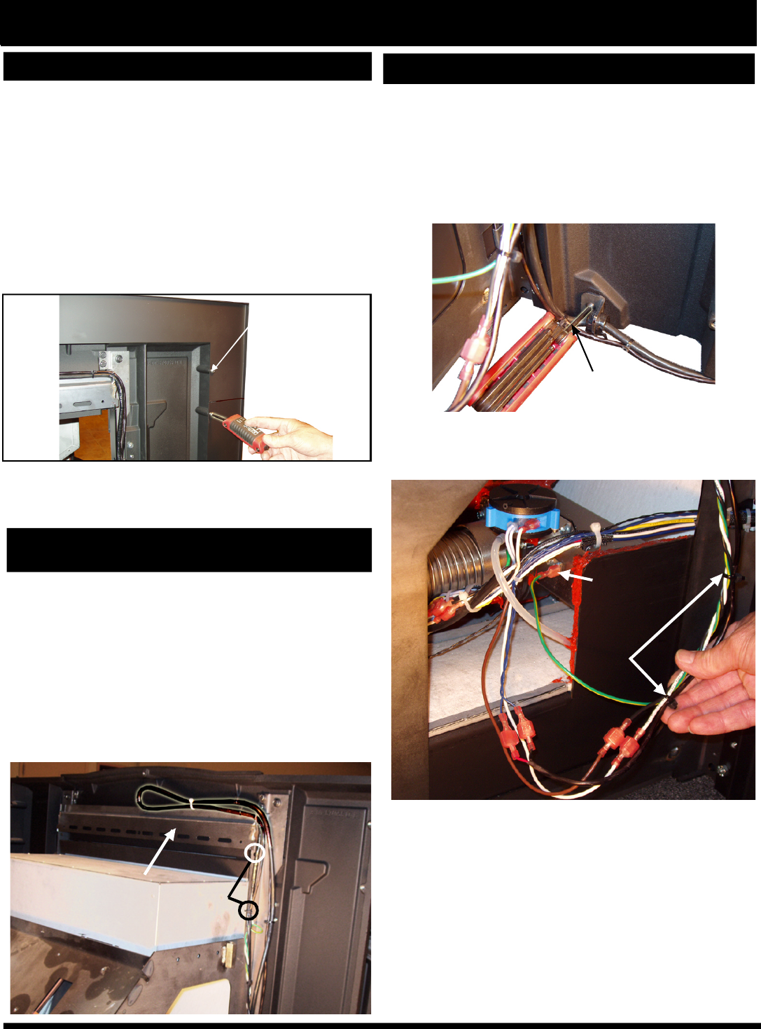
Connecting the power cord
The white from the mounting frame connects to the
white of the insert body.The black from the mounting
frame connects to the brown of the insert body.
2 x 4
Lasered hinge pin pivoting point
Up and down clearance adjustment slots.
Cast side
panel hinge
Fig. 30
16. Place the stove body on the mounting shell gasketed
rails and insert the body into the opening far enough
that it can't tip out. Note: A service rail kit (Part #1-00-
08007), or a pair of 2 x 4's supported in front of the hearth
will make this job easier. See Fig. 31.
17. Complete the following electrical connections
(caution: Disconnect the power cord.) There are 5
connections that must be completed. See Fig. 33 & 34.
Evaluation notes were added to the output document. To get rid of these notes, please order your copy of ePrint IV now.
16
Installation
Connecting the Room Sensor
Connecting the room sensor to the blue twisted wires
from the control board:
• (2) 3/16 inch male terminals are provided for the ends
of the room sensor wires.
• They will mate with the female terminals on the blue
twisted wires.
•These connections are “not polarity specific.”
Hopper Seal
Inspect the silicone sponge hopper to top seal gasket.
Look for tears or areas where the gasket may not seal
properly to the bottom of the cast top. This only needs
to be done when the top is removed. This is NOT nec-
essary if the cast top is not removed. (Not part of any
monthly, semi-annual or annual maintenance.)
Fig. 34
Fig. 35
Docking Gasket
Everytime the unit is pulled out of the mounting frame,
the orange high temperature docking gasket should be
inspected. Check for tears or signs that the gasket is
not sealing properly.
Fig. 36
19. Inspect the silicone sponge gasket on the top edge
of the hopper.
• If it is okay, put the cast top/hopper lid assembly (see
Fig. 35) into place over the hopper.
• Make sure the hopper lid is open to install unit, then
close it to keep from getting pinched in case the lid falls
unexpectedly.
• Insert the (4) 1/4-20 x 1/2 flange head bolts into the
mounting hole but do not tighten them.See page 8, fig.
12.
20. "Test" the unit with the stove body pulled out. This
will allow you to see the motors in operation.
• Turn the control to the "OFF" position.
• Plug the unit into a 120 VAC 60 hz outlet.
• Turn the control to "test". All of the motors should
operate at full voltage for 60 seconds.
Note: The door must be closed for the feed motor to
operate.
• With the "Test" completed, unplug the unit.
21. Inspect the flue docking gasket. See Fig. 36.
Hopper seal gasket (gray or orange)
18. Install the front door. Check the latch and gasketing.
Docking Gasket
Evaluation notes were added to the output document. To get rid of these notes, please order your copy of ePrint IV now.
17
Installation
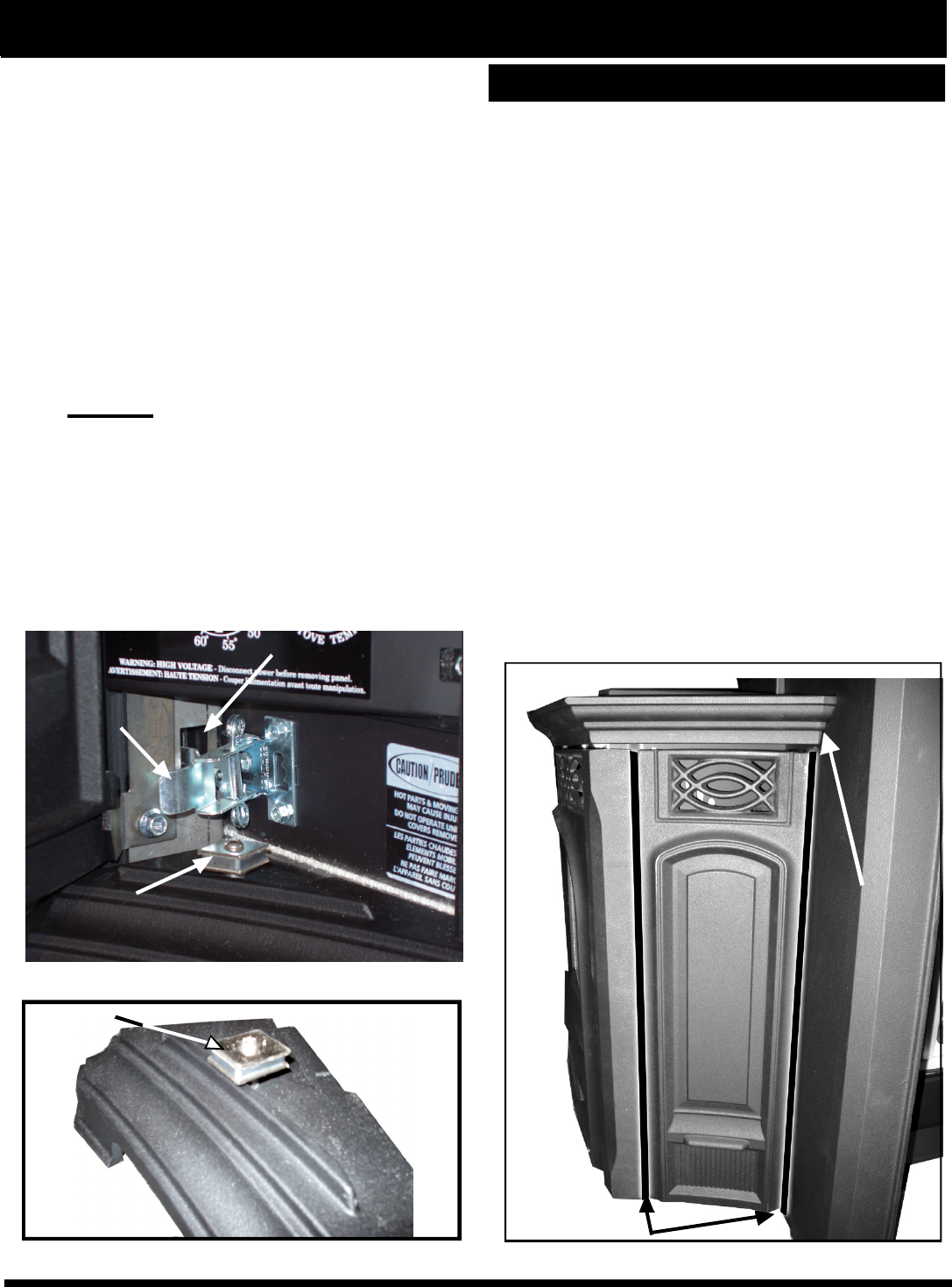
Cast Side Panel Installation
• The stove body must be pulled out of the mounting
frame several inches to install the cast side panels.
• Slide the cast side panel down over the hinge pins.
• Slide the stove body in and latch into place.
• Note: The cast side panels must be left in the open
position to allow access to the latches.
• Slide the ash lip into place. (This would be inward
until the rear of the cast iron touches the mounting
frame front.)
• Close the cast side panels.
• Check the gap alignment and the top and bottom
gap spacing.
• The top and bottom spacing can be adjusted by loos-
ening the 3 bolts and sliding the hinge up or down
until the spacing suits.
• With the front door closed and latched, check the
vertical space alignment. The only method of chang-
ing or adjusting this gap is by bending (slightly) the
hinge angle. See fig. 39.
• Due to the use of all cast iron parts, some small
amounts of misalignment are expected. Since some
parts are angled and some have rounded edges, this
misalignment is very seldom noticable.
• It is very important that the cast side panels open
and close freely for good control board access.
22. Slide the stove body into the mounting frame.
• Note: The two spring latches on the bottom
right and left side of the body must be in the proper
position to enter the latch holes. (See fig. 37).
• Latch the (2) spring latches into place.
23. Shift the cast top/hopper lid assembly inward as far
as possible to achieve a parallel fit with the surround
sides. See Fig. 39. Tighten the cast top/hopper lid
assembly bolts with a 3/8" socket. See page 8, Fig. 12.
24.Install and adjust the side panel magnets.
• In the hardware pack are (2) magnets, (2) spacers and
(2) 10-32 x 1 1/4" bolts and nuts.
• Bolt the magnets through the cast iron hole provided.
Important: The spacer must be on top of the
hole, the magnet on top of the spacer with the
bolt going down through the hole with the nut at
the bottom, under the ash lip. See fig. 38.
25. Check the fit of the cast ash lip to make sure that it
can be slid in and out easily. The cast ash lip can remain
in place at this time. Note: The cast side panel hinges
can be moved upward if necessary to gain clearance for
the cast ash lip.
Fig. 37
Fig. 38
Spring Latch
Latch Hole
Magnet
Magnet
Fig. 39
Fit cast
top/
hopper
lid
parallel
with
surround.
Side panel gap
Fit cast
top/
hopper
lid
parallel
with
surround.
Evaluation notes were added to the output document. To get rid of these notes, please order your copy of ePrint IV now.
18
Wiring
Always disconnect the power cord before the unit
is pulled from the mounting frame.
As you can see, the control board is easily accessible
from the rear with the body pulled out of the frame,
even if it is only pulled out several inches.
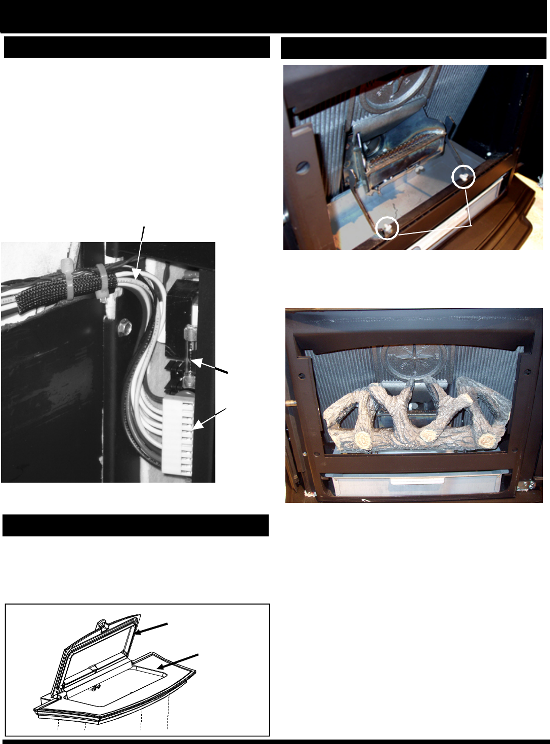
• Always inspect the wiring harness of the 11 pin sock-
ets (large white flat plug where all of the power wires
terminate.)
• Always inspect the wiring harness where the wires
transfer from the control to the rear inside of the body.
• Make sure there are no worn or frayed areas.
Installation
Inspect the wiring harness transition area: This is the area
that comes closest to the mounting frame as the unit is slid
in and out of the frame.
11 pin
socket
on rear
of control
board
6 amp
glass
fuse
Fig. 40
Hopper lid foam
gaskets
Cast Top
Fig. 41
Log Set Option
Fig.42
Fig. 43
Install the log bracket with the two thumb screws
provided.
Center the log in the firebox opening with the bottom
front edge over the thumb screws. The log branch
tips only rest on the bracket arms for easy installa-
tion and removal.
IMPORTANT NOTE: BEFORE CLEANING THE
HEAT EXCHANGERS, THE LOG AND THE
LOG BRACKET MUST BE REMOVED.
REMINDERS
• Do not allow pellets or sawdust to build up on the
hopper lip.
• Inspect the hopper lid gasket for damage. A good
hopper lid seal is very important for proper opera-
tion.
Thumb
Screws
Evaluation notes were added to the output document. To get rid of these notes, please order your copy of ePrint IV now.
19
These units are pre-tested at the factory with
exactly 120 Volts A.C., 60 Hz. They are checked and
adjusted for firebox tightness, gasket leakage, motor
operation and igniter operation. The stove is then
factory set at a high adjustment. NOTE: Low draft
adjustment may be required. The factory low draft
setting may not be correct for the units permanent
installation conditions.
The control board on the Accentra Insert is
equipped with a low draft adjustment port. Located
on the control face just to the right of the igniter light.
See Figure 44. This voltage adjustment is provided to
allow the unit to be adjusted for the household voltage
where the unit is going to be in permanant operation.
NOTE: The line voltage varies from area to area and
often home to home.
The low draft voltage should be adjusted to
achieve the most efficient burn on low burn or
"maintenance". This voltage adjustment allows the
installer to change the low voltage set point
approximately 15 volts. This adjustment should be
done by the installer during set up because a draft
meter reading is required to insure proper set up.
If the unit is not adjusted properly, it does not
cause a safety concern. If the unit is adjusted too high,
only effiency is lost. If the unit is adjusted too low, the
low draft pressure switch will not allow the feeder
motor or the igniter to operate.
After the installation is completed but before the first fire is lit,
check and record the high and low draft readings.
A simple draft test should be performed after
completing the flue pipe installation. To record the
results for future reference:
1. Plug unit into a 120VAC, 60 HZ outlet.
2. Close the hopper lid and front view door. Neither
pellets or a fire are required for this test.
3. With the mode selector in the "OFF" position, turn
the feed adjuster to "TEST".
4. Record the high draft_____in. W.C. (Normal is -
.45 to -.55) The control will be on the High Draft for a
total of 2 minutes.
5. After 2 minutes is up, the combustion motor will
go down to low draft and the distribution blower will
go on high. Allow approximately 15 seconds to pass
for the combustion motor to slow before checking the
low draft.
6. If the low draft is between .30 and .35, record the
reading _____ in. W.C. If the reading is higher, slowly
turn the set screw counter-clockwise until the draft
lowers. If the reading is lower, very slowly turn the set
screw clockwise until the draft increases.
NOTE: The test mode alternates from high to low
draft every 60 seconds. If more time is needed
for draft adjustment, wait until the next low draft
cycle.
NOTE: In some cases, the draft may not go as
low as .30 even with the set screw completely
counter-clockwise.
Combustion
Motor Speed
Control
Low draft only
set point.
The small
straight
screwdriver slot
is plastic;
therefore, the
unit can be
adjusted while
in operation.
Fig.44
Low Draft Voltage Adjustment
Draft Meter bolt hole location
The head of the plug bolt can be accessed through
the bottom distribution air inlet with the cast ash lip
removed.
Fig. 45
Evaluation notes were added to the output document. To get rid of these notes, please order your copy of ePrint IV now.

20
Mobile Home Installation
CAUTION
THE STOVE IS HOT WHILE IN OPERATION.
KEEP CHILDREN, CLOTHING AND
FURNITURE AWAY. CONTACT MAY CAUSE
SKIN BURNS.
KEEP COMBUSTIBLE MATERIALS SUCH
AS GRASS, LEAVES, ETC. AT LEAST 3 FEET
AWAY FROM THE POINT DIRECTLY UNDER
THE VENT TERMINATION.
WARNING
When installing and operating your Harman
Accentra Insert, respect basic safety standards.
Read these instructions carefully before you attempt
to install or operate the Accentra Insert. Failure to
do so may result in damage to property or personal
injury and may void the product warranty.
Consult with your local building code agency
and insurance representative before you begin your
installation to ensure compliance with local codes,
including the need for permits and follow-up inspec-
tions.
CAUTION: This appliance must be vented
to the outside.
Due to high temperatures, this stove should
be placed out of traffic and away from furniture and
draperies.
Children and adults should be alerted to the
hazards of high surface temperatures and should
stay away to avoid burn to skin and/or clothing.
Young children should be carefully supervised
when they are in the same room as the stove.
Clothing and other flammable materials should
not be placed on or near this stove.
Installation and repair of this stove should be
done by a qualified service person. The appliance
should be inspected before use and at least annu-
ally by a qualified service person. More frequent
cleaning will be required. It is imperative that control
compartments, burners, and circulating air pas-
sageways of this stove be kept clean.
Safety Reminders
Mobile Home Installation
Mobile home installation should be done in
accordance with the Manufactured Home and
Safety Standard (HUD), CFR 3280, Part 24.
When installing the Accentra in a mobile home
several requirements must be followed:
1. The unit must be bolted to the floor. This can
be done with 1/4" lag screws through the 5 holes in
the base plate shown in Fig. 26.
2. The unit must also be connected for the out-
s ide a ir. S e e pa ge 2 1 .All mo bile ho me ins ta lla tions
re quire the us e o f o uts ide a ir, th is will inc re a s e the
he a ting e ffic ie nc y of the unit a nd ke e p it from s uffe r-
ing a ny e ffe cts a s s o c ia te d with ro o m a ir s ta rva tio n
s uc h a s p o o r c o m bus tion a nd o r e rra tic o p e ra tio n.
P e rio dic a lly c he c k the a ir inle t fo r a ny o bs truc tio ns
s uc h a s s no w o r ic e bu ild up.
Kitc h e n e xha us t fa n s , c lo the s dr ye rs a n d
o the r s imila r de vic e s m a y c a us e im pro pe r o pe ra tio n
o f the pe lle t s to ve , if, while in us e it ke e ps the ro o m in
a ne ga tive pre s s ure thus a llo wing pipe jo ints no t c o m-
ple te ly s e a le d to le a k e xha us t into the roo m . Be s ure
to a llo w a de qua te ve ntila tio n while us ing s uc h a ppli-
ances
3 . F lo o r p r o t e c tio n a n d c le a r a n c e s m u s t b e
fo llo we d.F lo o r pro te c tio n a nd c le a ra nc e s to c o mbus -
tible s mus t be fo llo we d a s pe r ins ta lla tio n ins truc tio ns
fo r the s to ve . C le a ra nc e s ma y o nly be re duc e d by
me a ns a ppro ve d by the re gula to ry a utho rity.
4 . Unit mus t be grounde d to the m e ta l fra m e o f the
mo b ile ho me .
5 . S m o ke a la rms a nd s m o ke de te cto rs a re re co m -
me nde d to be us e d with wo o d a nd bioma s s fue le d
s to ve s . W he n o pe ning the fire bo x do o r s o m e e x-
ha us t ma y e s c a pe into the ro o m a nd s et o ff the a la rm .
If this s ho uld ha ppe n ve ntila te the ro o m to re mo ve
the s mo ke a nd re s e t the a la rm , if the a la rm wo uld go
o ff whe n no o ne wa s wo rking with the s to ve ve ntila te
the ro o m a nd ha ve yo ur ho me c he c ke d to find the
s o urc e o f the le a k.
CAUTION
THE STRUCTURAL INTEGRITY OF THE
MOBILE HOME FLOOR, WALL, AND CEILING/
ROOF MUST BE MAINTAINED.
WARNING
USE OF IMPROPER FUELS, FIRE STARTERS
OR ALTERING THE STOVE FOR HIGHER HEAT
OUTPUT MAY CAUSE DAMAGE TO THE STOVE
AND COULD RESULT IN A HOUSE FIRE. USE
ONLY APPROVED FUELS AND OPERATION
GUIDELINES WARNING
DO NOT INSTALL THIS UNIT IN ANY
SLEEPING ROOM
Evaluation notes were added to the output document. To get rid of these notes, please order your copy of ePrint IV now.
21
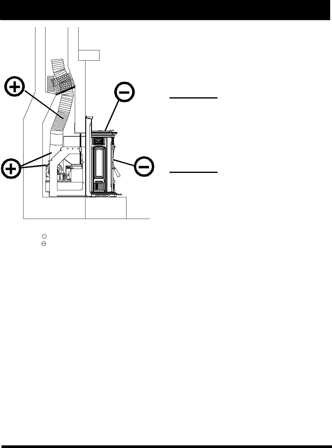
A combustion blower is used to extract the com-
bustion gases from the firebox. This causes a negative
pressure in the firebox and a positive pressure in the
venting system as shown in fig. 46. The longer the vent
pipe and more elbows used in the system, the greater
the flow resistance.
The recommended maximum flue lengths for the
Accentra Insert are as follows:
4" Stainless Steel Flex: 30 Lineal ft. Vertical*
4" PL Vent Pipe:
4" Pl Vent Pipe: 30 Lineal ft. Vertical*
4" Pl Vent Pipe: 14 ft. Vertical w/1-90o and 12 lineal ft. horizontal*
If additional 4" PL Vent fittings are required, the overall
length must be reduced by:
Vertical 90o or T: 2.5'
Vertical 45o
: 1.5'
Horizontal 90o or T: 5.0'
Horizontal 45o
: 2.5'
3" PL Vent Pipe:
20 Lineal ft. vertical*
8 Lineal ft. vertical w/1-90o & 8 lineal ft. horizontal*
If additional 3" PL Vent fittings are required, the overall
length must be reduced by:
Vertical 90o or T: 2.0'
Vertical 45o
: 1.0'
Horizontal 90o or T: 4.0'
Horizontal 45o
: 2.0'
* Long runs of flex or PL vent pipe installed directly vertical from the flue stub
may require more frequent cleaning due to fly ash falling off inside and
collecting directly above the combustion blower outlet.
Any use of horizontal venting will require more frequent cleaning. It is the
responsibility of the installer to make sure all flue configuration are accessible
for cleaning.
4" stainless steel flex vent piping is only allowed
for use in masonry fireplaces and chimneys or factory
built wood burning fireplaces with class A metal chim-
neys. All pellet vent pipe whether flex type, PL or an-
other approved type must be secured together either
by means provided by pipe manufacturer or by 3 screws
at each joint.
DO NOT INSTALL A FLUE DAMPER IN THE
EXHAUST VENTING SYSTEM OF THIS UNIT.
DO NOT CONNECT THIS UNIT TO A CHIMNEY
FLUE SERVING ANOTHER APPLAINCE.
Venting
+ = Positive static pressure
= Negative static pressure
Fig.46
Inside hopper
Inside
firebox
In flue pipe
In fan
chamber
&
starter
collar
Evaluation notes were added to the output document. To get rid of these notes, please order your copy of ePrint IV now.
22
Outside Air
Outside air is optional (not required) except in
mobile homes and where building codes require it
to be installed. The benefit of outside air is mainly
noticed in small, very tight houses.
The outside air kit consists of a flue stub pipe,
fiberglass gasket, silicone gasket, intake box and a
section of flex pipe. See Fig. 47.
An adjustable chimney intake extension, part #
1-00-674104 is available to be used on masonry
chimneys only. See Fig. 48.
Additional information and diagrams can be
found on pages 22 thru 26 under venting.
To install outside air, use kit part number 1-10-
674080. Follow the installation instructions provided
with the kit.
HRV
When installing in a house with a Heat Reclaim-
ing Ventilation System (HRV) be sure the system is
balanced and is not creating a negative pressure in
the house.
If the Accentra Insert is installed with the 100%
outside air kit, the HRV should not have to be ad-
justed.
Vent Pipe
Be sure to use approved pellet vent pipe
wall and ceiling pass- through fittings to go
through combustible walls and ceilings. Be sure
to use a starting collar to attach the venting sys-
tem to the stove. The starting collar must be
sealed to the vent pipe with high temp silicone
caulking.
4" stainless steel flex vent piping is only
allowed for use in masonary fireplaces and chim-
neys or factory built woodburning fireplaces with
class A metal chimneys.
Pellet venting pipe ( also known as PL vent
) is constructed of two layers with air space be-
tween the layers. This air space acts as an insu-
lator and reduces the outside surface tempera-
ture to allow a clearance to combustibles of only
3 inches. The sections of pipe lock together to
form an air tight seal in most cases; however, in
some cases a perfect seal is not achieved. For
this reason and the fact that the Accentra Insert
operates with a positive vent pressure, we
specify that the joints also be sealed with clear
silicone.
Venting
Fig. 47
Fig. 48
Adjustable Chimney
Intake Extension
Part # 1-00-674104
100% Outside Air Kit
100% Outside Air
Kit # 1-00-674080
Designed for 3" flex pipe
1/8" Fiberglass Gasket
2 3/8" ID Flex Pipe
1/2" Silicone Gasket
Intake Box
Evaluation notes were added to the output document. To get rid of these notes, please order your copy of ePrint IV now.
23
Venting
Fig. 50
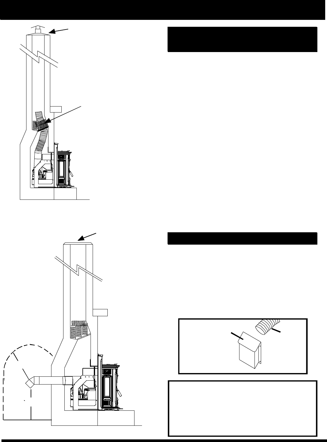
This method provides excellent venting for nor-
mal operation. This method also provides natural
draft in the event of a power failure.
The damper area must be sealed with a steel
plate or fiberglass. A cap should be installed on the
chimney to keep out rain.
Combustion air is provided from the living area
and enters the feed system from around the wing
and stove body spaces.
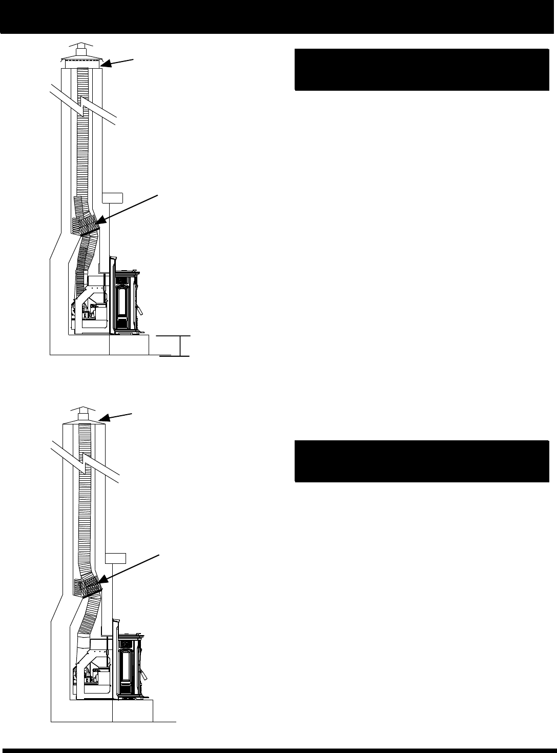
#2 Installing into an existing
fireplace chimney (US & Canada)
This method provides excellent venting with
100% outside air which is the most efficient opera-
tion of this unit. This method also provides natural
draft in the event of a power failure.
A 4 inch stainless steel flex pipe is needed for
the flue pipe, and 3" aluminum or Stainless Steel Flex
Pipe is used for the intake.
In Canada and some places in the US it is re-
quired that the vent pipe extend all the way to the top
of the chimney.
#1 Installing into an existing fireplace
chimney (US & Canada)
Fig. 49
Height of existing hearth
Fiberglass insulation
packed above the
damper opening and
sealed plate. (Not a
Harman product.)
Fiberglass insulation
packed above the
damper opening and
sealed plate. (Not a
Harman product.)
The chimney top must be capped
to prevent rain and/or snow from
entering the chimney.
See Page 21. for information on
the optional Harman Adjustable
Stainless Steel Intake Extension.
The chimney top must be
capped to prevent rain and/or
snow from entering the chimney.
Evaluation notes were added to the output document. To get rid of these notes, please order your copy of ePrint IV now.
24
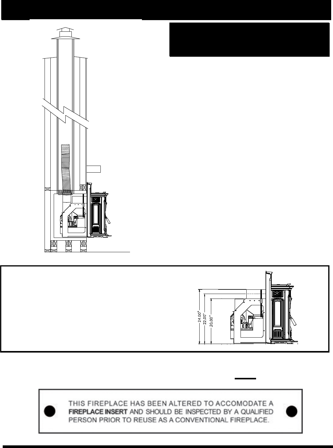
This method provides excellent venting for nor-
mal operation. This method also provides natural
draft in the event of a power failure. If the chimney
condition is questionable you may want to install a
liner as in method #2.
This is the minimum allowed vent pipe using 4"
stainless steel flex pipe.
The vent pipe must extend past the damper
sealing area by at least 12 inches.
Note: The fiberglass insulation must not be al-
lowed to expand to the point that it covers the end of
the flex pipe.
The chimney should be capped with any style
cap that will not allow rain or snow to enter.
Fig.51
Venting
#3 Installing into an existing
chimney (US only)
#4 Preferred method
This method provides excellent venting for nor-
mal operation and in a fireplace with inadaquate flue
space, or a height of over 30 feet. A 3" or 4" PL vent
pipe should be used with an optional swivel flue stub.
NOTE: The flue stub insulation wrap must still
be used with this method. See page 13, Fig. 27 &
29. With a 100% outside air kit the outside air can
be installed in the same manner as the flue pipe.
Fiberglass insulation
packed above the
damper opening and
sealed plate. (Not a
Harman product.)
KEEP COMBUSTIBLES (SUCH AS
GRASS, LEAVES, ETC.) AT LEAST 3
FEET AWAY FROM THE FLUE OUTLET
ON THE OUTSIDE OF THE BUILDING.
CAUTION
The chimney top must be
capped to prevent rain and/or
snow from entering the chimney.
Stainless Steel
Outside Air Inlet
Cover
part# 1-10-09542
3" Flex
pipe
12" minimum
Fig.52
18" min.
36"
Fiberglass insulation
packed above the
damper opening and
sealed plate. (Not a
Harman product.)
Chimney top
MUST BE SEALED
Evaluation notes were added to the output document. To get rid of these notes, please order your copy of ePrint IV now.
25
Installing the Accentra Insert into an
existing factory built wood burning
fireplace
When installing the Accentra Insert into a factory
built wood burning fireplace, several things need to be
taken into consideration.
The size of the fireplace opening. Will the unit fit
into the opening? Many of these units have metal
smoke shields inside the top that can be removed to
gain height. Often the side and rear refractory can be
removed to gain depth and width.
Some factory built fireplaces have a firebox that
is lower than the opening. Many have a bottom lip that
is higher than the hearth. This is an issue with the
Harman Accentra Insert since we do not have any-
thing to fill the space between the bottom of the unit
and the hearth. It would be the responsibility of the
installer to supply something to fill this space and be
strong enough to support the front of the insert.
As for the size and position of the existing chim-
ney and its damper system, the Harman Accentra In-
sert has a swivel style flue stub that will allow the stain-
less steel flex pipe to exit into most factory built fire-
places.
OPTIONAL HOPPER CONFIGURATIONS FOR
SMALLER FIREPLACE OPENINGS:
The Harman Accentra Insert can be factory built with
shorter hopper configurations.
The standard requires a 24" opening. Part #1-90-00674
Option 1: Requires a 22" opening height. Part #1-90-00675
Option 2: Requires a 20" opening height. Part #1-90-00676
Keep in mind the hopper capacities will decrease with the
optional heights.
Venting
Note: If the Harman Accentra Insert is installed into a factory built wood
burning fireplace, this label (Harman part # 3-90-00675) MUST be attached
to the altered fireplace.
Fig. 53
Fig. 54
Evaluation notes were added to the output document. To get rid of these notes, please order your copy of ePrint IV now.
26
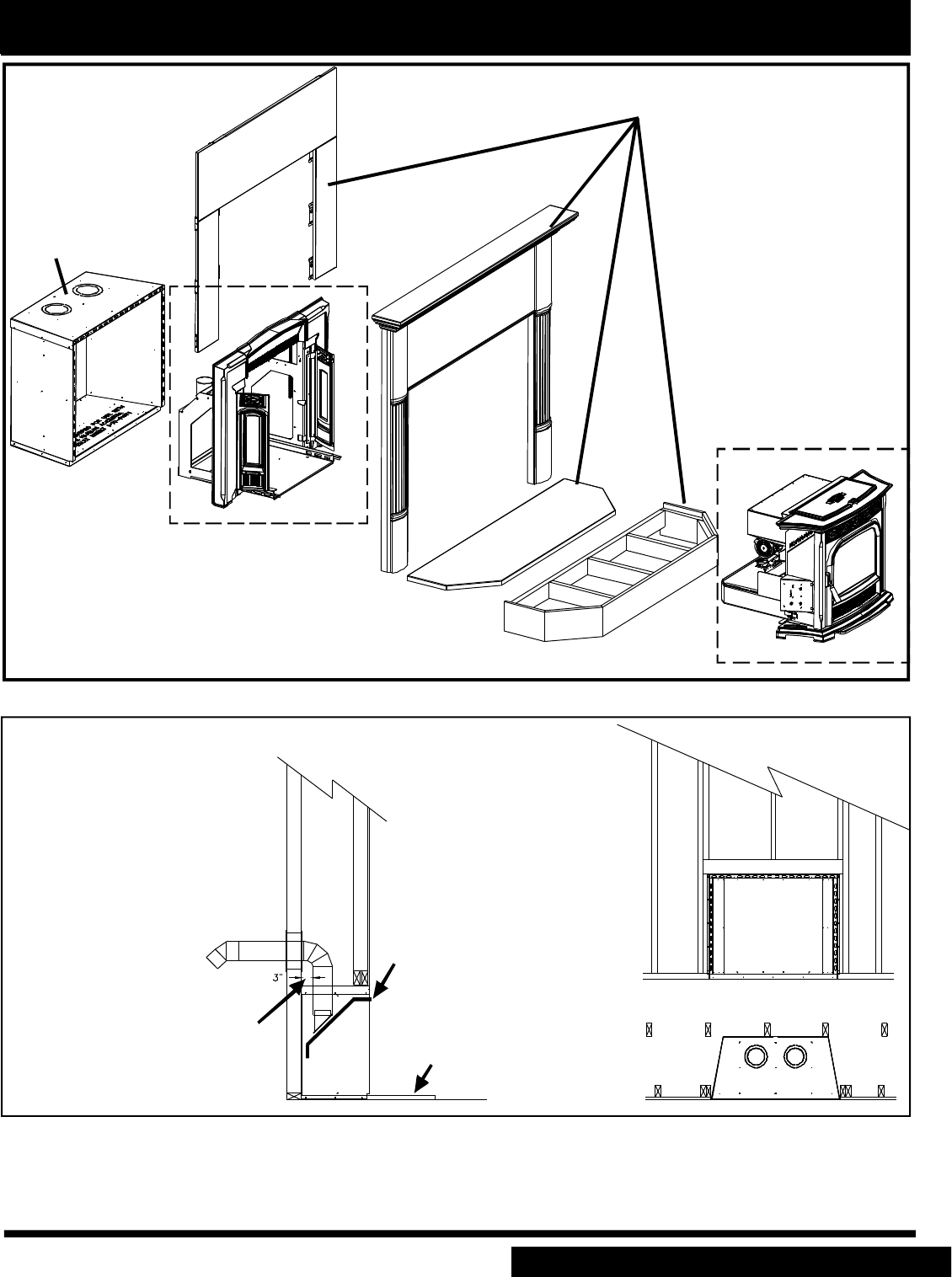
AFTER THE INSTALLATION IS COMPLETED
Harman Accentra Insert Zero Clearance Cabinet
See your dealer for part details
and installation instructions.
Harman Mantel System
Combustible materials are allowed to touch the cabinet anywhere behind the front mounting flanges except vent
clearance areas. The hearth substructure may be built of combustible material although a non-combustible hearth
surface (tile, stone, metal, glass) must extend as far as shown on the UL label.
Fig. 55
Fig. 56
Accentra Insert Zero Clearance Cabinet
Be sure to use ap-
proved pellet vent pipe wall
and ceiling pass- through
fittings to go through com-
bustible walls and ceilings.
Be sure to use a starting col-
lar to attach the venting sys-
tem to the flue stub and seal
the connection with high
temperature silicone.
Harman Zero
Clearance cabinet
(top flue only)
Part #1-00-674070
Insert Wing &
Mounting Frame
Insert Body
When using 3" or 4" PL vent
pipe, there must be a 3"
clearance to combustibles.
A minimum of a 1" hearth is
required when using the
Harman Zero Clearance box.
Harman Zero Clearance Box
Flue Pipe Support (optional)
Part # 1-00-674119
Evaluation notes were added to the output document. To get rid of these notes, please order your copy of ePrint IV now.
27
Venting
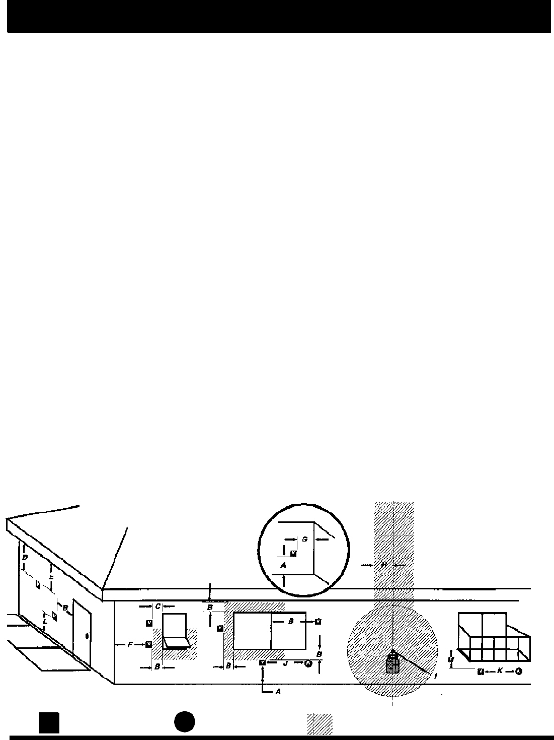
Requirements for Terminating the Venting
WARNING: Venting terminals must not be re-
cessed into a wall or siding.
NOTE: Only PL vent pipe wall pass-throughs
and fire stops should be used when venting through
combustible materials.
NOTE: Always take into consideration the ef-
fect the prevailing wind direction or other wind cur-
rents will cause with flyash and /or smoke when plac-
ing the termination.
In addition, the following must be observed:
A. The clearance above grade must be a mini-
mum of 18".1
B. The clearance to a window or door that may
be opened must be a minimum of 48" to the side
and 48" below the window/door, and 12" above the
window/door. 1
( with outside air installed, 18” )
C. A 12" clearance to a permanently closed win-
dow is recommended to prevent condensation on
the window.
D. The vertical clearance to a ventilated soffit
located above the terminal within a horizontal dis-
tance of 2 feet (60 cm) from the center-line of the
terminal must be a minimum of 18".
E. The clearance to an unventilated soffit must
be a minimum of 12".
F. The clearance to an outside corner is 11"
from center of pipe.
G. The clearance to an inside corner is 12".
H. A vent must not be installed within 3 feet (90
cm) above a gas meter/regulator assembly when
measured from the horizontal center-line of the regu-
lator.1
I. The clearance to service regulator vent outlet
must be a minimum of 6 feet.1
J. The clearance to a non-mechanical air sup-
ply inlet to the building or the combustion air inlet to
any other appliance must be a minimum of 48”.
1
K. The clearance to a mechanical air supply
inlet must be a minimum of 10 feet.1
(with outside air installed, 6 feet )
L. The clearance above a paved sidewalk or a
paved driveway located on public property must be
a minimum of 7 feet.1,2
M. The clearance under a veranda, porch, deck
or balcony must be a minimum of 12 inches.1,3
NOTE: The clearance to vegetation and other
exterior combustibles such as mulch is 36” as mea-
sured from the center of the outlet or cap. This 36”
radius continues to grade or a minimum of 7 feet
below the outlet.
1Certain Canadian and or Local codes or regu-
lations may require different clearances.
2A vent shall not terminate directly above a side-
walk or paved driveway which is located between
two single family dwellings and serves both dwell-
ings.3Only permitted if veranda, porch, deck, or bal-
cony is fully open on a minimum of 2 sides beneath
the floor.
NOTE: Where passage through a wall, or
partition of combustible construction is desired,
the installation shall conform to CAN/CSA-B365.
(if in Canada)
VA
= Vent terminal = Air supply inlet
Fixed
Closed
Openable
Openable Fixed
Closed
Inside
Corner
Detail
= Area where terminal is not permitted
Evaluation notes were added to the output document. To get rid of these notes, please order your copy of ePrint IV now.
28
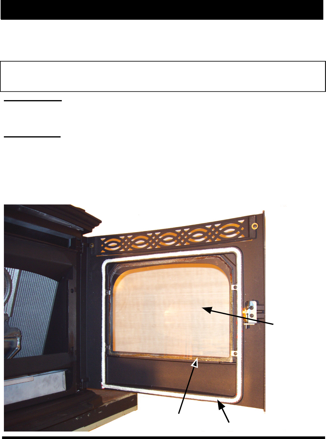
Maintenance - Cleaning Glass on View Door
The unit should be out and cool to clean the door glass. It may not always be possible to allow the unit to
cool off before cleaning. Therefore, if the unit is turned to the lowest setting about 1 hour before cleaning, it will
make it possible to clean the glass with the unit in operation.
Any glass cleaner with a high amonia content will work the best. Use only non-synthetic cleaning rags
such as cotton or paper towels.
CAUTION: Take care when spraying cleaner on the inside surface of the glass. The glass may be hot
enough to cause undesirable fumes to fill the area around the unit very rapidly. Gloves and eye
protection are recommended.
Disposal of ashes: Ashes should be placed in a metal container with a tight fitting lid. The closed container of
ashes should be placed on a non-combustible floor or on the ground, well away from all combustible materials,
pending final disposal. If the ashes are disposed of by burial in soil or otherwise locally dispersed, they should be
retained in the closed container until all cinders have thoroughly cooled.
Soot and fly ash: Formation and need for removal. The products of combustion contain small particles of fly
ash. The fly ash will collect in the exhaust venting system and will restrict the flow of the flue gases. Pellet fuels
have different ash contents depending on what type of wood has been used to make the pellets. We
recommend to clean the system after approximately 1 ton of pellets have been burned and judge from
that how often the stove should be cleaned, remember if you change pellets it may change how often
you have to clean your stove.
Incomplete combustion such as occurs during start up, shutdown, or improper operation of the heater
will lead to some soot formation, which will collect in the exhaust venting system. The exhaust vent should be
inspected at least once every year to determine if cleaning is necessary.
Glass Gasket
Replace glass
only with high
temperature
ceramic glass.
Inspect door gasket during
cleaning and inspection
Fig. 57
Evaluation notes were added to the output document. To get rid of these notes, please order your copy of ePrint IV now.
29
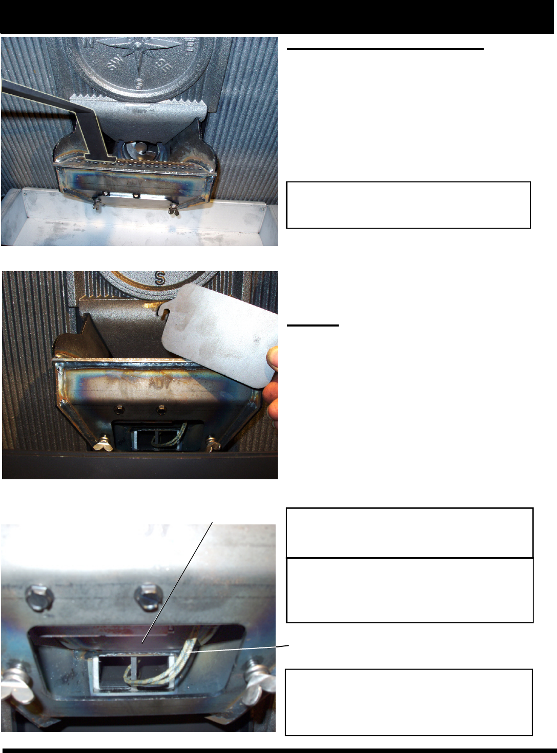
Burn Pot Cleaning and Maintenance
1. Scrape the top holed surface and sides of the
burn pot down to auger tube.(Fig 58) It is not
necessary to completely remove all material from
the burn pot. The excess will be pushed out during
the next use.
2. Loosen the (2) wing thumb screws on the lower
front angle of the burn pot. (Fig. 59)
3. Lift off the clean-out cover (Fig.59) to open the
bottom clean-out chamber. (Fig.60)
4. Clean ash buildup from inside the chamber while
cover is off. Use the scraper to tap on the top front
edge of the burn pot. This will help knock pieces of
ash, loosened by the scraping process, down
through the holes. It also helps knock scale off of
the igniter element.
Figure 60
The igniter is made to be removable for
service by insulated male/female wire connectors.
These connections between the hot leads (the
wires inside the burn pot) and the cold leads (the
wires from the control board) are always pulled to
the inside rear of the feeder body. (Not coiled
inside the burn pot.)
It is very important that these connections
are to the inside rear of the feeder body. Also, the
extra wire of the igniter wire service loop must be
pulled out through the rear of the feeder and tied
up so that it will not be damaged by any moving
parts.
WARNING
Use caution when cleaning burn pot clean-
out chamber. Do not damage the high
temperature igniter wires.
DANGER
Disconnect the power to the unit before
removing cover.
DANGER
Disconnect the power to the unit before
removing cover.
Igniter hot lead wires
(high temperature)
Viewed from below through the ash pan opening.
Note: The hot lead/cold lead connection
must always be pulled to the rear of the
feeder body before operation.
Maintenance - Burn Pot
Fig.58
Fig. 59
Fig. 60
Burn pot igniter
Evaluation notes were added to the output document. To get rid of these notes, please order your copy of ePrint IV now.
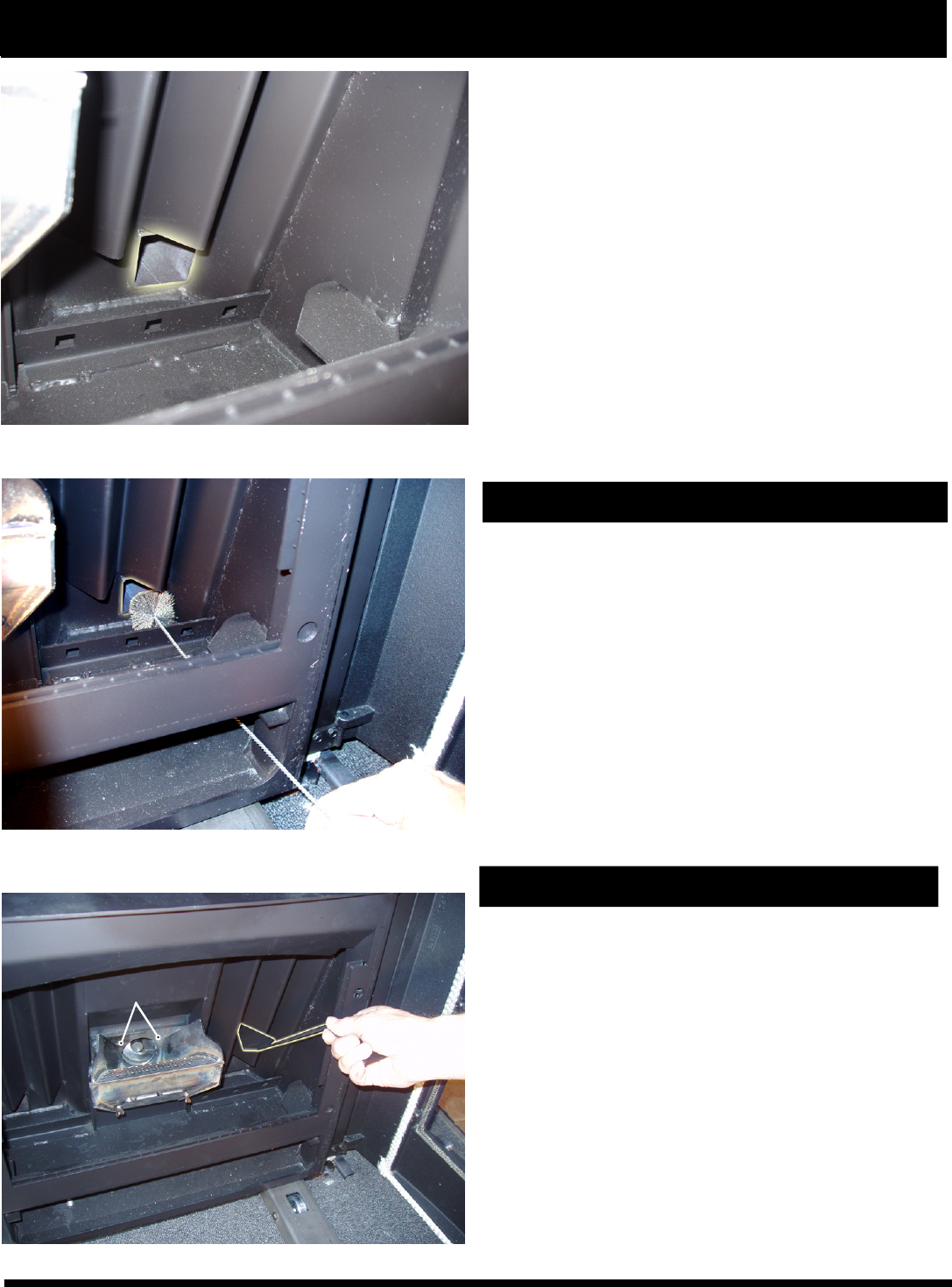
30
Maintenance - Cleaning
Cleaning the Heat Exchanger
The accordion heat exchanger surfaces are the pri-
mary source of heat transfer into the room. Therefore,
it is very important to keep them clean from flyash and
soot buildup.
• The heat exchanger surfaces should be cleaned af-
ter approximately every 1 ton of pellets are used.
• Use the scraper provided to clean all the way into the
point.
• Note: An old paint brush works well to clean these
surfaces.
• Note: The unit “must be cold” before using anything
other than a wire brush.
• There are 2 primary air inlet holes on the rear flange
of the burnpot. They should be checked for blockage
and cleaned with a vacuum if necessary. Note: The
bottom of the flame guide has 2 notches that match
the holes.
Cleaning the Heat Exchanger tubes
Using the cleaning brush provided, clean these tubes
after every 1 ton of pellets are used.
These tubes are an important part of the heat ex-
changer. Efficiency will be lost if they are not properly
maintained.
Note: The brust will only extend into the fight side tube
approximatlely 12”, but the left side tube requires the
total length of the brush to be used.
There is a 2" square exhaust tube on each side (lower
left and right corners) of the firebox. They can only be
seen with the cast heat exchanger covers removed.
Fig. 61
Fig. 62
Fig. 63
Primary Air Inlets
Evaluation notes were added to the output document. To get rid of these notes, please order your copy of ePrint IV now.
31
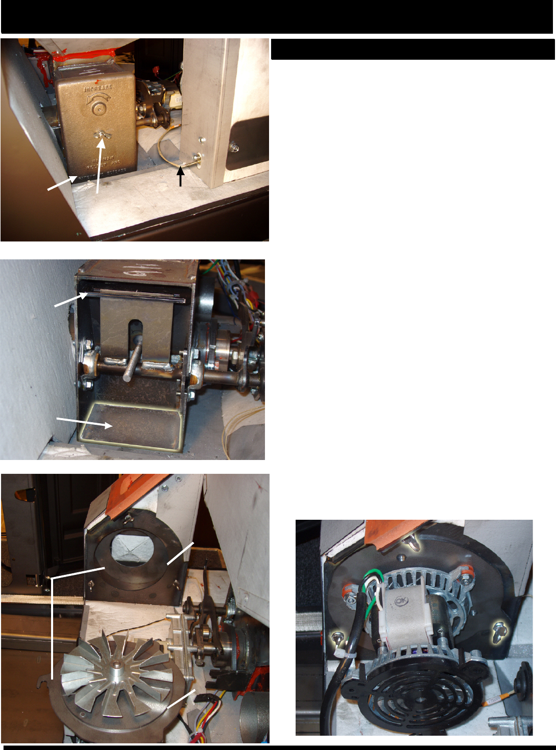
Maintenance - Cleaning
Feeder Chamber
This chamber may get a buildup of fines from the feeder
mechanism movement. This area should be checked and
cleaned at least once a year.
To remove the feeder cover:
• Remove the 5/16" wing nut.
• Slide the cover off of the threaded stud.
• Inspect and clean the inner chamber if necessary. See
Fig. 65.
• Reinstall the cover making certain it is centered on the
feeder body and tighten as tightly as you can by hand.
The combustion blower is made to be removed easily for
inspection and cleaning. See Fig. 67.
The combustion blower is mounted on a precision cut
gasketless mounting plate. This plate is held into place
with (3) thumb screws. See Fig. 67.
To remove the combustion blower:
• Turn the thumb screws counterclockwise approximately
5 turns. Rotate the entire assembly counter clockwise
until the points of the retaining slots are visible.
• Remove the blower assembly with the fan blade by
pulling it directly away from the blower housing.
• The cord on the motor is long enough to allow the motor
to be set down on the black plastic fan cover. This allows
for easy access to inspect and clean the area. See Fig.
66.
• With the blower assembly out, inspection should be done
on the surfaces of the blower assembly and the housing
opening where they meet. These surfaces MUST be clean
and free from dirt, grit, flyash, soot or nicks in the metal.
This gasketless seal relies on an extremely close
tolerance. Therefore, anything other than a clean joint may
cause exhaust gases and/or flyash to escape.
• The assembly can only be reinstalled in one position:
with the motor winding in the upward location. See Fig.
67. The mounting plate will not allow for any other position.
• Alwyas make sure that the assembly is fully seated and
the (3) thumb screws are tightened before operating the
unit.
5/16"
wing nut
ESP
Feeder
rear
chamber/
clean out
cover
Pellet
Metering
slide plate
Possible pellet
fines buildup
area.
Mating
Surface
Close
Tolerance
Close
Tolerance
Close
Tolerance
Close
Tolerance
Fig. 64
Fig.65
Fig. 66 Fig. 67
Evaluation notes were added to the output document. To get rid of these notes, please order your copy of ePrint IV now.
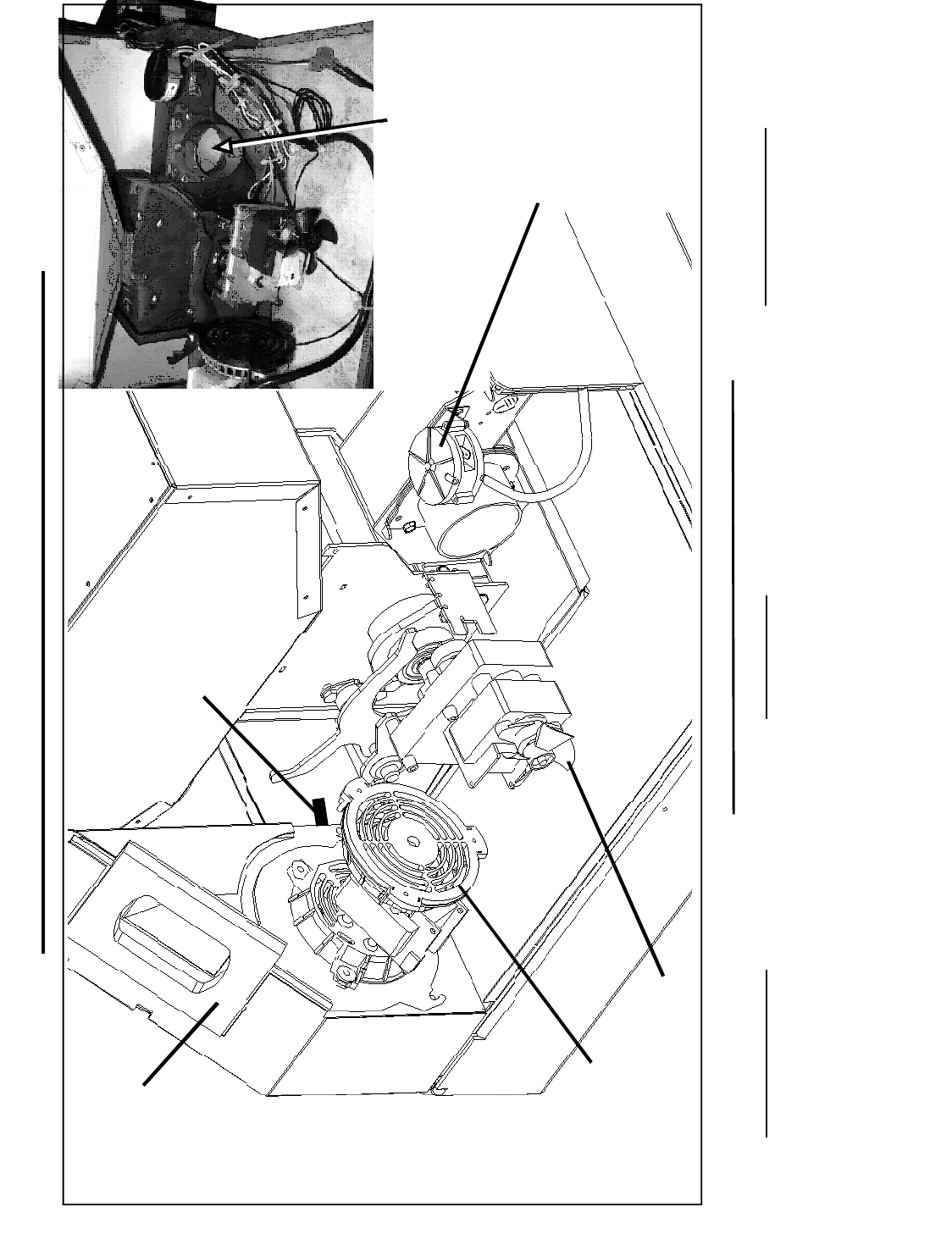
The Combustion Motor Fuse is a thermal overload
one-time fuse link within the motor windings. Should the distri-
bution motor fail with the unit operating over 80%, this fuse will
protect the other components by melting off at a set tempera-
ture. With the fuse blown, the combustion motor will stop.In
turn, the feeder motor will not operate and the stove will go out.
This may only happen when the unit is on Maximum (#7 on the
Temperature Dial, #6 on the Feed Adjuster and Distribution blower
not operating). If this fuse does blow, the unit will need service.
The Low Draft Pressure Switch is a differential pres-
sure switch that senses the pressure between the firebox
and the room. If the pressure becomes too low for proper
combustion, the switch opens, turning off the feeder motor
and the igniter element. This switch is connected into the AC
(high voltage) wires; therefore, the control may show the feeder
motor and igniter lights "on" but they are not.
31
The Control Board/ESP combination is responsible for
all high limit safety control. There are 2 high limits, one normal
operation high limit and one backup high limit. The control has
an automatic diagnostic circuit that continuously monitors the
ESP and Room Sensor for faults. If a fault should occur, the
control sends a status alert and at the same time the unit goes
down to minimum feed/minimum burn as a safety condition.
Accentra Insert Motor & Component Locations
Accentra Pellet Insert Safety Devices
Low Draft
Pressure
Switch
Feeder Motor
Combustion
Motor Distribution Blower
(under unit)
See Fig. 10, Page 8.
Silicone
sponge
docking
gasket ESP Probe
Outside Air Inlet
Backdraft Damper Assembly
Always check to see if the damper plate
swings freely inward and that the seating
edges are not covered with dirt or lint.
Evaluation notes were added to the output document. To get rid of these notes, please order your copy of ePrint IV now.

33
FEEDER DOES NOT FEED
1. No pellets in hopper.
2. Firebox draft may be too low for low draft pres-
sure switch in feeder circuit to operate. Check for
open doors, loose or missing gasket on doors or
hopper lid, faulty pressure switch.
3. Feed motor will not run until ESP
senses 165 deg. F. Maybe you did not put
enough pellets in the burn pot before lighting the
fire.
4. Something is restricting flow in the hopper or
causing the slide plate to stick.
5. Feed motor has failed.
PARTIALLY BURNED PELLETS
1. Feed rate too high.
2. Draft too low. (Check burn pot clean out slide
and door gasket).
3. Burn pot or heat exchanger tubes may need to
be cleaned.
4. Combination of all the above.
5. #6 status blink: A 6 blink control board status
indication is caused by poor or incomplete com-
bustion. The Automatic Ignition circuit board has
the ability to track the combustion through feed
settings and ESP temperatures. When the control
board has calculated poor or incomplete combus-
tion it will shut down the unit as a safety feature.
(Poor or incomplete combustion is a contributer of
creasote which may cause a chimney fire)
A 6 blink status may be caused by several things:
1. Blocked or partially blocked flue.
2. Blocked or partially blocked inlet air.
a. backdraft damper on the inlet pipe may be
stuck closed.
b. if outside air is installed the inlet cover may be
blocked.
3. The air chamber under the burnpot may be filled
with fines and small bits of ash.
4. The holes in the burnpot may be getting filled
with ash or carbon buildup.
5. Combustion blower fan blades may need
cleaned.
6. Combustion intake assembly not properly
latched.
7. No fuel in hopper
SMOKE SMELL
Seal the vent pipe joints and connection to frame
with silicone.
FIRE HAS GONE OUT
1. No pellets in hopper.
2. Draft setting is too low.
3. Something is restricting fuel flow.
4. Feed motor or draft motor has failed.
5. Power failure or blown fuse.
SMOKE IS VISIBLE COMING OUT OF VENT
1. Air-fuel ratio is too rich.
A. Feed rate too high.
B. Draft too low caused by a gasket leak.
LOW HEAT OUTPUT
1. Feed rate too low
2. Draft too low because of gasket leak.
3. Poor quality or damp pellets
4. Combination of 1. and 2.
Trouble-Shooting
Cleaning Burn Pot
Whenever your stove is not burning, take the op-
portunity to scrape the burn pot to remove carbon
buildup. A vacuum cleaner is handy to remove the resi-
due. Be sure the stove is cold if you use a vacuum.
Carbon buildup can be scraped loose with the fire
burning using the special tool provided with your stove.
Scrape the floor and sides of the burn pot. The carbon
will be pushed out by the incoming fuel. Always wear
gloves to do this.
Removing Ashes
Turn the Temp Dial to number 1 approximately 30
minutes before removing ashes. This will result in a
cooler stove and ash pan.
Maximum Feed Adjuster settings are not needed
in most cases. Operating in the normal range (#4) is
recommended when maximum heat output is not re-
quired. The ESP probe prevents the stove from being
over-fired.
Keep the stove free of dust and dirt.
Helpful Hints
Fuel
Pellet fuels are put into 3 categories in terms of
ash content. Premium at 1% or less, Standard at 3% or
less and all others at 3% or more.
The Accentra is capable of burning all 3 categories
of pellets due to a patented feeder and burn pot system.
It should be noted, however, that higher ash con-
tent will require more frequent ash removal and may
provide less BTU's per pound. Normally, standard and
high ash pellets cost less than premium pellets and can
be cost effective when burned in the Accentra.
The moisture content must not exceed 8%. Higher
moisture will rob BTU's and may not burn properly.
Evaluation notes were added to the output document. To get rid of these notes, please order your copy of ePrint IV now.
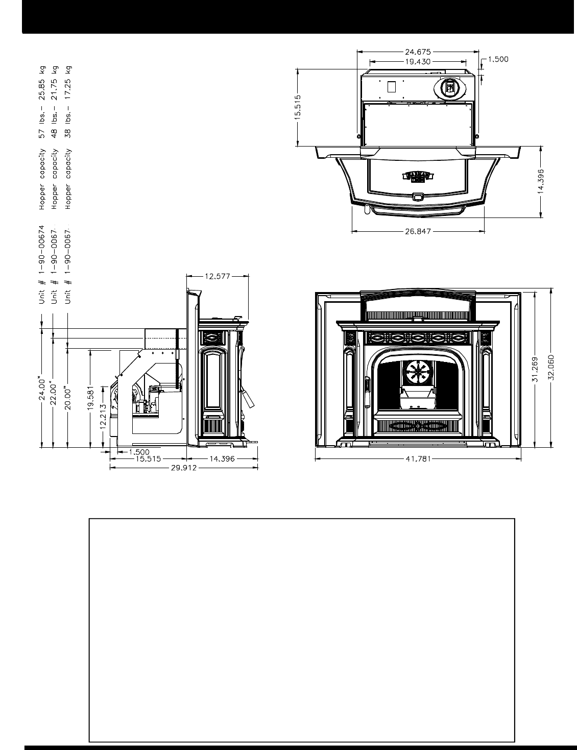
34
Specifications
Weight 450 lbs.
Blower 180 cfm
Hopper Capacity 57 lbs. (24" hopper #1-90-00674)
Fuel Wood Pellets
Outside Air Size 3 inches
Fuse Rating 6 amp
BTU Range 0 to 42,000
Feed Rate .75 lbs./hr. on minimum(on maintenance)
5 lbs./ hr. on maximum
Vent Size 4 inch Pellet Vent Pipe, standard,
3 inch Pellet Vent Pipe, option
Maximum Wattage 440 Watts (Start cycle and test)
Start Cycle Wattage 340 Watts
Normal Run Wattage255 Watts
5
6
Evaluation notes were added to the output document. To get rid of these notes, please order your copy of ePrint IV now.
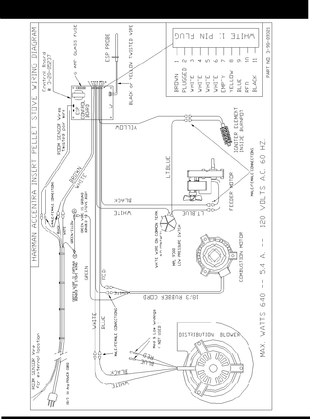
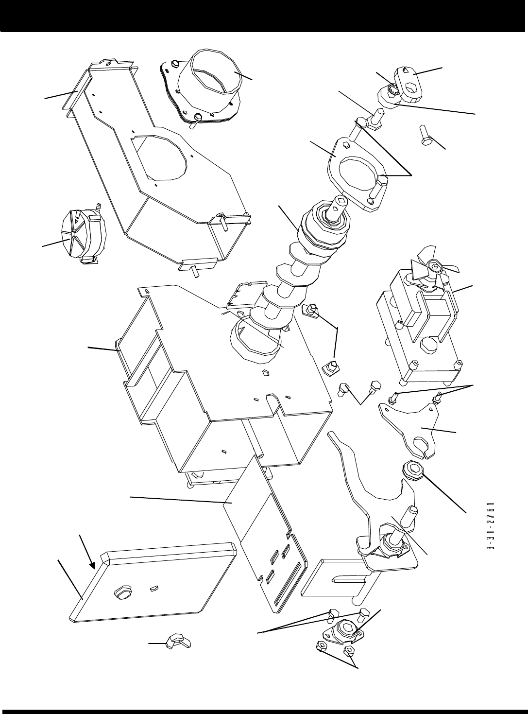
36
Accentra Insert Feeder Parts
10-24 x 1/2 screws
3-30-1102405016
Cover
2-00-247217
Rubber Grommet Motor Mount
2-00-01534 Gearmotor
3-20-60906
(2) Flange bolts
3-30-2252006213
(2) 5/16-18 T Nut
3-31-23756186
(2) 5/16-18 x 1 1/4
3-30-1311812513
1/4-20x1 Bolt
3-30-1252007514
HCS 3/8-16x
3-30-1371608713
Bearing Retainer
2-00-04035
Auger
3-50-00365
Intake Air Box Assembly
1-10-674045
Differential Pressure Switch
3-20-9301
Feeder Body Weldment
1-10-00910
Slide Plate
1-10-08037
Cam Block Bearing
3-31-3014
Pusher Arm Weldment
1-10-08535
(2) 1/4-20 nuts
3-30-80252013
2 1/4-20 flange bolts
3-30-2252006213
Bearing
3-31-3614087
Air Intake Weldment
1-10-06466
Lock Washer
3-30-91113031
Cam Block
3-00-00153
Cover Gasket
3-44-247218
Evaluation notes were added to the output document. To get rid of these notes, please order your copy of ePrint IV now.

37
See page 35 for
Feeder Part Numbers
Accentra Insert Parts List
Description Part Number
Hopper Lid Gasket 3-44-375501
(5.25',1/2 x 3/8" silicone w/PSA)
Ignitor Element Assembly 1-10-06620
Wiring Harness 3-20-08727
Burn Pot Weldment 1-10-00675
Heat Exchanger Cover (2) 3-00-674050
Center Medallion (1) 3-00-674060
Arrow Scraper 2-00-773850
Flame Guide 3-00-674069
Gear Motor 3-20-60906
Thermister Probe 3-20-00744
Room Sensor 3-20-00906
Circuit Board G5237 3-20-05237
2 5/8" Black CCW Fan Blade(auger motor) 3-20-2046399
Differential Switch 3-20-9301
4 3/4" Single Paddle Combustion Fan Blade 3-21-00661
Combustion Blower 3-21-08639
Distribution Blower 3-21-47120
Tailpipe Insulator 3-44-674102
White/Black Control Knob (3) 3-31-00968
Control Knob Shaft (3) 3-31-00982
Front Glass w/gasket 3-40-674090
Docking Gasket (red silicone) 3-44-06108
Wood Handle 3-40-00123
Wiring Diagram 3-90-09321
Control Panel Sticker 3-90-06655
Owner's Manual 3-90-00674
Hopper Lid Label 3-90-08416
Ash Pan Assembly 1-10-674030
Cast Hopper Lid 3-00-674059
Ball Spring Plunger (3) 3-31-5500
Glass Clips (4) 2-00-249140
Power Cord 3-20-674200
Flue Brush 3-40-00126
3/8" Black Door Gasket (5 1/2 ft.) 3-44-37525
Outside Air Assembly 1-10-674080
Log Kit 1-00-674099
Zero Clearance Cabinet 1-10-674070
Zero Clearance Box Flue Pipe Support 1-00-674119
4" PL vent stub 1-00-674040
3" PL vent stub 1-00-674039
Options:
Evaluation notes were added to the output document. To get rid of these notes, please order your copy of ePrint IV now.

38
Harman Gold Warranty
Harman Stove Company warrants its products to be free from defects in material or workmanship, in normal use and
service, for a period of 6 years from the date of sales invoice and for mechanical and electrical failures, in normal use and
service, for a period of 3 years from the date of sales invoice.
If defective in material or workmanship, during the warranty period, Harman Stove Company will, at its option, repair or
replace the product as described below.
The warranty above constitutes the entire warranty with respect to Harman Stove Company products. HARMAN STOVE
COMPANY MAKES NO OTHER WARRANTY, EXPRESSED OR IMPLIED, INCLUDING “ANY” WARRANTY OF
MERCHANTABILITY, OR WARRANTY OF FITNESS FOR A PARTICULAR PURPOSE. No employee, agent, dealer, or
other person is authorized to give any warranty on behalf of Harman Stove Company. This warranty does not apply if the
product has been altered in any way after leaving the factory. Harman Stove Company and its agents assume no liability for
“resultant damages of any kind” arising from the use of its products. In addition, the manufacturer and its warranty administra-
tor shall be held free and harmless from liability from damage to property related to the operation, proper or improper, of the
equipment.
THERE ARE NO WARRANTIES WHICH EXTEND BEYOND THE DESCRIPTION ON THE FACE HEREOF.
THESE WARRANTIES APPLY only if the device is installed and operated as recommended in the user’s manual.
THESE WARRANTIES WILL NOT APPLY if abuse, accident, improper installation, negligence, or use beyond rated
capacity causes damage.
HOW TO MAKE A CLAIM - Any claim under this warranty should be made to the dealer from whom this appliance was
purchased. Then contact is made with manufacturer, giving the model and serial numbers, the date of purchase, your dealer’s
name and address, plus a simple explanation of the nature of the defect. Extra costs such as mileage and overtime are not
covered. Nuisance calls are not covered by these warranties.
THIS WARRANTY IS LIMITED TO DEFECTIVE PARTS - REPAIR AND/OR REPLACEMENT AT
HARMAN STOVE COMPANY’S OPTION AND EXCLUDES ANY INCIDENTAL AND CONSEQUENTIAL
DAMAGES CONNECTED THEREWITH.
WARRANTY EXCLUSIONS: Failure due, but not limited to, fire, lightning, acts of God, power failures and/or surges,
rust, corrosion and venting problems are not covered. Damage and/or repairs including but not limited to; remote controls,
filters, fuses, knobs, glass, ceramic brick panels, ceramic fiber afterburners, door packing, tile, ceramic log sets, paint, batteries
or battery back-up and related duct work are not covered. Also excluded from this warranty are consumable or normal wear
items including but not limited to; flame guides, grates, coal bars, afterburner hoods, fire brick, gaskets. Additional exclusions
for corn stoves are burnpot housing weldment, burnpot grate weldment (pellet or corn), burnpot front plate (pellet or corn),
burnpot front plate lock, corn auger extension, ceramic insert, and ceramic insert plate. Additional or unusual utility bills incurred
due to any malfunction or defect in equipment and the labor cost of gaining access to or removal of a unit that requires special
tools or equipment are not covered. Maintenance needed to keep the stove in “good operating condition” is not covered. This
includes, but is not limited to, cleaning, adjustment of customer controls and customer education. Labor, materials, expenses
and/or equipment needed to comply with law and/or regulations set forth by any governmental agencies are not covered.
This Warranty provides specific legal rights and the consumer may have other rights that vary from state to state.
In the event of change in ownership, the remaining portion of this warranty may be transferred to the new owner by
sending the new owner information to the Harman Stove Company.
PLEASE READ THE LITERATURE BY THE MANUFACTURER FOR THE VARIOUS ACCESSORY DEVICES.
THE MANUFACTURER WARRANTS THESE ACCESSORY DEVICES, NOT HARMAN STOVE COMPANY OR THEIR
WARRANTY ADMINISTRATOR. FURTHERMORE, THESE ACCESSORY DEVICES MUST BE INSTALLED AND
USED ACCORDING TO THE RECOMMENDATIONS OF THE MANUFACTURER.
REMEDIES - The remedies set forth herein are exclusive and the liability of seller with respect to any contract or sale or
anything done in connection therewith, whether in Contract, in tort, under any warranty, or otherwise, shall not, except as herein
expressly provided, exceed the price of the equipment or part of which such liability is based.
CLARIFY - The above represents the complete warranty, which is given in connection with stoves, manufactured by
Harman Stove Company. No other commitments, verbal or otherwise, shall apply except by a written addendum to this
warranty.
HARMAN GOLD WARRANTY
6 YEAR TRANSFERABLE LIMITED
WARRANTY (Residential)
1 YEAR LIMITED WARRANTY (Commercial)
Evaluation notes were added to the output document. To get rid of these notes, please order your copy of ePrint IV now.
