Harman Accentra Insert Owner S Manual
2014-07-05
: Harman Harman-Accentra-Insert-Owner-S-Manual harman-accentra-insert-owner-s-manual harman pdf
Open the PDF directly: View PDF ![]() .
.
Page Count: 48
3-90-00674R28_12/13
SAVE THESE INSTRUCTIONS.
Installation & Operating Manual
Model(s):
Accentra Pellet Insert
NOTICE: SAVE THESE INSTRUCTIONS
Hot glass will cause burns.
• Donottouchglassuntilitiscooled
• NEVERallowchildrentotouchglass
• Keepchildrenaway
• CAREFULLYSUPERVISEchildreninsameroomas
stove.
• Alertchildrenandadultstohazardsofhightemperatures.
High temperatures may ignite clothing or other
ammable materials.
• Keepclothing,furniture,draperiesandotherammable
materialsaway.
HOT SURFACES!
Glassandothersurfacesarehotduring
operationandcooldown.
WARNING
!
To obtain a French translation of this manual, please
contactyourdealerorvisitwww.harmanstoves.com
Pourobtenirunetraductionfrançaisedecemanuel,s’il
vous plaît contacter votre revendeur ou visitez www.
harmanstoves.com
NOTE
SAFETY NOTICE
PLEASE READ THIS ENTIRE MANUAL BEFORE YOU INSTALL AND USE YOUR NEW ROOM HEATER. FAILURE TO
FOLLOW INSTRUCTIONS MAY RESULT IN PROPERTY DAMAGE, BODILY INJURY, OR EVEN DEATH.
FOR USE IN THE U.S. AND CANADA. SUITABLE FOR INSTALLATION IN MOBILE HOMES
IF THIS APPLIANCE IS NOT PROPERLY
INSTALLED, A HOUSE FIRE MAY RESULT. FOR YOUR SAFETY, FOLLOW
INSTALLATION DIRECTIONS. DO NOT USE MAKESHIFT COMPROMISES.
CONTACT LOCAL BUILDING OR FIRE OFFICIALS ABOUT RESTRICTIONS AND INSTALLATION INSPECTION
REQUIREMENTS IN YOUR AREA.
CONTACT YOUR LOCAL AUTHORITY (SUCH AS MUNICIPAL BUILDING DEPARTMENT, FIRE DEPARTMENT, FIRE
PREVENTION BUREAU, ETC.) TO DETERMINE THE NEED FOR A PERMIT.
CETTE GUIDE D'UTILISATION EST DISPONIBLE EN FRANCAIS. CHEZ VOTRE CONCESSIONNAIRE DE HARMAN.
This Fireplace insert may be installed into a masonry replace, an approved manufactured wood burning replace
(see page 25), Or, It may be built in to a wall or mantle system when using the optional zero clearance cabinet (see
page 26).
Contact your local dealer with questions on installation,
operationorservice.
Tested and
Listed By
Portland
Oregon USA
Test réalisés par OMNI-Test Laboratories, Inc.
Report #/Rapport #135-S-12-2, 135-S-12b-6
Tested to/Testé à: ASTM E1509-04, ULC/ORD-C1482-M1990,
ULC-S628-93
This pellet burning appliance has been tested and listed for use in
Manufactured Homes in accordance with
OAR 814-23-900 through 814-23-909
Normes Européennes:
NF EN 14785 CETIAT – Déc. 2006
AEMC MESURES EN 50366 – Déc. 2006
EMITECH, APAVE & BFP Electronique – Février 2004
EN 55014-1, EN 55014-2, EN 61000-3-2, EN 61000-3-3
PREVENTION DES INCENDIES
Respecter scrupuleusement les instructions du constructeur pour
l’installation et les consignes de fonctionnement. Respecter les
règles de sécurité en vigueur dans votre région.
AVERTISSEMENT POUR MOBILE HOMES : Ne pas installer dans
une chambre. Il est impératif de prévoir une prise d’air extérieur.
L’intégrité structurale du plancher, du plafond et des murs doit être
strictement préservée.
Se reporter aux instructions du fabricant et aux réglementations
spéci ques locales concernant les précautions requises lors de la
traversée d’un mur ou d’un plafond.
Contrôler et nettoyer fréquemment tout le système d’évacuation des
fumées conformément aux recommandations du constructeur.
Réaliser l’évacuation des fumées en utilisant des conduits « Spécial
granulés » de Ø 125 mm ou de la gaine exible inox double peau
Ø 125 mm à l’aide d’un adaptateur adéquat comme indiqué dans la
notice d’utilisation.
Ne pas raccorder ce poêle à un conduit de cheminée déjà utilisé
pour un autre appareil.
FONCTIONNE EXCLUSIVEMENT AVEC DES GRANULES DE BOIS.
Consommation maximum : 2,27 kg/h
Caractéristiques électriques :
240 VAC – 50 Hz – Intensité au démarrage 2,0 A
Intensité fonctionnement normal 1,1 A
Tenir le cordon d’alimentation à l’écart du poêle.
DANGER : Risque d’électrocution. Débrancher l’appareil avant toute
intervention.
Pour une information plus complète, se reporter à la notice
d’utilisation.
Ne remplacer la vitre qu’avec une vitre céramique 5 mm de même
qualité disponible auprès de votre revendeur.
Tenir la porte frontale et le couvercle de trémie hermétiquement clos
durant le fonctionnement de l’appareil.
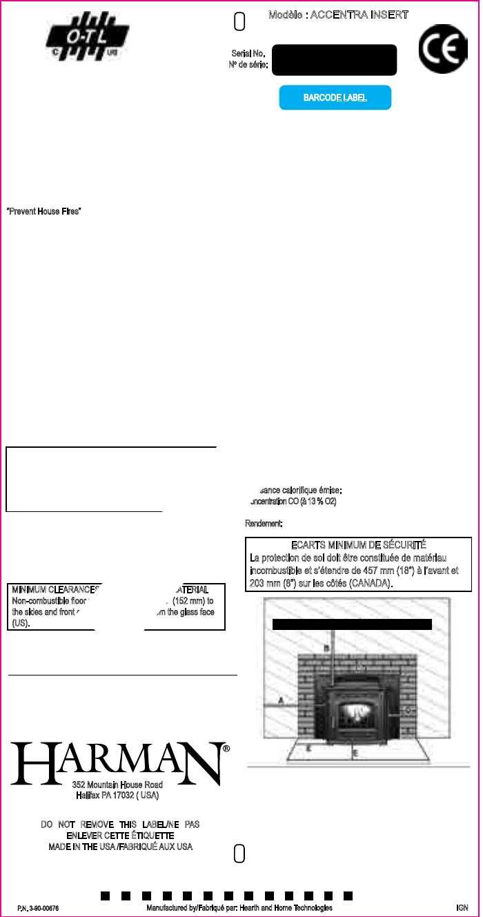
Puissance calori que émise: Nominale: 10,5 KW Réduite: 1,8 KW
Concentration CO (à 13 % O2)
à puissance nominale: < 0,02 % à puissance réduite: < 0,04 %
Rendement: à puissance nominale: 84 % à puissance réduite: 73%
DO NOT REMOVE THIS LABEL/NE PAS
ENLEVER CETTE ÉTIQUETTE
MADE IN THE USA /FABRIQUÉ AUX USA
Modèle:ACCENTRAINSERT
Appareildechauffageàgranulésdebois
“Prevent House Fires”
Install and use only in accordance with the manufacturer’s installa-
tion and operation instructions. Contact local building or re of cials
about restrictions and inspection in your area.
WARNING: FOR MANUFACTURED HOMES: Do not install appli-
ance in a sleeping room. An outside combustion air inlet must be
provided. The structural integrity of the manufactured home oor,
ceiling and walls must be maintained.
Refer to manufacturer’s instructions and local codes for precautions
required for passing chimney through a combustible wall or ceiling.
Inspect and clean exhaust venting system frequently in accordance
with manufacturer’s instructions.
Use a 3” or 4” diameter type “L” or “PL” venting system, or 4” stain-
less steel ex as per owner’s manual.
Do not connect this unit to a chimney ue servicing another ap-
pliance.
FOR USE WITH PELLETIZED WOOD FUEL OR UP TO A 50%
CORN AND PELLET MIXTURE ONLY.
Input Rating Max: 5 lb. fuel/hr.
Electrical Rating: 240 VAC, 50 Hz, Start 2.0 AMPS, Run 1.1 AMPS
US Electrical Rating: 115 VAC, 60 Hz, Start 4.1 AMPS, Run 2.1 AMPS
US Environmental Protection Agency
This model is exempt from EPA Certi cation under 40 CFR 60.531
by de nition (wood heater(A) “Air-to-Fuel Ratio”)
Agence Américaine pour la Protection de l’Environnement
Ce modèle est dispensé par EPA certi cation d’après
40 CFR 60.531 par dé nition
[ Appareil à bois (A) « Ratio air/combustible »]
12” (305mm) Mantel/Manteau de Cheminée
Sidewall/Mur de Côté
Trim/Panneau de Moulure
Emission of CO in Combustion:
Nominal Heat Output: <.02%, Reduced Heat Output: <.04%
Flue Gas Temperature: 224 C
Thermal Output: 10.5kW
Energy Ef ciency: Nominal: 84%, Reduced: 73%
Route power cord away from unit.
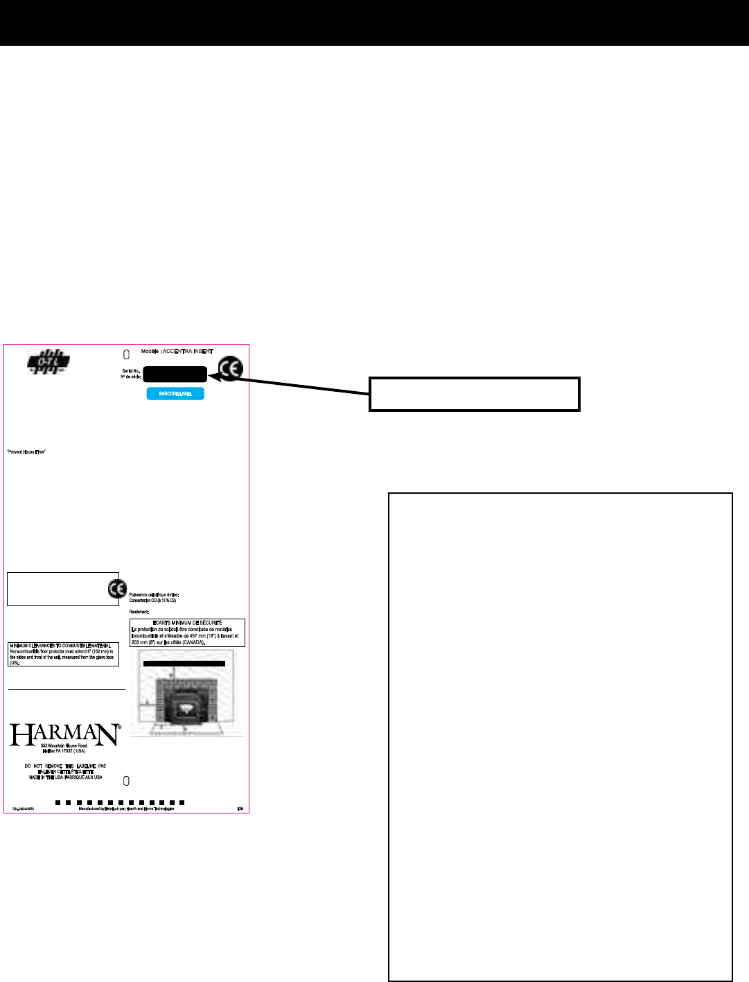
MINIMUM CLEARANCES TO COMBUSTIBLE MATERIAL
Non-combustible oor protector must extend 6” (152 mm) to
the sides and front of the unit, measured from the glass face
(US).
ECARTS MINIMUM DE SÉCURITÉ
La protection de sol doit être constituée de matériau
incombustible et s’étendre de 457 mm (18”) à l’avant et
203 mm (8”) sur les côtés (CANADA).
352 Mountain House Road
Halifax PA 17032 ( USA)
P.N. 3-90-00676 IGN
A. Insert Body to side wall - 10” (254 mm)
B. Insert Body to 12” (305mm) Mantel/ Manteau de
Cheminée - 12” (305 mm)
C. Insert Body to combustible trim above - 3/4” (19 mm)
D. Insert Body to side trim - 6” (152 mm)
E. Floor protection. Measured from glass. - 6” (U.S.) -OR
8” (203mm) to sides and 18” (457mm) in front (CANADA)
DANGER: Risk of electrical shock. Disconnect power supply before
servicing.
For further instruction refer to owner’s manual.
Replace glass only with 5mm ceramic available from your dealer.
Keep viewing and ash removal doors tightly closed during operation.
BARCODE LABEL
008
Serial No.
No de série:
Rev D
Date of Manufacture / Date de fabrication
2013 2014 2015 JAN FEB MAR APR MAY JUN JUL AUG SEP OCT NOV DEC
Manufactured by/Fabriqué par: Hearth and Home Technologies
11”
5.75”
SAMPLE
3
3-90-00674R28_12/13
Introduction
Hearth & Home Technologies
352MountainHouseRoad
Halifax,PA17032
www.harmanstoves.com
Table of Contents
Automatic Operation 4
Manual Operation 6
ESP Control 8
Assembly & Installation 9
Venting 21
Maintenance 28
Trouble-Shooting 33
Specications 34
Wiring Diagram 35
Warranty 36
Service Parts List 38
Power Failures / Back-up 44
Fuel Specications 45
Corn / Pellet Mixture 46
TheAccentraPelletInsertwillgiveyoumoreheat,bettertemperaturecontrolandalevelofconvenienceyouwon’tndin
anyotherpelletburninginsert.TheAccentraInsert’smanyoutstandingfeaturesmakeitthebestvaluepelletinsertonthe
markettoday.
TheAccentra’sversatiledesignletsyouconvertaheatwastingreplaceintoanefcientheatingsource.TheAccentraInsert
couldalsobeareplacehearthforyourhomethatdoesn’trequireachimney.Aspecialzeroclearancereplacekitconverts
theAccentrainsertintoareplacethatcanbeplacedinvirtuallyanycorneroragainstanywallofyourhome.
TheAccentra’son-boardmicroprocessorconstantlysensesroomtemperatureandautomaticallymakesadjustmentsinthe
feedrateandairsupplysoyougetjusttherightamountofheat24hoursaday.Thisremarkabletechnologyletsyoullthe
hopper,setthedesiredtemperatureandwalkaway.TheAccentrainsertlightsautomatically,bringstheroomuptotheexact
temperatureandwillturnoffifnoheatisrequired.Nootherpelletinsertofferssuchaccurateandtroublefreetemperature
control.Thecontroltechnologygivesyouthewidestheatoutputrangeofanyinsertonthemarketmakingitanidealchoice
totakethechilloffinthespringandfallandtoheatyourhomeduringthecoldestmonthsofthewinter.
AswithallHarmanpelletstoves,maintenanceisminimalandcleaningiseasy.TheAccentraInsertletsyouburnclosetoa
tonofpelletsbeforeashremovalisneeded.Andwhatisevenbetter,theHarmanInsertTrackSystemletsyouslidetheinsert
outofthereplacesothatitcanbecleanedorservicedwithouthavingtodisconnecttheventingsystem.Thisinnovative
designisonlyavailableonHarmanpelletinsertsandletsyoueasilyreachkeycomponentsforcleaning.
Note:Thisapplianceisalsoapprovedforinstallationintoa
shop.
Appliance Certication.
Model:AccentraInsert
Test Lab:Omni-TestLaboratories
Type:PelletBurningFireplaceInsert/RoomHeater
Standard(s):ASTME1509-04,ULCS628-93andULC
C1482-M1990.InaccordancewithOAR814-23-900
through814-23-909
Report #:135-S-12-2
Tested and
Listed By
Portland
Oregon USA
Test réalisés par OMNI-Test Laboratories, Inc.
Report #/Rapport #135-S-12-2, 135-S-12b-6
Tested to/Testé à: ASTM E1509-04, ULC/ORD-C1482-M1990,
ULC-S628-93
This pellet burning appliance has been tested and listed for use in
Manufactured Homes in accordance with
OAR 814-23-900 through 814-23-909
Normes Européennes:
NF EN 14785 CETIAT – Déc. 2006
AEMC MESURES EN 50366 – Déc. 2006
EMITECH, APAVE & BFP Electronique – Février 2004
EN 55014-1, EN 55014-2, EN 61000-3-2, EN 61000-3-3
PREVENTION DES INCENDIES
Respecter scrupuleusement les instructions du constructeur pour
l’installation et les consignes de fonctionnement. Respecter les
règles de sécurité en vigueur dans votre région.
AVERTISSEMENT POUR MOBILE HOMES : Ne pas installer dans
une chambre. Il est impératif de prévoir une prise d’air extérieur.
L’intégrité structurale du plancher, du plafond et des murs doit être
strictement préservée.
Se reporter aux instructions du fabricant et aux réglementations
spéci ques locales concernant les précautions requises lors de la
traversée d’un mur ou d’un plafond.
Contrôler et nettoyer fréquemment tout le système d’évacuation des
fumées conformément aux recommandations du constructeur.
Réaliser l’évacuation des fumées en utilisant des conduits « Spécial
granulés » de Ø 125 mm ou de la gaine exible inox double peau
Ø 125 mm à l’aide d’un adaptateur adéquat comme indiqué dans la
notice d’utilisation.
Ne pas raccorder ce poêle à un conduit de cheminée déjà utilisé
pour un autre appareil.
FONCTIONNE EXCLUSIVEMENT AVEC DES GRANULES DE BOIS.
Consommation maximum : 2,27 kg/h
Caractéristiques électriques :
240 VAC – 50 Hz – Intensité au démarrage 2,0 A
Intensité fonctionnement normal 1,1 A
Tenir le cordon d’alimentation à l’écart du poêle.
DANGER : Risque d’électrocution. Débrancher l’appareil avant toute
intervention.
Pour une information plus complète, se reporter à la notice
d’utilisation.
Ne remplacer la vitre qu’avec une vitre céramique 5 mm de même
qualité disponible auprès de votre revendeur.
Tenir la porte frontale et le couvercle de trémie hermétiquement clos
durant le fonctionnement de l’appareil.
Puissance calori que émise: Nominale: 10,5 KW Réduite: 1,8 KW
Concentration CO (à 13 % O2)
à puissance nominale: < 0,02 % à puissance réduite: < 0,04 %
Rendement: à puissance nominale: 84 % à puissance réduite: 73%
DO NOT REMOVE THIS LABEL/NE PAS
ENLEVER CETTE ÉTIQUETTE
MADE IN THE USA /FABRIQUÉ AUX USA
Modèle:ACCENTRAINSERT
Appareildechauffageàgranulésdebois
“Prevent House Fires”
Install and use only in accordance with the manufacturer’s installa-
tion and operation instructions. Contact local building or re of cials
about restrictions and inspection in your area.
WARNING: FOR MANUFACTURED HOMES: Do not install appli-
ance in a sleeping room. An outside combustion air inlet must be
provided. The structural integrity of the manufactured home oor,
ceiling and walls must be maintained.
Refer to manufacturer’s instructions and local codes for precautions
required for passing chimney through a combustible wall or ceiling.
Inspect and clean exhaust venting system frequently in accordance
with manufacturer’s instructions.
Use a 3” or 4” diameter type “L” or “PL” venting system, or 4” stain-
less steel ex as per owner’s manual.
Do not connect this unit to a chimney ue servicing another ap-
pliance.
FOR USE WITH PELLETIZED WOOD FUEL OR UP TO A 50%
CORN AND PELLET MIXTURE ONLY.
Input Rating Max: 5 lb. fuel/hr.
Electrical Rating: 240 VAC, 50 Hz, Start 2.0 AMPS, Run 1.1 AMPS
US Electrical Rating: 115 VAC, 60 Hz, Start 4.1 AMPS, Run 2.1 AMPS
US Environmental Protection Agency
This model is exempt from EPA Certi cation under 40 CFR 60.531
by de nition (wood heater(A) “Air-to-Fuel Ratio”)
Agence Américaine pour la Protection de l’Environnement
Ce modèle est dispensé par EPA certi cation d’après
40 CFR 60.531 par dé nition
[ Appareil à bois (A) « Ratio air/combustible »]
12” (305mm) Mantel/Manteau de Cheminée
Sidewall/Mur de Côté
Trim/Panneau de Moulure
Emission of CO in Combustion:
Nominal Heat Output: <.02%, Reduced Heat Output: <.04%
Flue Gas Temperature: 224 C
Thermal Output: 10.5kW
Energy Ef ciency: Nominal: 84%, Reduced: 73%
Route power cord away from unit.
MINIMUM CLEARANCES TO COMBUSTIBLE MATERIAL
Non-combustible oor protector must extend 6” (152 mm) to
the sides and front of the unit, measured from the glass face
(US).
ECARTS MINIMUM DE SÉCURITÉ
La protection de sol doit être constituée de matériau
incombustible et s’étendre de 457 mm (18”) à l’avant et
203 mm (8”) sur les côtés (CANADA).
352 Mountain House Road
Halifax PA 17032 ( USA)
P.N. 3-90-00676 IGN
A. Insert Body to side wall - 10” (254 mm)
B. Insert Body to 12” (305mm) Mantel/ Manteau de
Cheminée - 12” (305 mm)
C. Insert Body to combustible trim above - 3/4” (19 mm)
D. Insert Body to side trim - 6” (152 mm)
E. Floor protection. Measured from glass. - 6” (U.S.) -OR
8” (203mm) to sides and 18” (457mm) in front (CANADA)
DANGER: Risk of electrical shock. Disconnect power supply before
servicing.
For further instruction refer to owner’s manual.
Replace glass only with 5mm ceramic available from your dealer.
Keep viewing and ash removal doors tightly closed during operation.
BARCODE LABEL
008
Serial No.
No de série:
Rev D
Date of Manufacture / Date de fabrication
2013 2014 2015 JAN FEB MAR APR MAY JUN JUL AUG SEP OCT NOV DEC
Manufactured by/Fabriqué par: Hearth and Home Technologies
11”
5.75”
Pleasecopy
yourserial
numberfrom
thelabelonyourstovetotheboxbelow.
SERIAL NUMBER
4
3-90-00674R28_12/13
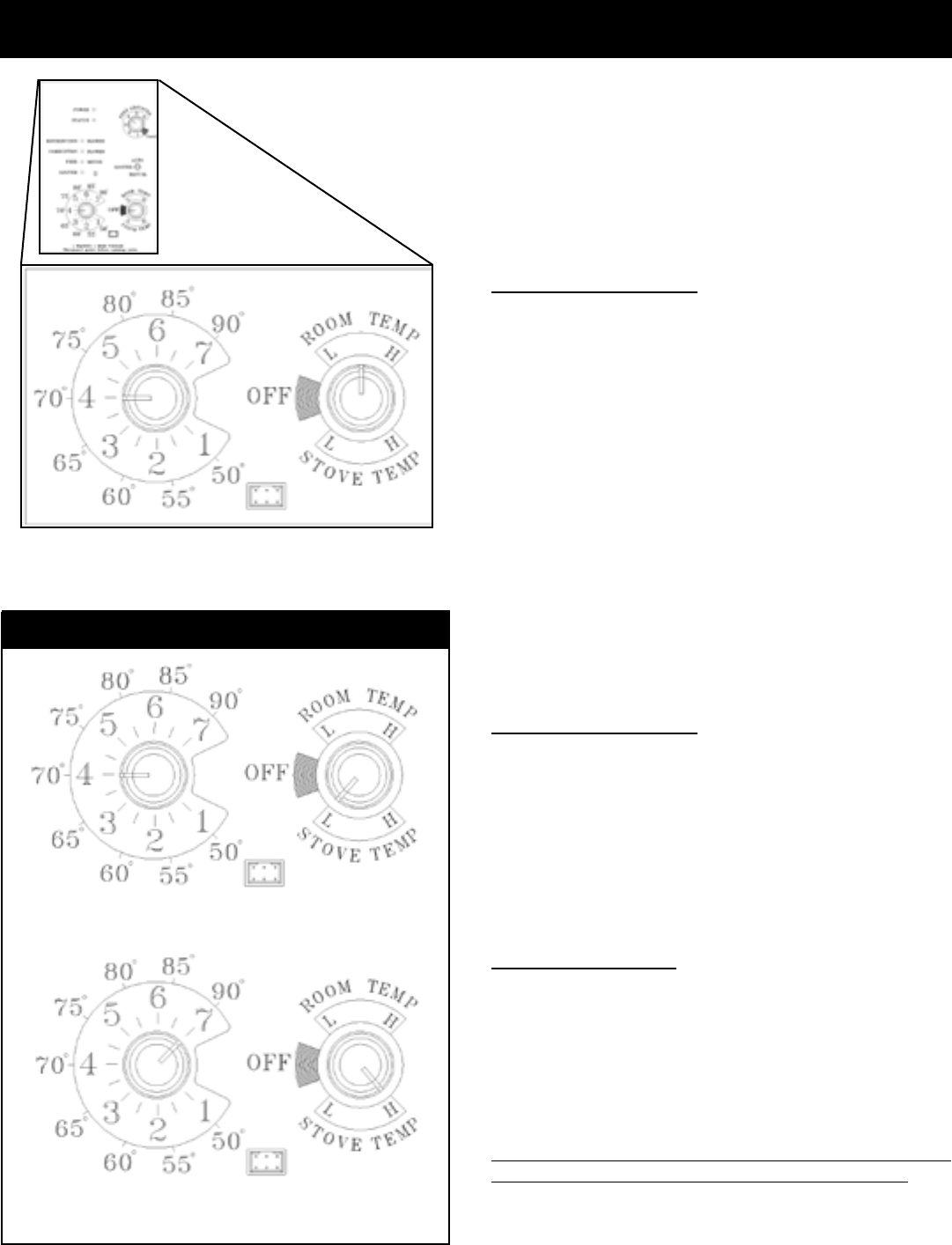
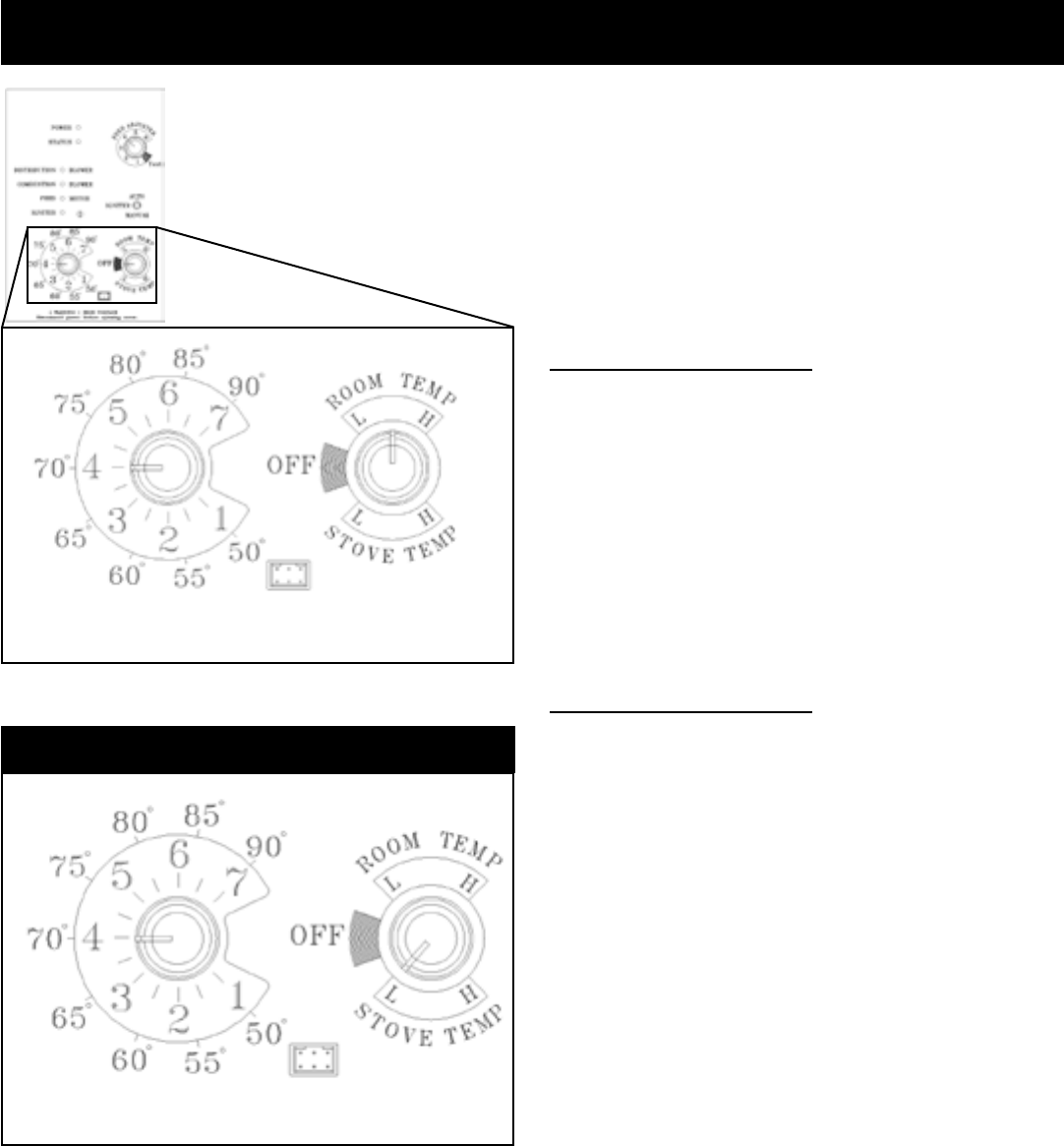
Igniter Switch to "AUTO" (up position)
Makesuretheunitispluggedintoaproperlygrounded,120
VAC,60Hzelectricalsource.Thepowerlightshouldbethe
onlylightlit.
Note: Be sure there is no fuel or other combustibles in
the ash pan prior to lighting.
1. TurnModeSelectorto"OFF".
2. Fillhopperwithpellets.
3. Cleanburnpotwithscraper,ifnecessary.
4. Ifstartingafteranemptyhopper,turnFeedAdjusterto
"TEST"(forone60secondcycle).2Thiswillowpellets
intotheaugertubeandalsoallowyoutocheckthemotors
foroperation.NOTE: The auger motor will not operate
with the view door or hopper lid open.
5. TurnFeedAdjusterto#4.4
6. FliptheIgniterSwitchupintothe"AUTO"position.
7.TurntheTemperatureDialtothedesiredroomtemperature.
8. Turn Mode Selector to Room Temperature or Stove
Temperature.
9. Fillhopperwithpelletsandremoveashesasrequired.
Keep the hopper lid and firebox doors closed while in
operation.Maintaindoorsealsingoodcondition.Failureto
dosowillaffectoperationoftheapplianceandmaypermit
escapeofsmokeorgasesintothelivingspace.
Automatic Start Up
1. Fines are small pieces of broken pellets (sawdust). Fines do
not ow easily and often build up on the hopper funnel bottom
angles. These nes can be pushed into the feeder opening and
then ll the hopper with pellets. As the system works, they will
be burned.
2. The "TEST" cycle will operate the feed motor for exactly one
minute. Turning to "TEST" again and again may load too much
fuel into the burn pot causing excessive smoke on start-up.
3. The rebox low pressure switch will not allow the auger motor
or the igniter element to operate if the view door is open.
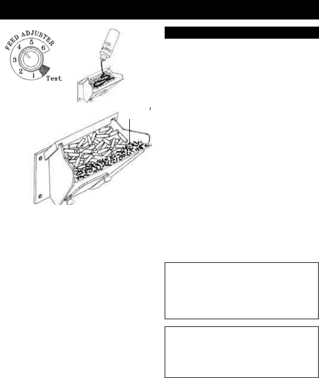
4. Adjust Feed Rate. If this is your rst re or you are trying different
pellets, set the feed adjuster to #4, Fig. 1. This is a conservative
number and will probably need to be increased. After you know
a feed rate setting that works well, use that setting. Remember,
if your feed rate is too high you may waste fuel.
5. This is usually a weekly maintenance procedure. Cleaning the
burn pot with the scraper with a small amount of new fuel in the
bottom is not a problem. First, scrape the ashes off the front of
the burn pot into the ash pan. Then scrape the holed surface
downward into the burn pot. When the stove feeds, these
scrapings will be pushed out by the feeder.
6. The ash pan can hold the ashes from approximately 1 ton of
premium fuel. This means the ashes will only need to be emptied
a few times a year.
7. Setting the feed adjuster # for maximum burn: With the unit
burning in "AUTO", turn to "Stove Mode" and put the fan on
"H". Set the Temperature Dial to #7. Allow the unit to burn for
about 30 minutes and check ash on front of burn pot. Fig. 2.
If the ash line is larger than 1", turn the feed adjuster from #4
to #5. Allow another 30 minutes of burn time and check again.
If, at #6 setting, a 1" or less ash bed is not obtainable, it is not
a problem. The 1" ash bed is only at maximum burn rate and
during normal operation, the ash bed will be larger.
See Note 7.
Fig.2
1"
NEVER USE GASOLINE, GASOLINE-TYPE LANTERN
FUEL, KEROSENE, CHARCOAL LIGHTER FLUID, OR
SIMILAR LIQUIDS TO START OR 'FRESHEN UP' A FIRE
IN THIS HEATER. KEEP ALL SUCH LIQUIDS WELL
AWAY FROM THE HEATER, WHILE IN USE.
WARNING
Fig.1
WARNING
BURNING GARBAGE, USE OF IMPROPER FUELS,
FIRE STARTERS OR ALTERING THE STOVE FOR
HIGHER HEAT OUTPUT MAY CAUSE DAMAGE TO THE
STOVE AND COULD RESULT IN A HOUSE FIRE. USE
ONLY APPROVED FUELS AND FOLLOW ONLY THESE
OPERATION GUIDELINES.
Starting First Fire
5
3-90-00674R28_12/13
TheAccentraInsertismorethanjustautomaticignition,itis
alsoautomatictemperaturecontrol.Theautomaticsystemwill
allowtheresizetobeadjustedtomatchtheheatingneeds
andevenputthereoutifnecessary.Ifheatisneededafter
thereisout,theAccentraInsertwillautomaticallyre-ignite
andadjusttheresizetomatchtheheatingneed.Thetotally
automaticroomsensormodeisrecommendedbecauseof
itsefciency.Theunitcanbeswitchedbetween"AUTO"and
"MANUAL"atanytimeduringoperation.
Igniter switch to "AUTO"
Room Temperature Mode
In"RoomTempMode"heatoutputiscontrolledautomatically
bytheRoomSensingProbe.WhentheRoomSensingProbe
callsforheat,thestovewillincreaseoutput.WhentheRoom
SensingProbeisgettingclosetothesettemperature,the
stovewillbegintoleveloffoutputandkeepthereburning
atjusttherighttemperaturetomaintainthatsetting.
High output is determined by the feed rate setting.This
setting,generallyon#4,canbeincreasedifhigherburnrates
arenecessary(Fig.1).Theunit'smaximumburnrateshould
notcreatelessthan1"ofashontheburnpotfrontedge(See
Fig.2).Overfeedingisnotasafetyconcern,butfuelmaybe
wastedifunburnedpelletsfallintotheashpan.
In"RoomTempMode"aconstantfuelconsumptionrateis
sacricedforexactroomtemperature.Therefore,asitgets
coldermorepelletswillbeburnedautomatically.
The distribution blower speed will vary according to the
positionofthemodeselectorpointer,andresize.
Igniter switch to "AUTO"
Stove Temperature Mode
Thisallowsforautomaticignitionuponstart-uponly.Theunit
canthenbesetatanydesiredsetting.Theheatoutputand
fuel consumption will remain constant regardless of room
temperature (See Fig 4). The unit's maximum feed rate
shouldnotcreatelessthan1"ofashontheburnpotfront
edge.SeeFig2.
Theunit'slowburnormaintenancesettingisaslowasitwill
go.Itwillnotgooutunlessitrunsoutoffueloristurnedoff.
Shut-Down Procedure
To kill the re or stop burning the stove, turn the Mode
Selectorto"OFF".Thiswillcause theretodiminishand
burnout.Whenthereburnsoutandthestovecoolsdown
everythingwillstop.
Ifyoupulltheplugtoshutdownthestove,allmotorswillstop.
Thismaycauseincompletecombustionandsmokeinthe
rebox.Iftheloaddoorisopened,thesmokemayescape.
Thebestwaytoshutdownthestoveissimplyletitrunout
ofpellets,thenthestovewillshutdownautomatically.
Automatic Ignition/Operation
Fig.4
Room Temperature Mode: This setting will produce a room temperature
of 70 degrees with the distribution blower at medium speed.
This setting will produce medium heat with the
distribution blower on "low".
This setting will produce continuous maximum heat
output with the distribution blower at full speed.
Stove Temperature Mode
Fig.3
6
3-90-00674R28_12/13
Manual Start Up
Igniter Switch to "MANUAL" (down position) Make
suretheunitispluggedintoa120VAC,60Hzelectrical
source.Thepowerlightshouldbetheonlylightlit.
NOTE: Be sure there is no fuel or other combustibles in
the ash pan prior to lighting.
1.TurnFEEDADJUSTERtodesiredfeedrate.No.4isgood
formostpellets.
2.Turn the MODE SELECTOR to “OFF” and then to the
desired mode. This will reset control and start the
combustionmotor.
3.TurntheTEMPERATUREDIALtothedesiredsetting.
4.Cleanburnpotwithscraperifnecessary.
5.Fillburnpotwithpellets,onlylevelwithfrontedge.(Do
NotOverFill).
6.Addstartinggelontopofthepellets.Stirgelintopellets
forfastlighting.
7.Light starting gel with a match, and close the door.
Operation will begin when the re reaches the proper
temperature.
8.Fillhopperwithpelletsandremoveashesasrequired.
Storefuelinadryarea,awayfromallignitionsourcesand
outside all limits of the stove's clearance requirements to
combustibles.Do not storethefuel were itinterfereswith
therefuelingofthestoveoremptyingofashes.Donotstore
any ashes removed from the stove near the fuel or other
combustiblematerials.
Fig.7
1"
See Note 7.
WARNING
NEVER USE GASOLINE, GASOLINE-TYPE LANTERN
FUEL, KEROSENE, CHARCOAL LIGHTER FLUID, OR
SIMILAR LIQUIDS TO START OR 'FRESHEN UP' A FIRE
IN THIS HEATER. KEEP ALL SUCH LIQUIDS WELL
AWAY FROM THE HEATER WHILE IN USE.
Fig.5
WARNING
BURNING GARBAGE, USE OF IMPROPER FUELS,
FIRE STARTERS OR ALTERING THE STOVE FOR
HIGHER HEAT OUTPUT MAY CAUSE DAMAGE TO THE
STOVE AND COULD RESULT IN A HOUSE FIRE. USE
ONLY APPROVED FUELS AND FOLLOW ONLY THESE
OPERATION GUIDELINES.
Starting First Fire
Fig.6
1. Fines are small pieces of broken pellets (sawdust). Fines do
not ow easily and often build up on the hopper funnel bottom
angles. These nes can be pushed into the feeder opening and
then ll the hopper with pellets. As the system works, they will
be burned.
2. The "TEST" cycle will operate the feeder motor for exactly one
minute. Turning to "TEST" again and again may load too much
fuel into the burn pot causing excessive smoke on start-up.
3. The rebox low pressure switch will not allow the auger motor
or the igniter element to operate if the view door or the hopper
lid are open.
4. Adjust Feed Rate. If this is your rst re or you are trying different
pellets, set the feed adjuster to #4, Fig. 5. This is a conservative
number and will probably need to be increased. After you know
a feed rate setting that works well, use that setting. Remember,
if your feed rate is too high you may waste fuel.
5. This is usually a weekly maintenance procedure. Cleaning the
burn pot with the scraper with a small amount of new fuel in the
bottom is not a problem. First, scrape the ashes off the front of
the burn pot into the ash pan. Then scrape the holed surface
downward into the burn pot. When the stove is ignited these
scrapings will be pushed out by the feeder.
6. The ash pan can hold the ashes from approximately 1 ton of
premium fuel. This means the ashes will only need to be emptied
a few times a year.
7. Setting the feed adjuster # for maximum burn: With the unit
burning in "AUTO", turn to "Stove Mode" and put the fan on
"H". Set the Temperature Dial to #7. Allow the unit to burn for
about 30 minutes and check ash on front of burn pot. Fig. 9. If
the ash line is larger than 1", turn the feed adjuster from #4 to
#5. Allow another 30 minutes of burn time and check again. If
, at #6 setting, a 1" or less ash bed is not obtainable, it is not
a problem. The 1" ash bed is only at maximum burn rate and
during normal operation, the ash bed will be larger.
7
3-90-00674R28_12/13
TheAccentraInsertiscapableofmanualoperation.Thisalsoallowstheoperatortomanually
controloperationduringanemergency(i.e.igniterfailure,whenusinga502Hbatterybackup,
orwhenusingcertaingenerators.)
Theunitcanbeswitchedbetween"AUTO"and"MANUAL"atanytimeduringoperation.
NOTE: When starting the unit in the "AUTO" mode
and switching to "MANUAL", you may switch at any
time. Once an ignition cycle is started, it will continue
regardless of mode.
Igniter Switch to "MANUAL"
Room Temperature Mode
Therewillhavetobelitwithstartinggelandamatch,or
started automatically, see "Automatic Operation". Turn to
"Manual"positiononcethestartcyclebegins.
Thedifferencebetween"AUTO"RoomTemperatureMode
and"Manual"RoomTemperatureModeisthattherewillnot
gooutastheroomtemperaturegoesabovethecontrolboard
setting.Theunitcanonlygotolowburnandwillremainthere
untilitrunsoutoffueloruntilmoreheatisneededandthe
feedrateincreases.Feedrateadjustmentsanddialsettings
arethesameas"AUTO"settings.
Igniter Switch to "MANUAL"
Stove Temperature Mode
Theadvantageofthismodeistoallowtheoperatortohave
alargeviewingrewithoutblowingextraheatintotheroom.
Duringoperation,withthetemperaturedialsetat#4orless,
thedistributionfanwillnotoperate.A#4onthetemperature
dial and a #4 on the feed adjuster is approximately 80%
output.Itisnotnecessarytooperatethedistributionblower
belowthispoint.Therefore,therecanbeahigherfeedrate
(alargerviewingre)withoutanexcessofhotairblowing
intotheroom.
AnexampleofwhentousetheManualStoveTemperature
Modeisif you wantto watchalargereand the roomis
alreadyuptotemperature.TheStoveTemperatureMode
allows you to have a larger re and a lower sound level,
withoutthedistributionblower.
NOTE: During the use of this mode, if you keep increasing
the temperature dial setting to increase the re size, the
distribution blower will automatically come on when the
ESP Temperature reaches 350° F, or 81% output.
Manual Ignition/Operation
Room Temperature Mode: This setting will produce a room temperature
of 70 degrees with the distribution blower at medium speed.
This setting will produce a large viewing re without a distribution
blower operating.
Fig.9
Manual Stove Temperature Mode
Fig.8
8
3-90-00674R28_12/13
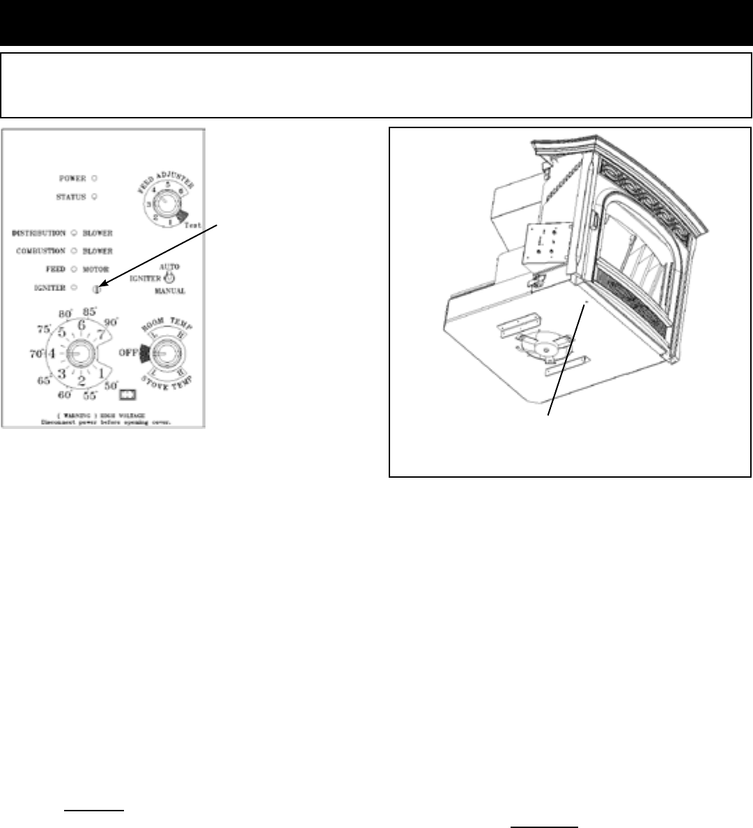
ESP Control
3 Blinks:IndicatesthattheESP(ExhaustSensingProbe)
hasfailed,hasabrokenconnection,orhasgoneoutofrange
toomanytimes.Thisrequiresamanualreset*.
4 Blinks: Can occur only in Room Temp Mode and
indicatesRoom Sensing Probefailedor not installed.Ifa
RoomSensingProbeistheninstalled,thestatuslightwill
automaticallyreset.
NOTE:Unitwillnotstartin"AUTO"withthisstatuserror.
5 Blinks (In Igniter Auto. Mode Only):Indicatesthattheunit
hasfailedtolightwithinthe36minutestartcycle.Toreset-
TurnModeSelectorto"OFF",thenturntoeithermodeagain.)
6 Blinks :Indicatesthatthecontrolhascalculatedpooror
incompletecombustionoccurringformorethan25minutes.
Asixblinkstatusmaybesetifthestoveisallowedtorunout
ofpellets.Toreset,turnmodeselectorto"OFF"thenback
ontothedesiredmode.Iftheunitwasnotoutofpellets,see
Troubleshootingsection,Page33,formoredetails.
* Manual reset-disconnectpowercordforafewseconds
andreconnect.IferrorstilloccurscallyourDealer.
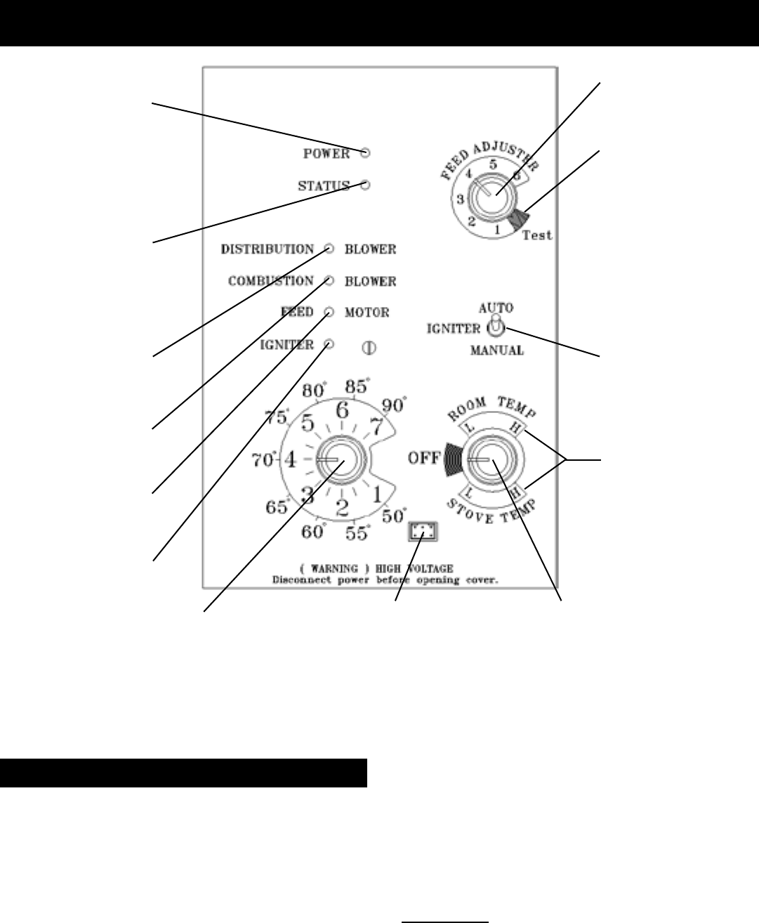
Feed adjuster
Sets the maximum feed
rate
Test
Runs all motors at full
speed for one minute
to check operation.
Afterwards the control
will simulate a minimum
burn with the combustion
blower remaining on
low.
Distribution Blower
speed adjustment
range.
L = low
H = high
Variable speed
anywhere between L
and H; although as the
stove temp. goes up , so
does the L and H scale.
Temp dial
Allows you to adjust the room temperature
setting, in Room Temp Mode, using
the outer scale marked in degrees
Fahrenheit. It also allows you to adjust
the stove temperature setting, while in
Stove Temp Mode, using the inner scale
marked from 1 to 7.
Mode Selector
Allows you to choose between Room
Temp Mode, Stove Temp Mode, or OFF.
Also allows you to vary the distribution
blower speed by turning the knob to the
high or low side of each mode.
Power Light
Indicates power to the
control.
Indicates power to the
feed motor.
Indicates power to
combustion blower
Status Light
Will be lit in either stove
or room temp mode
when pointer is not
within off position band
except after normal shut
down. Blinks to indicate
errors listed below.
Indicates power to
distribution blower.
Dealer Diagnostic Port
For dealer maintenance only.
Requires special DDM monitor
supplied to Harman Dealers
exclusively.
Status light error messages:
Indicates igniter is on.
Igniter switch
Set to appropriate Start-
Up mode.
9
3-90-00674R28_12/13
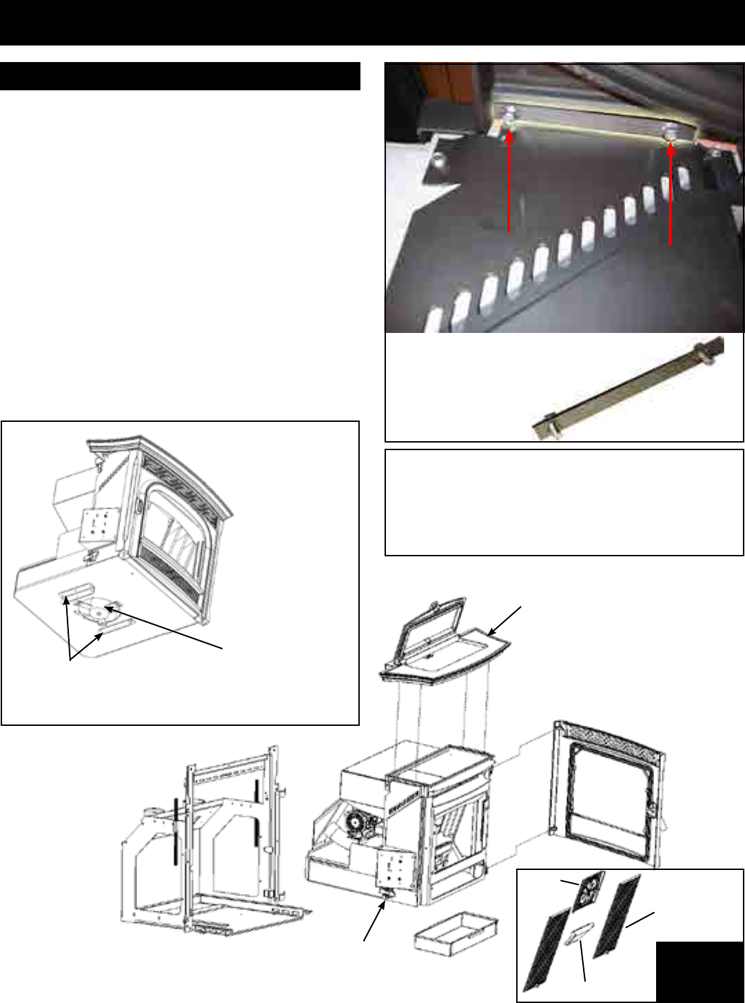
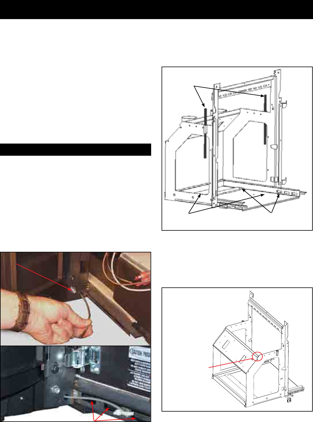
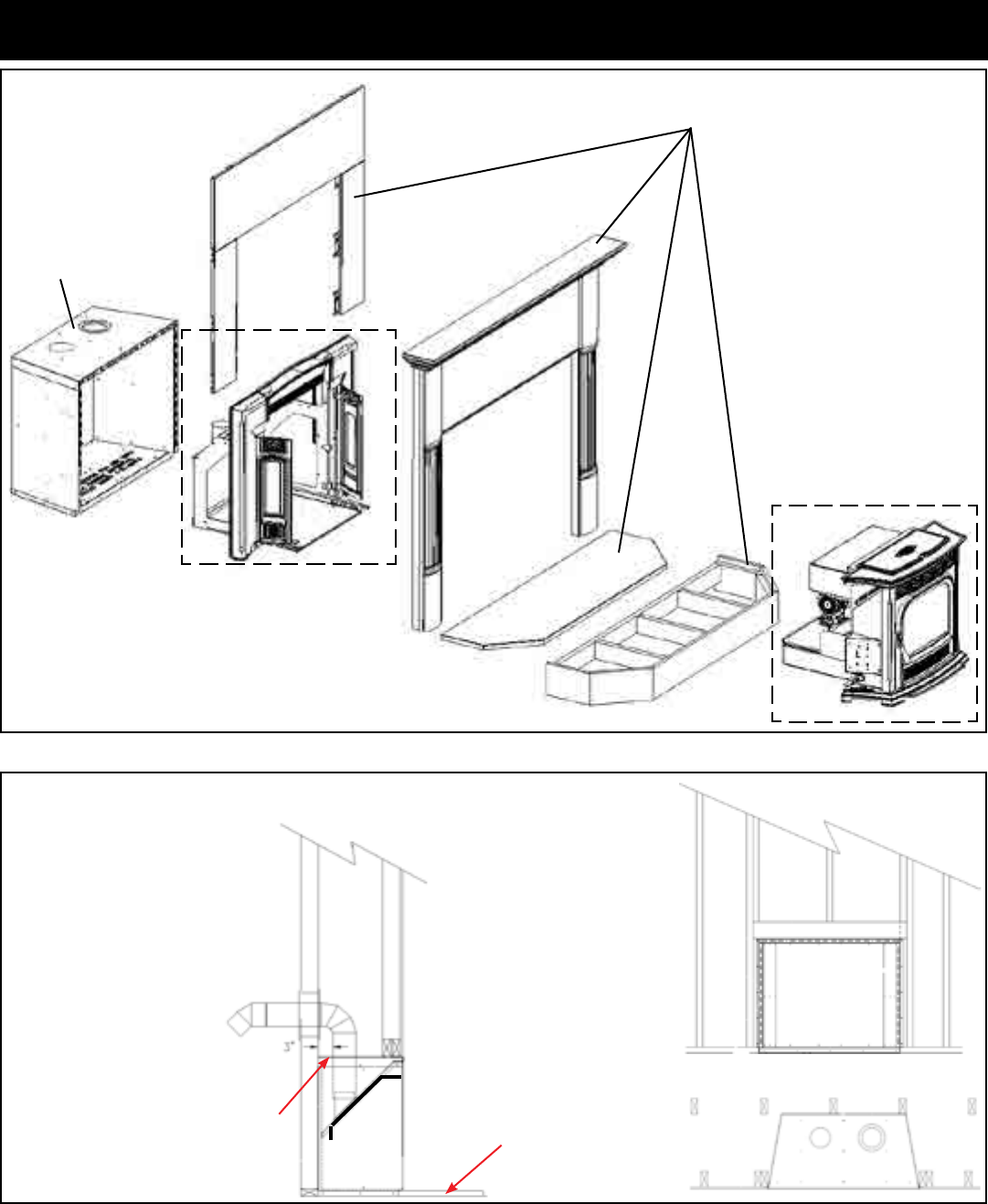
TopandLidAssembly
Center
Medallion
FlameGuide
Heat
Exchanger
Cover
AshPan
(2)SpringLatches
(Oneoneachside) Internal
Cast Iron
(4) pieces
MountingShell
NOTICE:Whenremovingthetopandlidassembly,
rstremovethehopperlidpositionswitchfromits
mounting bracket. Loosen the switch retainer nut,
andallowtheswitchtodropoutofthebracket.Leave
the bracket in place.
Fig.11
Installation
1.Removethetop/lidassemblyandsidepanels.
Note: Removal of the cast hopper lid itself is NOT
necessary or recommended.
Note:Thehopperlidmustbeinthe"OPEN"positionbefore
thetop/lid assemblycan belifted off or reinstalled on the
stovebody.
Thereare(4)1/4-20x1/2"angeheadboltssecuringthe
top/lidassemblytothestovebody.Theycanberemoved
fromtheundersidewitha3/8"socket.
The cast top and lid assembly bolt down bars:
Oneachsideofthestovebody,underneaththecasttop,
are(2)1/4"angeheadbolts.SeeFig.12.
Theseboltspullthecasttopandlidassemblydownontothe
hoppergaskettosealthehopper.
Theyalsoallowforasmallamountoffronttobackadjustment
foralignmentofthetopintothewingpockets.
ProtectorAngles: These angles are designed to
protecttheblowermotorfromdamagewhenplaced
onaatsurface.Becarefulwhereandhowthestove
bodyishandled.
Be careful not
to damage the
distribution blower
located under the
insert. There are
guardsonbothsides
ofthemotortoallow
theinserttorestona
atsurface,however,
extracareshouldbe
taken.
DistributionBlower
Bolts require a
3/8" socket.
(View looking up under the cast top.)
Top bolt down bar
Fig.10
Fig.12
How to Reduce the Weight for Installation
10
3-90-00674R28_12/13
Installation
How to Reduce the Weight for Installation, cont'd
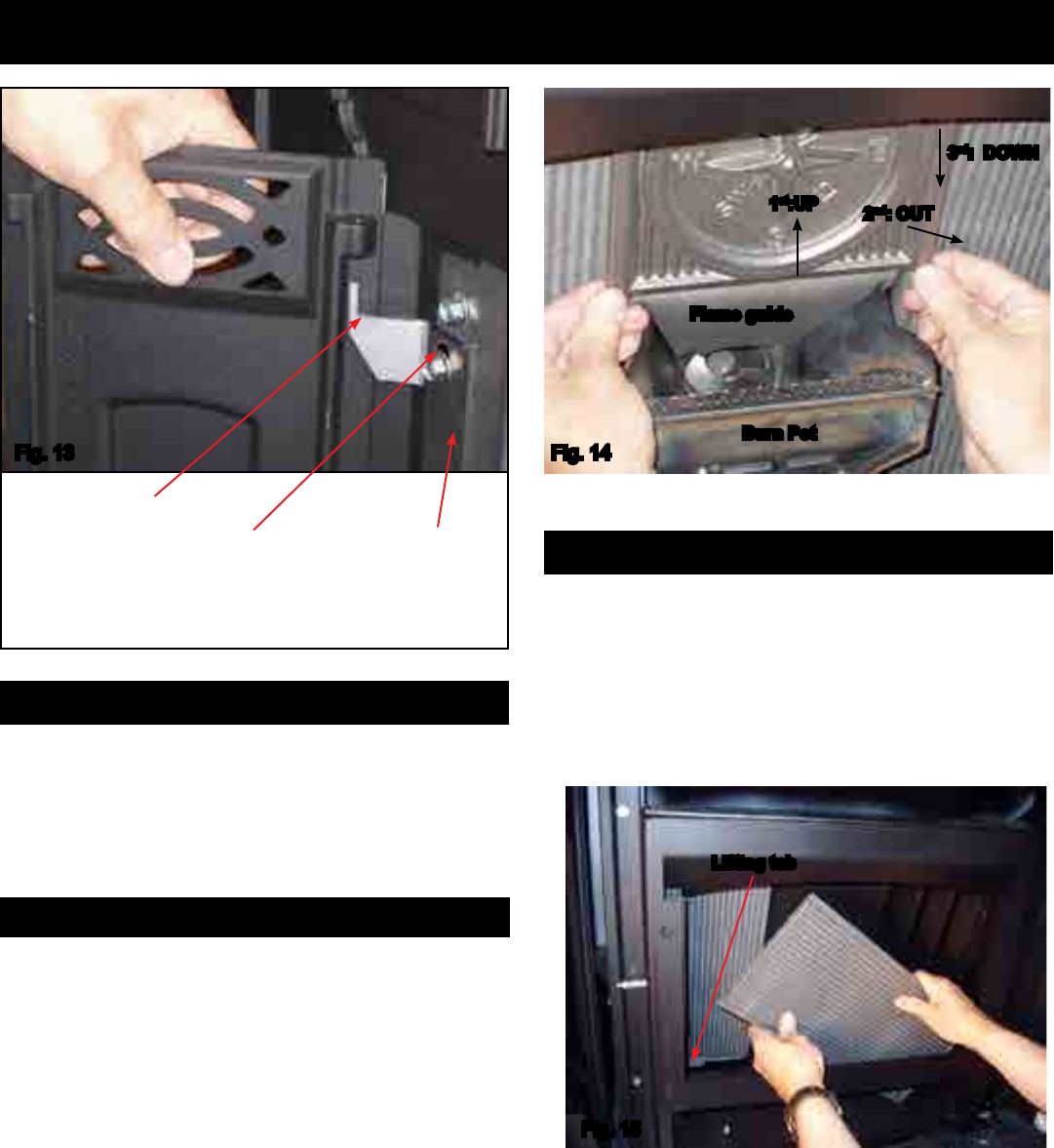
• Liftuponthe2bottomcornersofthemedallionuntilitis
higherthanthetopoftheameguide.Fig.14
• Pullthebottomedgeofthemedallionfrontapproximately
1inch.
• Pulldownwardonthecornersofthemedallionuntilthetop
isreleasedfromthe2retainersthatkeepthetopaligned
wheninplace.
Note:Theheatexchangercoverswilltilttothefrontwhen
thecentermedallionisremoved.
• Remove the heat exchanger cover by lifting it upward
about1/2inchandmovethebottomedgefrontuntilitsits
atonthereboxbottom.
• Rotate the edge of the heat exchanger closest to the
burnpotuntilitisinfrontoftheburnpot.
• Tipthetopoftheheatexchangertowardthemiddleof
theopeninguntilitcanbeliftedupandout.
Flame guide
Burn Pot
3rd: DOWN
1st:UP 2nd: OUT
Fig.14
Lifting tab
Fig.15
Removethecastsidepanelsbyliftingthemupwardoffofthe
hingepins.SeeFig.13.
Removing the Center Medallion
Removing the Heat Exchanger Covers
Laseredhingepinpivot-
ingpoint Upanddownclearance
adjustmentslots.
Castside
panelhinge
Fig.13
2. Removethedoorbyswingingitopenapproximately90°
andliftitupwarduntilitclearsthehingepins.
3. Removetheashpan
4. Removethe(4)internalpiecesofcastiron.SeeFig.14
and15.
11
3-90-00674R28_12/13
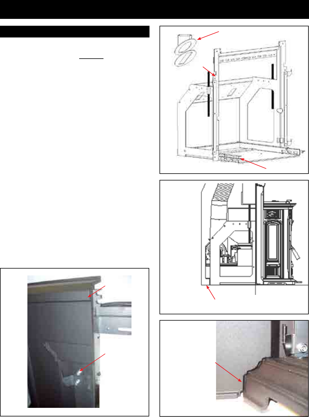
Installation
IMPORTANT: Themountingframe/surroundassemblyand
uepipingisthemostcriticalpartoftheinstallationandmust
bedonecorrectlyandinstalledsecurely.
1. Choosethechimneycongurationthatisbestsuitedfor
theinstallation.Seeventingsection.Page21
Note:If100%outsideairisdesiredorrequired,theoutside
airoptionwillneedtobeinstalledonthestovesbody.(See
instructionsincludedwithoutsideairkit(part#1-00-674080.)
SeePage22.
2. Makesuretheunitwilltintothereplaceopening.When
installinginsmallerreplaces,testtthemountingframe
intotherebox.Note:Theunitoverhangstotherear.See
Fig.17
3.Installing the 3 piece cast surround:Installtheleftand
rightcastsidestothemountingframeusingthe1/4-20x
3/8boltssupplied.Install(4)1/4-20x3/4"setscrewsinto
thetopwing.Theninstallthetopwingontotheframeusing
the(4)1/4-20nuts.Theleftandrightsideshouldbedone
beforethecentersectionisinstalled.Makesurethebolts
areloose.Donotremovethesidepanelhinges.Theleft
andrightsidewingsshouldbestandingupalignedwith
thesideofthemountingframeandslidinwardtowards
thecenter.Note:Thewingsmountontherearsidebelow
thenotchandonthefrontsideabovethenotch.SeeFig.
16&18.Slidethecastashlipontotheframeandcheck
tomakesureitcangoagainsttheropedframerailsand
tsintothepocketsontheleftandrightcastsides.See
Fig.19.
Installthecentersection.
4. If the wing extension is required, it should be installed
next.
Beginning Installation
Fig.18
Cast in front of
the frame. Use
(1)1/4-20 x 3/8
flange bolt from
therear.
Cast behind the
mounting frame
flange. Use (2)
1/4-20x5/8ange
bolts and nuts
with bolts from
thefront.
NOTE:Thestovebodyextendsthroughthemountingframein
therearapproximately2".
Fig.17
Slidetheashlipcasting
intotheframe,making
certain the ash lip is
sittingonthesliderails
on either side. With
the ash lip in place,
adjust the surround
sides so there is an
even gap where the
ash lip extends into
thesurroundsideand
tighten.
Fig.19
3"OutsideAirstartercollar
Fig.16
Notch
Ashlipsliderails
12
3-90-00674R28_12/13
Installation
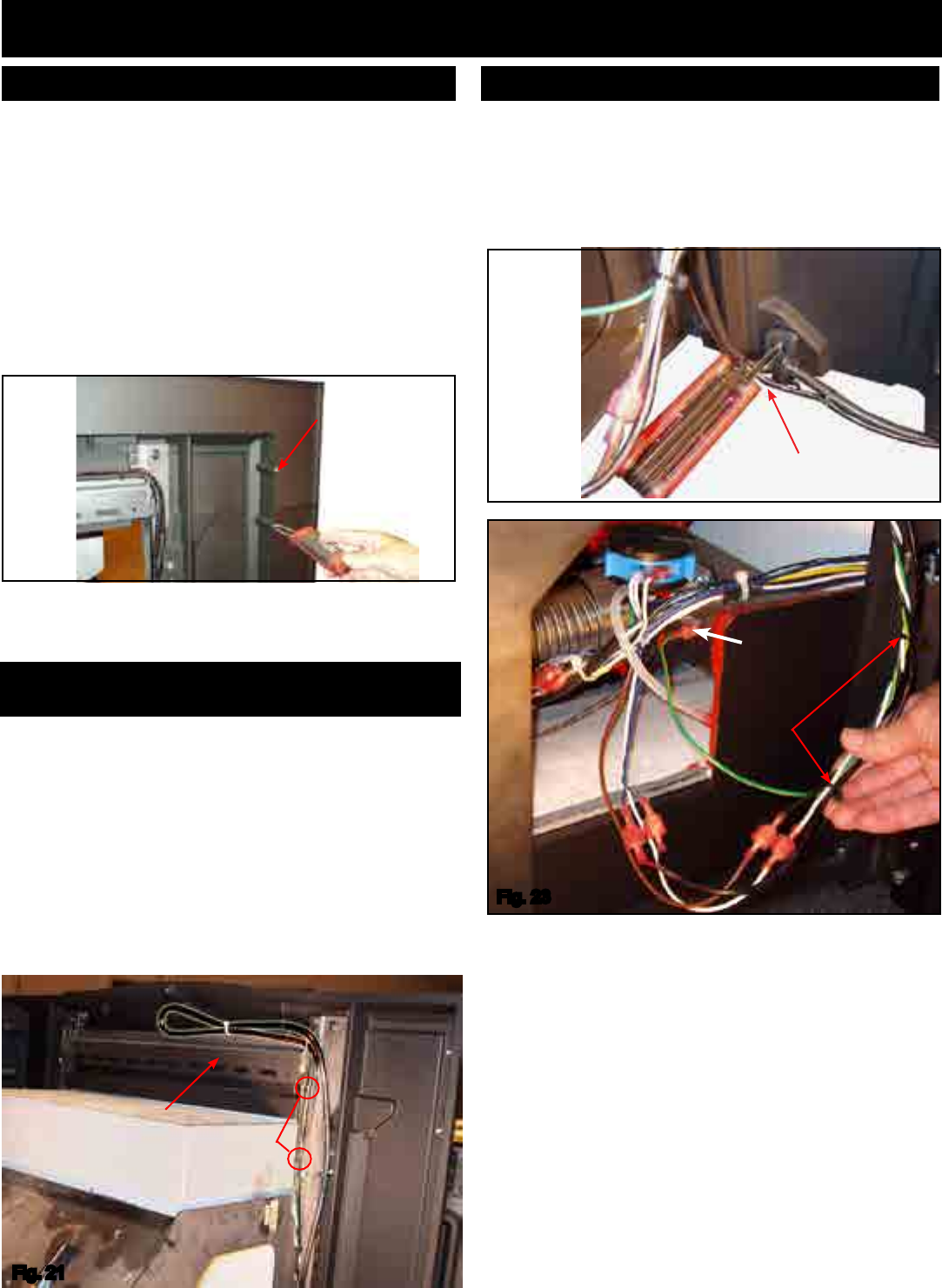
5. Thepowercordcanbeinstalledexitingtheleft(standard)
orrightsideofthesurround.Ifarightsidecordisdesired,
followtheinstructionsbelow.
Thecordislocatedontheleftside,standardfromHarman.
(Seeg21.)
Toroutethecordtotherightside:
Cutthewire-tiesloopingthecordtotheleft
Re-routethecordalongthetopofthesteelangleanddown
therightside.
Re-tie(notsuppliedbyHarman)thewirethroughthenotches
providedinthemountingframe.Thendowntherightsiderail.
Donotremoveormovethecordretainer,itismadetoreach
boththerightandleftsides.
Nothing can extend
beyond this face to
the back side.
DO
NOT
CUT.
Withthethreewingpiecescompleted,thecordretainermust
beboltedtothebottomrearofthewing.Eitherleftexit(shown
ing.22)orrightexit.
Atthebottomrearedgeoftherightandleftwingthereisa
smallradiusindentforthecordtoexitbetweenthewingand
thereplaceface.
6. Youmustnowdecidewhethertoinstalltheroomsensor
asawallsensororasareturnairsensor.Harmanhighly
recommendsthattheroomsensorbeinstalled.Ifyouare
installingtheroomsensorasawallsensor,thelongblack
2wirecablemustbewire-tiedtothepowercord.Thiswire
islongenoughtoreachtheendofthepowercordsothe
installercanreachpastthehearthtothelocationwhere
theextensionwire(18/2thermostatwire,notsuppliedby
Harman)canbesplicedtogotothewalllocationchosen
fortheroomsensor.
Fig.21
Fig.22
Theoptionalwingextensionismadeforreplaceopenings
which are larger than the cast wing. The standard wing
extensionis48"wideby34"high.
Customsizedwingextensionscanbepurchasedfromyour
dealer,foranyreplaceopeningslargerthanthestandard
wingextensionarea.
Theseoptionalwingextensionswillhavea1/2inchreturn
bendasshowning.20.Customoversizedwingextensions
with a radius top can be ordered with a radius of your
choosing.TheseradiuswingextensionsWILLNOThavea
returnbend,althoughtheywillbemadeofthickermetalto
reducewarpage.
(5/32"allenwrench)
Optional Wing Extension
Changing the cord exit location from the left
side to the right side:
Fig.20
1/4-20x3/8
buttonheadbolts
(5/32"allen
wrench)
Connecting the cord retainer to the wing
Ground
wire-ties
Fig.23
13
3-90-00674R28_12/13
Installation
7. If the room sensor is used as a return air sensor
ratherthanaroomthermostat/sensor,theblackcable
willnotbeused.Theroomsensoritself(grayorblack
cablewithblackandredwires)willbeconnectedto
thebluetwistedwiresfromthecontrolboard.
Note:Thestovebodymustbeabletoslideoutofthe
shelltothelimitofthepowercordwiresforcleaningand
service.Therefore,iftheroomsensorisconnectedas
areturnairsensor,thewireshouldbeconnectedlong
enoughtoallowthis,butnottoolongthatitwouldget
tangledorpinchedanywhere.
Notice: The male/female connections between the
mountingshellandthestovebodyshouldalwaysbe
maintained.Wirenutortapedsplicesshouldneverbe
used.
Insertthesensorendofthewirefromtherearofthe
mountingframethroughtheholeasshowning.24.
Wire-tiethesensorendsothatthesensingtipisinthe
middleofthefrontreturnairopening.SeeFig.25.
Wire-tiethesensorwiretotheinsideofthemounting
frame up to the cord grounding location. Follow the
power wiring to where you make the male/female
terminalconnectiontothetwistedbluewires.
Thereare(2)crimp-onconnectorsinthehardwarepack
thatmustbeinstalledontheinternalendsoftheroom
sensorwires.
8.Install the (4) 3/8-16 x 1" leveling bolts into the
threadedholesinthebottompanofthemounting
shell. The front two leveling bolts may not be
necessary, but the back two will need to be used
tolevelthewingsothatitisushwiththereplace
face.SeeFig.26
Connecting the room sensor as a return air sensor
9.Installthecompletedframe/surroundassemblyinto
thereboxandlevel/plumbthewingtothereplace
faceusingthelevelingboltsasjacks.
Ifneeded,theinstalledHCS¼-20x1Z5boltcanbe
usedtoadjustthesquarenessofthestovebodyinthe
cage.
3/8x16tapped
levelingboltholes
Fig.26
1/2"threaded
wedgingrods
(5)boltdownholes
SideReturnAirHoles
Fig.25
Fig.24
Adjustbolthere
14
3-90-00674R28_12/13
Installation
Therearethreedifferentuepipestubsavailable.
1. Theunitcomesstandardwiththelargest,forusewith4”
stainlesssteelexpipe.
2. Part#1-00-674040isforusewith4”PLventstarterpipe.
3. Part#1-00-674039isforusewith3”PLventstarterpipe
andalsoforusewith3”aluminumexductforoutsideair
connections.
Theuestubassemblybaseisaroundplatewhichallowsit
toswiveltoallowtheuepipetoexitthemountingframein
otherpositionsratherthanstraightup.Seeg.28.
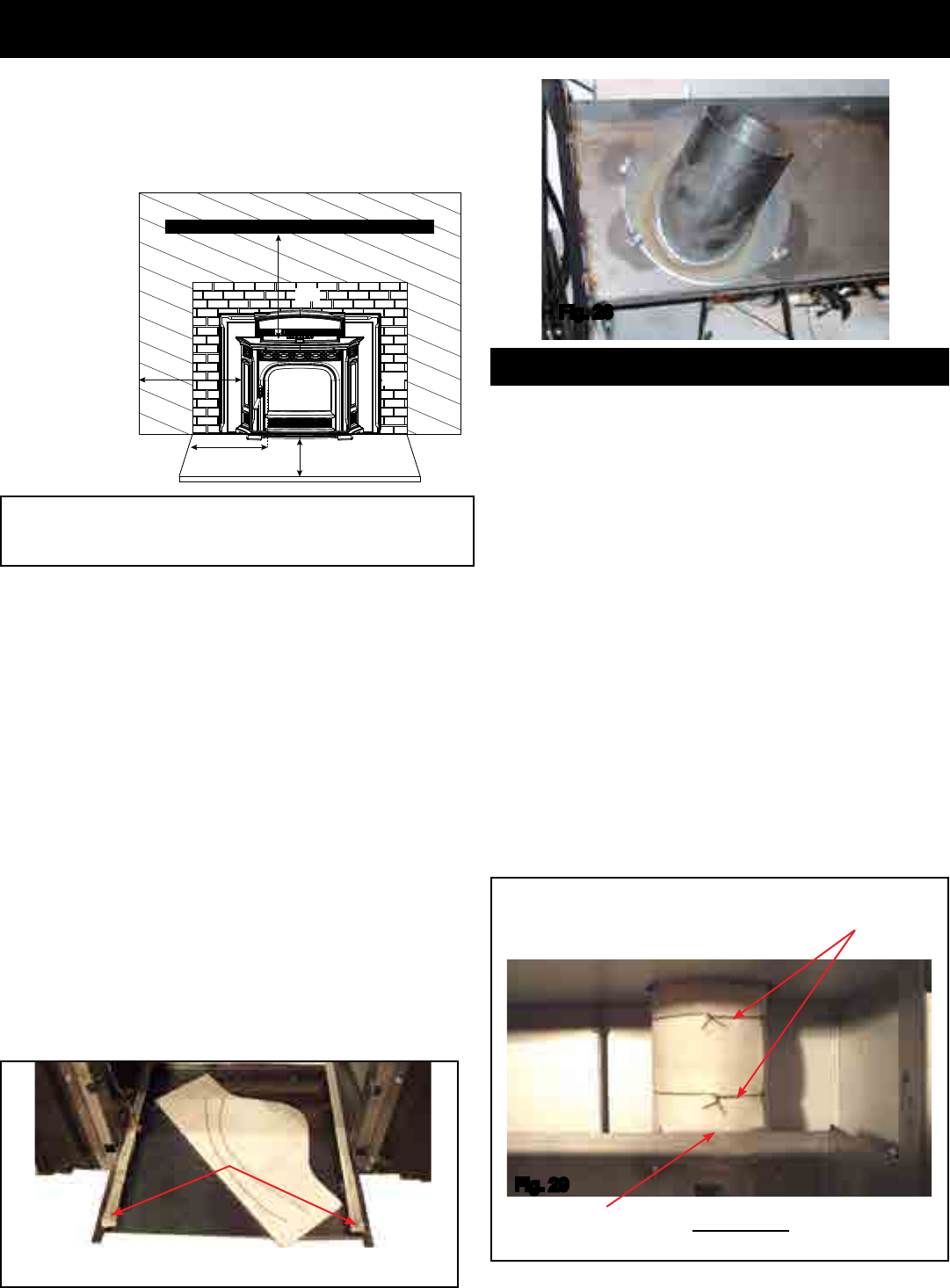
14. Installtheuepipeinsulationwrap.See Fig. 27.This
ceramicinsulationisprecuttoformaroundtheuepipe
stub,toreduceheattransferintotheareaaroundtherear
ofthehopperandmotorarea.This insulation must be
installed in all congurations, even if a rear discharge
is used. SeeFig.29.
Fig.28
A=tosidewall
B=to12"mantel
C=to3/4"trim
D=to3/4"trim
E=oorprotection
Fig.27
Ash lip
mounting
rails
Pre-cutceramicinsulationand(2)piecesoftiewire.
Twisted tie wire
Withlargeruepipesthisbottomedgeoftheinsulationwill
needtobetrimmedtocompletethewrap.
Thispictureshowsthecompletedinsulation
wrapped around the flue pipe from the
mountingframeupward.
Fig.29
Flue Pipe Stub Assembly
*Floorprotectionmustbeusedfromhearthopeningto6"
(152mm)infrontofdoorglassand6"(152mm)toeachside
ofthestovebodytoprotectcombustiblesfromhotashes.A
minimumsizewillbe16.5"deepby30"wideandbemade
ofanon-combustiblematerialormeetULapproval.
10. Testtthecastashlip(Seeg.25)ontheshellframe
mountingrails.Theashlipshouldslideon theseside
railswithoutliftingupwardoffoftherailsastheashlipis
slidinward.Asmallclearanceofabout1/16"isanideal
spacebetweenthelegsoftheashlipandthehearth.
Thiscastashlipisadecorativepartthatdoesnotand
shouldnotsupportanyweight.
11. Tightenthe(2)1/2"threadedrodsupagainstthelintel
ofthereplaceopening.Itisalsorecommendedtouse
someformofanchoringscrewsthroughthebottomofthe
shellintothehearth.Thereareupto5holesprovided.
Note:Itisagoodideatochecktheashlipagain.The
framemayhaveshiftedwhenthenalanchoringwas
completed.Seeg.26.
12. Completetheuepiping,andoutsideairpiping,ifused.
Makesurethedamperareaissealed.
WARNING! DO NOT CONNECT THIS UNIT TO ANY AIR
DISTRIBUTION DUCT OR SYSTEM.
13. Ifarearexituecongurationisused,withorwithout
outsideair,makesuretheuepipeterminationclearances
arefollowedasperthemanufacturersrecommendations.
12” (305mm) Mantel
B
A
EE
C
D
CLEARANCES: A B C D E
From Insert Body: 10” 12” 0”* 6” 6" (From Glass)
*3/4” trim, zero clearance to cast surround
15
3-90-00674R28_12/13
Fig.32
Installation
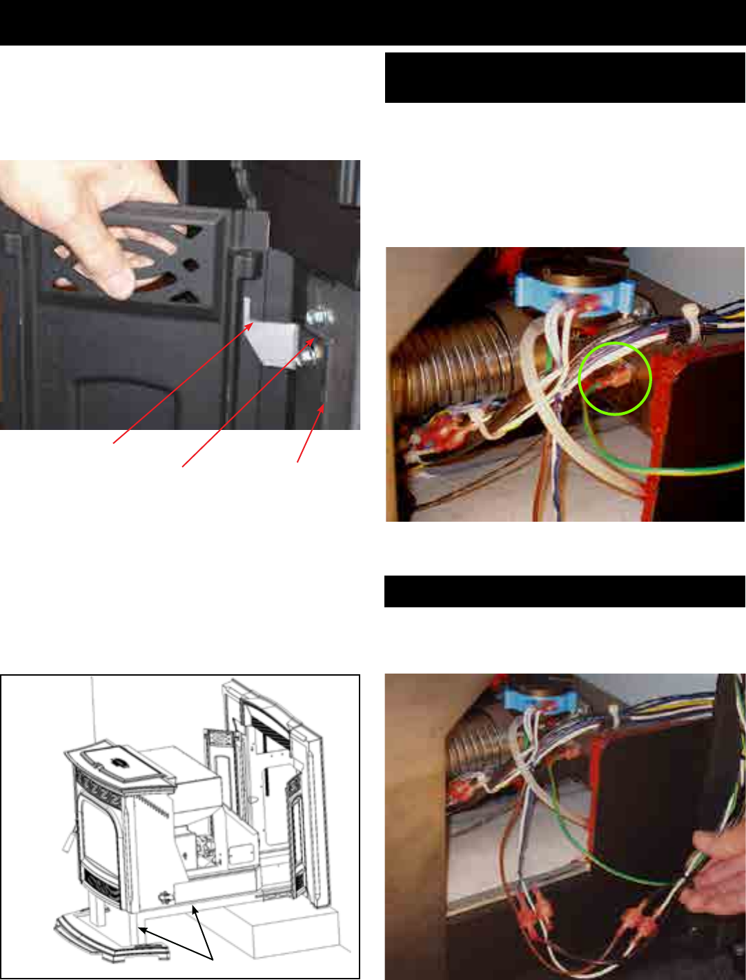
The green wire with a female terminal is the stove body
ground.SeeFig.32
On the combustion air inlet box there is a male terminal
ground.
If service is performed on this stove, this ground
connection must be the rst one on and the last one off.
Fig.33
15. Installthecastsidepanelsbyslidingthemdownover
thelaseredhingepin.Note:Checkforrotationalswing,
butnishwiththemintheopenposition.Thecastside
panels may need adjustment after the stove body is
latchedintoplaceandthefrontdoorisclosed.
Connecting the power cord
Thewhitefromthemountingframeconnectstothewhiteof
theinsertbody.Theblackfromthemountingframeconnects
tothebrownoftheinsertbody.
16. Placethestovebodyonthemountingshellgasketedrails
andinsertthebodyintotheopeningfarenoughthatit
can'ttipout.Note:Aservicerailkit(Part#1-00-08007),
orapairof2x4'ssupportedinfrontofthehearthwill
makethisjobeasier.SeeFig.31.
17. Completethefollowingelectricalconnections(CAUTION:
Disconnectthe powercord.)There are5 connections
thatmustbecompleted.SeeFig.33&34.
Fig.30
Laseredhingepin
pivotingpoint Upanddownclearance
adjustmentslots.
Castsidepanel
hinge
Fig.31 2x4
Connecting the ground from the wing to the
stove body
16
3-90-00674R28_12/13
Installation
• Connectingtheroomsensortothebluetwistedwiresfrom
thecontrolboard:
• (2)3/16inchmaleterminalsareprovidedfortheendsof
theroomsensorwires.
• They will mate with the female terminals on the blue
twistedwires.
• Theseconnectionsare“notpolarityspecic.”
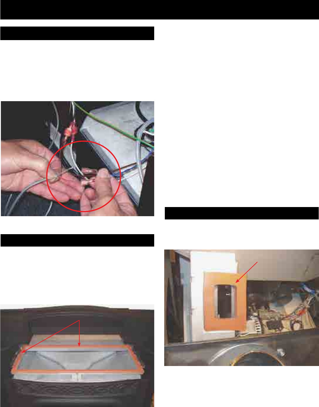
• Inspectthesiliconespongehoppertotopsealgasket.
• Lookfortearsorareaswherethegasketmaynotseal
properlytothebottomofthecasttop.Thisonlyneedsto
bedonewhenthetopisremoved.ThisisNOTnecessary
ifthecasttopisnotremoved.(Notpartofanymonthly,
semi-annualorannualmaintenance.)
Fig.34
Everytimetheunitispulledoutofthemountingframe,the
orangehightemperaturedockinggasketshouldbeinspected.
Checkfortearsorsignsthatthegasketisnotsealingproperly.
19. Inspectthesiliconespongegasketonthetopedgeof
thehopper.
• Ifitisokay,putthecasttop/hopperlidassembly(seeFig.
35)intoplaceoverthehopper.
• Makesurethehopperlidisopentoinstallthetop,then
closeittokeepfromgettingpinchedincasethelidfalls
unexpectedly.
• Insert the (4) 1/4-20 x 1/2 ange head bolts into the
mountingholebutdonottightenthem.Seepage9,g.
12.
20. "Test"theunitwiththestovebodypulledout.Thiswill
allowyoutoseethemotorsinoperation.
• Turnthecontroltothe"OFF"position.
• Plugtheunitintoa120VAC,60Hzoutlet.
• Turnthecontrolto"test".Allofthemotorsshouldoperate
atfullvoltagefor60seconds.
Note:Thedoormustbeclosedforthefeedmotortooperate.
• Withthe"Test"completed,turnthefeedadjusteroffof
test,andunplugtheunit.
21. Inspecttheuedockinggasket.SeeFig.36.
18. Installthefrontdoor.Checkthelatchandgasketing.
Connecting the Room Sensor
Hopper Seal
Fig.35
Hoppersealgasket(grayororange)
Docking Gasket
Fig.36
DockingGasket
17
3-90-00674R28_12/13
Installation
• Thestovebodymustbepulledoutofthemountingframe
severalinchestoinstallthecastsidepanels.
• Slidethecastsidepaneldownoverthehingepins.
• Slidethestovebodyinandlatchintoplace.
Note:Thecastsidepanelsmustbeleftintheopenposition
toallowaccesstothelatches.
• Slidetheashlipintoplace.(Thiswouldbeinwarduntilthe
rearofthecastirontouchesthemountingframefront.)
• Closethecastsidepanels.
• Check the gap alignment and the top and bottom gap
spacing.
• Thetopandbottomspacingcanbeadjustedbyloosening
the 3 bolts and sliding the hinge up or down until the
spacingsuits.
• Withthefrontdoorclosedandlatched,checkthevertical
space alignment. The only method of changing or
adjustingthisgapisbybending(slightly)thehingeangle.
Seeg.39.
• Duetotheuseofallcastironparts,somesmallamountsof
misalignmentareexpected.Sincesomepartsareangled
andsomehaveroundededges,thismisalignmentisvery
seldomnoticeable.
• Itisvery important thatthecast side panelsopenand
closefreelyforcontrolboardaccess.
22. Slidethestovebodyintothemountingframe.
• Note:Thetwospringlatchesonthebottom
rightandleftsideofthebodymustbeintheproper
positiontoenterthelatchholes.(Seeg.37).
• Latchthe(2)springlatchesintoplace.
23. Shiftthecasttop/hopperlidassemblyinwardasfaras
possibletoachieveaparalleltwiththesurroundsides.
SeeFig.39.Tightenthecasttop/hopperlidassembly
boltswitha3/8"socket.Seepage9,Fig.12.
24. Installandadjustthesidepanelmagnets.
• Inthehardwarepackare(2)magnets,(2)spacersand
(2)10-32x11/4"boltsandnuts.
• Boltthemagnetsthroughtheholesprovidedinthecast
ashlip.
Important:Thespacermustbeontopofthehole,themagnet
ontopofthespacer,withtheboltgoing,down,throughthe
hole,withthenutatthebottom,undertheashlip.Seeg.38.
25. Checkthetofthecastashliptomakesurethatitcan
beslidinandouteasily.Thecastashlipcanremainin
placeatthistime.Note:Thecastsidepanelhingescan
bemovedupwardifnecessarytogainclearanceforthe
castashlip.
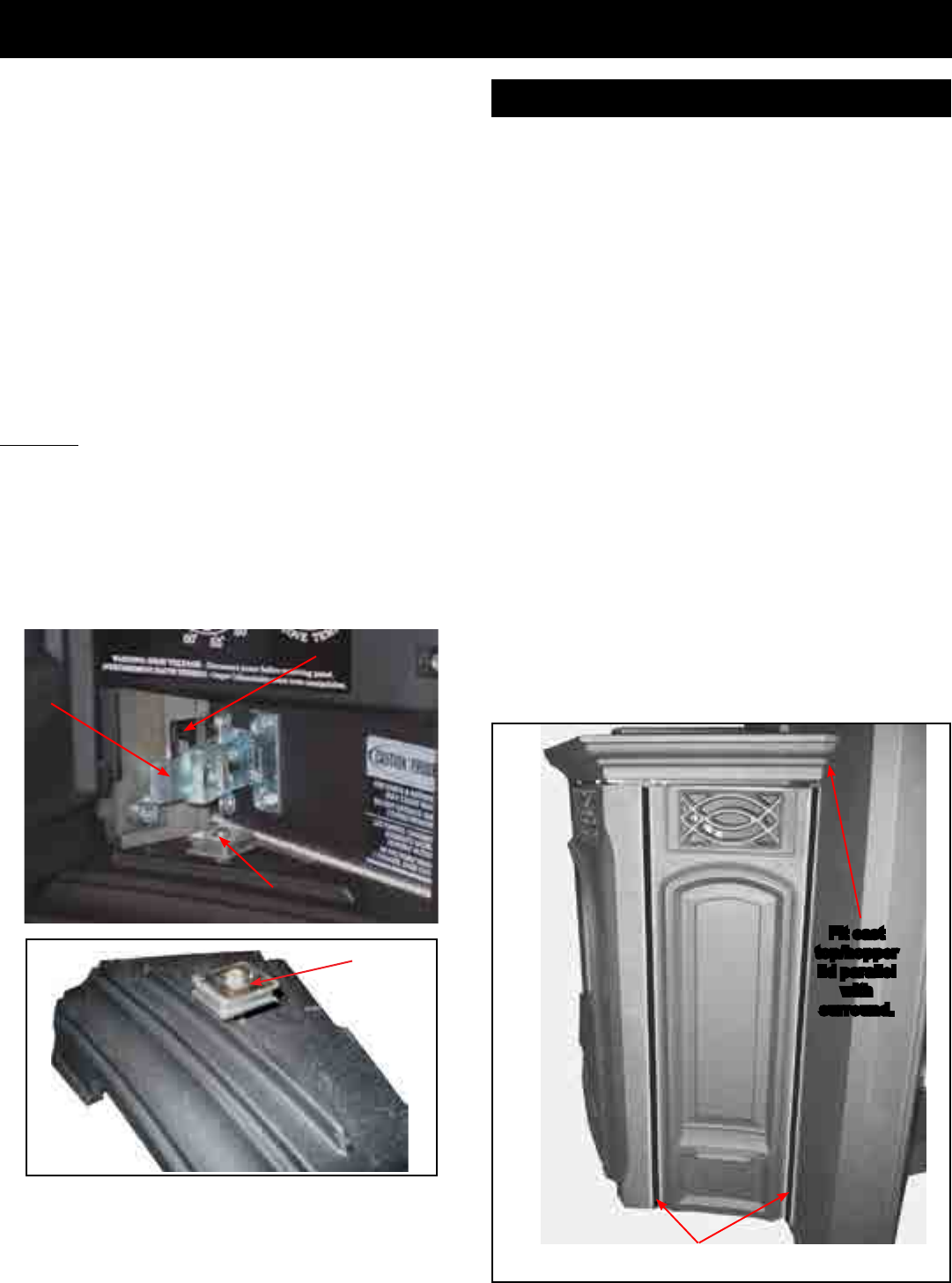
Fig.39 Sidepanelgap
Fit cast
top/hopper
lid parallel
with
surround.
Cast Side Panel Installation
Fig.38
Magnet
Fig.37
Spring Latch
Latch Hole
Magnet
18
3-90-00674R28_12/13
Always disconnect the power cord before the unit is
pulled from the mounting frame.
Asyoucansee,thecontrolboardiseasilyaccessiblefrom
therearwiththebodypulledoutoftheframe,evenifitis
onlypulledoutseveralinches.
• Alwaysinspectthewiring harness ofthe11pinsocket
(large white flat plug where all of the power wires
terminate.)
• Alwaysinspectthewiringharnesswherethewirestransfer
fromthecontroltotherearinsideofthebody.
• Makesuretherearenowornorfrayedareas.
Installation
Log Set Option
Installthelogbracketwiththetwothumbscrewsprovided.
Centertheloginthereboxopeningwiththebottomfront
edgeoverthethumbscrews.Thelogbranchtipsonlyrest
onthebracketarmsforeasyinstallationandremoval.
IMPORTANT NOTE: BEFORE CLEANING THE HEAT
EXCHANGERS, THE LOG AND THE LOG BRACKET
MUST BE REMOVED.
• Do not allow pellets or sawdust to build up on the
hopper lip.
• Inspect the hopper lid gasket for damage. A good
hopper lid seal is very important for proper operation.
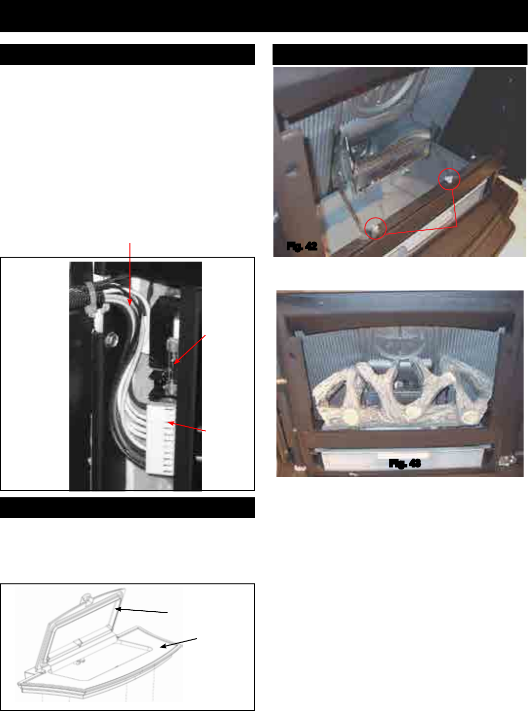
Fig.42
Thumb
Screws
Wiring
6 amp
glass
fuse
Inspect the wiring harness transition area: This is the area
that comes closest to the mounting frame as the unit is slid
in and out of the frame.
11 pin
socket
on rear
of control
board
REMINDERS
Fig. 43
Hopperlidfoam
gaskets
CastTop
Fig.41
Fig.40
19
3-90-00674R28_12/13
Theseunitsarepre-testedatthefactorywithexactly120VAC,
60Hz.Theyarecheckedandadjustedforreboxtightness,
gasketleakage,motoroperationandigniteroperation.The
stoveisthenfactorysetatahighadjustment.NOTE: Low
draft adjustment may be required. The factory low draft
setting may not be correct for the unit's permanent
installation conditions.
ThecontrolboardontheAccentraInsertisequippedwitha
lowdraftadjustmentport.Locatedonthecontrolfacejust
totherightoftheigniterlight.SeeFigure44.Thisvoltage
adjustmentisprovidedtoallowtheunittobeadjustedforthe
householdvoltagewheretheunitisgoingtobeinpermanent
operation.NOTE:Thelinevoltagevariesfromareatoarea
andoftenhometohome.
Thelowdraftvoltageshouldbeadjustedtoachievethemost
efcient burn on low burn or "maintenance". This voltage
adjustment allows the installer to change the low voltage
set point approximately 15 volts. This adjustment should
bedonebytheinstallerduringsetupbecauseadraftmeter
readingisrequired toinsurepropersetup.
Iftheunitisnotadjustedproperly,itdoesnotcauseasafety
concern.Iftheunitisadjustedtoohigh,onlyefciencyislost.
Iftheunitisadjustedtoolow,thelowdraftpressureswitch
willnotallowthefeedermotorortheignitertooperate.
Aftertheinstallationiscompleted,butbeforetherstreislit,checkandrecordthe
highandlowdraftreadings.
Asimpledrafttestshouldbeperformedaftercompletingthe
uepipeinstallation.Torecordtheresultsforfuturereference:
1. Plugunitintoa120VAC,60Hzoutlet.
2. Closethehopperlidandfrontviewdoor.Neitherpellets
orarearerequiredforthistest.
3. Withthemodeselectorinthe"OFF"position,turnthefeed
adjusterto"TEST".
4. Record the high draft_____in. W.C. (Normal is -.45 to
-.55)ThecontrolwillbeontheHighDraftforatotalof1
minute.
5. After1minute,thecombustionmotorwillgodowntolow
draft and the distribution blower will go on high.Allow
approximately 15 seconds to pass for the combustion
motortoslowbeforecheckingthelowdraft.
6. Ifthelowdraftisbetween.30and.35,recordthereading
_____in.W.C.Ifthereadingishigher,slowlyturnthe
setscrewcounter-clockwiseuntilthedraftlowers.Ifthe
readingislower,veryslowlyturnthesetscrewclockwise
untilthedraftincreases.
NOTE: In some cases, the draft may not go as low as .30
even with the set screw completely counter-clockwise.
Combustion Motor
Speed Control
Low draft only set
point.
The small straight
screwdriver slot is
plastic; therefore,
the unit can be
adjusted while in
operation.
Fig.44
Draft Meter bolt hole location
Theheadoftheplugboltcanbeaccessedthroughthebottom
distributionairinletwiththecastashlipremoved.
Fig.45
Low Draft Voltage Adjustment

20
3-90-00674R28_12/13
Mobile Home Installation
CAUTION
THE STOVE IS HOT WHILE IN OPERATION.
KEEP CHILDREN, CLOTHING AND FURNITURE AWAY.
CONTACT MAY CAUSE SKIN BURNS.
WARNING
KEEP COMBUSTIBLE MATERIALS SUCH AS GRASS,
LEAVES, ETC. AT LEAST 3 FEET AWAY FROM THE
POINT DIRECTLY UNDER THE VENT TERMINATION.
WheninstallingandoperatingyourHarmanAccentraInsert,
respect basic safety standards. Read these instructions
carefullybeforeyouattempttoinstalloroperatetheAccentra
Insert.Failuretodosomayresultindamagetopropertyor
personalinjuryandmayvoidtheproductwarranty.
Consultwithyourlocalbuildingcodeagencyandinsurance
representativebeforeyoubeginyourinstallationtoensure
compliancewithlocalcodes,includingtheneedforpermits
andfollow-upinspections.
CAUTION: This appliance must be vented to the outside.
Duetohightemperatures,thisstoveshouldbeplacedoutof
trafcandawayfromfurnitureanddraperies.
Childrenandadultsshouldbealertedtothehazardsofhigh
surfacetemperaturesandshouldstayawaytoavoidburn
toskinand/orclothing.
Youngchildrenshouldbecarefullysupervisedwhentheyare
inthesameroomasthestove.
Clothingandotherammablematerialsshouldnotbeplaced
onornearthisstove.
Installation and repair of this stove should be done by a
qualiedserviceperson.Theapplianceshouldbeinspected
beforeuseandatleastannuallybyaqualiedserviceperson.
More frequent cleaning will be required. It is imperative
that control compartments, burners, and circulating air
passagewaysofthisstovebekeptclean.
Safety Reminders
Mobile Home Installation
Mobile home installation should be done in accordance
with the Manufactured Home and Safety Standard (HUD),
CFR 3280, Part 24.
When installing theAccentra in a mobile home several
requirementsmustbefollowed:
1. Theunitmustbe bolted tothe oor.This can bedone
with1/4"lagscrewsthroughthe5holesin the base
plateshowninFig.26.
2. The unit must also be connected to outside air. See
page 22.All mobile home installations require the use
ofoutsideair,thiswillincreasetheheatingefciencyof
theunitandkeepitfromsufferinganyeffectsassociated
withroomairstarvationsuchaspoorcombustionandor
erraticoperation.Periodicallychecktheairinletforany
obstructionssuchassnoworicebuildup.
Kitchen exhaust fans, clothes dryers and other similar
devices may cause improper operation of the pellet
stove, if, while in use, it keeps the room in a negative
pressure,thusallowingpipejoints,notcompletelysealed,
toleakexhaustintotheroom.Besuretoallowadequate
ventilationwhileusingsuchappliances
3. Floorprotectionandclearancesmustbefollowed.Floor
protection and clearances to combustibles must be
followed as per installation instructions for the stove.
Clearancesmayonlybereducedbymeansapprovedby
theregulatoryauthority.
4. Unitmustbegroundedtothemetalframeofthemobile
home.
5. Smokealarmsandsmokedetectorsarerecommended
tobeusedwithwoodandbiomassfueledstoves.When
openingthereboxdoorsomeexhaustmayescapeinto
the room and set off the alarm. If this should happen
ventilate the room to remove the smoke and reset the
alarm,ifthealarmwouldgooffwhennoonewasworking
withthe stoveventilate the roomand have yourhome
checkedtondthesourceoftheleak.
CAUTION
THE STRUCTURAL INTEGRITY OF THE MOBILE
HOME FLOOR, WALL, AND CEILING/ROOF MUST BE
MAINTAINED.
WARNING
MOBILE/MANUFACTURED HOME GUIDELINES DO
NOT ALLOW INSTALLATION IN A SLEEPING ROOM.
WARNING
USE OF IMPROPER FUELS, FIRE STARTERS OR
ALTERING THE STOVE FOR HIGHER HEAT OUTPUT
MAY CAUSE DAMAGE TO THE STOVE AND COULD
RESULT IN A HOUSE FIRE. USE ONLY APPROVED
FUELS AND OPERATION GUIDELINES
21
3-90-00674R28_12/13
A combustion blower is used to extract the combustion
gasesfromtherebox.Thiscausesanegativepressurein
thereboxandapositivepressureintheventingsystemas
showning.46.Thelongertheventpipeandmoreelbows
usedinthesystem,thegreatertheowresistance.
The recommended maximum flue lengths for the
Accentra Insert are as follows:
4" Stainless Steel Flex: 30 Lineal ft. Vertical*
4" PL Vent Pipe:
4" Pl Vent Pipe: 30 Lineal ft. Vertical*
4" Pl Vent Pipe: 14 ft. Vertical w/1-90° and 12 lineal ft. horizontal*
If additional 4" PL Vent ttings are required, the overall
length must be reduced by:
Vertical 90° or T: 2.5'
Vertical 45°: 1.5'
Horizontal 90° or : 5.0'
Horizontal 45°: 2.5'
3" PL Vent Pipe:
20 Lineal ft. vertical*
8 Lineal ft. vertical w/1-90° & 8 lineal ft. horizontal*
If additional 3" PL Vent ttings are required, the overall
length must be reduced by:
Vertical 90° or T: 2.0'
Vertical 45°: 1.0'
Horizontal 90° or T: 4.0'
Horizontal 45°: 2.0'
* Long runs of ex or PL vent pipe installed directly vertical from the ue
stub may require more frequent cleaning due to y ash falling off inside
and collecting directly above the combustion blower outlet.
Any use of horizontal venting will require more frequent cleaning. It is the
responsibility of the installer to make sure the entire ue conguration is
accessible for cleaning.
4" stainless steel ex vent piping is only allowed for use
in masonry replaces and chimneys or factory built wood
burningreplaceswithclassAmetalchimneys.Allpelletvent
pipemustbesecuredtogethereitherbymeansprovidedby
pipemanufacturerorby3screwsateachjoint.
Venting
Use only the specied venting components. Use of any
other components will void the product warranty and
may pose a hazard.
Do Not Install A Flue Damper In The Exhaust Venting
System Of This Appliance.
DO NOT CONNECT THIS UNIT TO A CHIMNEY FLUE
SERVING ANOTHER APPLIANCE.
Avoiding Smoke and Odors
Negative Pressure, Shut-down, and Power Failure:
To reduce the probability of back-drafting or burn-back in
the pellet burning appliance during power failure or shut-
down conditions, the stove must be able to draft naturally
withoutexhaustbloweroperation.Negativepressureinthe
housewillresistthisnaturaldraftifnotaccountedforinthe
pelletapplianceinstallation.
Heatrisesinthehouseandleaksoutatupperlevels.This
airmustbereplacedwithcoldairfromoutdoors,whichows
into lower levels of the house. Vents and chimneys into
basementsandlowerlevelsofthehousecanbecomethe
conduitforairsupply,andreverseundertheseconditions.
Outside Air:
Hearth & Home Technologies recommend attaching
outside air in all installations, especially lower level and
main oor locations.
Pernationalbuildingcodes,considerationmustbegivento
combustionairsupplytoallcombustionappliances.Failure
tosupplyadequatecombustionairforallappliancedemands,
mayleadtoback-draftingofthoseandotherappliances.
Whentheapplianceisside-wallvented:Theairintakeisbest
locatedonthesameexteriorwallastheexhaustventoutlet
andlocatedloweronthewallthantheexhaustventoutlet.
When the appliance is roof vented: The air intake is best
locatedontheexteriorwallorientedtowardstheprevailing
winddirectionduringtheheatingseason.
Theoutsideairconnectionwillsupplythedemandsofthe
pellet appliance, but consideration must be given to the
totalhousedemand. Housedemandmayconsume some
airneededforthestove,especiallyduringapowerfailure.It
maybenecessarytoaddadditionalventilationtothespacein
whichthepelletapplianceislocated.Consultwithyourlocal
HVACprofessionaltodeterminetheventilationdemandsfor
yourhouse.
O
+= Positive static pressure
= Negative static pressure
Fig.46
Inside
hopper
Inside
rebox
Inuepipe
Infan
chamber
&starter
collar
+
+
-
-
O
-
22
3-90-00674R28_12/13
Besure touse approved pelletvent pipewall andceiling
pass-throughttingstogothroughcombustiblewallsand
ceilings.Besuretouseastartingcollartoattachtheventing
systemtothestove.Thestartingcollarmustbesecuredto
theuestubwithatleastthreescrews,andsealedwithhigh
tempsiliconecaulking.
4" stainless steel ex vent piping is only allowed for use
in masonry replaces and chimneys or factory built wood
burningreplaceswithclassAmetalchimneys.
Pellet venting pipe (also known as Type L or PL vent) is
constructedoftwolayerswithairspacebetweenthelayers.
Thisairspaceactsasaninsulatorandreducestheoutside
surfacetemperaturetoallowaclearancetocombustiblesof
only3inches.Thesectionsofpipelocktogethertoforman
airtightsealinmostcases;however,insomecasesaperfect
sealisnotachieved.Forthisreasonandthefactthatthe
AccentraInsertoperateswithapositiveventpressure,we
specifythatthejointsalsobesealedwithsilicone.
Wherepassingthroughanexteriorwallorroof,besuretouse
theappropriatepass-throughdeviceprovidinganadequate
vaporbarrier.Ventingmanufacturersgenerallyprovidethese
pas-throughdevices.
Venting
100%OutsideAirKit
Fig.47
100% Outside Air Kit
# 1-00-674080 Designed for 3" ex pipe
1/8" Fiberglass Gasket
2 3/8" ID Flex Pipe
1/2" Silicone Gasket
Intake Box
Vent Congurations:
To reduce probability of reverse drafting during shut-
down conditions, Hearth & Home Technologies strongly
recommends:
• Installingthepelletventwithaminimumverticalrunofve
feet,preferablyterminatingabovetheroofline.
• Installingtheoutsideairintakeatleastfourfeetbelowtheventtermination.
Topreventsootdamagetoexteriorwallsofthehouseandtopreventre-entryofsootorashintothehouse:
• Maintainspeciedclearancestowindows,doors,andairinlets,includingairconditioners.
• Ventsshouldnotbeplacedbelowventilatedsofts.Runtheventabovetheroof.
• Avoidventingintoalcovelocations.
• Ventsshouldnotterminateunderoverhangs,decksorontocoveredporches.
• Maintainminimumclearanceof12inchesfromtheventterminationtotheexteriorwall.Ifyouseedepositsdeveloping
onthewall,youmayneedtoextendthisdistancetoaccommodateyourinstallationconditions.
Hearth & Home Technologies assumes no responsibility for, nor does the warranty extend to, smoke damage caused
by reverse drafting of pellet appliances under shut-down or power failure conditions.
Vent Pipe
The outside air kit consists of a ue stub pipe, berglass
gasket,siliconegasket,intakeboxandasectionofexpipe.
SeeFig.47.
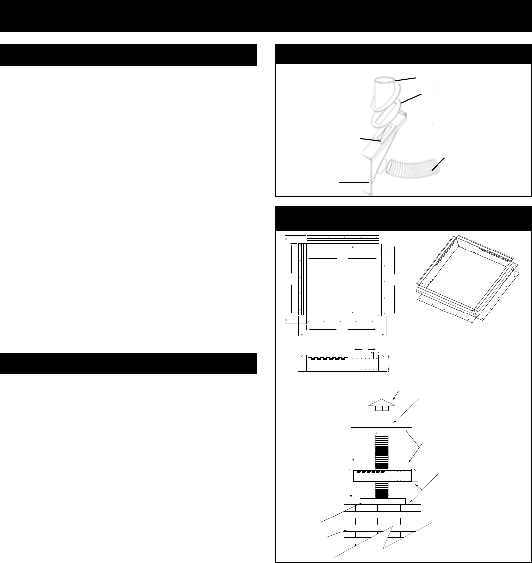
Anadjustablechimneyintakeextension,part#1-00-674104
isavailabletobeusedonmasonrychimneysonly.SeeFig.
48.
Additionalinformationanddiagramscanbefoundonpages
23thru27,underventing.
Toinstalloutsideair,usekitpartnumber1-10-674080.Follow
theinstallationinstructionsprovidedwiththekit.
Outside Air
Chimney cap and flex termination with
flashing plate (by installer) THIS CAP
MUST BE Stainless Steel
With the intake assenbly anchored into
place, finish the 4” SS flex liner and cap
(by installer) by screwing the cap’s flashing
plate to the top of the intake assenbly.
A waterproofing sealant can be used to
seal the corners and irregularities in the top
of the masonry chimney.
After adjusting the intake assembly
for the flue size, secure the
assembly to the top of the chimney
with some form of anchors or
screws.
Masonry Flue Liner
Masonry Chimney
Fig.48
Adjustable Chimney Intake Extension Part # 1-00-674104
18 1/8”
18 1/8”
18”
18”
22 1/8”
18”
22 1/8”
4”
6”
1”
Harman® SS Chimney Top Intake Assembly
23
3-90-00674R28_12/13
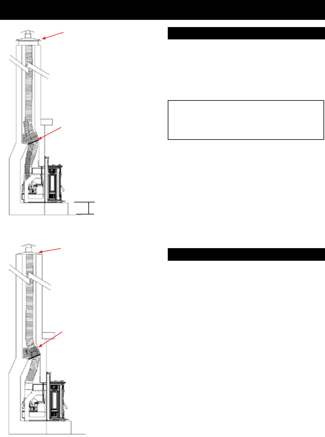
Venting
Thismethodprovidesexcellentventingfornormaloperation.
This method also provides natural draft in the event of a
powerfailure.
Acapshouldbeinstalledonthechimneytokeepoutrain.
Combustionairisprovidedfromthelivingareaandentersthe
feedsystemfromaroundthewingandstovebodyspaces.
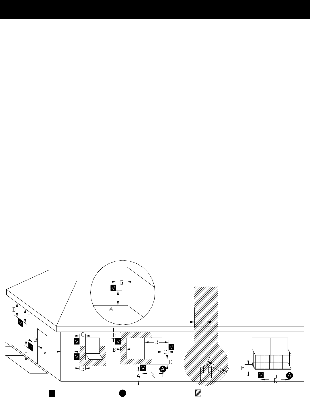
#2 Installing into an existing replace chimney
Thismethodprovidesexcellentventingwith100%outsideair
whichisthemostefcientoperationofthisunit.Thismethod
alsoprovidesnaturaldraftintheeventofapowerfailure.
A4inchstainlesssteelexpipeisneededfortheuepipe,
and 3" aluminum or Stainless Steel Flex Pipe is used for
theintake.
#1 Installing into an existing replace chimney
WARNING
CHIMNEY CONNECTOR PIPE MAY NOT PASS
THROUGH CONCEALED SPACES INCLUDING AN
ATTIC, ROOF SPACE, CLOSET, FLOOR OR CEILING.
Fig.49
Heightofexisting
hearth
Thechimneytopmustbecapped
topreventrainand/orsnowfrom
enteringthechimney.
SeePage22.forinformationon
the optional HarmanAdjustable
StainlessSteelIntakeExtension.
The damper area must be
sealed with a steel plate and it
is recommended that Kaowool,
Mineral wool or an equivalent
non combustible insulation
is used on top of the plate
to reduce the possibility of
condensation. Insulation alone
should not be used to seal the
damperopening.
Fig.50
Thechimneytopmustbecapped
topreventrainand/orsnowfrom
enteringthechimney.
The damper area may be
sealed with a steel plate. If
so, it is recommended that
Kaowool, Mineral wool or an
equivalent non combustible
insulation is used on top of the
platetoreducethepossibilityof
condensation. Insulation alone
should not be used to seal the
damperopening.
24
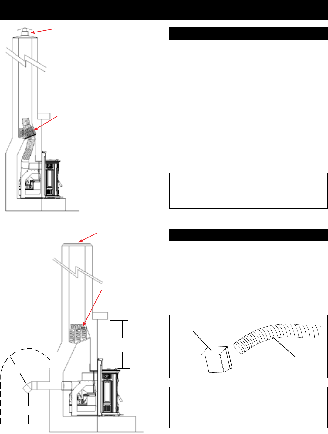
3-90-00674R28_12/13
Thismethodprovidesexcellentventingfornormaloperation.
This method also provides natural draft in the event of a
powerfailure.Ifthechimneyconditionisquestionableyou
maywanttoinstallalinerasinmethod#2.
This is the minimum allowed vent pipe using 4" stainless
steelexpipe.
Theventpipemustextendpastthedampersealingareaby
atleast12inches.
Note:Theinsulationmaterialmustnotbeallowedtoexpand
tothepointthatitcoverstheendoftheexpipe.
Thechimneyshouldbecappedwithanystylecapthatwill
notallowrainorsnowtoenter.
InsomeplacesintheUSandCanada,itisrequiredthatthe
ventpipeextendallthewaytothetopofthechimney.Check
yourlocalcodes.
Fig.51
Venting
#3 Installing into an existing chimney
Thismethodprovidesexcellentventingfornormaloperation
andinareplacewithinadequateuespace,oraheightof
over30feet.A3"or4"PLventpipeshouldbeusedwiththe
neededswiveluestub.
NOTE:Theuestubinsulationwrapmuststillbeusedwith
thismethod.Seepage14,Fig.27&29.Witha100%outside
airkittheoutsideaircanbeinstalledinthesamemanner
astheuepipe.
CAUTION
KEEP COMBUSTIBLES (SUCH AS GRASS, LEAVES,
ETC.) AT LEAST 3 FEET AWAY FROM THE FLUE
OUTLET ON THE OUTSIDE OF THE BUILDING.
Thechimneytopmustbecapped
topreventrainand/orsnowfrom
enteringthechimney.
Stainless Steel Outside Air Inlet Cover
part# 1-10-09542
3" Flex pipe
12"min
Fig.52
36"
Chimneytop
MUST BE SEALED
The damper area must be
sealedwith asteelplateand it
isrecommendedthat Kaowool,
Mineral wool or an equivalent
non combustible insulation
is used on top of the plate
to reduce the possibility of
condensation. Insulation alone
shouldnotbeusedtosealthe
damperopening.
Fiberglassinsulation
packed above the
damperopeningand
sealedplate.(Nota
Harmanproduct.)
#4 Preferred method
WARNING
CHIMNEY CONNECTOR PIPE MAY NOT PASS
THROUGH CONCEALED SPACES INCLUDING AN
ATTIC, ROOF SPACE, CLOSET, FLOOR OR CEILING.
12"min.
25
3-90-00674R28_12/13
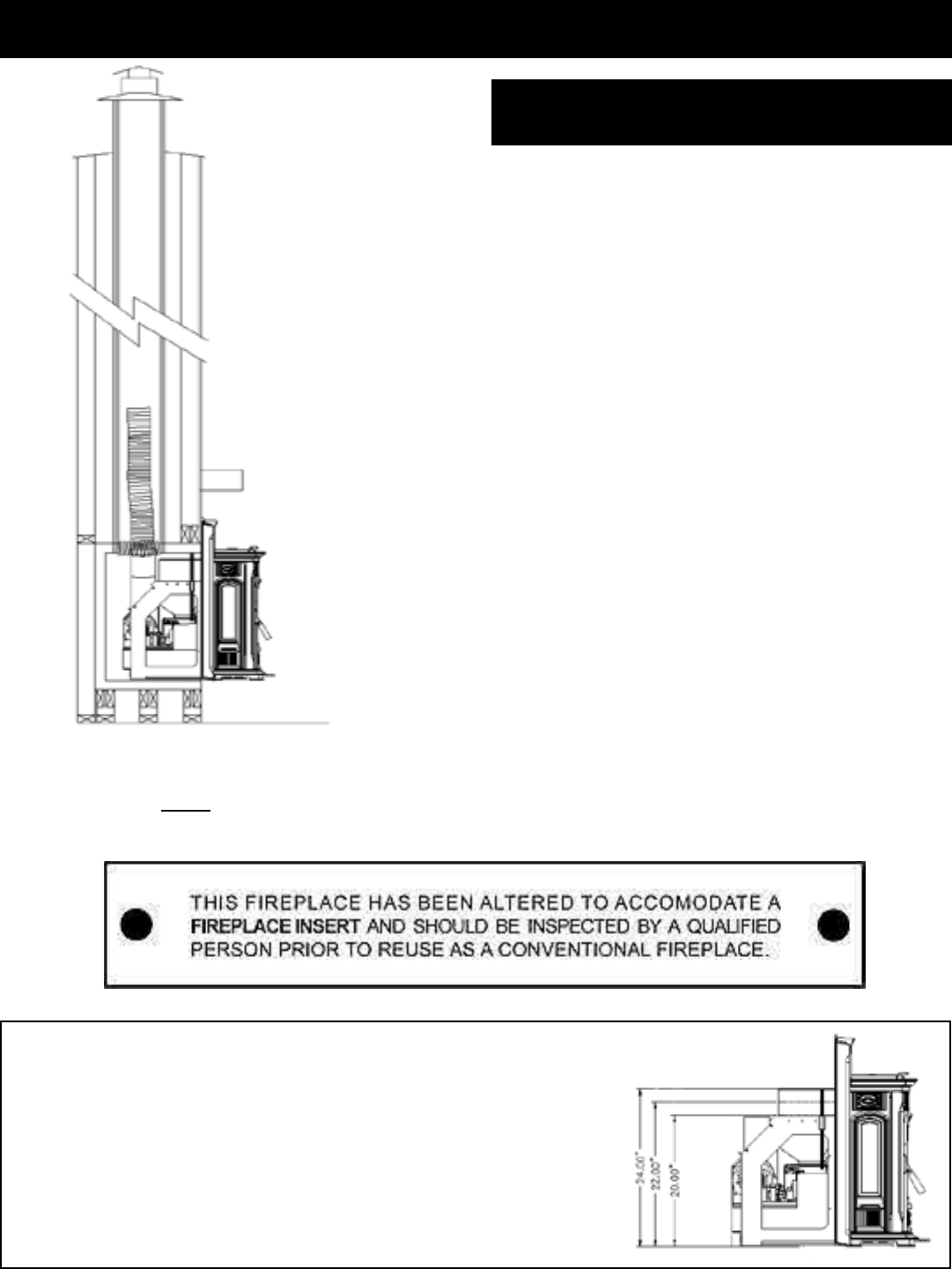
WheninstallingtheAccentraInsertintoafactorybuiltwood
burning replace, the Manufactured Fireplace Installation
Kit#1-00-674205mustbeused.Inaddition,severalthings
needtobetakenintoconsideration.
The size of the replace opening. Will the unit t into the
opening? Many of these units have metal smoke shields
insidethetopthatcanberemovedtogainheight.Oftenthe
sideandrearrefractorycanberemovedtogaindepthand
width.Insomecircumstances,thefrontlowerliporgrillwork
mayalsoberemoved.Besureandfollowtheguidelinesin
thekitinstructions.Becauseofthespecialtracksystem,itis
alsopermittedtoremovetheoorrefractoryand/orinsulation
inthebottomofthemanufacturedreplace,rightdownto
theoutersheetmetal,whichmustbeleftinplaceforoor
protectionundertheinsertmountingframe.Floorprotection
guidelines,aslistedonpage14mustalsobefollowed.
OPTIONAL HOPPER CONFIGURATIONS FOR SMALLER FIREPLACE
OPENINGS:
TheHarmanAccentraInsertcanbefactorybuiltwithshorterhopper
congurations.
Thestandardrequiresa24"opening.Part#1-90-00674
Option1:Requiresa22"openingheight.Part#1-90-00675
Option2:Requiresa20"openingheight.Part#1-90-00676
Keepinmindthehoppercapacitieswilldecreasewiththeoptionalheights.
Venting
Note: If the Harman Accentra Insert is installed into a factory built wood burning replace, this label (Harman
part # 3-90-00675) MUST be attached to the altered replace. This label is included in the Manufactured replace
installation kit.
Fig.54
Installing the Accentra Insert into an existing
factory built wood burning replace
Fig.53
26
3-90-00674R28_12/13
See your dealer for part details and installation
instructions.
Sample Mantel System
Note: Combustible materials areallowedto touchthecabinet anywhere behindthefront mountingangesexcept vent
clearanceareas.Thehearthsubstructuremaybebuiltofcombustiblematerialalthoughanon-combustiblehearthsurface
(tile,stone,metal,glass)mustextendasfarasshownontheappliance'sTestingLabel.
Fig.55
Fig.56
Accentra Insert Zero Clearance Cabinet
Be sure to use approved pellet
vent pipe wall and ceiling pass-
through fittings to go through
combustible walls and ceilings. Be
suretouseastartingcollartoattach
theventing systemtotheue stub
and seal the connection with high
temperaturesilicone.
HarmanZero
Clearancecabinet(top
ueonly)
Part#1-10-674070
Insert Wing & Mounting
Frame
InsertBody
When using 3" or 4" PL vent pipe,
there must be a 3" clearance to
combustibles.
Seenotebelow&refertopage14
foroorprotectionrequirements.
HarmanZeroClearanceBoxFlue
PipeRough-InSupport(optional)
Part#1-00-674119
27
3-90-00674R28_12/13
V=Vent Terminal A=Air Supply Inlet =Area where termination is not permitted
Door
Sidewalk
Fixed
Closed
Openable
Openable Fixed
Closed
Inside Corner
Detail
Porch or
Openable
Deck
or Fixed
H.Aventmustnotbeinstalledwithin3feet(90cm)above
agasmeter/regulatorassemblywhenmeasuredfromthe
horizontalcenter-lineoftheregulator.
I. Theclearancetoserviceregulatorventoutletmustbea
minimumof6feet.
J. Theclearancetoanon-mechanicalairsupplyinlettothe
buildingorthecombustionairinlettoanyotherappliance
mustbeaminimumof48”.
K. Theclearancetoamechanicalairsupplyinletmustbea
minimumof10feet. (with outside air installed, 6 feet )
L. The clearance above a paved sidewalk or a paved
drivewaylocatedonpublicpropertymustbeaminimum
of7feet.
M.Theclearanceunderaveranda,porch,deckorbalcony
mustbeaminimumof12inches. (B. also)
NOTE: The clearance to vegetation and other exterior
combustibles such as mulch is 36” as measured from
the center of the outlet or cap. This 36” radius continues
to grade or a minimum of 7 feet below the outlet.
CertainCanadianandorLocalcodesorregulationsmay
requiredifferentclearances.
A vent shall not terminate directly above a side-walk or
paveddrivewaywhichislocatedbetweentwosinglefamily
dwellingsandservesbothdwellings.
Onlypermitted if veranda,porch,deck, or balconyisfully
openonaminimumof2sidesbeneaththeoor.
NOTE: Where passage through a wall, or partition of
combustible construction is desired, the installation
shall conform to CAN/CSA-B365. (If in Canada)
Venting
Requirements for Terminating the Venting
WARNING: Venting terminals must not be recessed into
a wall or siding.
NOTE: Only PL or L vent pipe wall pass-throughs and re
stops should be used when venting through combustible
materials.
NOTE: Always take into consideration the effect the
prevailing wind direction or other wind currents will
cause with flyash and /or smoke when placing the
termination.
In addition, the following must be observed:
A. Theclearanceabovegrademustbeaminimumof12".
B. Theclearancetoawindowordoorthatmaybeopened
must be a minimum of 48" to the side and 48" below
thewindow/door,and12"abovethewindow/door. (with
outside air installed, 18” to side and below)
C.A 12" clearance to a permanently closed window is
recommendedtopreventcondensationonthewindow.
D.Theverticalclearancetoaventilatedsoftlocatedabove
theterminalwithinahorizontaldistanceof2feet(60cm)
fromthecenter-lineoftheterminalmustbeaminimum
of18".
E. Theclearancetoanunventilatedsoftmustbeaminimum
of12".
F. Theclearancetoanoutsidecorneris11"fromcenterof
pipe.
G.Theclearancetoaninsidecorneris12".
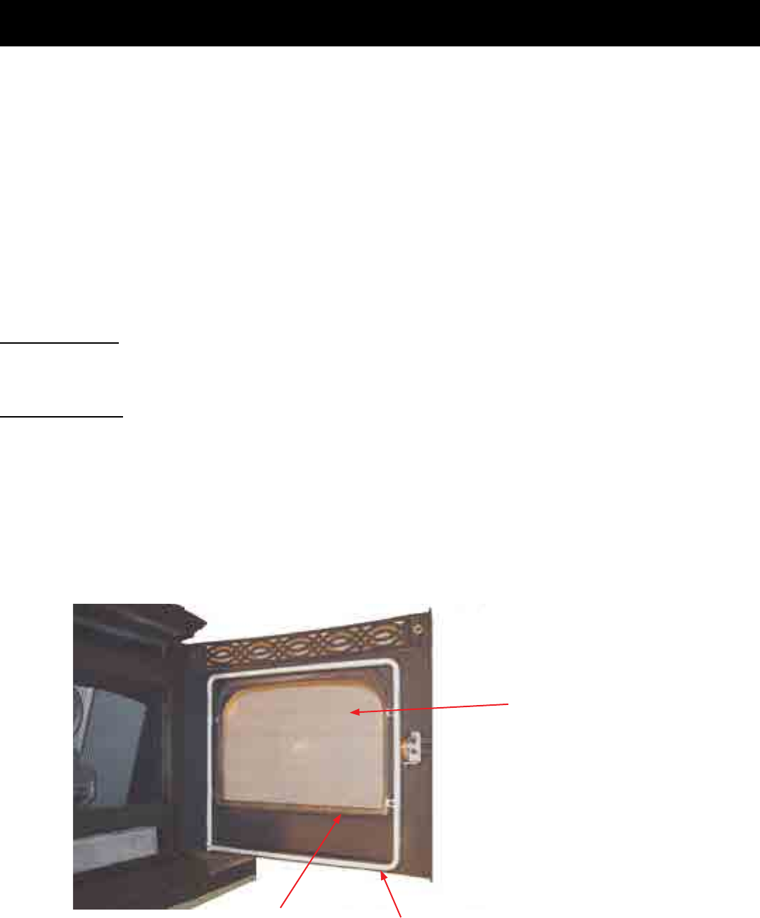
28
3-90-00674R28_12/13
Maintenance - Cleaning Glass on View Door
The glass used in your stove is manufactured to exact standards to withstand the high heat of the re, but like all glass, it
must be treated with common sense and care. Never abuse the glass by slamming the door shut or striking the glass with
a heavy object. If the glass is broken or damaged, do not operate the stove until it has been replaced.
Glass - Replacement
Ifthestove’sglassiscrackedorbroken,youmustreplaceitbeforeoperatingyourstove.Removepiecescarefully.Replace
glassonlywithHarmanreplacementglass;do not use substitutes.
Carefullyremovedamagedglass,gasketmaterial,andholddownclips(setaside).
Installtheselfadhesive1/4"”gasketmaterialaroundthefrontfaceoftheglass.Settheglasspanelandgasketgentlyonto
thedoor.Installtheholddownclipsandtightenwithbolts.
Glass - Cleaning
Sometimesitwillbenecessarytocleanaccumulatedashfromtheglasssurface;allowingthisashtoremainontheglass
forlongperiodscanresultin“etching”duetotheacidityoftheash.Nevercleantheglasswhileitishot,anddo not use
abrasivesubstances.Washthesurfacewithcoolwater,andrinsethoroughly.Youmaywishtouseanon-abrasivecleaner
specicallydesignedforuseonstoveglass.Inanycase,drythoroughlybeforerelightingyourstove.
Disposal of ashes:Ashesshouldbeplacedinametalcontainerwithatightttinglid.Theclosedcontainerofashesshould
beplacedonanon-combustibleoororontheground,wellawayfromallcombustiblematerials,pendingnaldisposal.If
theashesaredisposedofbyburialinsoilorotherwiselocallydispersed,theyshouldberetainedintheclosedcontainer
untilallcindershavethoroughlycooled.
Soot and y ash: Formationandneedforremoval.The productsof combustion contain small particlesof y ash.The
yashwillcollectintheexhaustventingsystemandwillrestricttheowoftheuegases.Pelletfuelshavedifferentash
contentsdepending on what type of wood has been used to make the pellets. We recommend to clean the system
after approximately 1 ton of pellets have been burned and judge from that how often the stove should be cleaned,
remember if you change pellets it may change how often you have to clean your stove.
Whenburningwoodslowly,thepotentialexistsforcreosotetoform.Theventingsystemshouldbeinspectedperiodically
throughouttheheatingseasontodetermineifacreosotebuilduphasoccurred.Ifasignicantlayerofcreosotehasaccumulated
(3mmormore),itshouldberemovedtoreducetheriskofachimneyre.Ifareoccurs,calltheredepartment,shutdown
the stove, and evacuate the residence. Before using the appliance, have the venting system thoroughly inspected and
replaceanydamagedcomponents.
Glass Gasket
Replace glass only with high
temperature ceramic glass.
Inspect door gasket during
cleaning and inspection
Fig.57
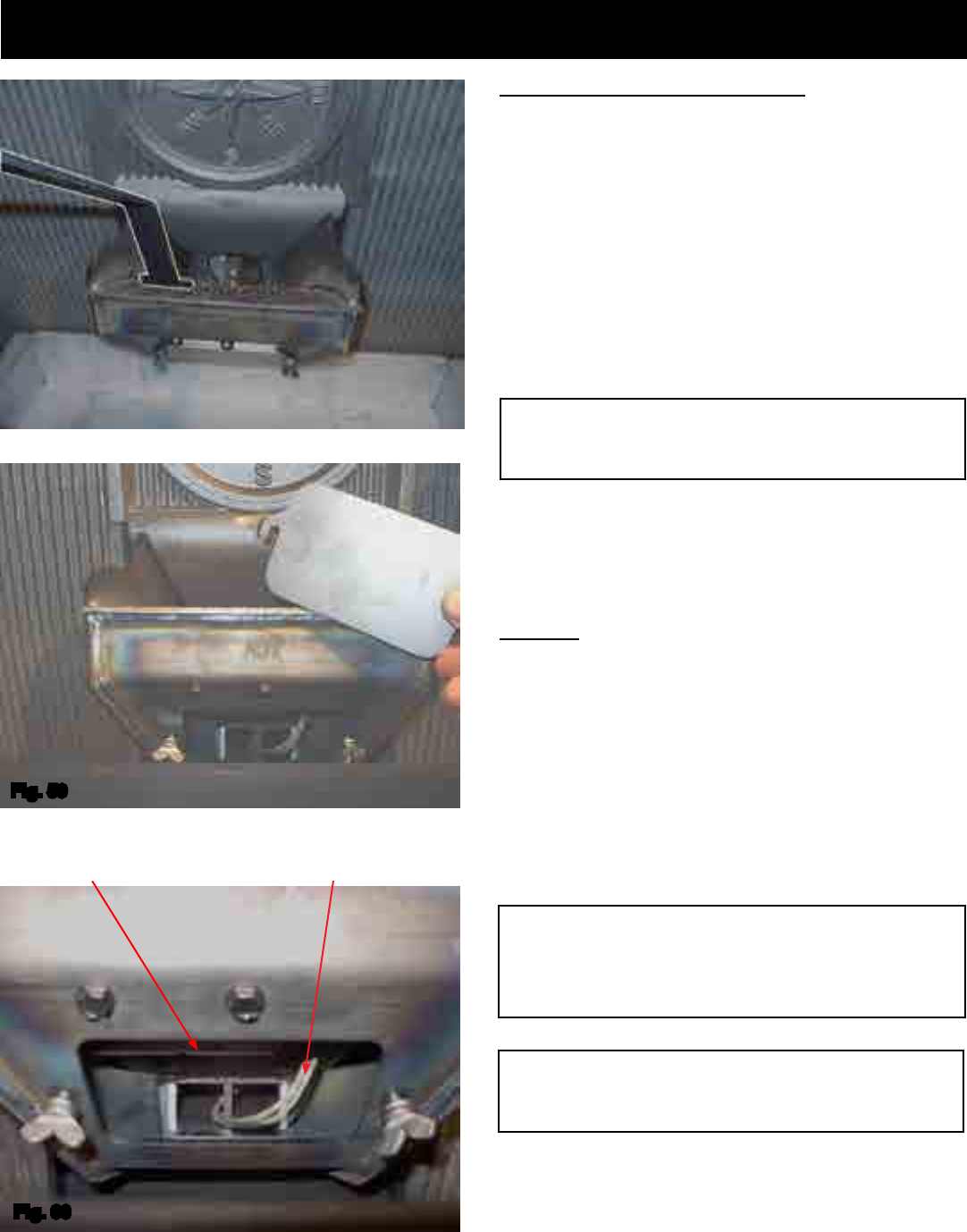
29
3-90-00674R28_12/13
Burn Pot Cleaning and Maintenance
Wheneveraddingfuel,taketheopportunitytocleantheburn
pot.(Weekly at minimum)
• Scrape the top holed surface and sides of the burn
potdowntoauger tube.(Fig 58)Itisnotnecessaryto
completely remove all material from the burn pot. The
excesswillbepushedoutduringthenextuse.
Monthly, or after each ton of fuel burned:
• Loosenthe(2)wingthumbscrewsonthelowerfrontangle
oftheburnpot.(Fig.59)
• Liftofftheclean-outcover(Fig.59)toopenthebottom
clean-outchamber.(Fig.60)
• Cleanashbuildupfrominsidethechamberwhilecover
isoff.Usethescrapertotaponthetopfrontedgeofthe
burn pot. This will help knock pieces of ash, loosened
bythescrapingprocess,downthroughtheholes.Italso
helpsknockscaleoffoftheigniterelement.
Figure 60
Theigniterismadetoberemovableforservicebyinsulated
male/femalewireconnectors.Theseconnectionsbetween
thehot leads (thewiresinside the burnpot)and thecold
leads(thewiresfromthecontrolboard)arealwayspulled
totheinsiderearofthefeederbody. (Not coiled inside the
burn pot.)
Itisveryimportantthattheseconnectionsaretotheinside
rearofthefeederbody.Also,theextrawireoftheigniterwire
serviceloopmustbepulledoutthroughtherearofthefeeder
andtiedupsothatitwillnotbedamagedbyanymovingparts.
DANGER
Disconnect the power to the unit before removing
cover.
Note: The hot lead/cold lead connection must always be
pulled to the rear of the feeder body before operation.
Maintenance - Burn Pot
Fig.58
Fig. 59
Viewed from below through the ash pan opening.
WARNING
Use caution when cleaning burn pot clean-out
chamber. Do not damage the high temperature igniter
wires.
Igniter hot lead wires
(High temperature)
Fig. 60
Burn pot igniter
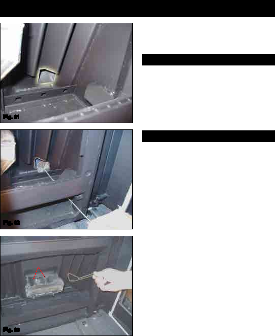
30
3-90-00674R28_12/13
Maintenance - Cleaning
Monthly Cleaning- continued:
Thereisa2"squareexhausttubeoneachside(lowerleft
andrightcorners)oftherebox.Theycanonlybeseenwith
thecastheatexchangercoversremoved.
Usingthecleaningbrushprovided,cleanthesetubesafter
every1tonofpelletsareused.
Thesetubesare an importantpartoftheheatexchanger.
Efciencywillbelostiftheyarenotproperlymaintained.The
rightsidetubeisastraightpassagetothecombustionblower
chamber.TheLeftsidetubefollowsstraightbackthenmakes
arightturn,acrosstheback, to the combustionchamber.
Youwillneedtousetheentirelengthofthecleaningbrush
handletoproperlycleanthistube.
Cleaning the Heat Exchanger tubes
The accordion heat exchanger surfaces are the primary
sourceofheattransferintotheroom.Therefore,itisvery
importanttokeepthemcleanfromyashandsootbuildup.
• The heat exchanger surfaces should be cleaned after
approximatelyevery1tonofpelletsareused.
• Use the scraper provided to clean all the way into the
point.
• Note:An old paint brush works well to clean these
surfaces.
• Note:Theunit“mustbecold”beforeusinganythingother
thanawirebrush.
• Thereare2primaryairinletholesontherearangeof
theburnpot.Theyshouldbecheckedforblockageand
cleanedwithavacuumifnecessary.Note:Thebottomof
theameguidehas2notchesthatmatchtheholes.
Cleaning the Heat Exchanger
PrimaryAirInlets
Fig. 63
Fig. 61
Fig. 62
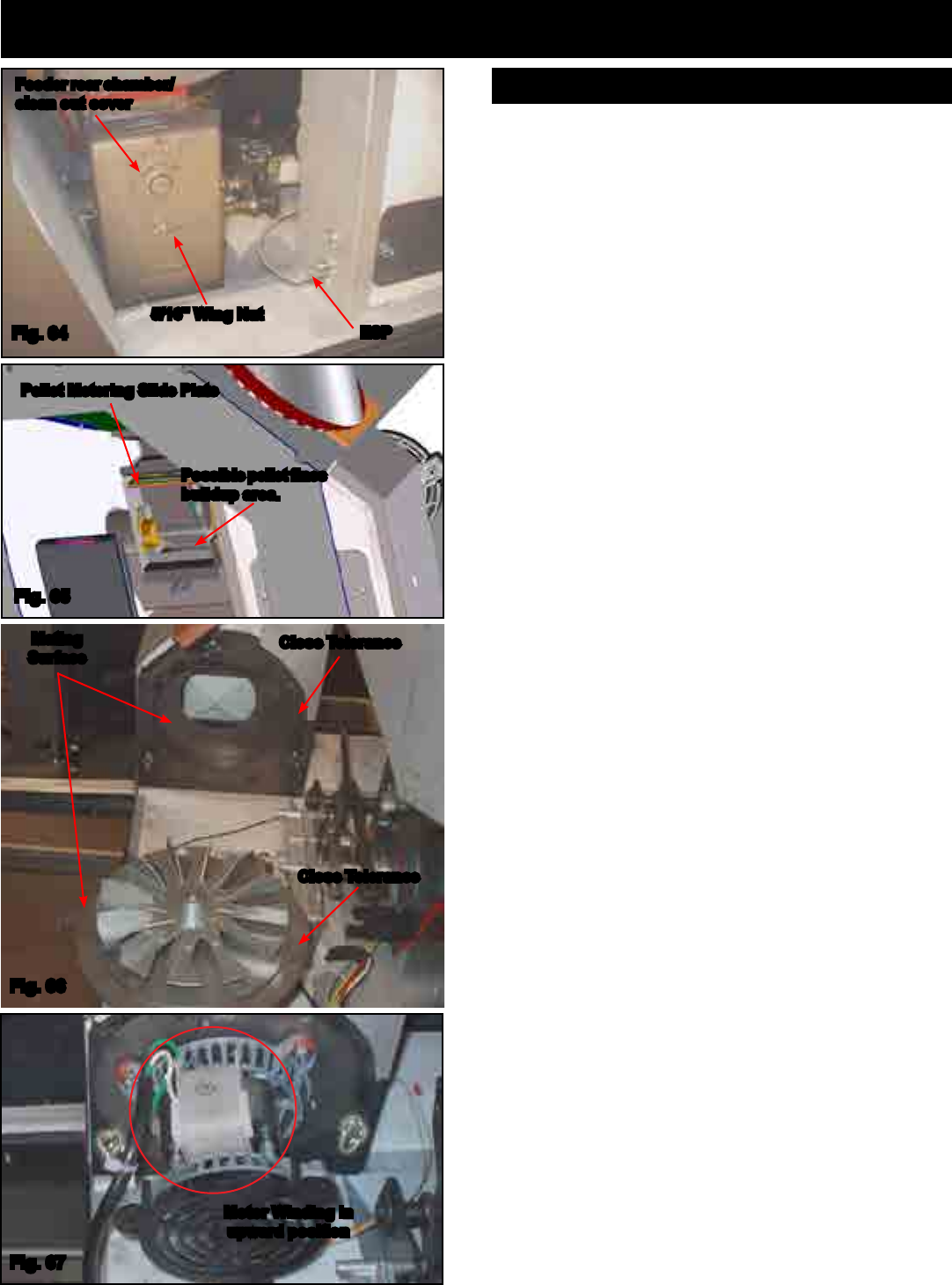
31
3-90-00674R28_12/13
Maintenance - Cleaning
This chamber may get a buildup of nes from the feeder
mechanismmovement.Thisarea shouldbechecked and
cleanedatleastonceayear.
To remove the feeder cover:
• Removethe5/16"wingnut.
• Slidethecoveroffofthethreadedstud.
• Inspectandcleantheinnerchamberifnecessary.See
Fig.65.
• Reinstallthecovermakingcertainitiscenteredonthe
feederbodyandtightenastightlyasyoucanbyhand.
Thecombustionblowerismadetoberemovedeasilyfor
inspectionandcleaning.SeeFig.67.
The combustion blower is mounted on a precision cut
gasketlessmountingplate.Thisplateisheldintoplace
with(3)thumbscrews.SeeFig.67.
To remove the combustion blower:
• Turnthethumbscrewscounterclockwiseapproximately5
turns.Rotatetheentireassemblycounterclockwiseuntil
thepointsoftheretainingslotsarevisible.
• Removetheblowerassemblywiththefanbladebypulling
itdirectlyawayfromtheblowerhousing.
• Thecordonthemotorislongenoughtoallowthemotor
tobesetdownontheblackplasticfancover.Thisallows
foreasyaccesstoinspectandcleanthearea.SeeFig.
66.
• Withtheblowerassemblyout,inspectionshouldbedone
onthesurfacesoftheblowerassemblyandthehousing
opening where they meet. These surfaces MUST be
cleanandfreefromdirt,grit,yash,sootornicksinthe
metal.Thisgasketlesssealreliesonanextremelyclose
tolerance. Therefore, anything other than a clean joint
maycauseexhaustgasesand/oryashtoescape.
• Theassemblycanonlybereinstalledinoneposition:with
themotorwindingintheupwardlocation.SeeFig.67.The
mountingplatewillnotallowforanyotherposition.
• Alwaysmakesurethattheassemblyisfullyseatedand
the(3)thumbscrewsaretightenedbeforeoperatingthe
unit.
Feeder Chamber
Pellet Metering Slide Plate
Possible pellet nes
buildup area.
Fig. 65
5/16" Wing Nut
ESP
Feeder rear chamber/
clean out cover
Fig. 64
Mating
Surface
Close Tolerance
Fig. 66
Close Tolerance
Fig. 67
Motor Winding in
upward position
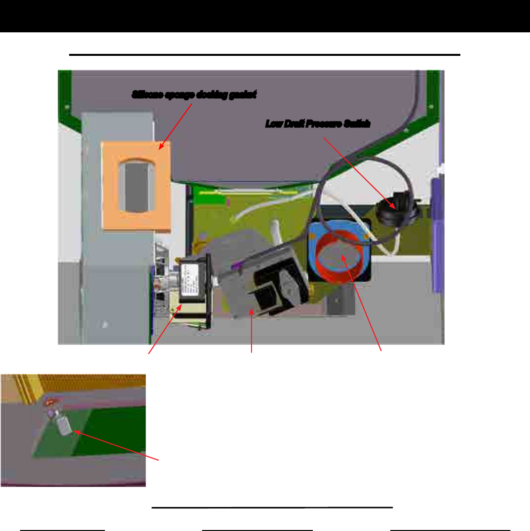
32
3-90-00674R28_12/13
The Low Draft Pressure Switch is a
differentialpressureswitchthatmonitors
the negative pressure (Draft) in the
rebox.If the draftbecomestoo low for
proper combustion, the switch opens,
cuttingpowertothefeedmotorandthe
ignitercircuits.Thisswitch is connected
intotheAC(highvoltage)wiring.
The Control Board/ESP combination
is responsible for all high limit safety
control.Thereare2highlimits,onenormal
operation high limit and one backup
highlimit.Thecontrolhas an automatic
diagnostic circuit that continuously
monitorstheESPandRoomSensorfor
faults.Ifafaultshouldoccur,thecontrol
sends a status alert and at the same
timetheunitgoesdowntominimumfeed/
minimumburnasasafetycondition.
Accentra Insert Motor & Component Locations
Accentra Pellet Insert Safety Devices
Distribution Blower (under unit) See Fig. 10, Page 9.
Motor & Component Locations
The Hopper Lid Position Switchisfound
intherearcornerofthehopperopening.
If the hopper lid is not fully closed, the
switch opens, interrupting the power to
thefeedmotorandtheignitercircuits.This
preventspossibleinjuryfromreachinginto
thefeedermechanismduringoperation.
Hopper Lid Position Switch
Backdraft Damper Assembly
Always check to see if the damper plate
swings freely inward and that the seating
edgesarenotcoveredwithdirtorlint.
Low Draft Pressure Switch
Feed MotorCombustion Motor
Silicone sponge docking gasket

33
3-90-00674R28_12/13
Trouble-Shooting
Cleaning Burn Pot
Wheneveryourstoveisnotburning,taketheopportunityto
scrapethe burnpot toremove carbon buildup.A vacuum
cleanerishandytoremovetheresidue.Besurethestove
iscoldifyouuseavacuum.
Carbonbuildupcanbescrapedloosewiththereburning
usingthespecialtoolprovidedwithyourstove.Scrapethe
oorandsidesoftheburnpot.Thecarbonwillbepushedout
bytheincomingfuel.Alwayswearglovestodothis.
Removing Ashes
TurntheTempDialtonumber1approximately30minutes
beforeremovingashes.Thiswillresultinacoolerstoveand
ashpan.
Maximum FeedAdjuster settings are not needed in most
cases.Operatinginthenormalrange(#4)isrecommended
whenmaximumheatoutputisnotrequired.TheESPprobe
preventsthestovefrombeingover-red.
Keepthestovefreeofdustanddirt.
Helpful Hints
Fuel
STOVE DOES NOT FEED
1. Nofuelinhopper.
2. Fireboxdraftmaybetoolowforsensingswitchinfeeder
circuit to operate. Check for closed doors, loose or
missinggasketondoorsorhopperlid.
3. Hopperlidmustcontactthelidpositionswitch.
4. FeedmotorwillnotrununtiltheESPcontrolsensesa
certaintemperature.Maybeyoudidnotputenoughfuel
orstartinggelintheburnpotbeforemanuallylightingthe
re.
5. Restrictioninthehopperorfeeder.Removeallfueland
examine.Cleartheobstruction.
6. Feedmotorhasfailed.
PARTIALLY BURNED PELLETS
1. Feedratetoohigh.
2. Poorairtofuelmixture.(Checkburnpotclean-outcover
andairintake).
3. Burn pot or heat exchanger tubes may need to be
cleaned.
4. Combinationofalltheabove.
5. #6 status blink:A6blinkcontrolboardstatusindication
iscausedbypoororincompletecombustion.Thecircuit
boardhastheabilitytotrackthecombustionthroughfeed
settingsandESPtemperatures.Whenthecontrolboard
hascalculatedpoororincompletecombustion,itwillshut
downthe unitas a safetyfeature. (Poor orincomplete
combustionisacontributorofcreosotewhichmaycause
achimneyre)
A6blinkstatusmaybecausedbyseveralthings:
1. Blockedorpartiallyblockedue.
2. Blockedorpartiallyblockedinletair.
a. Backdraft damper on the inlet pipe may be stuck
closed.
b. If outside air is installed, the inlet cover may be
blocked.
3. Theairchamberundertheburnpotmaybelledwithnes
andsmallbitsofash.
4. Theholesintheburnpotmaybegettinglledwithashor
carbonbuildup.
5. Combustionblowerfanbladesmayneedcleaned.
6. Fuelrestrictionsasnotedabove.
SMOKE SMELL
Sealtheventpipejointsandconnectiontostovewithsilicone.
Theexhaustventistheonlypartofthesystemthatisunder
positivepressure.
FIRE HAS GONE OUT- Check for status light.
1. Nofuelinhopper.
2. Draftistoolow,blockedue.
3..Somethingisrestrictingfuelow.
4. Hopperlidnotclosedproperly.
5.Feedmotororcombustionblowerhasfailed.
SMOKE IS VISIBLE COMING OUT OF VENT
1. Air-fuelratioistoorich.
a.Feedratetoohigh.
b.Drafttoolowcausedbyagasketleak.
LOW HEAT OUTPUT
1. Feedratetoolow
2. Drafttoolowbecauseofgasketleak.
3. Poorqualityordamppellets
4. Combinationof1and2.
TheAccentraisapprovedforburninganygradeofpelletized
bio-massfuel.Itisalsoapprovedforburningshelledcornin
amixturewithwoodpellets,upto50%.(SeePage46)
It should be noted, however, that higher ash content will
requiremorefrequentashremoval,scrapingoftheburnpot,
andmayprovidelessBTU'sperpound.
Themoisturecontent of pelletsmustnotexceed8%,and
cornmustnotexceed15%.HighermoisturewillrobBTU's
andmaynotburnproperly.
Fuel should not be stored within the stove installation
clearancesorwithinthespacerequiredforchargingandash
removal.SeePage14.
34
3-90-00674R28_12/13
Specications
Weight 450 lbs.
Blower 180 cfm
Hopper Capacity 57 lbs. (24" hopper #1-90-00674)
Fuel Wood Pellets
Outside Air Size 3 inches
Fuse Rating 6 amp
BTU Range 0 to 42,000
Feed Rate .75 lbs./hr. on minimum(on maintenance)
5 lbs./ hr. on maximum
Vent Size 4 inch Pellet Vent Pipe, standard,
3 inch Pellet Vent Pipe, option
Maximum Wattage 440 Watts (Start cycle and test)
Start Cycle Wattage 340 Watts
Normal Run Wattage 255 Watts
31 5/16
41 3/4
32 1/8
24"
22"
20"
19 3/8
16 1/4 14 3/8
12 5/8
25 7/8
Unit #1-90-00674 - Hopper Capacity 57 lbs. - 25.85 kg
Unit #1-90-00675 - Hopper Capacity 48 lbs. - 21.75 kg
Unit #1-90-00676 - Hopper Capacity 38 lbs. - 17.25 kg
1 1/2
19 1/2
24 1/2
26 7/8
14 3/8
16 7/16
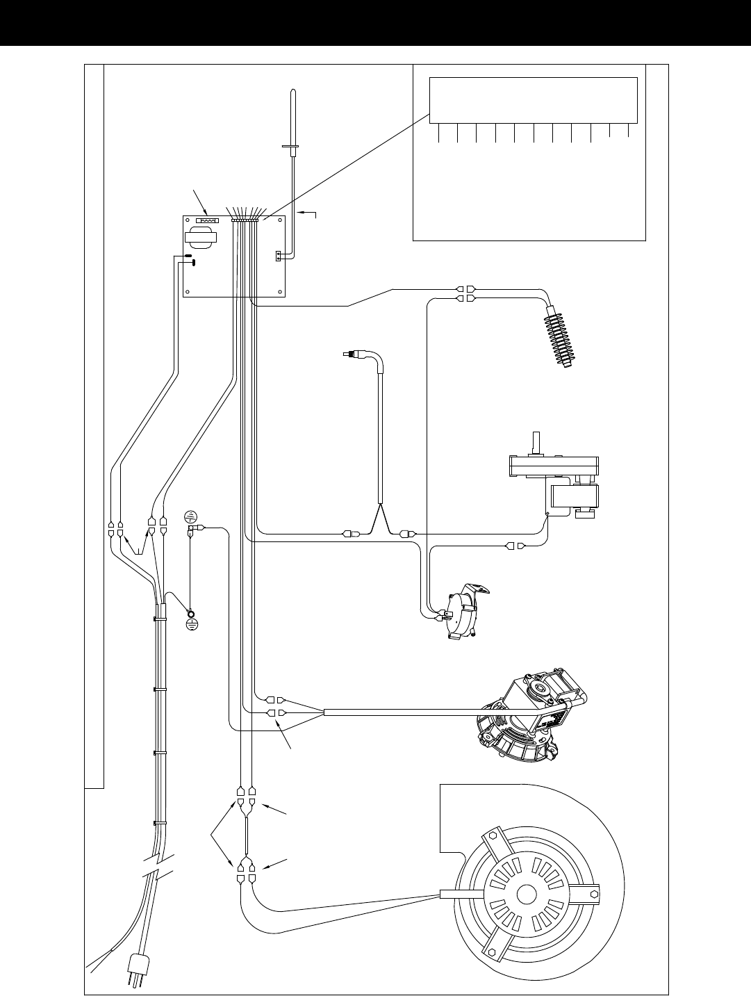
35
3-90-00674R28_12/13
Accentra Insert Wiring Diagram
-- 5.4 A. --MAX. WATTS 640
DISTRIBUTION BLOWER
PLUGGED
PART NO. 3-90-09321
120 VOLTS A.C. 60 HZ.
BLACK
BLUE
YELLOW
RED
WHITE
WHITE
EMPTY
WHITE
WHITE
BROWN
WHITE 11 PIN PLUG
11
8
10
9
6
5
7
2
4
3
1
ROOM SENSOR Wire
for external location
BLACK
WHITE
18/3 10 Amp POWER CORD
MALE/FEMALE CONNECTIONS
WHITE
BLUE
WHITE
BONDED TO STOVE WING
GREEN WIRE IS GROUND
RED
GREEN
6 AMP GLASS FUSE
HARMAN - ACCENTRA INSERT PELLET STOVE # 1-90-00674
BROWN
GREEN/YELLOW
WHITE
GREEN WIRE IS GROUND
BONDED TO STOVE BODY
BLACK
WHITE
MALE/FEMALE CONNECTIONS
BLACK
WHITE
TWISTED WIRE
BOARD
CONTROL
YELLOW
ESP
4
5
6
8
11
9
10
1
3
ROOM SENSOR Wires
twisted pair wire
ESP PROBE
SKY BLUE
SKY BLUE
IGNITER ELEMENT
FEEDER MOTOR
COMBUSTION MOTOR
LOW PRESSURE SWITCH
BLACK
BLACK
CONNECTION NOT COLOR SPECIFIC
HARNESS THROUGH BODY
N.O. CONTACTS
HOPPER LID SWITCH
3-20-232108
N.O. CONTACTS
3-90-00674R28_12/13
4021-645F02-18-13
Page1of2
Hearth & Home Technologies
LIMITED LIFETIME WARRANTY
Hearth&HomeTechnologies,onbehalfofitshearthbrands(”HHT”),extendsthefollowingwarrantyforHHT
gas,wood,pellet,coalandelectrichearthappliancesthatarepurchasedfromanHHTauthorizeddealer.
WARRANTY COVERAGE:
HHTwarrantstotheoriginalowneroftheHHTapplianceatthesiteofinstallation,andtoanytransfereetakingownership
oftheapplianceatthesiteofinstallationwithintwoyearsfollowingthedateoforiginalpurchase,thattheHHTappliance
willbefreefromdefectsinmaterialsandworkmanshipatthetimeofmanufacture.Afterinstallation,ifcoveredcompo-
nentsmanufacturedbyHHTarefoundtobedefectiveinmaterialsorworkmanshipduringtheapplicablewarrantyperiod,
HHTwill,atitsoption,repairorreplacethecoveredcomponents.HHT,atitsowndiscretion,mayfullydischargeallofits
obligationsundersuchwarrantiesbyreplacingtheproductitselforrefundingtheverifiedpurchasepriceoftheproduct
itself.Themaximumamountrecoverableunderthiswarrantyislimitedtothepurchasepriceoftheproduct.Thiswarranty
issubjecttoconditions,exclusionsandlimitationsasdescribedbelow.
WARRANTY PERIOD:
Warrantycoveragebeginsonthedateoforiginalpurchase.Inthecaseofnewhomeconstruction,warrantycoverage
beginsonthedateoffirstoccupancyofthedwellingorsixmonthsafterthesaleoftheproductbyanindependent,
authorizedHHTdealer/distributor,whicheveroccursearlier.Thewarrantyshallcommencenolaterthan24months
followingthedateofproductshipmentfromHHT,regardlessoftheinstallationoroccupancydate.Thewarrantyperiodfor
partsandlaborforcoveredcomponentsisproducedinthefollowingtable.
Theterm“LimitedLifetime”inthetablebelowisdefinedas:20yearsfromthebeginningdateofwarrantycoveragefor
gasappliances,and10yearsfromthebeginningdateofwarrantycoverageforwood,pellet,andcoalappliances.These
timeperiodsreflecttheminimumexpectedusefullivesofthedesignatedcomponentsundernormaloperatingconditions.
Seeconditions,exclusions,andlimitationsonnextpage.
Parts Labor Gas Wood Pellet EPA
Wood
Coal Electric Venting
XXXXXXX
Allpartsandmaterialexceptas
coveredbyConditions,
Exclusions,andLimitations
listed
XXX Igniters,electroniccomponents,
andglass
X X X X X Factory-installedblowers
X Moldedrefractorypanels
X Firepotsandburnpots
5years 1year X X Castingsandbaffles
7years 3years X X X Manifoldtubes,
HHTchimneyandtermination
10
years
1year X Burners,logsandrefractory
Limited
Lifetime
3years X X X X X Fireboxandheatexchanger
XXXXXXX Allreplacementparts
beyondwarrantyperiod
WarrantyPeriod HHTManufacturedAppliancesandVenting
1Year
ComponentsCovered
3years
2years
90Days

3-90-00674R28_12/13
4021-645F02-18-13 Page2of2
WARRANTY CONDITIONS:
• ThiswarrantyonlycoversHHTappliancesthatarepurchasedthroughanHHTauthorizeddealerordistributor.Alistof
HHTauthorizeddealersisavailableontheHHTbrandedwebsites.
• ThiswarrantyisonlyvalidwhiletheHHTapplianceremainsatthesiteoforiginalinstallation.
•ThiswarrantyisonlyvalidinthecountryinwhichtheHHTauthorizeddealerordistributorthatsoldtheappliance
resides.
• Contactyourinstallingdealerforwarrantyservice.Iftheinstallingdealerisunabletoprovidenecessaryparts,contact
thenearestHHTauthorizeddealerorsupplier.Additionalservicefeesmayapplyifyouareseekingwarrantyservice
fromadealerotherthanthedealerfromwhomyouoriginallypurchasedtheproduct.
• Checkwithyourdealerinadvanceforanycoststoyouwhenarrangingawarrantycall.Travelandshippingcharges
forpartsarenotcoveredbythiswarranty.
This warranty is void if:
• Theappliancehasbeenover-firedoroperatedinatmospherescontaminatedbychlorine,fluorine,orotherdamaging
chemicals.Over-firingcanbeidentifiedby,butnotlimitedto,warpedplatesortubes,rustcoloredcastiron,bubbling,
crackinganddiscolorationofsteelorenamelfinishes.
• Theapplianceissubjectedtoprolongedperiodsofdampnessorcondensation.
• Thereisanydamagetotheapplianceorothercomponentsduetowaterorweatherdamagewhichistheresultof,but
notlimitedto,improperchimneyorventinginstallation.
LIMITATIONS OF LIABILITY:
• Theowner’sexclusiveremedyandHHT’ssoleobligationunderthiswarranty,underanyotherwarranty,expressor
implied,orincontract,tortorotherwise,shallbelimitedtoreplacement,repair,orrefund,asspecifiedabove.Inno
eventwillHHTbeliableforanyincidentalorconsequentialdamagescausedbydefectsintheappliance.Somestates
donotallowexclusionsorlimitationofincidentalorconsequentialdamages,sotheselimitationsmaynotapplytoyou.
Thiswarrantygivesyouspecificrights;youmayalsohaveotherrights,whichvaryfromstatetostate.EXCEPTTO
THEEXTENTPROVIDEDBYLAW,HHTMAKESNOEXPRESSWARRANTIESOTHERTHANTHEWARRANTY
SPECIFIEDHEREIN.THEDURATIONOFANYIMPLIEDWARRANTYISLIMITEDTODURATIONOFTHE
EXPRESSEDWARRANTYSPECIFIEDABOVE.
WARRANTY EXCLUSIONS:
Thiswarrantydoesnotcoverthefollowing:
• Changesinsurfacefinishesasaresultofnormaluse.Asaheatingappliance,somechangesincolorofinteriorand
exteriorsurfacefinishesmayoccur.Thisisnotaflawandisnotcoveredunderwarranty.
• Damagetoprinted,plated,orenameledsurfacescausedbyfingerprints,accidents,misuse,scratches,melteditems,
orotherexternalsourcesandresiduesleftontheplatedsurfacesfromtheuseofabrasivecleanersorpolishes.
• Repairorreplacementofpartsthataresubjecttonormalwearandtearduringthewarrantyperiod.Theseparts
include:paint,wood,pelletandcoalgaskets,firebricks,grates,flameguides,batteriesandthediscolorationofglass.
• Minorexpansion,contraction,ormovementofcertainpartscausingnoise.Theseconditionsarenormalandcom-
plaintsrelatedtothisnoisearenotcoveredbythiswarranty.
• Damagesresultingfrom:(1)failuretoinstall,operate,ormaintaintheapplianceinaccordancewiththeinstallation
instructions,operatinginstructions,andlistingagentidentificationlabelfurnishedwiththeappliance;(2)failureto
installtheapplianceinaccordancewithlocalbuildingcodes;(3)shippingorimproperhandling;(4)improperopera-
tion,abuse,misuse,continuedoperationwithdamaged,corrodedorfailedcomponents,accident,orimproperly/
incorrectlyperformedrepairs;(5)environmentalconditions,inadequateventilation,negativepressure,ordrafting
causedbytightlysealedconstructions,insufficientmake-upairsupply,orhandlingdevicessuchasexhaustfansor
forcedairfurnacesorothersuchcauses;(6)useoffuelsotherthanthosespecifiedintheoperatinginstructions;(7)
installationoruseofcomponentsnotsuppliedwiththeapplianceoranyothercomponentsnotexpresslyauthorized
andapprovedbyHHT;(8)modificationoftheappliancenotexpresslyauthorizedandapprovedbyHHTinwriting;
and/or(9)interruptionsorfluctuationsofelectricalpowersupplytotheappliance.
• Non-HHTventingcomponents,hearthcomponentsorotheraccessoriesusedinconjunctionwiththeappliance.
• Anypartofapre-existingfireplacesysteminwhichaninsertoradecorativegasapplianceisinstalled.
• HHT’sobligationunderthiswarrantydoesnotextendtotheappliance’scapabilitytoheatthedesiredspace.Informa-
tionisprovidedtoassisttheconsumerandthedealerinselectingtheproperappliancefortheapplication.Consider-
ationmustbegiventoappliancelocationandconfiguration,environmentalconditions,insulationandairtightnessof
thestructure.
3-90-00674R28_12/13
3-90-00674R28_12/13
3-90-00674R28_12/13
3-90-00674R28_12/13
3-90-00674R28_12/13
3-90-00674R28_12/13

44
3-90-00674R28_12/13
Addendum
Minimizing Smoke During Loss of Power Using Battery Back-up
Harman® strongly recommends installing battery back-up to minimize entry of smoke into the
room in the event of power loss.
Your pellet/biomass burning appliance relies on a combustion blower to remove exhaust. A power failure
will cause the combustion blower to stop. This may lead to exhaust seeping into the room. Vertical rise
in the venting may provide natural draft. It is, however, no guarantee against leakage.
There are two Harman® approved battery back-up options for your appliance:
Uninterruptible Power Supply (UPS) UPS battery back-ups are available online or at computer and
ofce equipment stores. Your Harman® appliance with Rev E or later software available beginning in
November 2010 may be plugged directly into a Harman® approved UPS:
• The APC (American Power Conversion) model #BE750G and the TrippLite model
INTERNET750U are tested and approved. Other brands or models may not be compatible.
When power is lost, a fully charged UPS will power a safe, combustion blower only shut-down. Your
appliance will pulse the blower every few seconds to clear exhaust until the re is out. NOTE: The UPS
provides safe shut-down only. It is not intended for continued operation.
Your appliance will recognize when power is restored. What happens depends on ESP temperature
and whether it is equipped with automatic ignition:
• In “Automatic” setting, units equipped with automatic ignition will respond to the set point
and ESP temperature and resume normal operation.
• In “Manual” setting or for units without automatic ignition:
• If the ESP is cool, the appliance will remain shut down.
• If the re is out and the ESP is still warm, the feeder may restart. Since the re is out, the
ESP temperature will not rise. The unit will then shut-down, and may ash a six-blink status
error. (See ESP error codes)
• If the re is still burning, it will resume normal operation.
Contact your dealer if you have questions about UPS compatibility with your appliance.
Harman® Surere 512H Battery Back-up
The 512H connects to a 12 volt deep cycle battery that will
run your appliance for up to eight (8) hours. It includes a trickle charge feature that keeps your battery
charged when power is available. NOTE: If the power is out for longer than battery life, smoke
leakage may still occur unless your stove has been safely shut down.
CAUTION! Always keep appliance doors and hopper lid closed and latched during operation
and during power failures to minimize risk of smoke or burn-back.
CAUTION! Use only Harman® approved battery back-up devices. Other products may not
operate properly, can create unsafe conditions or damage your appliance.
Power Failures / Back-up Power

3-90-00674R28_12/13
45
Fuel and Fuel Storage
Pellet fuel quality can uctuate from manufacturer to
manufacturer,andevenfrombagtobag.
Hearth&HomeTechnologiesrecommendsusingonlyfuel
thatiscertiedbythePelletFuelsInstitute(PFI).
FuelMaterial
• Madefromsawdustand/orotherwoodby-products
• Shelledeldcorn(whenmixedwithwoodpellets)
• Sourcematerialtypicallydeterminesashcontent
HigherAshContentMaterial
• Hardwoodswithhighmineralcontent
• Barkandleavesassourcematerial
• “Standard”gradepellets,cornandotherbiomass
LowerAshContentMaterial
• Softwood;pine,r,etc.
• Materialswithlowermineralcontent
• “Premium”gradepellets
Shelledeldcorn
• Mustbe15%moisturecontentorless
• Mustbecleanandfreeofdebris
• Mustbemixedwithwoodpellets.(Upto50%)
• Stalk parts, excessive nes and cob remnants may
causefeedsystemjamsorblockage
CAUTION! Do not burn fuel that contains an additive;
(such as soybean oil)
• Maycausehopperre
• Damagetoproductmayresult
Read the list of ingredients on the packaging. If you are
buyingeldcorn,theonlyingredientlistedshouldbeeld
corn.
WARNING! Risk of Chemical Poisoning!
DoNOTburntreatedseedcorn
• Chemicalpesticidesareharmfulorfatalifswallowed
• Burningtreatedseedcornwillvoidtheproductwarranty
Clinkers
Minerals and other non-combustible materials, like sand,
willturnintoahardglass-likesubstancewhenheated.
Treesfromdifferentareaswillvaryinmineralcontent.For
this reason, some fuels will produce more clinkers than
others.
Moisture
Always burn dry fuel. Burning fuel with high moisture
contenttakesenergytodryandtendstocooltheappliance
thus,robbingheatfromyourhome.Damppelletfuelcould
turnbackintosawdustwhichdoesnotowproperlythrough
thefeedsystem.
Size
• Pellets are either 1/4 inch or 5/16 inch (6-8mm) in
diameter
• Lengthshouldbenomorethan1-1/2inches(38mm)
• Pellet length can vary from lot to lot from the same
manufacturer
Performance
• Higherashcontentrequiresmorefrequentmaintenance.
• “Premium”gradepelletswill produce the highestheat
output.
• Burning pellets longer than 1-1/2 inches (38mm) can
causeinconsistentfeedingand/orignition.
Werecommendthatyoubuyfuelinmulti-tonlotswhenever
possible. However, we do recommend trying different
brands prior to purchasing multi-ton lots, to ensure your
satisfaction.
CAUTION! Tested and approved for use with wood pellets
and a mixture of shelled eld corn and wood pellets ONLY.
Burning of any other fuel will void your warranty.
Whenchangingfromwoodpelletstoacorn/pelletmixture,
theFEEDADJUSTERwill likely need adjustedto alower
setting.Whenundermaximumdemand,ensurethereisno
unburnedfuelbeingpushedintotheashpan.
Storage
• Woodpelletsshouldbeleftintheiroriginalsealedbag
untilreadytouse,topreventmoisture.
• Shelled corn should be stored in a tightly sealed
containertopreventmoistureandtodeterpests
• Donotstorefuelwithinthespeciedclearanceareas,
orinalocationthatwillinterferewithroutinecleaning
andmaintenanceprocedures.
CAUTION
Tested and approved for use with wood pellets and a
mixture of shelled eld corn and wood pellets ONLY.
Burningofanyotherfuelwillvoidyourwarranty.
NOTICE
Hearth&HomeTechnologiesisnotresponsibleforstove
performanceorextramaintenancerequiredasaresultof
usingfuelwithhigherashormineralcontent.
Fuel Specication Details
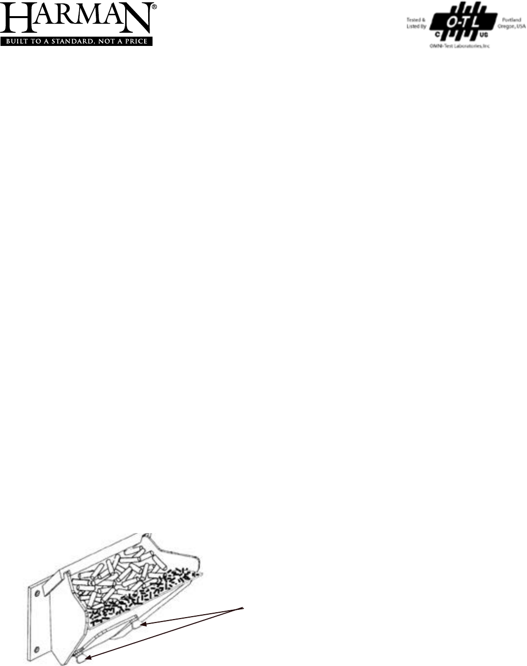
Harman pellet burning, free-standing stoves and inserts have been tested to ASTM E1509 for burning shelled corn
in a mixture with wood pellets. The listing approves up to a 50% corn and 50% pellet mixture. Dierent mixtures of
corn will have distinctively dierent burn characteristics depending upon moisture content and variety. The operator
should closely monitor the stove’s operation when burning a new corn/pellet mixture or a dierent variety of corn,
and make any necessary adjustments to feed rate. Since corn is typically higher in ash and moisture content, cleaning
and ash removal will be needed more frequently.
Operation in Stove Temp mode
Set feed adjuster to # 3. Set temperature knob to #3, Turn mode selector knob onto “Stove Temp” mode. After the re
has lit, watch that the fuel does not feed too fast that it pushes the red glowing fuel bed o of the burn pot grate. If it
does, lower the feed adjuster setting or use a lower percentage of corn in the mixture. After the stove has burned for
10 minutes and the entire fuel bed is burning, the feed adjuster and temperature knobs may be adjusted for higher
heat output if desired. Maximum feed has been reached when the re bed is about ½ to 1 inch from the end of the
burn pot. Settings will vary with dierent types, moisture levels and mix ratios of corn. If you are having diculty burn-
ing a 50% corn / 50% wood pellet mixture, try a lower percentage of corn.
Operation in Room Temp mode
Set feed adjuster to # 2 or # 3. Set temperature knob to desired amount. Turn mode selector knob onto “Room Temp”
mode. After the re has lit, watch that the fuel does not feed too fast that it pushes the red glowing fuel bed o of the
burn pot grate. After the stove has burned for 10 minutes and the entire fuel bed is burning, the feed adjuster may be
set to a higher output level if desired. Maximum feed has been reached when the re bed is about ½ to 1 inch from
the end of the burn pot. It is recommended that after burning at the desired settings, turn the stove o and allow it to
cool, then turn it back on in “Room Temp” mode and watch the stove restart and verify correct operation. Settings will
vary with dierent types, moisture levels and mix ratios of corn. If you are having diculty burning a 50% corn 50%
wood pellet mixture, try a lower percentage of corn.
Changes to Maintenance Schedule
Wood pellets average around 6% moisture content or less. Corn will be 14 or 15% moisture. With more moisture in
the fuel, more maintenance will be incurred. Burn pot scraping may need to be done once per day. The ash pan will ll
more quickly and may need emptied weekly. Most importantly, remove the burn pot cleanout cover weekly to clean
the air passage and the igniter element. Excessive buildup on the igniter may lead to shortened igniter life.
Venting Consideration: Check with your venting manufacturer regarding possible exclusions when a mixture of corn
and pellets is burned.
Addendum for Burning Corn and Pellet Fuel Mixture
Loosen these two wing screws for access
to clean the air passage and igniter.
* For P38+ model, follow Stove Temp instructions. Keep feed rate on #3 or
above when using a wall thermostat.

47
3-90-00674R28_12/13
Service & Maintenance Log
Date Of Service Performed By Description Of Service
Proudly Printed On 100% Recycled Paper
At Harman, we build each product to a standard, not a price.
This powerful heating appliance boasts uncompromising
attention to detail and helps preserve our planet by using
environmentally responsible fuels.
(Signature of Boxer)
Your premium quality hearth product designed and assembled
by the experienced and skilled members at Harman in Halifax,
PA, USA.
