Harman P61A Owner S Manual
2014-07-05
: Harman Harman-P61A-Owner-S-Manual harman-p61a-owner-s-manual harman pdf
Open the PDF directly: View PDF ![]() .
.
Page Count: 42
3-90-05822R29_10/13
SAVE THESE INSTRUCTIONS.
Installation & Operating Manual
SAFETY NOTICE
PLEASE READ THIS ENTIRE MANUAL BEFORE YOU INSTALL AND USE YOUR NEW ROOM HEATER. FAILURE TO
FOLLOW INSTRUCTIONS MAY RESULT IN PROPERTY DAMAGE, BODILY INJURY, OR EVEN DEATH.
FOR USE IN THE U.S. AND CANADA. SUITABLE FOR INSTALLATION IN MOBILE HOMES.
IF THIS HARMAN STOVE IS NOT PROPERLY
INSTALLED, A HOUSE FIRE MAY RESULT. FOR YOUR SAFETY, FOLLOW
INSTALLATION DIRECTIONS. DO NOT USE MAKESHIFT COMPROMISES.
CONTACT LOCAL BUILDING OR FIRE OFFICIALS ABOUT RESTRICTIONS AND INSTALLATION INSPECTION
REQUIREMENTS IN YOUR AREA.
CONTACT YOUR LOCAL AUTHORITY (SUCH AS MUNICIPAL BUILDING DEPARTMENT, FIRE DEPARTMENT, FIRE
PREVENTION BUREAU, ETC.) TO DETERMINE THE NEED FOR A PERMIT.
CETTE GUIDE D'UTILISATION EST DISPONIBLE EN FRANCAIS. CHEZ VOTRE CONCESSIONNAIRE DE HARMAN®.
Model(s):
P61A Freestanding Pellet Stove
NOTICE: SAVE THESE INSTRUCTIONS
Hot glass will cause burns.
• Donottouchglassuntilitiscooled
• NEVERallowchildrentotouchglass
• Keepchildrenaway
• CAREFULLYSUPERVISEchildreninsameroomas
stove.
• Alertchildrenandadultstohazardsofhightemperatures.
High temperatures may ignite clothing or other
ammable materials.
• Keepclothing,furniture,draperiesandotherammable
materialsaway.
HOT SURFACES!
Glassandothersurfacesarehotduring
operationandcooldown.
WARNING
!
To obtain a French translation of this manual, please
contactyourdealerorvisitwww.harmanstoves.com
Pourobtenirunetraductionfrançaisedecemanuel,s’il
vous plaît contacter votre revendeur ou visitez www.
harmanstoves.com
NOTE
Contact your local dealer with questions on installation,
operationorservice.
P61A
Use&CareVideo
3-90-05822R29_10/13
"PREVENT HOUSE FIRES"
Install and Use Only in Accordance With Manufacturer's Installation and Operation Instructions.
Contact Local Building or Fire Offi cials About Restrictions and Installation Inspection in Your Area.
WARNING : THE STRUCTURAL INTEGRITY OF THE MANUFACTURED HOME FLOOR, WALL,
AND CEILING/ROOF MUST BE MAINTAINED. DO NOT INSTALL IN SLEEPING ROOM.
An outside combustion air inlet must be provided. Combustion air should not be obstructed. Refer
to Manufacturer’s instructions and local codes regarding the requirements for passing the exhaust
venting system through a combustible wall or ceiling.
Inspect and Clean Exhaust Venting System Frequently.
Use a 3" or 4" diameter type "L" or "PL" venting system.
Do Not Connect This Unit to a Chimney Flue Serving Another Appliance.
FOR USE WITH WOOD PELLET FUEL OR UP TO 50% CORN / PELLET MIXTURE ONLY.
The Use of Other Fuels May Create an Unsafe Condition.
Input Rating Max: 5.5 lb. fuel/hr.
U.S. Electrical Rating: 115 VAC, 60 Hz, Start 4.2 AMPS, Run 2.8 AMPS
Route Power Cord Away From Unit.
DANGER: Risk of Electrical Shock. Disconnect Power Before Servicing Unit.
For Further Instruction, Refer To Owner's Manual.
Replace glass only with 5mm ceramic available from your dealer.
Keep Viewing and Ash Removal Doors Tightly Closed During Operation.
DO NOT REMOVE THIS LABEL / NE PAS ENLEVER CETTE ÉTIQUETTE
Report #/ Rapport #135-S-22-4, 135-S-22b-6.2
Tested to / Testé à:
ASTM E 1509-04, ULC/ORD-C1482-M1990,
ULC-S627-00
Made in U.S.A. of US and imported parts. / Fabriqué
aux États-Unis-d’Amérique par des pièces d’origine
américaine et pièces importées.
"PREVENTION DES INCENDIES"
Respecter scrupuleusement les instructions du constructeur pour l'installation et les consignes
de fonctionnement. Respecter les règles de sécuritè en vigueur dans votre région.
AVERTISSEMENT POUR MOBILE HOMES: Ne pas installer dans une chambre. ll est imperatif
de prévoir une prise d'alr extérieur. L'intégrité structurale du plancher, du plafond et des murs doit étre
strictement préservée. Se reporter aux instructions du fabricant et aux réglementations spécifi ques
locales concernant les précautions requises lors de la traversée d'un mur ou d'un plafond.
Contróler et nettoyer fréquemment tout le systeme d'evacuation des fumées conformément aux
recommandations du constructeur. Utiliser des tuyaux <<Spécial granulés>> de Ø76 mm ou
102 mm. Ne pas raccorder ce poéle à un conduit de cheminée déjà utilisé pour un autre appareil.
FONCTIONNE EXCLUSIVEMENT AVEC DES GRANULES DE BOIS.
Appareil de chauffage à granulé type. Consommation maximum: 3.63 kg/h.
US coupure: 115 VAC, 60 Hz, 4.2 amps Démarrer, Exécuter 2.8 AMPS
Tenir le cordon d'alimentation à l'écart du poèle.
DANGER: Risque d'électrocution. Débrancher l'appareil avant toute intervention.
Ne remplacer la vitre qu'avec une vitre céramique 5mm de méme qualité disponible
auprès de votre revendeur.
Pour une information plus compléte, se reporter à la notice d'utilisation. Tenir la porte
hermétiquement close durant fonctionnement.
Ne faites pas obstacle l’espace sous le réchauffeur. Toujours fournir un approvisionnement suffi sant en air frais
jusqu’au lieu d’installation Appliance
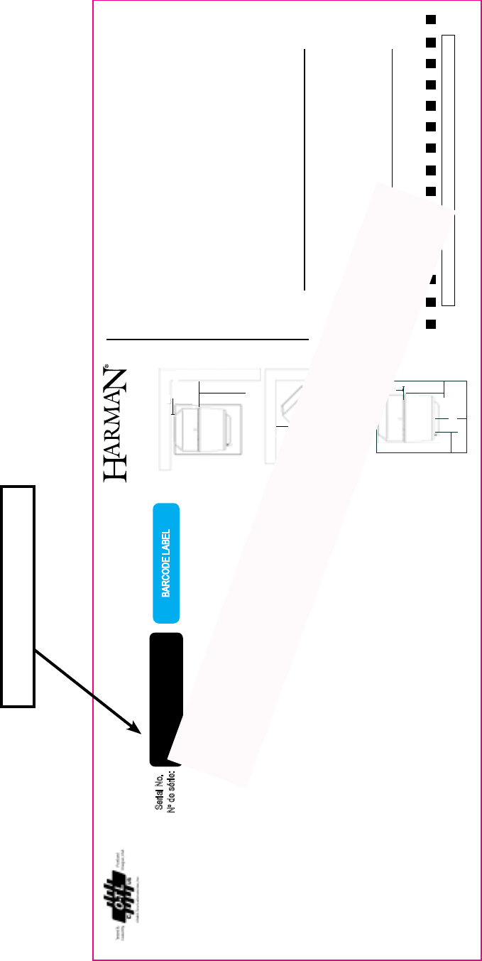
MODEL / Modéle: “P61A”
Room Heater Pellet Fuel Burning Type. Suitable for Mobile-Home Installation.
Appareil de chauffage à granulés de bois Conçu pour maisons mobiles
2"(51mm)
12" (305mm) with side shields
18" (457mm) w/out side shields
9”(228mm)
13”(330mm)
9"(228mm)
13”(330mm)
BARCODE LABEL
MINIMUM CLEARANCES TO COMBUSTIBLES/
DISTANCES DE SECURITE PAR RAPPORT AUX
MATERIAUX COMBUSTIBLES:
Back Wall / Entre Mur Arrière 2”/ 51mm 2”/ 51mm
Side Wall / Entre Paroi Latér 18”/ 457mm 12”/ 305mm
CORNER INSTALLATION / EN ANGLE
Walls to Appliance 13”/330mm 9”/228mm
Entre Murs et appareil
Flue Connector/Raccord à la cheminée 1” /25mm
FLOOR PROTECTION / Protection Du Plancher
USA Canada
Sides*/Côtés (A) 6” 200mm
Back**/Arrière (B) 6” 200mm
Front*/Avant (C) 6” 450mm
**Measured from pedestal base in the US ONLY
**Mesuré à partir de la base du socle aux États-Unis uniquement
*Measured from Glass Opening
*Mesurer à partir de la surface de la porte en verre
Floor Protection Must Be a Non-Combustible Material.
Must Also be Place Under Any Horizontal Flue Connector,
Extending 2” or 51mm Beyond the Pipe Measurement.
Pour protéger le plancher, il faut sous le pêole un matériau. Qui
doit aussi être placé sous les parties horizontales du tuyau de
raccord à la cheminée et s’étendre à 51mm o 2 po. au-delà de
la mesure du tuyau.
WITHOUT
SIDE SHIELDS
WITH
SIDE SHIELDS
Sans Écrans
Latéraux
Avec Écrans
Latéraux
HarmanP61APelletStove
BlackBackgroundwithbaremetalforprint-adhesivebacked,metalplate.
AA C
B
USA CANADA
Floor protector
PROTECTION DE SOL
FLOOR PROTECTION
008
Serial No.
No de série:
Rev EP.N. 3-90-08626
10-3/4"
4-3/8"
Date of Manufacture / Date de fabrication:
2013 2014 2015 JAN FEB MAR APR MAY JUN JUL AUG SEP OCT NOV DEC
Fabriqué par: Hearth and Home Technologies 352 Mountain House Road, Halifax PA 17032
US ENVIRONMENTAL PROTECTION AGENCY
This appliance complies with Canadian Standards Association (CSA) B415.1 and Title 40
of the U.S. Code of Federal Regulations, Part 60, SubPart AAA. This model is exempt from
EPA certifi cation under 40 CFR 60.531 by defi nition [Wood Heater (A) “air-to-fuel ratio”].
Cet appareil est conforme a l’Association Canadienne des Standards (CSA) B415.1-10,
clause 4 et Titre 40 du Code des Régulations Fédérales des États-Unis, partie 60, section
AAA. Ce modèle est exempt de la certifi cation EPA sous 40 CFR 60.531 par défi nition
(Appareil de chauffage au bois (A) “ ratio Air-Combustible).
2
P61APelletStove
The Label Pictured Is For Reference Only. For specic infor-
mation regarding testing and clearances, consult the actual
label on the rear of the stove.
Pleasecopy
yourserial
numberfromthelabel
onyourstovetotheboxbelow.
SERIAL NUMBER
3P61A Pellet Stove 3-90-05822R29_10/13
SafetyInformation 5
Installation 6
Venting 8
ESPControl 15
AutomaticOperation 16
ManualOperation 19
LowDraftVoltageAdjustment 21
Maintenance 22
Troubleshooting 26
FuelSpecications 28
MixingCornwithPellets 29
PowerFailure/Back-up 30
Options 31
WiringDiagram 32
Specications 32
Warranty 33
ServiceParts 35
DivisionofHearth&HomeTechnologies
352MountainHouseRoad
Halifax,PA17032
Table of Contents
Listedby:OMNI-TestLaboratories,Inc.
Report#:135-S-22-4,135-S-22b-6.2
Meetsrequirementsof:ASTME1509-04,ULC/ORD-C1482-
M1990,ULC-S627-00
Thisapplianceisalsoapprovedforinstallationintoashop.
= Contains updated information

4P61A Pellet Stove
3-90-05822R29_10/13
IMPORTANT NOTES
DO NOT INSTALL A FLUE DAMPER IN THE EXHAUST
VENTING SYSTEM OF THIS UNIT.
DO NOT CONNECT THIS UNIT TO A CHIMNEY FLUE
SERVING ANOTHER APPLIANCE.
MOBILE HOME INSTALLATION SHOULD BE DONE IN
ACCORDANCE WITH THE MANUFACTURED HOME
AND SAFETY STANDARD (HUD), CFR 3280, PART 24.
CAUTION
THE STRUCTURAL INTEGRITY OF THE MOBILE
HOME FLOOR, WALL, AND CEILING/ROOF MUST BE
MAINTAINED.
CAUTION
KEEP COMBUSTIBLE MATERIALS (SUCH AS GRASS,
LEAVES, ETC.) AT LEAST 3 FEET AWAY FROM THE
FLUE OUTLET ON THE OUTSIDE OF THE BUILDING.
INSTALLATION AND REPAIR OF THIS HARMAN
STOVE SHOULD BE DONE BY A QUALIFIED SERVICE
PERSON. WE RECOMMEND THAT THE STOVE
BE INSPECTED BEFORE USE AND AT LEAST
ANNUALLY BY A QUALIFIED SERVICE PERSON.
PERIODIC CLEANING IS REQUIRED THROUGHOUT
THE HEATING SEASON AND AT THE END OF EACH
WINTER FOR THE STOVE TO WORK EFFICIENTLY.
REFER TO THE MAINTENANCE SECTION OF THIS
MANUAL.
WARNING
MOBILE/MANUFACTURED HOME STANDARDS DO
NOT ALLOW INSTALLATION IN ROOMS DESIGNATED
FOR SLEEPING.
CAUTION
ALWAYS BE SURE THERE IS NO UNBURNED FUEL IN
THE ASH PAN PRIOR TO LIGHTING A FIRE. THIS WILL
CAUSE SMOKE AND SOOT AND OTHER UNWANTED
RESULTS.
SPECIAL NOTE:
DUE TO FLY ASH BUILDUP, IT IS STRONGLY
RECOMMENDED THAT YOU HAVE YOUR STOVE
PROFESSIONALLY CLEANED AND SERVICED
ANNUALLY. THIS INCLUDES ALL PARTS OF THE
STOVE, AND THE ENTIRE VENTING SYSTEM.
CAUTION
DO NOT USE MAKESHIFT COMPONENTS OR OTHER
COMPROMISES WHEN INSTALLING THIS APPLIANCE.
CAUTION
A CHIMNEY CONNECTOR SHALL NOT PASS
THROUGH AN ATTIC OR ROOF SPACE, CLOSET
OR OTHER CONCEALED SPACE, A FLOOR, OR A
CEILING.
CAUTION
DO NOT CONNECT TO ANY AIR DISTRIBUTION
DUCT OR SYSTEM.
5P61A Pellet Stove 3-90-05822R29_10/13
Assembly and Installation
Unpacking
TheP61Aisbolted(1/4x1"hexheadbolts)totheskidto
preventmovementduringshipping.
Tofreethestovefromtheskidyoumustremovethehold-
downboltsintherearofthepedestalbase.
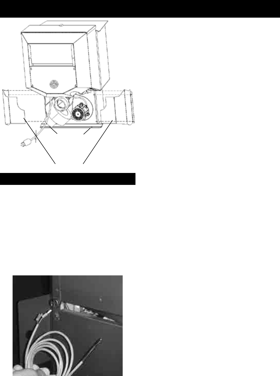
Removing rear cover panels
Therearcoverpanelsaresecuredtothestovewiththree
bolts each. Two of the bolts need only be loosened, not
removed,toremovethepanels.Itisrecommendedthatthe
rearcoversareinstalledaftertheunitisinplaceandthevent
pipeisinstalled,topreventcontactwithhotormovingparts.
Firebrick
Install the three rebricks vertically on the angle bracket
abovetheburnpot.
Flame Guide
Installthecastironameguideontopoftheburnpot.Make
surethattheameguideisfullyseatedontheverticalsides
oftheburnpotandthatthebackoftheguiderestsagainst
thebodyofthestove.
INSTALLEXHAUSTVENTATCLEARANCESSPECIFIED
BYTHEMANUFACTURER.Mostpelletventpiperequiresa
minimumof3"ofclearancetocombustiblematerialsalthough
somecanbeinstalledat1"clearance.
Followtheseinstructionsalongwithalllocalcodesregarding
installationofthisappliance.
Do NOT use makeshift compromises when installing this
appliance,seriousconsequencesmayresult.
Withanyhearthappliance,installationofsmokedetectors
isrecommendedoneverylevelofthehome.
Possible causes of smoke detector activation:
Paintcuringprocess-Openawindowneartheappliance
fortherstfewhoursofburning.
Exhaustbeingdrawnbackinsidethedwelling-Outsideair
connectiontotheapplianceisnecessary.
Ventleakage-Allinteriorseamsandjointsshouldbesealed
withsiliconewhereappliacable.Followventmanufacturers
instructionsforpropersealing.
Theroomsensorisasmalltemperaturesensorontheend
ofa60"wire.Thissensorisinstalledmuchlikeastandard
wallthermostat.Thereisaremoteroomsensorportonthe
rearoftheunitforeasyexternalconnection.Usestandard
18-2thermostatwiretoextendthedistancetothedesired
location(50'maximum).Theroomsensorshouldbeinstalled
inthelocationwhereyouwanttocontrolthetemperature.
NOTE:Distancesofmorethan 25feetfromtheunit orin
another room are not recommended. The room sensor is
essentialfortheP61A'sexcellentefciency.
NOTE: It is recommended that the room sensor be
installed,evenifonlyinstalledontherearoftheunitasa
returnairsensor.
Rear Cover
Panels
Shipping Bolts
Note: These same holes
are used for securing the
stove in mobile home
installation.
Fig. 1
Room Sensor Installation
6P61A Pellet Stove
3-90-05822R29_10/13
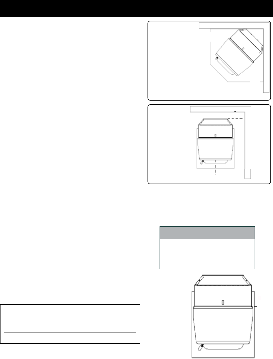
Installing
Placethestoveonanoncombustibleoororonaoorprotector
thatextendsaminimumof6inchestothefront,(measuredfrom
the glass) 6 inches to the sides and 1 inch to the rear of the
hopper.Itisalsorecommendedthatoorprotectionbeinstalled
underanyhorizontalventingandextending2inchesbeyondthe
ventmeasurement.
NOTE for Canadian installation only: Per ULC-S627-00,
If installed on a combustible floor, the need to provide a
noncombustible oor protector covering the area beneath the
space heater andextendingatleast17.72"(450mm)onthering
sideandatleast7.87"(200mm)ontheothersides.
In Canada, you may follow smaller U.S. oor protection
requirements ONLY if the user agrees to completely shut-
down the appliance, and allow it to cool to where all re is
extinguished and the combustion blower and its indicator
light shuts off, prior to opening the rebox door or ash door.
Place the stove away from combustible walls at least as far
asshownin Figures3and 4.Notethe differencein sidewall
clearancewithandwithoutsideshields.
Notethattheclearancesshownareminimumforsafetybutdo
notleavemuchroomforaccesswhencleaningorservicing.
Connect the power cord to a 120 V.A.C. 60Hz grounded
receptacle. (A surge protector is recommended to protect the
circuitboard.)Alsobesurethatthepolarityoftheoutletthatthe
stoveispluggedintoiscorrect.
Prior to installing the ue pipe, connect a draft meter. (The
draft meter must have a minimum range of 0-.5.) Record the
rstreading.Connectuepipetostoveandbesurealldoors
andwindowsinthehomeareclosed.Recordtheseconddraft
reading_______.Ifthesecondreadingismorethan.05"lower
thantherstreading,checkforpossiblerestrictionsortheneed
foroutsideair(seepage9).Formoreinformationonthedraft
testprocedure,refertoPage20.
Mobile Home Installation
Wheninstallingthisunitinamobilehome,severalrequirements
mustbefollowed:
1. Theunitmustbeboltedtotheoor.Thiscanbedonewith
1/4"lagscrewsthroughthe2holesinthebaseplate.
2. Theunitmustalsobeconnectedtooutsideair.Seepage9.
3. Floorprotectionandclearancesmustbefollowedasshown.
4. Unitmustbegroundedtothemetalframeofthemobilehome.
CAUTION: This appliance must be vented to the outside.
Installation
Minimum size rectangular oor protection (USA) is
285/16"DeepBy243/4"Wide.
* Floor protection dimensions for the front and sides
are measured from the appliance door opening in
The United States. In Canada, the side dimension is
measuredfromthewidestpartoftheappliance.
L
J
Floor Protection
Requirements US Canada
Sides
Rear
6" 200mm
6" 200mm
KFront 6" 450mm
Fig. 3
9"(228mm)With Side Shields
13"(330mm) Without Side Shields
Fig. 4
2"(51mm)
36"(914mm)
14" (355mm) with
side shields
20" (508mm)
without side shields
14" (355mm)
20" (508mm)
9"(228mm)-
13"(330mm)
9"(228mm)-
13"(330mm)
Alternate floor protector
dimension may be used
as long as they satisfy the
measurement requirements
shown below.
Minumum size oor protection
for a corner installation hearth
pad is 36" x 36". Clearance
shown as 9" with optional side
shields installed.
J
USA K
L
J
CANADA
NOTE:
Measurement"L"
ismeasuredfrom
thepedestalbase
intheUSONLY
NOTE:
Measurement"K"
ismeasuredfrom
theglassinthe
USONLY
Floor protector
WARNING
THE STRUCTURAL INTEGRITY OF THE MANUFACTURED
HOME FLOOR, WALL, AND CEILING/ROOF MUST BE
MAINTAINED.
DO NOT INSTALL IN SLEEPING ROOM.
7P61A Pellet Stove 3-90-05822R29_10/13
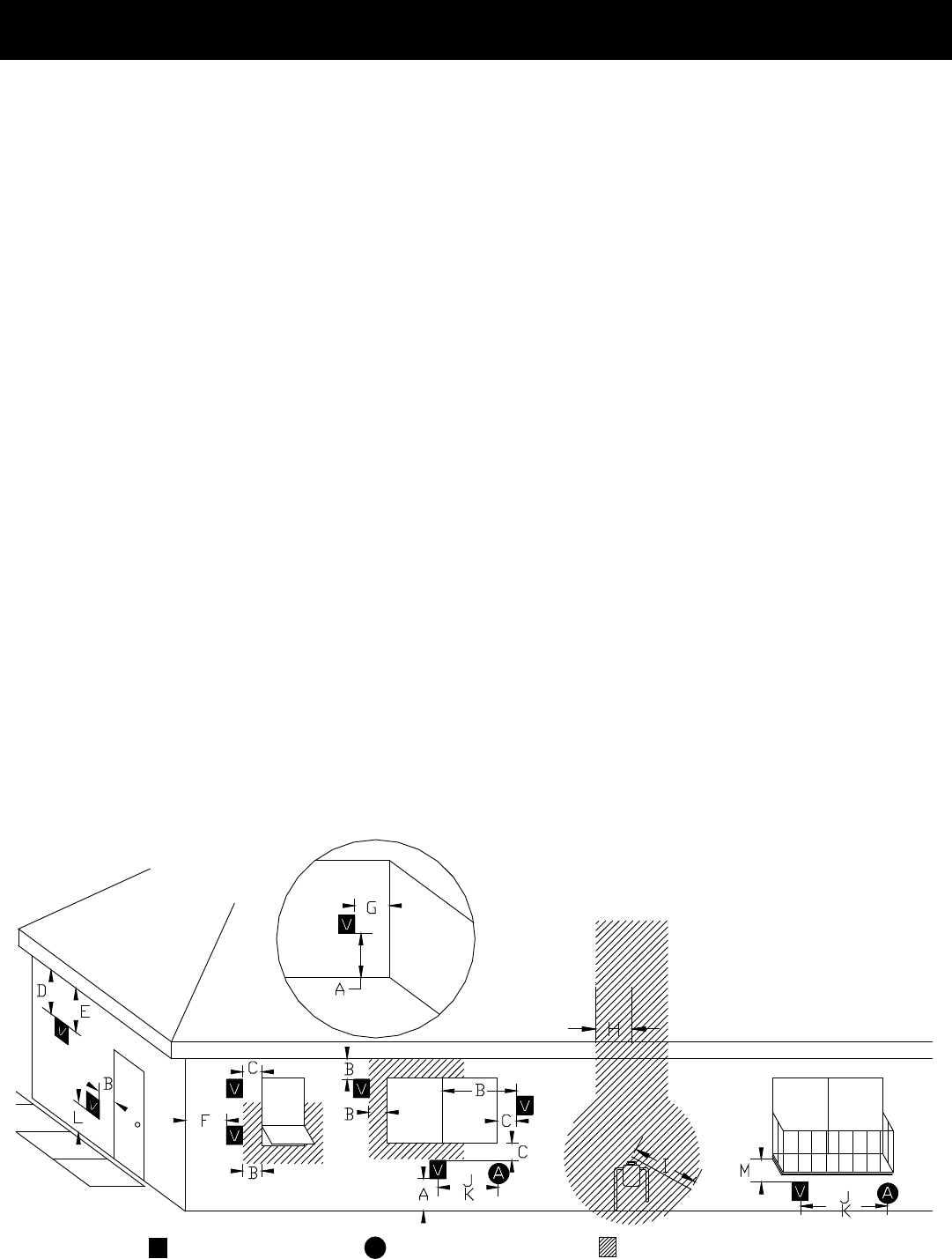
Venting
Requirements for Terminating the Venting
WARNING:Ventingterminalsmustnotberecessedintoa
wallorsiding.
NOTE:Onlyapprovedpelletventpipe,wallpass-throughs,
and fire stops should be used when venting through
combustiblematerials.
NOTE:Always take into consideration the effects of the
prevailing wind direction or other wind currents that may
causeyashand/orsmokewhenplacingtheterminationof
thevent.
In addition, the following must be observed:
A. Theclearanceabovegrademustbeaminimumof12".
B. Theclearancetoawindowordoorthatmaybeopened
must be a minimum of 48" to the side, 48" below the
window/door, and 12" above the window/door. (with
outside air installed, 18” to the side or below)
C.A 12" clearance to a permanently closed window is
recommendedtopreventcondensationonthewindow.
D.Theverticalclearancetoaventilatedsoftlocatedabove
theterminalwithinahorizontaldistanceof2feet(60cm)
fromthecenter-lineoftheterminalmustbeaminimum
of18".
E. Theclearancetoanunventilatedsoftmustbeaminimum
of12".
F. Theclearancetoanoutsidecorneris11"fromcenterof
pipe.
G.Theclearancetoaninsidecorneris12".
H.Aventmustnotbeinstalledwithin3feet(90cm)above
agasmeter/regulatorassemblywhenmeasuredfromthe
horizontalcenter-lineoftheregulator.
I. Theclearancetoserviceregulatorventoutletmustbea
minimumof6feet.
J. Theclearancetoanon-mechanicalairsupplyinlettothe
buildingorthecombustionairinlettoanyotherappliance
mustbeaminimumof48”.
K. Theclearancetoamechanicalairsupplyinletmustbea
minimumof10feet. (with outside air installed, 6 feet )
L. The clearance above a paved sidewalk or a paved
drivewaylocatedonpublicpropertymustbeaminimum
of7feet.
M.Theclearanceunderaveranda,porch,deckorbalcony
mustbeaminimumof12inches. (B. also applies)
NOTE: The clearance to vegetation and other exterior
combustiblessuchasmulchis36”asmeasuredfrom the
centeroftheoutletorcap.This36”radiuscontinuestograde
oraminimumof7feetbelowtheoutlet.
CertainCanadianand/or Localcodesor regulationsmay
requiredifferentclearances.
A vent shall not terminate directly above a side-walk or
paveddrivewaywhichislocatedbetweentwosinglefamily
dwellingsandservesbothdwellings.
Onlypermitted ifveranda, porch, deck, or balconyis fully
openonaminimumof2sidesbeneaththeoor.
NOTE: Where passage through a wall, or partition of
combustible construction is desired, the installation
shall conform to CAN/CSA-B365. (if in Canada)
V=Vent Terminal A=Air Supply Inlet =Area where termination is not permitted
Door
Sidewalk
Fixed
Closed
Openable
Openable Fixed
Closed
Inside Corner
Detail
Porch or
Openable
Deck
or Fixed
8P61A Pellet Stove
3-90-05822R29_10/13
Venting
Venting
A combustion blower is used to extract the combustion
gasesfromtherebox.Thiscausesanegativepressurein
thereboxandapositivepressureintheventingsystemas
showninFig.7.Thelongertheventpipeandmoreelbows
usedinthesystem,thegreatertheowresistance.Because
ofthesefactswerecommendusingasfewelbowsaspossible
and15feetorlessofventpipe.Themaximumhorizontal
runshouldnotexceed48".Ifmorethan15feetofpipeis
needed,theinteriordiametershouldbeincreasedfrom3"to
4"becausealargerpipecauseslessowresistance.Be sure
to use approved pellet vent pipe wall and ceiling pass-
through ttings to go through combustible walls and
ceilings. All joints for connector pipe must be fastened
with a minimum of three screws and a termination cap
must be installed. Follow pellet vent manufacturer
instructions for properly securing each pellet vent joint.
The pellet starting collar must be secured to the unit's
ue collar.
NOTE: Simpson DuraVent PelletVent Pro Harman Adapter
Part #3PVP-ADHB and PelletVent Pro Harman Adapter
Increaser Part #3PVP-X4ADHB are highly recommended
to be installed on the starter collar to insure a proper
pipe connection to the unit.
IMPORTANT NOTICE
Approved3"or4"PelletVentPipeSuchAs,Type"PL",
MustBeUsed.
+
+
-
Fig. 7
Vent Pipe
Pelletventingpipe(knownasPLvent)isconstructedoftwo
layerswithairspacebetweenthelayers.Thisairspaceacts
asaninsulatorandreducestheoutsidesurfacetemperature
toallowaclearancetocombustiblesof1to3inches.The
sections of pipe lock together to form an air tight seal in
mostcases.However,insomecasesaperfectsealisnot
achieved.Forthisreasonandthefactthattheunitoperates
with a positive vent pressure we specify that the joints
also be sealed with high temp (RTV) silicone. Aluminum
tapecanalsobeusedforanyjointthatis1ft.ormorefrom
theoutletofthestove.
Avoiding Smoke and Odors
Negative Pressure, Shut-down, and Power Failure:
To reduce the probability of back-drafting or burn-back in
the pellet burning appliance during power failure or shut-
down conditions, the stove must be able to draft naturally
withoutexhaustbloweroperation.Negativepressureinthe
housewillresistthisnaturaldraftifnotaccountedforinthe
pelletapplianceinstallation.
Heatrisesinthehouseandleaksoutatupperlevels.This
airmustbereplacedwithcoldairfromoutdoors,whichows
into lower levels of the house. Vents and chimneys into
basementsandlowerlevelsofthehousecanbecomethe
conduitforairsupply,andreverseundertheseconditions.
Outside Air:
Hearth & Home Technologies strongly recommends
attaching outside air in all installations, especially lower
level and main oor locations.
A CHIMNEY CONNECTOR MAY NOT PASS THROUGH
AN ATTIC OR ROOF SPACE, CLOSET OR SIMILAR
CONCEALED SPACE, FLOOR , OR CEILING. REFERENCE
LOCAL BUILDING CODES FOR DETAILS.
INSTALL VENT AT CLEARANCES SPECIFIED BY THE
VENT MANUFACTURER
DO NOT INSTALL A FLUE DAMPER IN THE EXHAUST
VENTING SYSTEM OF THIS UNIT.
DO NOT CONNECT THIS UNIT TO A CHIMNEY FLUE
SERVING ANOTHER APPLIANCE
CAUTION
DO NOT USE MAKESHIFT COMPROMISES WHEN
INSTALLING THIS APPLIANCE. DAMAGE AND/OR
INJURY MAY RESULT.
= Positive Static Pressure
= Negative Static Pressure
+
-
9P61A Pellet Stove 3-90-05822R29_10/13
Venting
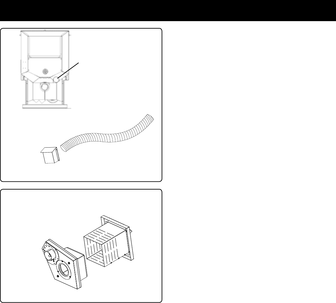
Outside air ex pipe
goes here.
Inlet Cover part#
1-10-08542
Direct Vent Wall Passthrough Kit
(part #1-00-677177)
Vent Congurations:
Toreduceprobabilityofreversedraftingduringshut-downconditions,Hearth&HomeTechnologiesstronglyrecommends:
• Installingthepelletventwithaminimumverticalrunofvefeet,preferablyterminatingabovetheroofline.
• Installingtheoutsideairintakeatleastfourfeetbelowtheventtermination.
Topreventsootdamagetoexteriorwallsofthehouseandtopreventre-entryofsootorashintothehouse:
• Maintainspeciedclearancestowindows,doors,andairinlets,includingairconditioners.
• Ventsshouldnotbeplacedbelowventilatedsofts.Runtheventabovetheroof.
• Avoidventingintoalcovelocations.
• Ventsshouldnotterminateunderoverhangs,decksorontocoveredporches.
• Maintainminimumclearanceof12inchesfromtheventterminationtotheexteriorwall.Ifyouseedepositsdeveloping
onthewall,youmayneedtoextendthisdistancetoaccommodateyourinstallationconditions.
Hearth & Home Technologies assumes no responsibility for, nor does the warranty extend to, smoke damage caused
by reverse drafting of pellet appliances under shut-down or power failure conditions.
Pernationalbuildingcodes,considerationmustbegivento
combustionairsupplytoallcombustionappliances.Failure
tosupplyadequatecombustionairforallappliancedemands,
mayleadtoback-draftingofthoseandotherappliances.
Whentheapplianceisside-wallvented:Theairintakeisbest
locatedonthesameexteriorwallastheexhaustventoutlet
andlocatedloweronthewallthantheexhaustventoutlet.
When the appliance is roof vented: The air intake is best
locatedontheexteriorwallorientedtowardstheprevailing
winddirectionduringtheheatingseason.
Theoutsideairconnectionwillsupplythedemandsofthe
pellet appliance, but consideration must be given to the
totalhouse demand.House demandmay consumesome
airneededforthestove,especiallyduringapowerfailure.It
maybenecessarytoaddadditionalventilationtothespacein
whichthepelletapplianceislocated.Consultwithyourlocal
HVACprofessionaltodeterminetheventilationdemandsfor
yourhouse.
Toinstalloutsideairuse3"non-combustibleexpipe.There
isabreak-awayholeontherearpanelofthestovewhichmust
beremovedtoconnecttheexpipe.Inletcoverpartnumber
1-10-08542shouldbeusedtokeepbirds,rodents,etc.outof
thepipeunlesstheHarmanwallpassthroughisbeingused.
Direct Vent Wall Passthrough
The Harman Direct Vent Wall Passthrough (Part # 1-00-
677177) makes installing your Harman Pellet Stove with
outsideair easier. It combines the needed wall protection
fortheventing,withasourceofintakeairforcombustion.It
ismadetotwallsfrom41/2"to101/8"thickwithasingle
squareopeninginthewallof6-1/2inches.
NOTICE:In Canada,ULC-S627 requiresthat alloutdoor-
airedspaceheatersbesecuredtothestructure.
10P61A Pellet Stove
3-90-05822R29_10/13
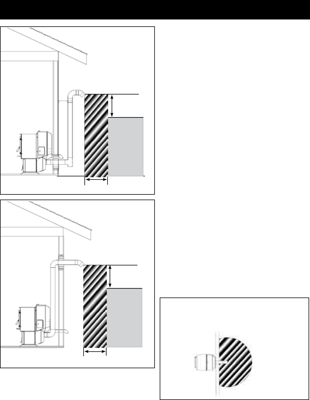
#2 Preferred method
This method also provides excellent venting for normal
operationbutrequiresthestovetobeinstalledfartherfrom
thewall.Theverticalportionoftheventshouldbethreeto
vefeethighandatleastthreeinchesfromacombustible
wall.Thisverticalsectionwillprovidenaturaldraftintheevent
ofapowerfailure.
If the stove is installed below grade be sure the vent
termination is at least 12" above grade. The outlet must also
be 1 foot from the house/building.
Note: Do not place joints within wall pass-throughs.
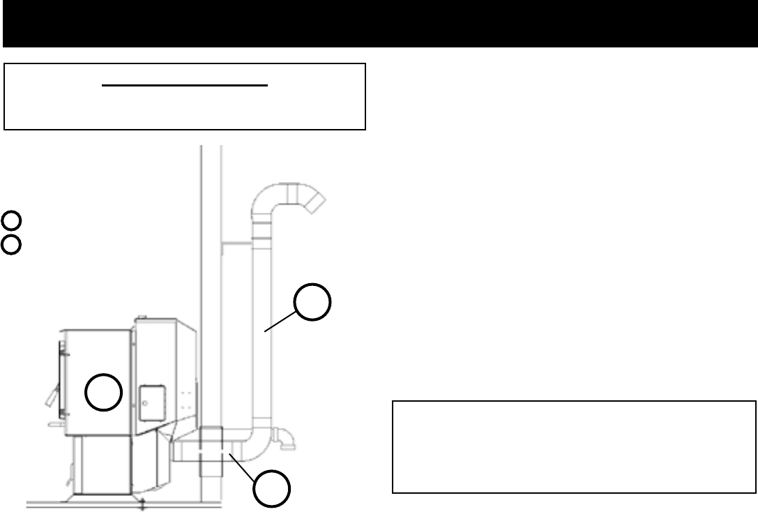
#1 Preferred method
Thismethodprovidesexcellentventingfornormaloperation
andallowsthestovetobeinstalledclosesttothewall.Two
inches from the wall is safe; however, four inches allows
betteraccesstoremovetherearpanel.Theverticalportionof
theventshouldbethreetovefeethigh.Thisverticalsection
willhelpprovidenaturaldraftintheeventofapowerfailure.
Note: Do not place joints within wall pass-throughs.
Venting
Fig. 8 3 ft.
to combustibles
3 ft.
to
combustibles
Fig. 9
3 ft.
to combustibles
3 ft.
to
combustibles
36" min
clearance to any
combustible
material
12" min. wall to outlet
CAUTION
Keep combustible materials (such as grass, leaves, etc.) at
least 3 feet away from the ue outlet on the outside of the
building.
11 P61A Pellet Stove 3-90-05822R29_10/13
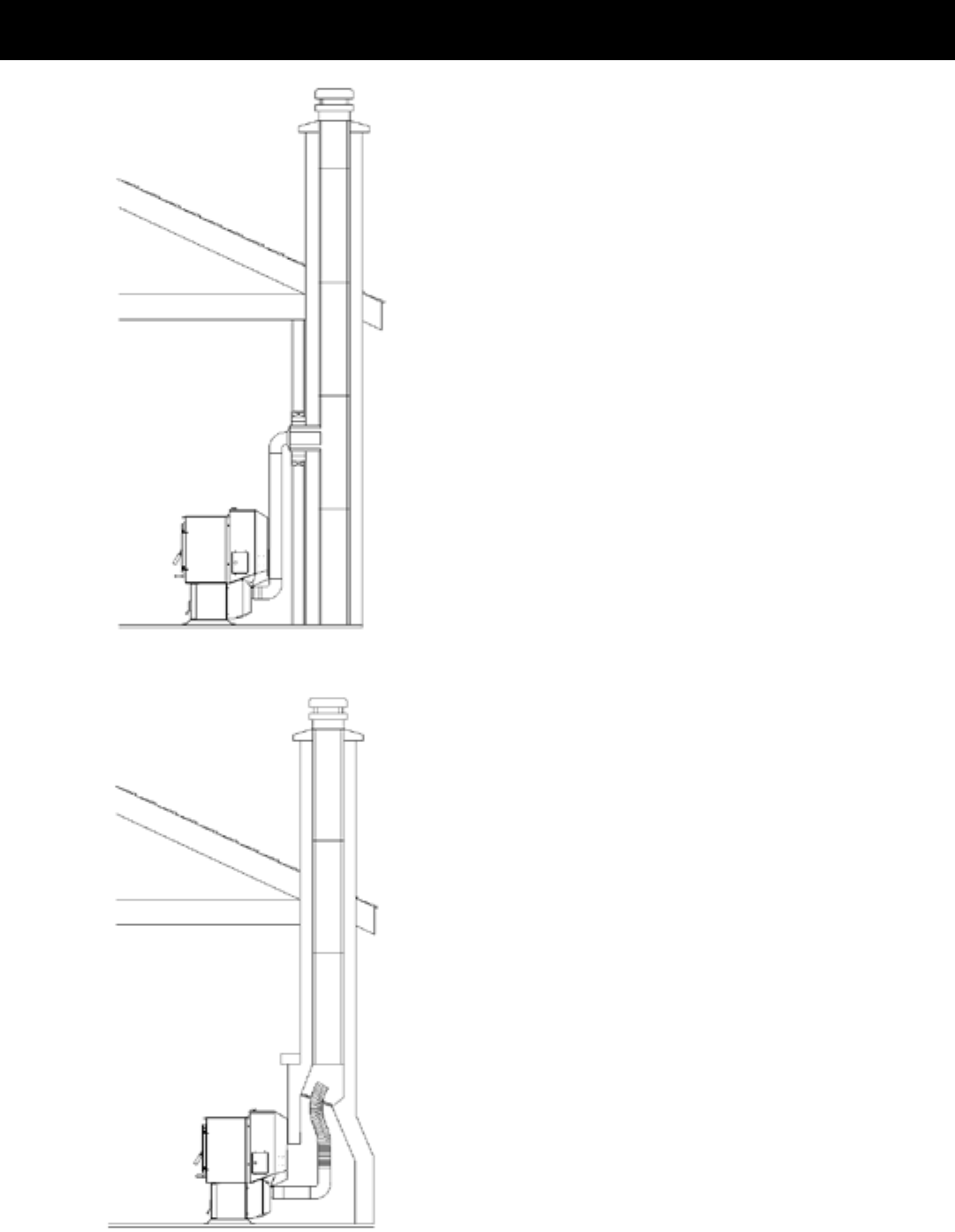
#4 Installing into an existing chimney
Thismethodprovidesexcellentventingfornormaloperation.
This method also provides natural draft in the event of a
powerfailure.Ifthechimneyconditionisquestionable*you
maywanttoinstallalinerasinmethod#7.
InsomeplacesintheUSandCanadaitisrequiredthatthe
ventpipeextendallthewaytothetopofthechimney.
*The chimney should be inspected and cleaned before
installingyourstove.Ifyoudiscoverthatthechimneydoes
nothaveaclaytilelinerorhascracksorakingofthetile
liner you will need to install a stainless steel liner within
thechimney.Inmostcasestheinsidediameterofthisliner
shouldbe4".Eitherexibleorrigidlinermaybeusedfor
thispurpose.RefertoMethod6&7.
Besuretodesigntheventingsothatitcanbeeasilycleaned.
#5 Installing into an existing replace chimney
Thismethodprovidesexcellentventingfornormaloperation.
This method also provides natural draft in the event of a
powerfailure.Ifthechimneyconditionisquestionable*you
maywanttoinstallalinerasinmethod#6.
InsomeplacesintheUSandCanadaitisrequiredthatthe
ventpipeextendallthewaytothetopofthechimney.
*The chimney must be inspected and cleaned before
installingyourstove.Ifyoudiscoverthatthechimneydoes
nothaveaclaytilelinerorhascracksorakingofthetile
lineryouwillneedtoinstallastainlesssteellinerwithinthe
chimney,asshowninMethod6&7.
Thechimneymustbesealedatthe damperusingasteel
plate. Kaowool, mineral wool or other non-combustible
insulation is recommended above the plate to reduce the
possibility of condensation. The connector pipe should
extendthroughthesmokechambertothebaseorintothe
rstuetile.
Besuretodesigntheventingsothatitcanbeeasilycleaned.
Fig. 10
Fig. 11
Venting
12P61A Pellet Stove
3-90-05822R29_10/13
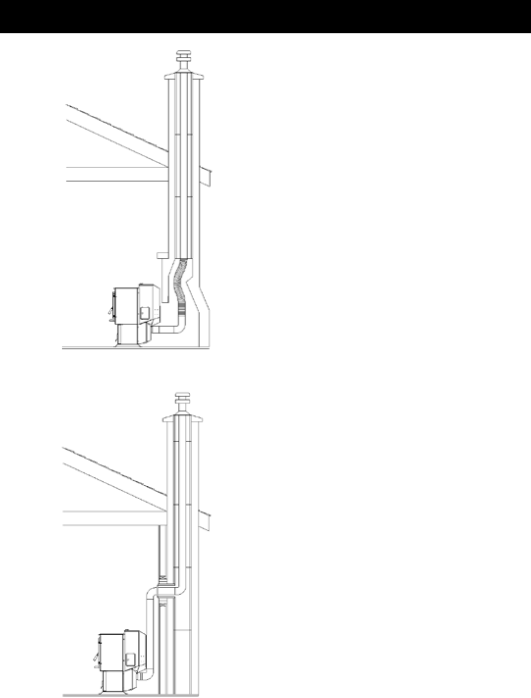
#6 Installing into an existing replace chimney
Thismethodprovidesexcellentventingfornormaloperation.
This method also provides natural draft in the event of a
powerfailure.
InsomeplacesintheUSandCanadaitisrequiredthatthe
ventpipeextendallthewaytothetopofthechimney.The
pipeorlinerinsidethechimneyshouldbe4"diameter.
Inthismethodacapshouldalsobeinstalledonthechimney
tokeepoutrain.Besuretouseapprovedpelletventpipe
ttings. Seal pipe joints with silicone or aluminum tape in
additiontothesealingsystemusedbythemanufacturer.Pipe
sizeshouldbeincreasedto4"usingthismethod.
#7 Installing into an existing chimney
Thismethodprovidesexcellentventingfornormaloperation.
This method also provides natural draft in the event of a
powerfailure.
InsomeplacesintheUSandCanadaitisrequiredthatthe
ventpipeextendallthewaytothetopofthechimney.The
pipeorlinerinsidethechimneyshouldbe4"diameter.
Inthismethodacapshouldalsobeinstalledonthechimney
tokeepoutrain.
Fig. 12
Fig. 13
Venting
13 P61A Pellet Stove 3-90-05822R29_10/13
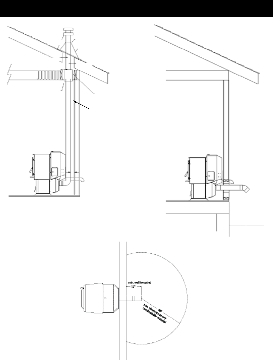
#8 Installing through the ceiling
Through the ceiling vent, follow PL vent manufacturers
recommendationswhenusingwallandceilingpassthrough. Note:
Do not place joints within wall pass-throughs.
Fig. 14
PL vent manufacturer's
restop spacer and support
(See Page 7 for
corner installation
clearances)
Minimum ue vent conguration
It is recommended that outside
air be installed with this venting
configuration to reduce smoke
andcreosotesmellintheroomin
theeventofpowerfailure.
Min. above ground level
12"
Storm collar
Flashing
1"min. 1"min.
12"min.
1"min.
Venting
Fig. 15
1"min.
No insulation or
other combustible
materials are
allowed within
1" of the pellet
vent pipe. Unless
specied by the
pipe manufacturer
Fig. 16
14P61A Pellet Stove
3-90-05822R29_10/13
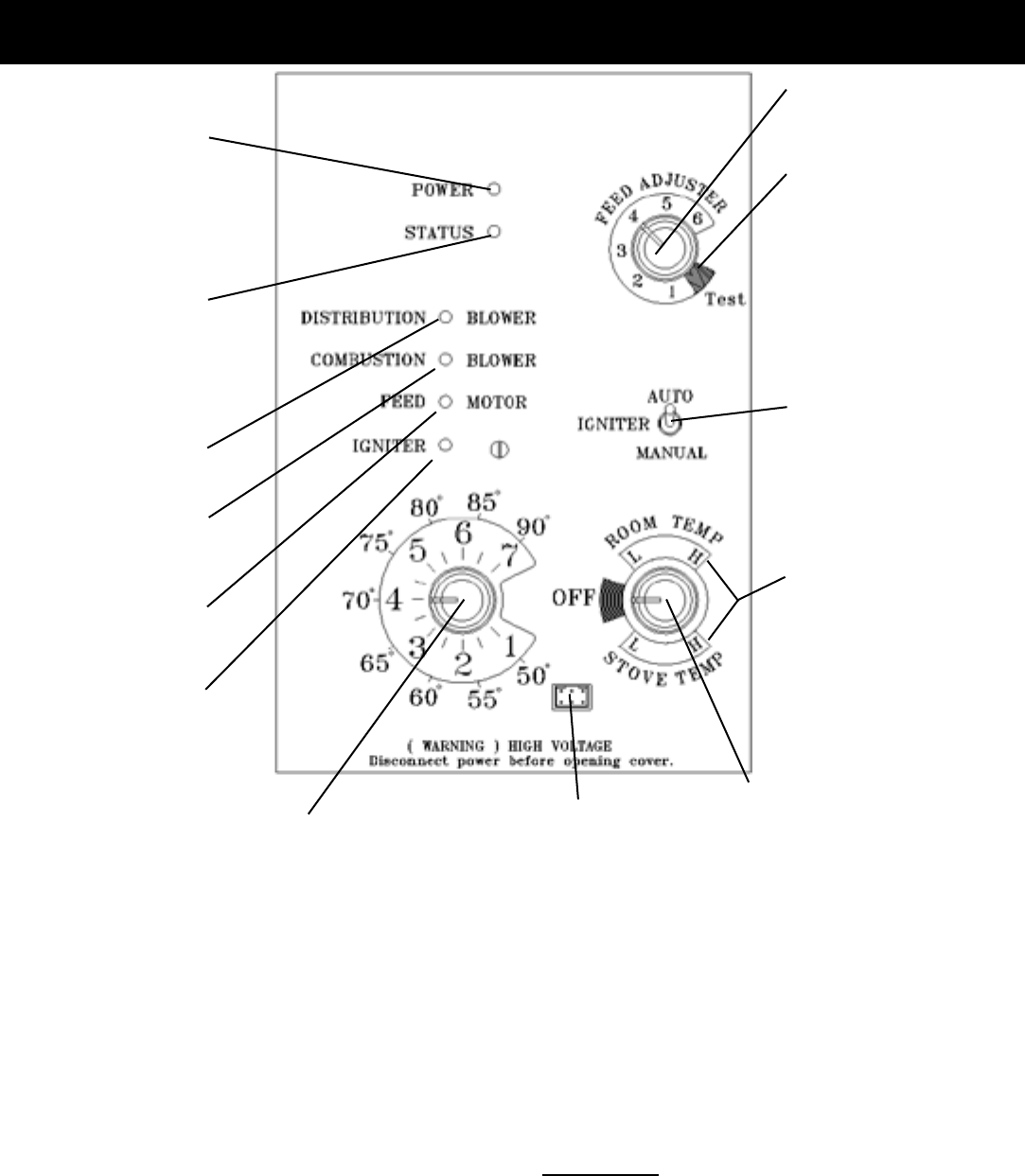
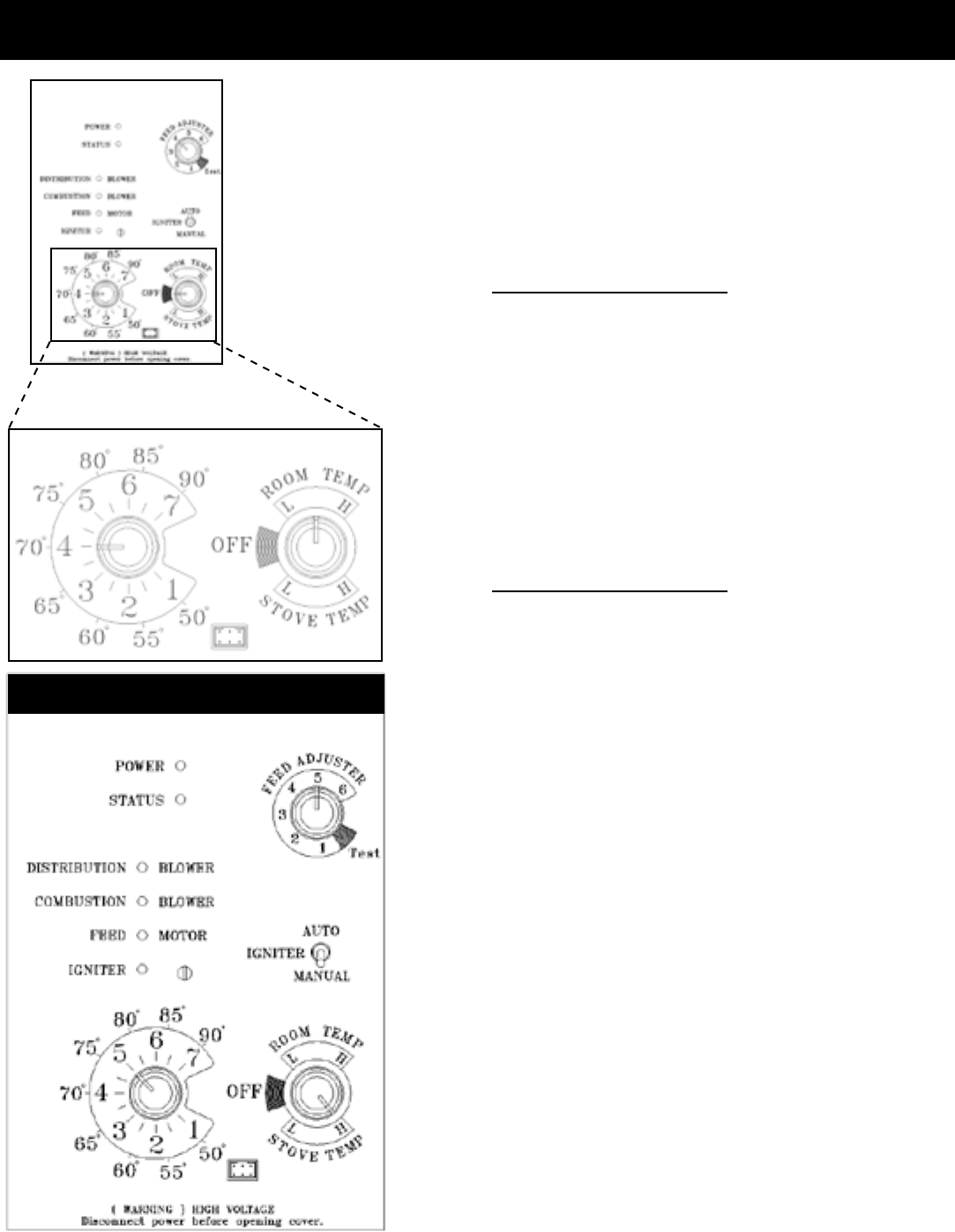
AUTOMATIC IGNITION ESP CONTROL
Feed adjuster
Sets the maximum feed
rate.
Test
Runs all motors at full
speed for one minute to
check operation. Afterward
the control will simulate
a minimum burn and the
combustion blower will
remain on low, with the
distribution blower on high.
Distribution Blower speed
adjustment range.
L = low
H = high
Variable speed anywhere
between L and H; although
as the stove temp. goes up
, so does the low end of the
scale.
Temp dial
Allows you to adjust the room temperature in Room
Temp Mode using the outer scale marked in degrees
Fahrenheit. It also allows you to adjust the stove
temperature while in Stove Temp Mode using the inner
scale marked from 1 to 7.
Mode Selector
Allows you to choose between
Room Temp Mode, Stove Temp
Mode, or OFF. Also allows you to
vary the distribution blower speed
by turning the knob to the high or
low side of each mode.
Power Light
Indicates power to the
control.
Indicates power to the
feed motor.
Indicates power to the
igniter.
Indicates power to
combustion blower.
Status Light
Will be lit in either stove
or room temp mode when
pointer is not within off
position band except after
normal shut down. Blinks
to indicate errors listed
below.
Indicates power to
distribution blower.
Status light error messages:
3 Blinks:IndicatesthattheESP(ExhaustSensingProbe)
haslostcommunicationwiththecircuitboard,orhasgone
outofrangemorethanallowedinaspeciedtime.Iftheunit
seemstobeoperatingproperly,performamanualreset*.If
thecodepersists,contactyourdealer.
4 Blinks: Can occur only in Room Temp Mode and
indicatesRoom SensingProbe failed ornot installed.If a
RoomSensingProbeistheninstalled,thestatuslightwill
automaticallyreset.
5 Blinks (In Igniter Auto. Mode Only):Indicatesthattheunit
hasfailedtolightwithinthe36minutestartcycle.Toreset-
TurnModeSelectorto"OFF",thenturntoeithermodeagain.
6 Blinks :Indicatesthatthecontrolhascalculatedpooror
incompletecombustionoccurringformorethan25minutes.
Asixblinkstatusmaybesetifthestoveisallowedtorunout
ofpellets.Toreset,turnmodeselectorto"OFF"thenback
ontothedesiredmode.Iftheunitwasnotoutofpellets,see
Troubleshootingsectionformoredetails.
* Manual reset-disconnectpowercordforafewseconds
andreconnect.IferrorstilloccurscallyourDealer.
Dealer Diagnostic Port
For dealer maintenance
only. Requires special DDM
monitor supplied to Harman
Dealers exclusively.
Igniter switch
Set to appropriate Start-Up
mode.
15 P61A Pellet Stove 3-90-05822R29_10/13
AUTOMATIC IGNITION/OPERATION
The P61A is a fully automatic stove that features two
operating modes; Stove Temperature Mode and Room
Temperature Mode.InStoveTemperatureMode,youselect
aburnrateandthestovewillremainatthesameburnrate
regardlessoftheroomtemperature.
IntheRoomTemperatureModethestoveconstantlymonitors
thetemperatureintheroomandadjuststhesizeofthere
andtheheatoutputofthestovesothattheroomiskeptat
aconstanttemperature.Roommode,intheAUTOposition,
hastheaddedadvantageofturningthestoveoffifnoheat
isrequiredandturningthestoveonagainwhentheroom
temperaturedropsbelowyourdesiredroomtemperature.
Room Temperature Mode
Most consumers use the stove in the Room Temperature
Modebecauseit istheeasiest andmostefcient method
ofkeepingtheroomatagiventemperature.IntheRoom
Temperature Mode, the Room Sensing Probe constantly
monitorsroomtemperature.Astheweatherchangesoutside
andyourhomeneedsvaryingamountsofheattobeata
desiredtemperature,thestovewillautomaticallyincreasere
sizeandheatoutputsothataconstanteventemperatureis
maintained.Iftheweatherwarmsupandnoheatisrequired,
thestovewillgraduallyshutdown.Whenthehousecools
down,thestovewillautomaticallybringtheroomtemperature
totheprecisetemperatureyoudesire.
IntheRoomTemperatureModeyoucanselecteitherAuto
or Manual modesfortheigniter,usingtheignitertoggle
switch.WhenthetoggleswitchisintheAutoposition,the
igniter,locatedinsidetheburnpot,isreadytoautomatically
lighttherewhenrequired.Whenthetoggleswitchsettothe
Manualpositionthestovecanbelitmanuallywitheitheragel
orawaxtyperestarter.(seelightinginstructionsonpage
19.)WiththeignitertoggleswitchsetintheManualposition
thestovewillautomaticallyadjustheatoutput,butthestove
willnotautomaticallyshutdownifnoheatisrequired.Instead
itwillgotoitslowestsettingandremainthere.TheManual
positionontheignitertoggleswitchletsyoulightthestove
manually,shouldtheigniterfailforanyreason.Secondlyif
youareusingtheHarmanbatterybackupsystem,theManual
settingwillpreventthestovefromturningoffandonduring
apowerfailure,whichwoulddrainthebackupbattery,and
possiblycausedamagetotheback-uporthestove.
IntheRoomTemperatureMode,thedistributionblowerspeed
canbeincreasedordecreasedbyadjustingtheRoomTemp/
Off/StoveTempdialbetweenLandH.Asoutputofthestove
increases,thespeedoftheblowerwillincreaseautomatically
toinsurethatmoreheatistransferredoutintotheroom.The
distributionblowerwillshutoffastheroomreachestheset
temperature,thiswillpreventoverheatingoftheroom.
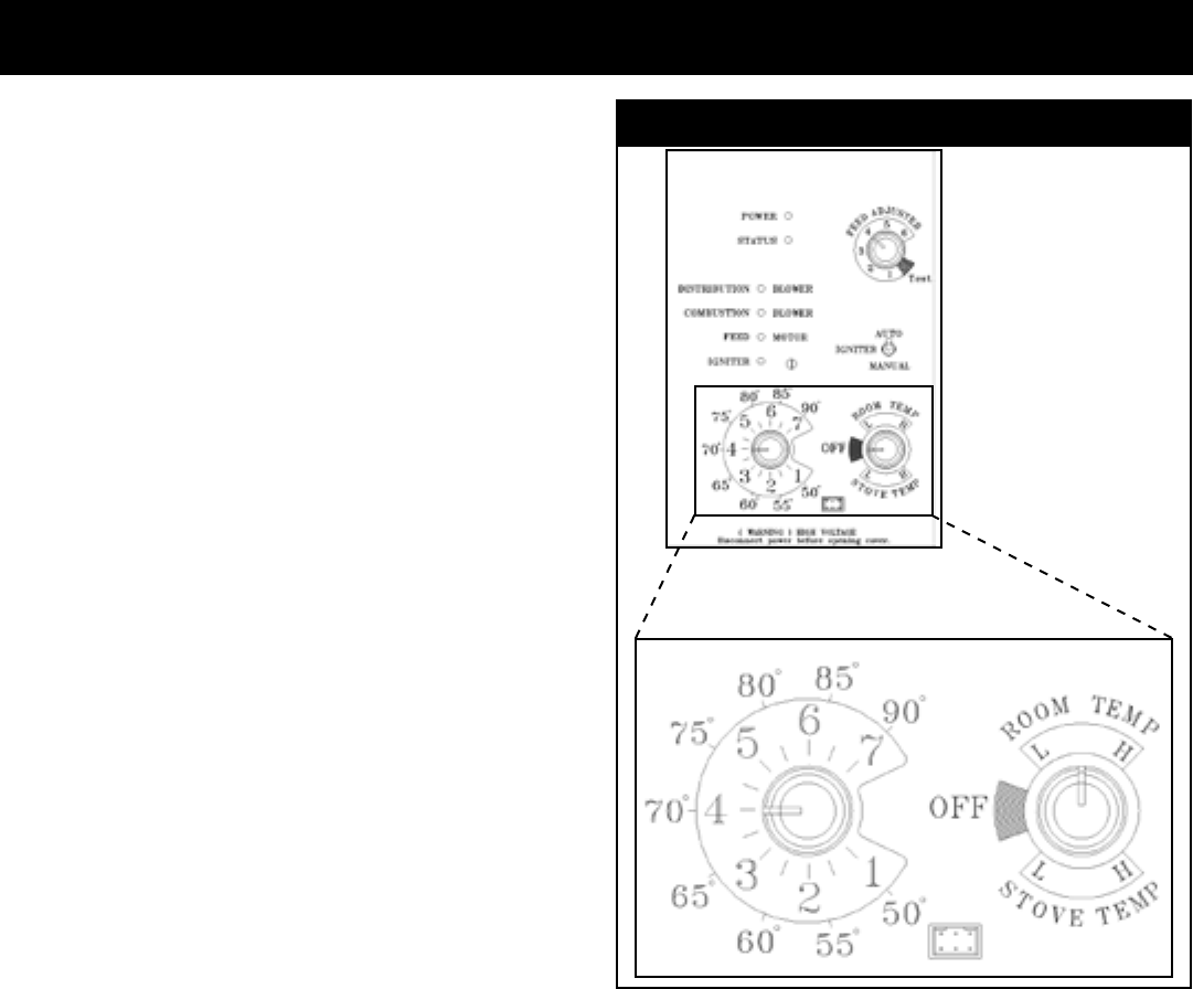
Room Temperature Mode: Thissetting,seeabove,willproduce
aroomtemperatureof70degreeswiththedistributionblowerat
mediumspeed.
Room Temperature Mode
CAUTION:
DO NOT CONNECTTOANYAIR DISTRIBUTION DUCT
ORSYSTEM.
DO NOT BURN GARBAGE OR FLAMMABLE FLUIDS
SUCHASGASOLINE,NAPTHA,ORENGINEOIL.
HOT WHILE IN OPERATION. KEEP CHILDREN,
CLOTHING, AND FURNITURE AWAY. CONTACT MAY
CAUSESKINBURNS.
KEEP FIREBOXANDASH REMOVAL DOORS CLOSED
DURING OPERATION. MAINTAIN SEALS IN GOOD
CONDITION.
16P61A Pellet Stove
3-90-05822R29_10/13
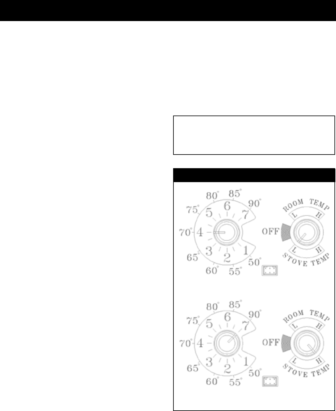
AUTOMATIC IGNITION/OPERATION
The setting above will produce continuous maximum heat
output with the distribution blower at full speed.
Stove Temperature Mode
The setting above will produce continuous medium heat output
with the distribution blower at low speed.
CAUTION
HOT WHILE IN OPERATION. KEEP CHILDREN,
CLOTHING, AND FURNITURE AWAY. CONTACT MAY
CAUSE SKIN BURNS.
Shut Down Procedure
The best way to shut down the stove is to simply let it
runout ofpellets.Thestove willshut downautomatically.
Alternatively,youcanturntheModeSelectorto“off”.This
willcausetheretograduallydiedownandgoout.There
willnotgooutimmediatelyandmaytakemorethananhour
tofullyshutdown.
Ifthestoveislefttorunoutoffuel,youmaygeta6blink
statuslight.Ifthishappenssimplyresetthecontrolboardby
turningthemodeselectortoOFFandbackON.
Stove Temperature Mode
IntheStoveTemperatureModeandwiththeignitertoggle
switchintheAutoposition,thestovewilllightautomatically
andcanbeadjustedtothedesiredsettingusingthesame
temperaturecontroldialasisusedintheRoomTemperature
Mode. The heat output and fuel consumption will remain
constantregardlessofroomtemperature.Thesettingsfrom
1to7ontheinnerringofthetemperaturedialprovidefor
relativeheatoutputsettingswith1being lowand7being
themaximum.
InStoveTemperatureMode,thestovewillnotautomatically
shutoffunlessthestoverunsoutoffueloristurnedoff.
Neverpulltheplugtoshutdownthestove.Thiswillstopthe
combustionblowerandsmokewillescapethroughwindow
anddoorgaskets.
Whentheignitertoggleswitchissettomanualinthismode,
thedistributionblowerwillnotturnonwithatemperaturedial
settingfrom1to5.Theadvantageofthismodeistoallow
theoperatortohavealargeviewingrewithoutblowingextra
heatintotheroom.
During manual operation, with the temperature dial set
at #4 or less, the distribution fan will not operate.A #4
on the temperature dial and a #5 on the feed adjuster is
approximately80%output.Itisnotnecessarytooperatethe
distributionblowerbelowthispoint.Therefore,thecontrol
allowsahigherburnrate(alargerviewingre)withoutan
excessofhotairblowingintotheroom.
AnexampleofwhentousetheManualStoveTemperature
Modeisif youwant towatch alarge reandthe roomis
alreadyuptotemperature.TheStoveTemperatureMode
allows you to have a larger re and a lower sound level,
withoutthedistributionblower.
NOTE:Duringtheuseofthismode,ifyoukeepincreasing
the temperature dial setting to increase the re size, the
distributionblowerwillautomaticallycomeonwhentheESP
Temperaturereaches350oF,or81%output.
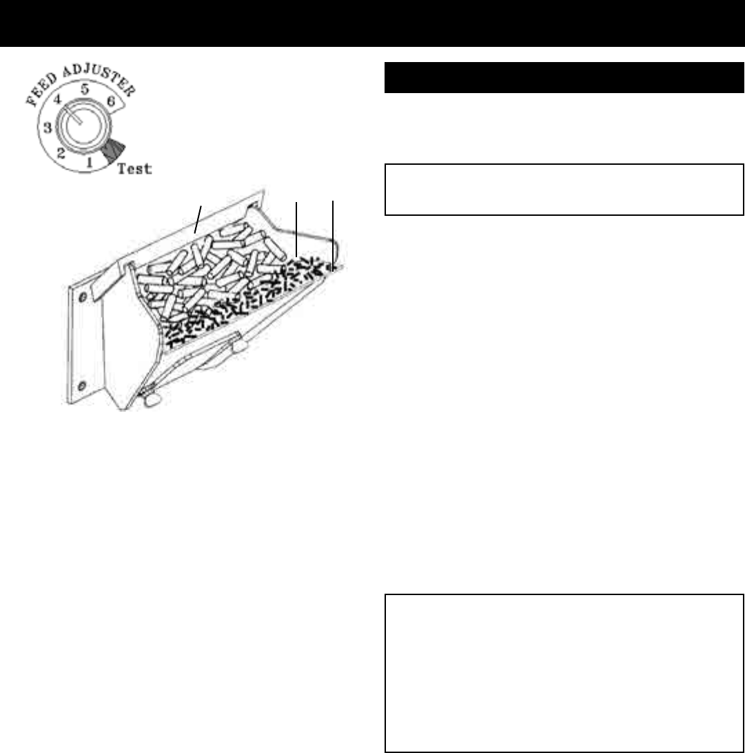
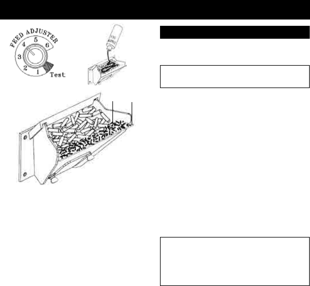
Feed Adjuster Knob
FormostpremiumgradepelletfuelstheFeedAdjusterKnob
shouldbesetat4.Ifhigherashfuelsareusedthesetting
should be increased to 5 or 6. Also higher settings are
requiredifyouwouldliketogetthemaximumheatoutputfrom
thestove.Atthemaximumburnrate(withthetemperature
dialon7/90°andthefeedadjusterat6)thereshouldbe1"or
moreofashonthefrontoftheburnpot.Ifthereislessthan
1"ofash,turnthefeedadjusterknobdowntoalowersetting.
17 P61A Pellet Stove 3-90-05822R29_10/13
Igniter Switch to "AUTO" (up position)
Makesuretheunitispluggedintoa120VAC,60HZelectrical
source.Thepowerlightshouldbetheonlylightlit.
AUTOMATIC START UP
Helpful Hints
1. Fines are small pieces of broken pellets (sawdust). Fines do not
ow easily and often build up on the hopper funnel bottom angles.
You can push these nes into the feeder opening and then ll the
hopper with pellets. As the system works, they will be burned. Or
you can clean them out before lling the hopper.
2. The "TEST" cycle will operate the feeder motor for exactly one
minute. Turning to "TEST" again and again may charge too much
fuel into the burn pot causing excessive smoke on start-up.
3. The rebox low pressure switch will not allow the auger motor
or the igniter element to operate if the view door or the ash pan
door are open.
4. Adjust Feed Rate. If this is your rst re or you are trying different
pellets, set the feed adjuster to #4, Fig. 17. This is a conservative
number and will probably need to be increased. After you know a
feed rate setting that works well, use that setting. Remember, if your
feed rate is too high you may waste fuel.
5. This is usually a weekly maintenance procedure. Cleaning the
burn pot with the scraper with a small amount of new fuel in the
bottom is not a problem. First, scrape the ashes off the front of the
burn pot into the ash pan. Then, scrape the top surface of the burn
pot downward into the base of the burn pot. When the stove is
ignited these scrapings will be pushed out by the feeder and burned.
6. The ash pan can hold the ashes from approximately 1 ton of
premium fuel. This means the ashes will only need to be emptied
a few times each year.
7. Setting the feed adjuster # for maximum burn: With the unit
burning in "AUTO", turn to "Stove Mode" and put the fan on "H".
Set the Temperature Dial to #7. Allow the unit to burn for about 30
minutes and check ash on front of burn pot. Fig. 18. If the ash line
is larger than 1", turn the feed adjuster from #4 to #5. Allow another
30 minutes of burn time and check again. If , at #6 setting, a 1" or
less ash bed is not obtainable, it is not a problem. The 1" ash bed
is only a maximum burn rate and at most normal settings the ash
bed will be larger.
See Hint #7.
Fig. 18
1"
Flame Guide
Starting First Fire
NOTICE: Be sure there is no unburned fuel or other
combustibles in the ash pan prior to lighting.
CAUTION
DO NOT USE CHEMICALS OR FLUIDS TO START
THE FIRE. FOR EXAMPLE: NEVER USE GASOLINE,
GASOLINE-TYPE LANTERN FUEL, KEROSENE,
CHARCOAL LIGHTER FLUID, OR SIMILAR LIQUIDS TO
START OR "FRESHEN UP" A FIRE IN THIS HEATER.
KEEP ALL SUCH LIQUIDS WELL AWAY FROM THE
HEATER WHILE IT IS IN USE.
1. Turn Mode Selector to "OFF".
2. Fill hopperwithpellets.
3. Clean burn pot withscraper,ifnecessary.
4. If starting after an empty hopper, turn Feed Adjuster
to "TEST" (forone60secondcycle).Thiswillfeedpellets
intotheaugertubeandalsoallowyoutocheckthemotors
foroperation.
NOTE: The auger motor will not operate with the view
door or ash pan door open.
5. Turn Feed Adjuster to #4.
6. Flip the Igniter Switch up intothe"AUTO"position.
7. Turn the Temperature Dial tothedesiredtemperature.
8. Turn Mode Selector to Room Temperature or Stove
Temperature.
9. Fill hopper withpelletsandremove ashesasrequired.
KEEP THE APPLIANCE DOORS AND HOPPER LID
CLOSED DURING OPERATION.
Fig. 17
18P61A Pellet Stove
3-90-05822R29_10/13
TheP61APelletStoveiscapableofmanualoperation.Thisalsoallowstheoperatortomanually
controloperationduringanemergency(i.e.igniterfailure,whenusinga502Hbatterybackup,
asopposedtothe512H,orwhenusingcertaingenerators.)
Theunitcanbeswitchedbetween"AUTO"and"MANUAL"atanytimeduringoperation.
Igniter Switch to "MANUAL"
Room Temperature Mode
Therewillhavetobelitwithstartinggelandamatch,or
startedautomatically,see"AutomaticOperation"onPage16.
Turnto"Manual"positionwhentheignitioncyclehasstarted.
Thedifferencebetween"AUTO"RoomTemperatureMode
and"Manual"RoomTemperatureModeisthattherewill
notgooutastheroomtemperaturegoesabovethecontrol
boardsetting.Theunitcanonlygotolowburnandwillremain
thereuntil it runs outof fuel or until moreheat is needed
andthefeedrateincreases.Feedrateadjustmentsanddial
settingsarethesameas"AUTO"settings.Theblowerwill
shutoffcompletelyifthetemperatureontheESPistoolow.
Igniter Switch to "MANUAL"
Stove Temperature Mode
Theadvantageofthismodeistoallowtheoperatortohave
alargeviewingrewithoutblowingextraheatintotheroom.
Duringoperation,withthetemperaturedialsetat#5orless,
thedistributionfanwillnotoperate.A#5onthetemperature
dial and a #5 on the feed adjuster is approximately 80%
output.Itisnotnecessarytooperatethedistributionblower
belowthispoint.Thiscontrolsettingallowsahigherburnrate
(alargerviewingre)withoutanexcessofhotairblowing
intotheroom.
AnexampleofwhentousetheManualStoveTemperature
Modeisif youwant towatch alarge reandthe roomis
alreadyuptotemperature.TheStoveTemperatureMode
allows you to have a larger re and a lower sound level,
withoutthedistributionblower.
NOTE: During the use of this mode, if you keep increasing
the temperature dial setting to increase the re size, the
distribution blower will automatically come on when the
ESP Temperature reaches 350o F, or 81% output.
NOTE: When starting the unit in the "AUTO" mode and
switching to "MANUAL", the ignition cycle must be
allowed to begin prior to making the switch.
MANUAL IGNITION/OPERATION
This setting will produce a large viewing re without a
distribution blower operating.
Manual Stove Temperature Mode
Room Temperature Mode: This
setting, see below, will produce a
room temperature of 70 degrees
with the distribution blower at
medium speed.
19 P61A Pellet Stove 3-90-05822R29_10/13
MANUAL START UP
Igniter Switch to "MANUAL" (down position)
Makesuretheunitispluggedintoa120VAC,60HZelectrical
source.Thepowerlightshouldbetheonlylightlit.
1. Turn FEED ADJUSTER to desired feed rate.No.4is
goodformostpellets.
2. Turn the MODE SELECTOR to “OFF” and then to
the desired mode.Thiswillresetcontrolandstartthe
combustionmotor.
3. Turn the TEMPERATURE DIAL to the desired setting.
4. Clean burn pot with scraper if necessary.
5. Fill burn pot with pellets, only level with front edge.
(DoNotOverFill).
6. Add starting gel on top of the pellets.Stirgelintopellets
forfastlighting.
7. Light starting gel with a match, and close the door.
Operation will begin when the re reaches the proper
temperature.
8. Fill hopper with pellets and remove ashes as required.
KEEP THE APPLIANCE DOORS AND HOPPER LID
CLOSED DURING OPERATION.
WARNING
"NEVER USE GASOLINE, GASOLINE-TYPE LANTERN
FUEL, KEROSENE, CHARCOAL LIGHTER FLUID, OR
SIMILAR LIQUIDS TO START OR "FRESHEN UP "
A FIRE IN THIS HEATER. KEEP ALL SUCH LIQUIDS
WELL AWAY FROM THE HEATER WHILE IN USE".
Helpful Hints
1. Fines are small pieces of broken pellets (sawdust). Fines do not
ow easily and often build up on the hopper funnel bottom angles.
You can push these nes into the feeder opening and then ll the
hopper with pellets. As the system works, they will be burned. Or
you can clean them out before lling the hopper. As the system
works, they will be burned.
2. The "TEST" cycle will operate the feeder motor for exactly one
minute. Turning to "TEST" again and again may charge too much
fuel into the burn pot causing excessive smoke on start-up.
3. The rebox low pressure switch will not allow the auger motor
or the igniter element to operate if the view door or the ash pan
door are open.
4. Adjust Feed Rate. If this is your rst re or you are trying different
pellets, set the feed adjuster to #4, Fig. 19. This is a conservative
number and will probably need to be increased. After you know a
feed rate setting that works well, use that setting. Remember, if your
feed rate is too high you may waste fuel.
5. This is usually a weekly maintenance procedure. Cleaning the
burn pot with the scraper with a small amount of new fuel in the
bottom is not a problem. First, scrape the ashes off the front of the
burn pot into the ash pan. Then, scrape the top surface of the burn
pot downward into the base of the burn pot. When the stove is
ignited these scrapings will be pushed out by the feeder and burned.
6. The ash pan can hold the ashes from approximately 1 ton of
premium fuel. This means the ashes will only need to be emptied
a few times each year.
7. Setting the feed adjuster # for maximum burn: With the unit
burning in "AUTO", turn to "Stove Mode" and put the fan on "H".
Set the Temperature Dial to #7. Allow the unit to burn for about 30
minutes and check ash on front of burn pot. Fig. 21. If the ash line
is larger than 1", turn the feed adjuster from #3 to #4. Allow another
30 minutes of burn time and check again. If , at #6 setting, a 1" or
less ash bed is not obtainable, it is not a problem. The 1" ash bed
is only a maximum burn rate and at most normal settings the ash
bed will be larger.
Fig. 20
Fig. 19
Fig. 21
1"
See Hint #7.
Starting First Fire
NOTICE: Be sure there is no unburned fuel or other
combustibles in the ash pan prior to lighting.
20P61A Pellet Stove
3-90-05822R29_10/13
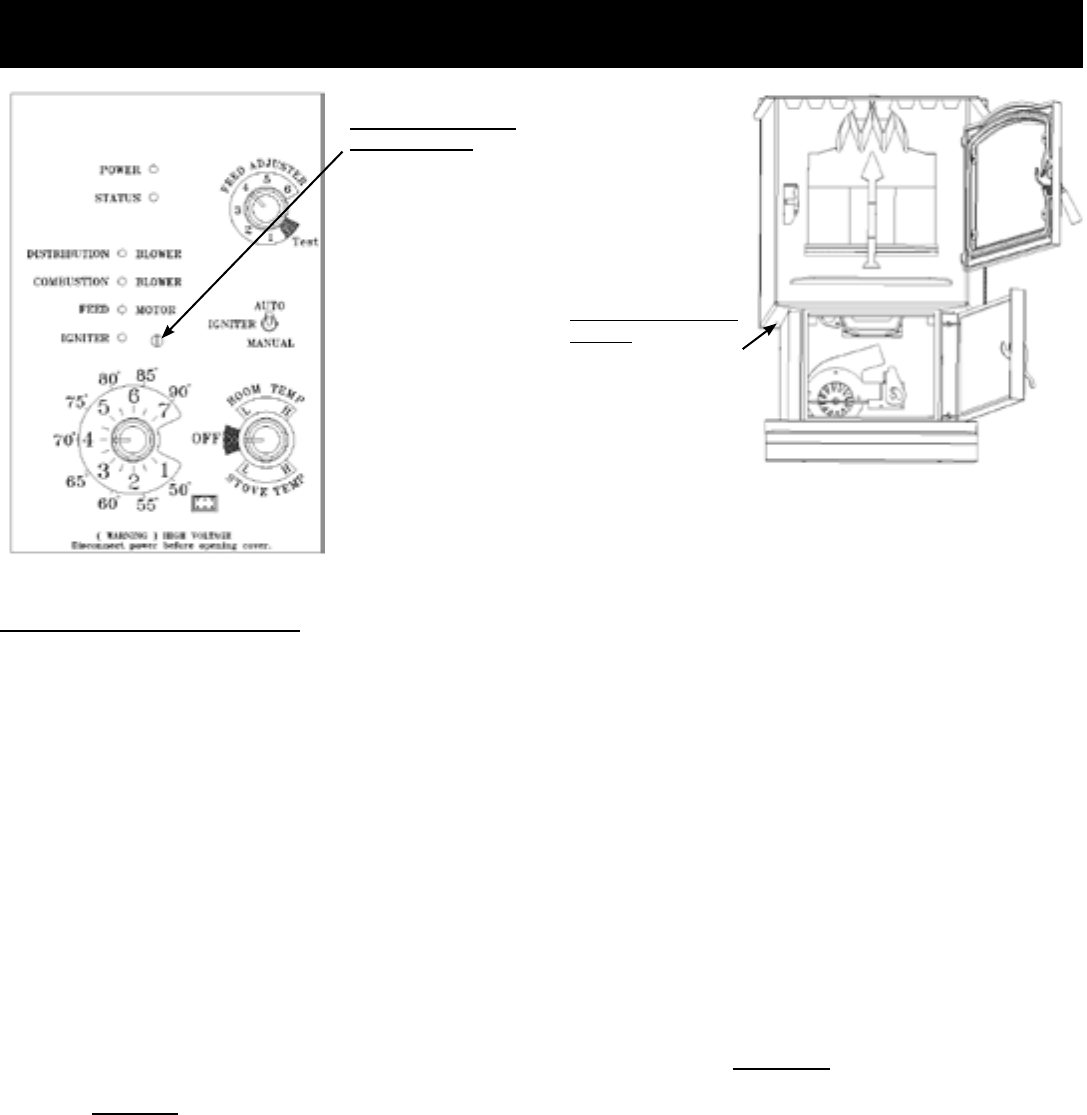
Low Draft Voltage Adjustment
Theseunitsarepre-testedatthefactorywithexactly120VAC,
60Hz.Theyarecheckedandadjustedforreboxtightness,
gasketleakage,motoroperationandigniteroperation.The
P61Aisthenfactorysetatamid-pointadjustmentandinmost
caseswillnotneedanyadjustments.NOTE: The factory low
draft setting may not be correct for the unit's permanent
installation conditions.
ThecontrolboardontheP61Aisequippedwithalowdraft
adjustmentport.Locatedonthecontrolfacejusttotheright
oftheigniterlight.Thisvoltageadjustmentisprovidedtoallow
theunittobeadjustedforthehouseholdvoltagewherethe
unitisgoingtobeinpermanentoperation.NOTE: The line
voltage varies from area to area and often home to home.
Thelowdraftvoltageshouldbeadjustedtoachievethemost
efcient burn on low burn or "maintenance". This voltage
adjustment allows the installer to change the low voltage
set point approximately 10 volts. This adjustment should
bedonebytheinstallerduringsetupbecauseadraftmeter
readingisrequired toinsurepropersetup.
Iftheunitisnotadjustedproperly,itdoesnotcauseasafety
concern.Iftheunitisadjustedtoohigh,onlyefciencyislost.
Iftheunitisadjustedtoolow,thelowdraftpressureswitch
willnotallowthefeedmotorortheignitertooperate.
Combustion Motor
Speed Control
Low draft only set
point.
The small straight
screwdriver slot is
plastic; therefore, the
unit can be adjusted
while in operation.
Fig.22
Fig. 23
Draft Meter bolt hole
location
The draft test hole is under
the left rear corner of the
rebox.
Low Draft Voltage Adjustment
Asimpledrafttestshouldbeperformedaftercompletingthe
uepipeinstallation.Torecordtheresultsforfuturereference:
1. Plugunitintoa120VAC,60Hzoutlet.
2. Closethehopperlid,frontviewdoor,andtheashpan.
Neitherpelletsorarearerequiredforthistest.
3. Withthemodeselectorinthe"OFF"position,turnthefeed
adjusterto"TEST".
4. Recordthehighdraft_____inW.C.(Normalis-.50to-.60)
ThecontrolwillbeontheHighDraftforatotalof1minute.
5. Aftertheminute,thecombustionmotorwillgodownto
lowdraftandthedistributionblowerwillgoonhigh.Allow
approximately 15 seconds to pass for the combustion
motortoslowbeforecheckingthelowdraft.
6. Ifthelowdraftisbetween-.35and-.45,recordthereading
_____inW.C. Ifthe readingishigher, slowlyturnthe
setscrewcounter-clockwiseuntilthedraftlowers.Ifthe
readingislower,veryslowlyturnthesetscrewclockwise
untilthedraftincreases.
NOTE: In some cases, the draft may not go as low as
-.35 to -.45 even with the set screw completely counter-
clockwise. Ideally, you should just set it as low as
possible.
21 P61A Pellet Stove 3-90-05822R29_10/13
Maintenance
Minimizing Creosote:
Wheneverwoodisburnedslowly,thepotentialexistsforcreosotetoformintheventing.Thechimneyorventingsystem
shouldbeinspectedperiodicallythroughouttheheatingseasontodetermineifacreosotebuilduphasoccurred.Ifasignicant
layerofcreosotehasaccumulated(3mmormore),itshouldberemovedtoreducetheriskofachimneyre.Aprofessional
chimneysweepisrecommended,sincetheywouldnormallyhavethecorrectequipmenttoensurepropercreosoteremoval.
If you experience a re in the venting system,turnthestoveto"OFF"toallowtheunittoshutdown.Calltheredepartment,
andbesureeveryoneisoutoftheresidence.Beforere-usingtheappliance,haveit,andtheventingsystemthoroughly
inspectedandreplaceanydamagedcomponents.
The glass in your Harman stove is a special 5mm
ceramicglass.
• Do not abuse the glass by striking or slamming
thedoor.
• Never burn the appliance if the door glass is
crackedorbroken.
• Replace only with Harman supplied glass. Do
NOTUseSubstitutes.
Soot and/or y-ash may accumulate on the viewing
glass,andwillocassionallyneedtobecleaned.Clean
theglasswithasoftclothandmildglasscleaner.Do
not clean the glass when hot, and avoid the use of
abrasivecleaners.
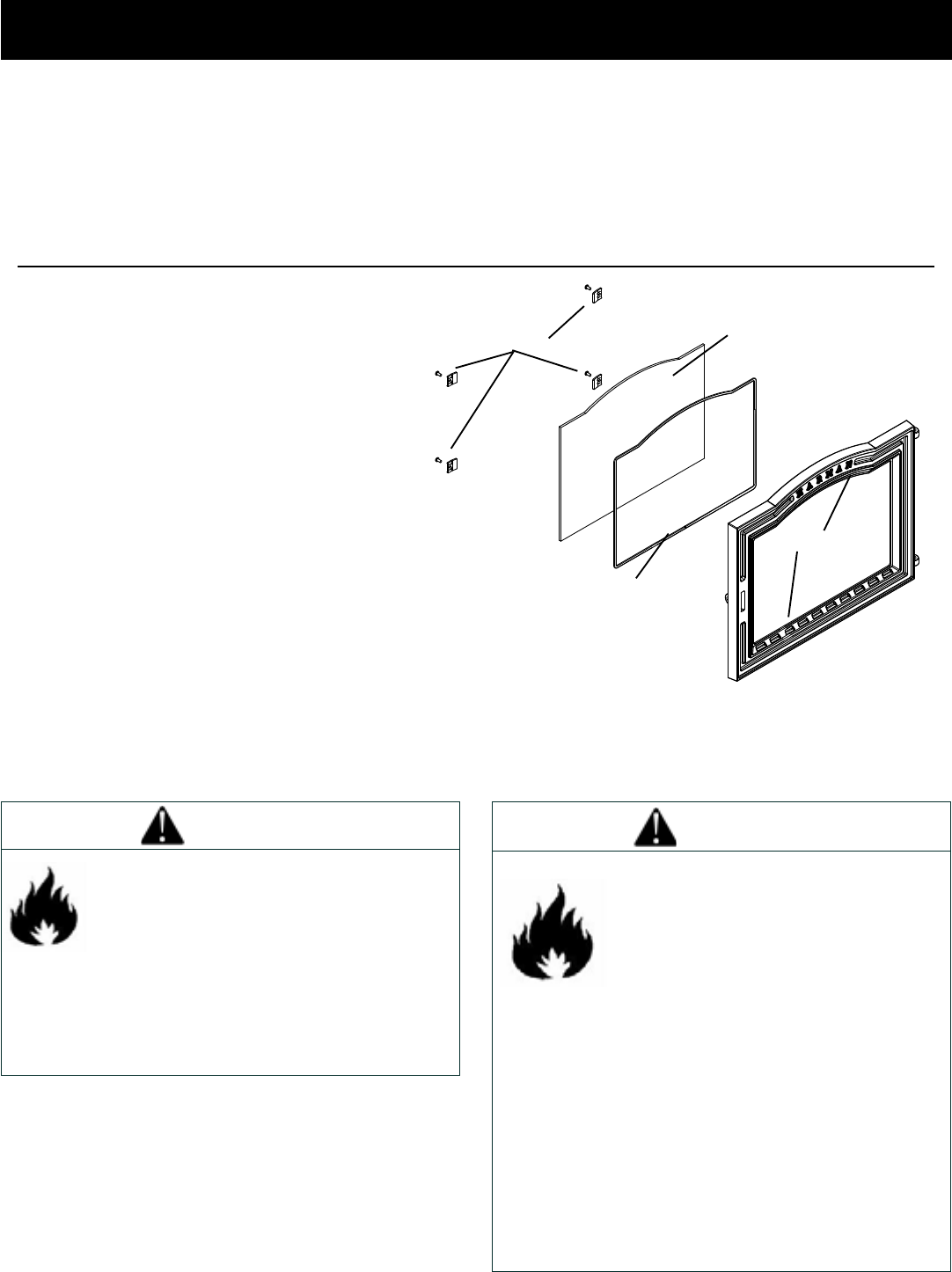
Glassreplacement
Carefully remove all remaining glass and gasket
materialspriortoreplacingtheglass.
Laythedoorfacedownonaatsurface.Removethe
glassretainersandscrews.Applythegasketmaterial
to the face of the new glass. Lay the glass into the
door,making surethat theglass is contained within
thechannelsandraisedareasofthedooritself.Lay
theglassretainersintopositionandinstallthescrews.Tighteneachscrewevenlytoavoidmakinganystresspoints.
Retainersandscrews Glass
Adhesivegasket
DoorFrame
WARNING
INSPECT APPLIANCE AND COMPONENTS
FOR DAMAGE. DAMAGED PARTS MAY
IMPAIR SAFE OPERATION.
• DO NOT INSTALL DAMAGED
COMPONENTS.
• DO NOT INSTALL INCOMPLETE
COMPONENTS.
• DO NOT INSTALL SUBSTITUTE
COMPONENTS.
REPORT DAMAGED PARTS TO DEALER.
FIRE RISK.
HEARTH & HOME TECHNOLOGIES
DISCLAIMS ANY RESPONSIBILITY
FOR, AND THE WARRANTY WILL
BE VOIDED BY, THE FOLLOWING
ACTIONS:
• INSTALLATION AND USE OF ANY DAMAGED
APPLIANCE.
• MODIFICATION OF THE APPLIANCE.
• INSTALLATION OTHER THAN AS INSTRUCTED BY
HEARTH & HOME TECHNOLOGIES.
• INSTALLATION OF PARTS OR COMPONENTS NOT
SUPPLIED OR APPROVED BY HEARTH & HOME
TECHNOLOGIES.
• OPERATING APPLIANCE WITHOUT FULLY
ASSEMBLING ALL COMPONENTS.
OR ANY SUCH ACTION THAT MAY CAUSE A FIRE
HAZARD.
WARNING
22P61A Pellet Stove
3-90-05822R29_10/13
Scraping the burn pot:
Whenever adding fuel to the hopper, take the time and
scrapethegratesurfaceoftheburnpot,usingthescrapertool
provided.Thiscanbedonewhileareisburning.Wearing
heat resistant gloves, open the rebox door. Scrape any
accumulatedashesfrominfrontofthere,intotheashpan.
Now,scrapeunderthere,inadownwarddirection,toloosen
anycarbondeposits.Donotscrapethereoutofthepot.
Whateveryouloosenwillbepushedoutwiththeowofnew
fuelintothepot.(Fig.33)
Ash Removal
Duetopotentialhightemperatures,itisrecommendedthat
the stove be out and cool prior to removing the ash pan.
Openthefrontdoorandgrasptheashpanbythehandle.
With the ash pan removed, swing the handle upward for
carrying.
Disposal of Ashes- Ashes should be placed in a steel
container with a tight tting lid. The closed container
of ashes should be moved outdoors immediately and
placed on a noncombustible oor or on the ground,
well away from all combustible materials, pending nal
disposal. If the ashes are disposed of by burial in soil
or otherwise locally dispersed, they should be retained
in the closed container until all cinders have been
thoroughly cooled. Other waste shall not be placed in
this container.
Cleaning:
Thestoveshouldbeshut-downandthoroughlycleanedafter
eachton ofpellets consumed.The cleanerthe stove, the
moreefcientitwillbe.
Note: Fuel with higher ash and/or moisture content will
requiremorefrequentcleanings.
1. Shut down the stove and disconnect power cord to
insurethatallmotorsarestopped.
2.Cleanheatexchangerwithscraperasshowning27.
3.Brushorscrapetheinsideofthestovetoremoveyash.
4.Scrapeburnpotwithatendofscraperprovidedwiththe
stove.Inspecttheholesontheburnpotsurface.SeeFig.
33.
5.Openburnpotclean-out.Cleanyashfromburnpotand
replacecover.
Maintenance
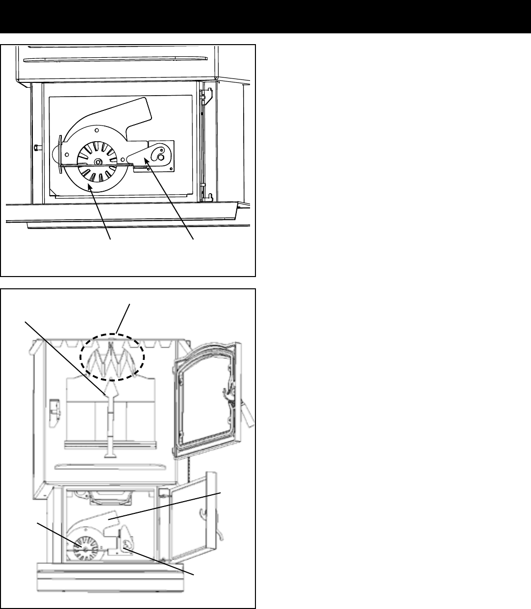
Combustion
Blower Cover
Blower Cover
Latch
Fig 26
Scraper
Blower
Cover Latch
Blower
Wheel
Flue
Outlet
Heat Exchanger Fins
Fig 27
23 P61A Pellet Stove 3-90-05822R29_10/13
Exposed blower wheel and
ue opening, NOTE: ESP
probe is visible.
ESP
Probe
Fig. 30
Fig. 31
Fig. 33
Maintenance
Burn pot
Clean-out
plate
Latch "open "with blower
cover partly removed. Burn
pot clean-out is open.
Latch "closed "with blower
cover in place. Burn pot
clean-out is closed.
Blower cover
removed.
Fig. 29Fig. 28
ESP
Probe
6.Removetheashpanandproperlydisposeoftheashes.
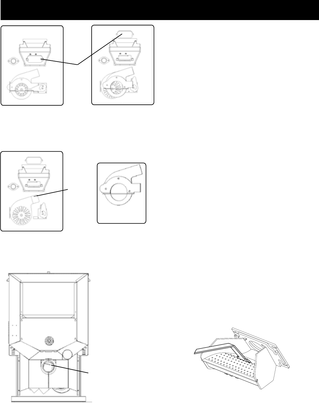
7.Removecombustionblowercoverbyturningtheblower
coverlatchvertical,seeFig.26.Slidingthecoveroutof
theslotontheleft.Thiswillexposethecombustionblower
wheelandueoutlet,Fig.27.
8.Cleanthecombustionblowerwheelwithabrushanda
vacuumcleaner.Note:Donotuseahouseholdvacuum
tocleanthestove.Werecommendthatyouuseashop
vacuumthat isequipped witha nedust ltercalled a
HEPA lteror avacuum specially madefor ashesand
soot.Using a vacuum which is not equipped with a
ne dust lter may clog and disperse y ash and soot
into the room.
NOTE: THE STOVE MUST BE COMPLETELY OUT
BEFORE YOU VACUUM THE STOVE. LIVE PELLETS, IF
SUCKED INTO THE VACUUM WILL LIGHT THE VACUUM
ON FIRE AND MAY ULTIMATELY CAUSE A HOUSE FIRE.
9.Useabrushtocleantheue,beingcarefulnottodamage
theESPprobe,seeFig.30.Theuegoesstraightthrough
intotheventpipe(Fig.27)therefore,theventpipecanalso
becleaned,tosomeextent,throughtheueoutlet.
10. Reinstalltheblowercoverandclosethelatch.
11. Slidetheashpanintostoveandlatchthedoor.
Soot and Fly Ash
Formation and Need for Removal - The products of
combustionwillcontainsmallparticlesofyash.Theyash
will collect in the exhaust venting system and restrict the
ow of the ue gases. Incomplete combustion, such as
occursduring startup, shutdown, or incorrect operation of
theroomheaterwillleadtosomesootformationwhichwill
collectintheexhaustventingsystem.The exhaust venting
system should be inspected at least once every year to
determine if cleaning is necessary.
Removingyashandsootimprovesefciencyandinsures
thattheueventingpassagewayisclearandunobstructed.
Thestoveshouldbecleanedaftereachtonofpellets(50
bags)andtheventingsysteminspectedandcleanedafter
eachheatingseason.
Be careful not to
damage ESP probe
when cleaning with
brush.
24P61A Pellet Stove
3-90-05822R29_10/13
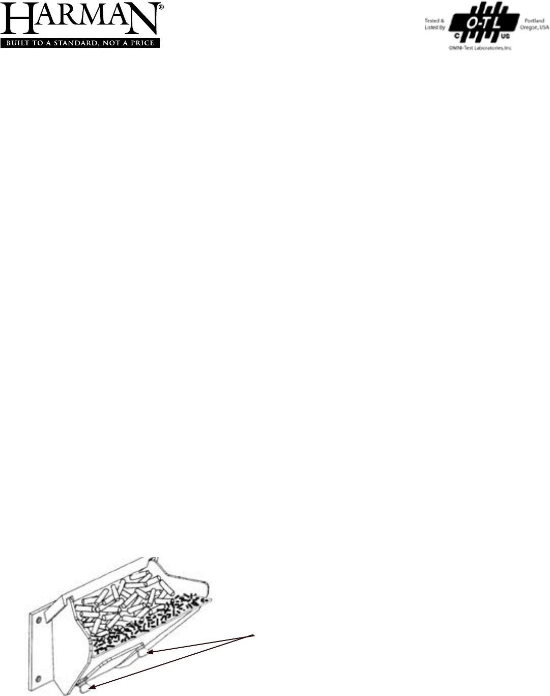
Burn Pot Cleaning and Maintenance
1. Scrapethetopholedsurfaceandsidesoftheburnpot.(Fig
33)Itisnotnecessarytocompletelyremoveallmaterial
fromtheburnpot.Theexcesswillbepushedoutduring
thenextuse.
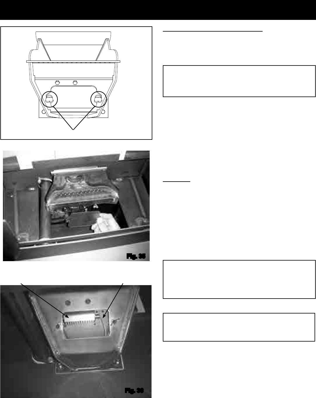
2. Loosenthe(2)wingthumbscrewsonthelowerfrontangle
oftheburnpot.(Fig.34)
3. Liftoffthe clean-outcover (Fig.35)toopen thebottom
clean-outchamber.(Fig.36)
4. Cleanashbuildupfrominsidethechamberwhilecover
isoff.Usethescrapertotaponthetopfrontedgeofthe
burn pot. This will help knock pieces of ash, loosened
bythescrapingprocess,downthroughtheholes.Italso
helpsknockscaleoffoftheigniterelement.
Figure 36
Theigniterismadetoberemovableforservicebyinsulated
male/femalewireconnectors.Theseconnectionsbetween
thehotleads(thewiresinsidetheburnpot)andthecoldleads
(thewiresfromthecontrolboard)arealwayspulledtothe
rearofthefeederbody. (Not coiled inside the burn pot.)
Itisveryimportantthattheseconnectionsaretotheinside
rearofthefeederbody.Also,theextrawireoftheigniterwire
serviceloopmustbepulledoutthroughtherearofthefeeder
andtiedupsothatitwillnotbedamagedbyanymovingparts.
DANGER
Disconnect electrical power to the unit before
removing cover.
Note: The hot lead/cold lead connection must always
be pulled to the rear of the feeder body before
operation.
Maintenance - Burn Pot
Fig. 34
Loosen wing screws
Fig. 35
Fig. 36
Burn pot igniter
Igniter hot lead wires
(high temperature)
Viewed from below through the ash pan opening.
WARNING
Use caution when cleaning burn pot clean-out
chamber. Do not damage the high temperature igniter
wires.
25 P61A Pellet Stove 3-90-05822R29_10/13
Maintenance - Cleaning the Feeder Body
Safety Features
Thelowdraftsensorwhichisavacuumdifferentialswitch,monitorsthenegativepressure(draft)inthereboxthrougha
portontherearofthefeeder.Poordraftwillresultinaninterruptionofpowertothefeedermotor.Poordraftcanbecaused
byblockageintheexhaust,excessivebuild-uponthecombustionblowerfanblades,afailedcombustionblower,oradoor
orotheropeningtothereboxnotsealedproperly.Thecircuitboardismonitoringthepositionofthisswitch.Duringafeed
cycle,ifthisswitchweretoopen,thefeedmotorlightonthecontrolwillstayilluminatedwiththepowerbeinginterrupted
bytheswitch.Iftheswitchopenswhenthecycleisatrest,thepowerlightforthefeedmotorwillnotilluminate.Besureall
doors,includingthehopperlid,aresecurelyclosedwhenoperatingtheappliance.
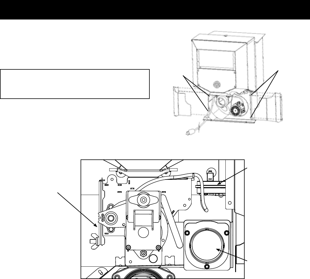
Pellet Fines
may build up
in this area
Low
Draft
Sensor
Air
Intake
Flapper
Pelletnesmayaccumulateinthefeederbodyoveraperiod
oftime;therefore,ayearlyinspectionandcleaningofthis
areamustbeperformed.
Tocleanoutnes:
1. Removetherearcoverpanels.
DANGER
Disconnect electrical power to the unit before
removing cover.
5/16" Hex Head
Screws (2 on
each side)
5/16" Hex Head
Screws (2 on
each side)
2. Remove wing nut and feeder cover on the side of the
feeder.
3. Useavacuumcleanertoremoveallnes.
4. Reinstallfeedcover,wingnut,andrearcoverpanels.

26P61A Pellet Stove
3-90-05822R29_10/13
SMOKE IS VISIBLE COMING OUT OF VENT
1.Air-fuelratioistoorich.
a.Feedratetoohigh.
b.Drafttoolowcausedbyagasketleak.
LOW HEAT OUTPUT
1.Feedratetoolow
2.Drafttoolowbecauseofgasketleak.
3.Poorqualityordamppellets
4.Combinationof1and2.
Trouble-Shooting
Helpful Hints
Cleaning Burn Pot
Wheneveryourstoveisnotburning,taketheopportunityto
scrapethe burn pot to removecarbon buildup.A vacuum
cleanerishandytoremovetheresidue.Be sure the stove
is cold if you use a vacuum.
Carbonbuildupcanbescrapedloosewiththereburning
usingthespecialtoolprovidedwithyourstove.Scrapethe
oorandsidesoftheburnpot.Thecarbonwillbepushedout
bytheincomingfuel.Alwayswearglovestodothis.
Removing Ashes
TurntheTempDialtonumber1approximately30minutes
beforeremovingashes.Thiswillresultinacoolerstoveand
ashpan.
Curing Paint
Youmaynoticesomesmokeandodorduringtherstringof
theappliance.Thisislikelypartofthepaintcuringprocess,
andwilldiminishwithtime.Considerkeepingawindowopen
duringthersthourofoperation,toremoveanyassociated
odors.
Keep the stove free of dust and dirt, especially around
the motors and circuit board.
STOVE DOES NOT FEED
1. Nofuelinhopper.
2. Fireboxdraftmaybetoolowforsensingswitchinfeeder
circuittooperate.Check for closed doors,looseor
missinggasketondoorsorhopperlid.
3. FeedmotorwillnotrununtiltheESPcontrolsensesa
certaintemperature.Maybeyoudidnotputenoughfuel
orstartinggelintheburnpotbeforemanuallylighting
there.
4.Restrictioninthehopperorfeeder.Removeallfueland
examine.Cleartheobstruction.
5. Feedmotorhasfailed.
PARTIALLY BURNED PELLETS
1. Feedratetoohigh.
2. Poorairtofuelmixture.(Checkburnpotclean-outcover
andairintake).
3. Burn pot or heat exchanger tubes may need to be
cleaned.
4. Combinationofalltheabove.
5. #6 status blink:A6blinkcontrolboardstatusindication
iscausedbypoororincompletecombustion.Thecircuit
boardhastheabilitytotrackthecombustionthrough
feedsettingsandESPtemperatures.Whenthecontrol
boardhascalculatedpoororincompletecombustion,
itwillshutdowntheunitasasafetyfeature.(Pooror
incomplete combustion is a contributor of creosote
whichmaycauseachimneyre)
A 6 blink status may be caused by several things:
1. Blockedorpartiallyblockedue.
2. Blockedorpartiallyblockedinletair.
a. Backdraft damper on the inlet pipe may be stuck
closed.
b. If outside air is installed, the inlet cover may be
blocked.
3. Theairchamberundertheburnpotmaybelledwith
nesandsmallbitsofash.
4. Theholesintheburnpotmaybegettinglledwithash
orcarbonbuildup.
5. Combustionblowerfanbladesmayneedcleaned.
6. Fuelrestrictionsasnotedabove.
SMOKE SMELL
Sealtheventpipejointsandconnectiontostovewithsilicone.
Theexhaustventistheonlypartofthesystemthatisunder
positivepressure.
FIRE HAS GONE OUT- Check for status light.
1.Nofuelinhopper.
2.Draftistoolow,blockedue.
3.Somethingisrestrictingfuelow.
4.Hopperlidnotclosedproperly.
5.Feedmotororcombustionblowerhasfailed.
Fuel
Pelletfuelsareputinto3categoriesintermsofashcontent.
Premiumat1%orless,Standardat3%orlessandallothers
at3%ormore.
TheP61Aiscapableofburningall3categoriesofpellets,
anduptoa50%mixturewithshelledcorn,seenextpage
forspecialinstructions.
Itshouldbenoted,thathigherashcontentwillrequiremore
frequent ash removal, scraping of the burn pot, and may
providelessBTU'sperpound.
Themoisturecontentofpelletsmustnotexceed8%,corn
15%. Higher moisture will rob BTU's and may not burn
properly.
Fuelshouldbestoredinadryarea,outsideofthestove's
installationclearanceareaandoutsideofthespacerequired
forchargingandashremoval.SeePage7.

27 P61A Pellet Stove 3-90-05822R29_10/13
Fuel Specications
Fuel and Fuel Storage
Pellet fuel quality can uctuate from manufacturer to
manufacturer,andevenfrombagtobag.
Hearth & Home Technologies recommends using only
fuelthatiscertiedbythePelletFuelsInstitute(PFI).
FuelMaterial
• Madefromsawdustand/orotherwoodby-products
• Shelledeldcorn(whenmixedwithwoodpellets)
• Sourcematerialtypicallydeterminesashcontent
HigherAshContentMaterial
• Hardwoodswithhighmineralcontent
• Barkandleavesassourcematerial
• "Standard"gradepellets,cornandotherbiomass
LowerAshContentMaterial
• Softwood;pine,r,etc.
• Materialswithlowermineralcontent
• "Premium"gradepellets
Shelledeldcorn
• Mustbe15%moisturecontentorless
• Mustbecleanandfreeofdebris
• Mustbemixedwithwoodpellets.(Upto50%)
• Stalkparts,excessivenesandcobremnantsmay
causefeedsystemjamsorblockage
CAUTION! Do not burn fuel that contains an additive;
(such as soybean oil)
• Maycausehopperre
• Damagetoproductmayresult
Readthelistofingredientsonthepackaging.Ifyouare
buyingeldcorn,theonlyingredientlistedshouldbeeld
corn.
WARNING! Risk of Chemical Poisoning!
DoNOTburntreatedseedcorn
• Chemicalpesticidesareharmfulorfatalifswallowed
• Burning treated seed corn will void the product
warranty
Clinkers
Mineralsandothernon-combustiblematerials,likesand,
willturnintoahardglass-likesubstancewhenheated.
Trees from different areas will vary in mineral content.
For this reason, some fuels will produce more clinkers
thanothers.
Moisture
Always burn dry fuel. Burning fuel with high moisture
content takes energy to dry and tends to cool the
appliance thus, robbing heat from your home. Damp
pelletfuelcouldturnbackintosawdustwhichdoesnot
owproperlythroughthefeedsystem.
Size
• Pellets are either 1/4 inch or 5/16 inch (6-8mm) in
diameter
• Lengthshouldbenomorethan1-1/2inches(38mm)
• Pelletlengthcanvaryfromlottolotfromthesame
manufacturer
Performance
• Higher ash content requires more frequent
maintenance.
• "Premium" grade pellets will produce the highest
heatoutput.
• Burningpelletslongerthan1-1/2inches(38mm)can
causeinconsistentfeedingand/orignition.
We recommend that you buy fuel in multi-ton lots
wheneverpossible. However,we dorecommendtrying
different brands prior to purchasing multi-ton lots, to
ensureyoursatisfaction.
CAUTION! Attempting to burn fuels such as charcoal
has the potential of generating Carbon Monoxide which
is DEADLY. Never burn fuels other than those listed on
the appliance safety label.
Whenchangingfromwoodpelletstoacorn/pelletmixture,
theFEEDADJUSTERwilllikelyneedadjustedtoalower
setting.Whenundermaximumdemand,ensurethereis
nounburnedfuelbeingpushedintotheashpan.
Storage
• Wood pellets should be left in their original sealed
baguntilreadytouse,topreventmoisture.
• Shelled corn should be stored in a tightly sealed
containertopreventmoistureandtodeterpests
• Donotstorefuelwithinthespeciedclearanceareas,
orinalocationthatwillinterferewithroutinecleaning
andmaintenanceprocedures.
CAUTION
Testedandapprovedforusewithwoodpelletsanda
mixtureofshelledeldcornandwoodpelletsONLY.
Burningofanyotherfuelwillvoidyourwarranty.
NOTICE
Hearth&HomeTechnologiesisnotresponsiblefor
stove performance or extra maintenance required
asa resultofusingfuel withhigherashor mineral
content.
3-90-05822R29_10/13
Harman pellet burning, free-standing stoves and inserts have been tested to ASTM E1509 for burning shelled corn
in a mixture with wood pellets. The listing approves up to a 50% corn and 50% pellet mixture. Dierent mixtures of
corn will have distinctively dierent burn characteristics depending upon moisture content and variety. The operator
should closely monitor the stove’s operation when burning a new corn/pellet mixture or a dierent variety of corn,
and make any necessary adjustments to feed rate. Since corn is typically higher in ash and moisture content, cleaning
and ash removal will be needed more frequently.
Operation in Stove Temp mode
Set feed adjuster to # 3. Set temperature knob to #3, Turn mode selector knob onto “Stove Temp” mode. After the re
has lit, watch that the fuel does not feed too fast that it pushes the red glowing fuel bed o of the burn pot grate. If it
does, lower the feed adjuster setting or use a lower percentage of corn in the mixture. After the stove has burned for
10 minutes and the entire fuel bed is burning, the feed adjuster and temperature knobs may be adjusted for higher
heat output if desired. Maximum feed has been reached when the re bed is about ½ to 1 inch from the end of the
burn pot. Settings will vary with dierent types, moisture levels and mix ratios of corn. If you are having diculty burn-
ing a 50% corn / 50% wood pellet mixture, try a lower percentage of corn.
Operation in Room Temp mode
Set feed adjuster to # 2 or # 3. Set temperature knob to desired amount. Turn mode selector knob onto “Room Temp”
mode. After the re has lit, watch that the fuel does not feed too fast that it pushes the red glowing fuel bed o of the
burn pot grate. After the stove has burned for 10 minutes and the entire fuel bed is burning, the feed adjuster may be
set to a higher output level if desired. Maximum feed has been reached when the re bed is about ½ to 1 inch from
the end of the burn pot. It is recommended that after burning at the desired settings, turn the stove o and allow it to
cool, then turn it back on in “Room Temp” mode and watch the stove restart and verify correct operation. Settings will
vary with dierent types, moisture levels and mix ratios of corn. If you are having diculty burning a 50% corn 50%
wood pellet mixture, try a lower percentage of corn.
Changes to Maintenance Schedule
Wood pellets average around 6% moisture content or less. Corn will be 14 or 15% moisture. With more moisture in
the fuel, more maintenance will be incurred. Burn pot scraping may need to be done once per day. The ash pan will ll
more quickly and may need emptied weekly. Most importantly, remove the burn pot cleanout cover weekly to clean
the air passage and the igniter element. Excessive buildup on the igniter may lead to shortened igniter life.
Venting Consideration: Check with your venting manufacturer regarding possible exclusions when a mixture of corn
and pellets is burned.
Addendum for Burning Corn and Pellet Fuel Mixture
Loosen these two wing screws for access
to clean the air passage and igniter.
* For P38+ model, follow Stove Temp instructions. Keep feed rate on #3 or
above when using a wall thermostat.

3-90-05822R29_10/13
29 P61APelletStove
Addendum
Minimizing Smoke During Loss of Power Using Battery Back-up
Harman® strongly recommends installing battery back-up to minimize entry of smoke into the
room in the event of power loss.
Your pellet/biomass burning appliance relies on a combustion blower to remove exhaust. A power failure
will cause the combustion blower to stop. This may lead to exhaust seeping into the room. Vertical rise
in the venting may provide natural draft. It is, however, no guarantee against leakage.
There are two Harman® approved battery back-up options for your appliance:
Uninterruptible Power Supply (UPS) UPS battery back-ups are available online or at computer and
ofce equipment stores. Your Harman® appliance with Rev E or later software available beginning in
November 2010 may be plugged directly into a Harman® approved UPS:
• The APC (American Power Conversion) model #BE750G and the TrippLite model
INTERNET750U are tested and approved. Other brands or models may not be compatible.
When power is lost, a fully charged UPS will power a safe, combustion blower only shut-down. Your
appliance will pulse the blower every few seconds to clear exhaust until the re is out. NOTE: The UPS
provides safe shut-down only. It is not intended for continued operation.
Your appliance will recognize when power is restored. What happens depends on ESP temperature
and whether it is equipped with automatic ignition:
• In “Automatic” setting, units equipped with automatic ignition will respond to the set point
and ESP temperature and resume normal operation.
• In “Manual” setting or for units without automatic ignition:
• If the ESP is cool, the appliance will remain shut down.
• If the re is out and the ESP is still warm, the feeder may restart. Since the re is out, the
ESP temperature will not rise. The unit will then shut-down, and may ash a six-blink status
error. (See ESP error codes)
• If the re is still burning, it will resume normal operation.
Contact your dealer if you have questions about UPS compatibility with your appliance.
Harman® Surere 512H Battery Back-up The 512H connects to a 12 volt deep cycle battery that will
run your appliance for up to eight (8) hours. It includes a trickle charge feature that keeps your battery
charged when power is available. NOTE: If the power is out for longer than battery life, smoke
leakage may still occur unless your stove has been safely shut down.
CAUTION! Always keep appliance doors and hopper lid closed and latched during operation
and during power failures to minimize risk of smoke or burn-back.
CAUTION! Use only Harman® approved battery back-up devices. Other products may not
operate properly, can create unsafe conditions or damage your appliance.
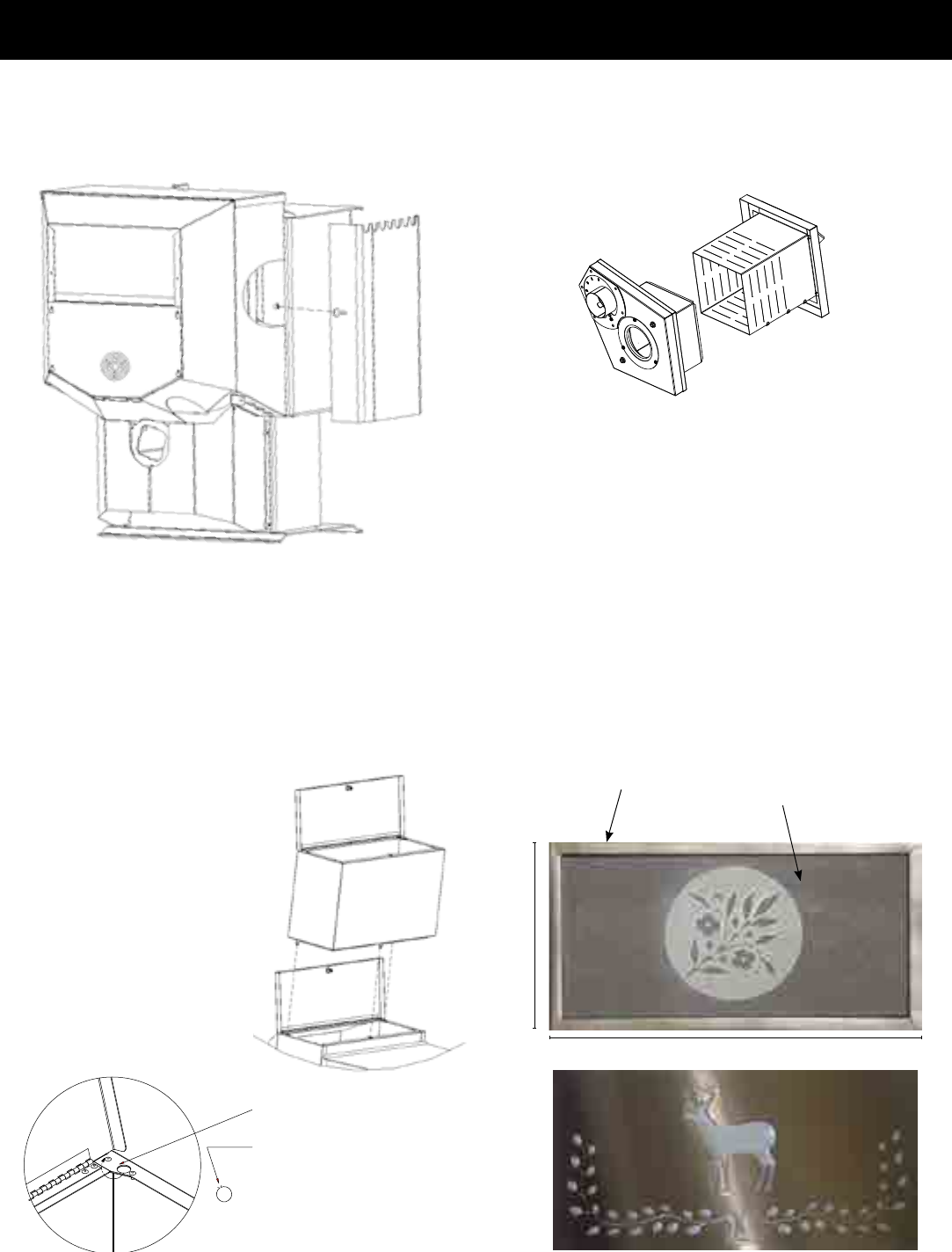
30P61A Pellet Stove
3-90-05822R29_10/13
On the rear of the stove hopper there is a
hole to fasten the hopper extension into place.
On some units, this hole will need to be
opened. You will notice a small uncut area on
rear of the knockout. Push downward with a
screwdriver or like tool until the knockout is
rotated as far back to the inside of the hopper
as possible. This will allow the swell latch of the
hopper extension to fully expand to the bottom
side of the hole for a proper seal.
Options
Side Heat Shields
Sideheatshieldsareavailabletoreducetheclearanceto
combustiblematerials.
Part#1-00-08631
Hopper Extension -Part#1-00-08636
The hopper extension allows you to put more pellet fuel
inthehopperwhichextendstheburntimeononeloadof
pellets.Thehopperextensionadds70poundstotheexisting
hoppercapacity,allowingyoutoload140poundsofpellets
atonetime.Theextensionsealstotheunithopperwiththree
latches.Somemodelswillrequireaknockoutberemoved
fromtheunithopperpriortoinstallingtheextension.
Decorative Slate Options
The decorative slate tiles measure 11.938" x 5.938". The
tile/slateframeisnotnecessarytoholdthetileinplaceon
thestove.Thereare4decorativeslatechoices.Seedealer
forsamples.
TheBrushedStainlessdeercutout,picturedbelow,isanother
optionavailable.Thiscutoutrevealsthecolorofthestove
throughthecutoutshapes.
5.938"
11.938"
frame tile/slate
Direct Vent Wall Passthrough Kit
You may choose to use the optional Direct Vent Wall
Passthrough Kit (part #1-00-677177) which incorporates
ventingpassthroughandoutsideairintoonecomponent.
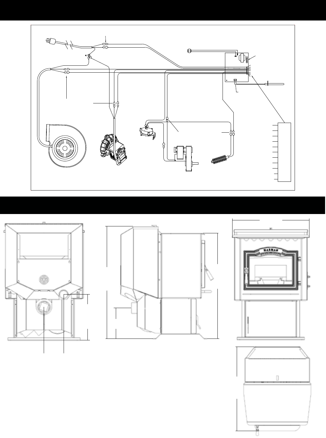
31 P61A Pellet Stove 3-90-05822R29_10/13
Wiring Diagram
Weight 249 lbs.
Blower 135 cfm
Feed Rate .75 to 7.5 lbs. per hr.
Hopper Capacity 72 lbs.
Fuel Wood Pellets- Corn/Pellet Mixture
Flue Size 3 inch
Outside Air Size 2 3/8" I.D.
Fuse Rating 5 amp
51/4"
291/2"
Specications
323/8"
341/2"
10"
123/8"
231/2"
CONTROL
BOARD
HARMAN P43/P61A/P68 PELLET STOVE WIRING DIAGRAM
IGNITER ELEMENT
INSIDE BURNPOT
18/3 RUBBER CORD
DISTRIBUTION BLOWER
CONTACTS
COMBUSTION MOTOR
LOW PRESSURE SWITCH
N.O.
LT.BLUE
LT.BLUE
MALE/FEMALE CONNECTIONS
18/3 RUBBER CORD
POWER CORD
GREEN WIRE IS GROUND
BONDED TO STOVE BODY
MALE/FEMALE CONNECTIONS
GREEN
GREEN
WHITE
WHITE
BLUE
RED
WHITE
WHITE
BROWN
REMOTE SENSOR PORTS
BLACK
YELLOW
RED 10
WHITE 11 PIN PLUG
PART NO. 3-89-06504
BLACK 11
BROWN
PLUGGED
YELLOW
EMPTY
BLUE
WHITE
WHITE
WHITE
WHITE
7
8
9
5
6
3
2
4
1
6 AMP GLASS FUSE
TWISTED WIRE
ESP
ESP
4
8
6
5
11
10
9
1
3
ESP PROBE
MAX WATTS - 516 @ 120VAC 60Hz = 4.3 A
STANDARD USE WATTS - 384 @ 120VAC 60Hz = 3.2 A
MALE/FEMALE CONNECTIONS
FEEDER AUGER MOTOR
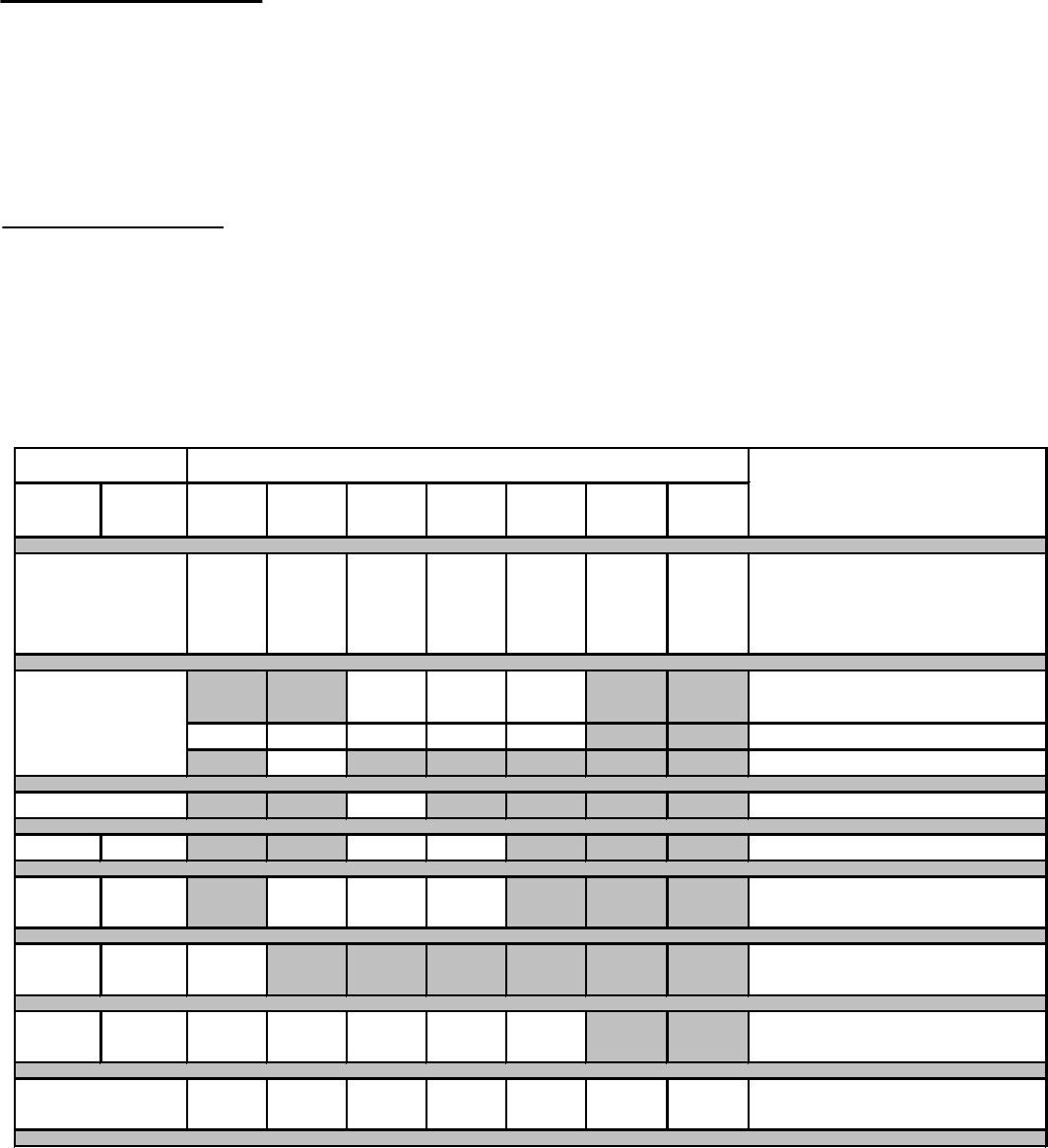
4021-645F02-18-13 Page1of2
Hearth & Home Technologies
LIMITED LIFETIME WARRANTY
Hearth&HomeTechnologies,onbehalfofitshearthbrands(”HHT”),extendsthefollowingwarrantyforHHT
gas,wood,pellet,coalandelectrichearthappliancesthatarepurchasedfromanHHTauthorizeddealer.
WARRANTY COVERAGE:
HHTwarrantstotheoriginalowneroftheHHTapplianceatthesiteofinstallation,andtoanytransfereetakingownership
oftheapplianceatthesiteofinstallationwithintwoyearsfollowingthedateoforiginalpurchase,thattheHHTappliance
willbefreefromdefectsinmaterialsandworkmanshipatthetimeofmanufacture.Afterinstallation,ifcoveredcompo-
nentsmanufacturedbyHHTarefoundtobedefectiveinmaterialsorworkmanshipduringtheapplicablewarrantyperiod,
HHTwill,atitsoption,repairorreplacethecoveredcomponents.HHT,atitsowndiscretion,mayfullydischargeallofits
obligationsundersuchwarrantiesbyreplacingtheproductitselforrefundingtheverifiedpurchasepriceoftheproduct
itself.Themaximumamountrecoverableunderthiswarrantyislimitedtothepurchasepriceoftheproduct.Thiswarranty
issubjecttoconditions,exclusionsandlimitationsasdescribedbelow.
WARRANTY PERIOD:
Warrantycoveragebeginsonthedateoforiginalpurchase.Inthecaseofnewhomeconstruction,warrantycoverage
beginsonthedateoffirstoccupancyofthedwellingorsixmonthsafterthesaleoftheproductbyanindependent,
authorizedHHTdealer/distributor,whicheveroccursearlier.Thewarrantyshallcommencenolaterthan24months
followingthedateofproductshipmentfromHHT,regardlessoftheinstallationoroccupancydate.Thewarrantyperiodfor
partsandlaborforcoveredcomponentsisproducedinthefollowingtable.
Theterm“LimitedLifetime”inthetablebelowisdefinedas:20yearsfromthebeginningdateofwarrantycoveragefor
gasappliances,and10yearsfromthebeginningdateofwarrantycoverageforwood,pellet,andcoalappliances.These
timeperiodsreflecttheminimumexpectedusefullivesofthedesignatedcomponentsundernormaloperatingconditions.
Seeconditions,exclusions,andlimitationsonnextpage.
Parts Labor Gas Wood Pellet EPA
Wood
Coal Electric Venting
XXXXXXX
Allpartsandmaterialexceptas
coveredbyConditions,
Exclusions,andLimitations
listed
XXX
Igniters,electroniccomponents,
andglass
X X X X X Factory-installedblowers
X Moldedrefractorypanels
X Firepotsandburnpots
5years 1year X X Castingsandbaffles
7years 3years X X X Manifoldtubes,
HHTchimneyandtermination
10
years
1year X Burners,logsandrefractory
Limited
Lifetime
3years X X X X X Fireboxandheatexchanger
XXXXXXX Allreplacementparts
beyondwarrantyperiod
WarrantyPeriod HHTManufacturedAppliancesandVenting
1Year
ComponentsCovered
3years
2years
90Days

4021-645F02-18-13 Page2of2
WARRANTY CONDITIONS:
• ThiswarrantyonlycoversHHTappliancesthatarepurchasedthroughanHHTauthorizeddealerordistributor.Alistof
HHTauthorizeddealersisavailableontheHHTbrandedwebsites.
• ThiswarrantyisonlyvalidwhiletheHHTapplianceremainsatthesiteoforiginalinstallation.
•ThiswarrantyisonlyvalidinthecountryinwhichtheHHTauthorizeddealerordistributorthatsoldtheappliance
resides.
• Contactyourinstallingdealerforwarrantyservice.Iftheinstallingdealerisunabletoprovidenecessaryparts,contact
thenearestHHTauthorizeddealerorsupplier.Additionalservicefeesmayapplyifyouareseekingwarrantyservice
fromadealerotherthanthedealerfromwhomyouoriginallypurchasedtheproduct.
• Checkwithyourdealerinadvanceforanycoststoyouwhenarrangingawarrantycall.Travelandshippingcharges
forpartsarenotcoveredbythiswarranty.
This warranty is void if:
• Theappliancehasbeenover-firedoroperatedinatmospherescontaminatedbychlorine,fluorine,orotherdamaging
chemicals.Over-firingcanbeidentifiedby,butnotlimitedto,warpedplatesortubes,rustcoloredcastiron,bubbling,
crackinganddiscolorationofsteelorenamelfinishes.
• Theapplianceissubjectedtoprolongedperiodsofdampnessorcondensation.
• Thereisanydamagetotheapplianceorothercomponentsduetowaterorweatherdamagewhichistheresultof,but
notlimitedto,improperchimneyorventinginstallation.
LIMITATIONS OF LIABILITY:
• Theowner’sexclusiveremedyandHHT’ssoleobligationunderthiswarranty,underanyotherwarranty,expressor
implied,orincontract,tortorotherwise,shallbelimitedtoreplacement,repair,orrefund,asspecifiedabove.Inno
eventwillHHTbeliableforanyincidentalorconsequentialdamagescausedbydefectsintheappliance.Somestates
donotallowexclusionsorlimitationofincidentalorconsequentialdamages,sotheselimitationsmaynotapplytoyou.
Thiswarrantygivesyouspecificrights;youmayalsohaveotherrights,whichvaryfromstatetostate.EXCEPTTO
THEEXTENTPROVIDEDBYLAW,HHTMAKESNOEXPRESSWARRANTIESOTHERTHANTHEWARRANTY
SPECIFIEDHEREIN.THEDURATIONOFANYIMPLIEDWARRANTYISLIMITEDTODURATIONOFTHE
EXPRESSEDWARRANTYSPECIFIEDABOVE.
WARRANTY EXCLUSIONS:
Thiswarrantydoesnotcoverthefollowing:
• Changesinsurfacefinishesasaresultofnormaluse.Asaheatingappliance,somechangesincolorofinteriorand
exteriorsurfacefinishesmayoccur.Thisisnotaflawandisnotcoveredunderwarranty.
• Damagetoprinted,plated,orenameledsurfacescausedbyfingerprints,accidents,misuse,scratches,melteditems,
orotherexternalsourcesandresiduesleftontheplatedsurfacesfromtheuseofabrasivecleanersorpolishes.
• Repairorreplacementofpartsthataresubjecttonormalwearandtearduringthewarrantyperiod.Theseparts
include:paint,wood,pelletandcoalgaskets,firebricks,grates,flameguides,batteriesandthediscolorationofglass.
• Minorexpansion,contraction,ormovementofcertainpartscausingnoise.Theseconditionsarenormalandcom-
plaintsrelatedtothisnoisearenotcoveredbythiswarranty.
• Damagesresultingfrom:(1)failuretoinstall,operate,ormaintaintheapplianceinaccordancewiththeinstallation
instructions,operatinginstructions,andlistingagentidentificationlabelfurnishedwiththeappliance;(2)failureto
installtheapplianceinaccordancewithlocalbuildingcodes;(3)shippingorimproperhandling;(4)improperopera-
tion,abuse,misuse,continuedoperationwithdamaged,corrodedorfailedcomponents,accident,orimproperly/
incorrectlyperformedrepairs;(5)environmentalconditions,inadequateventilation,negativepressure,ordrafting
causedbytightlysealedconstructions,insufficientmake-upairsupply,orhandlingdevicessuchasexhaustfansor
forcedairfurnacesorothersuchcauses;(6)useoffuelsotherthanthosespecifiedintheoperatinginstructions;(7)
installationoruseofcomponentsnotsuppliedwiththeapplianceoranyothercomponentsnotexpresslyauthorized
andapprovedbyHHT;(8)modificationoftheappliancenotexpresslyauthorizedandapprovedbyHHTinwriting;
and/or(9)interruptionsorfluctuationsofelectricalpowersupplytotheappliance.
• Non-HHTventingcomponents,hearthcomponentsorotheraccessoriesusedinconjunctionwiththeappliance.
• Anypartofapre-existingfireplacesysteminwhichaninsertoradecorativegasapplianceisinstalled.
• HHT’sobligationunderthiswarrantydoesnotextendtotheappliance’scapabilitytoheatthedesiredspace.Informa-
tionisprovidedtoassisttheconsumerandthedealerinselectingtheproperappliancefortheapplication.Consider-
ationmustbegiventoappliancelocationandconfiguration,environmentalconditions,insulationandairtightnessof
thestructure.
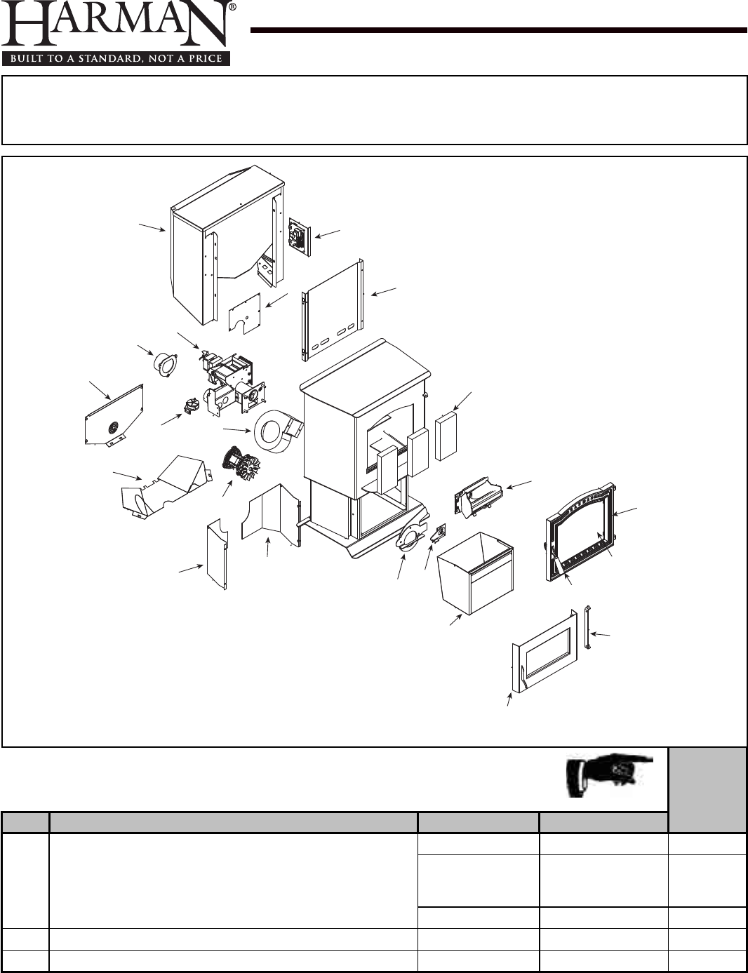
Service Parts P61A Pellet
Beginning Manufacturing Date: N/A
Ending Manufacturing Date: Active
IMPORTANT:THISISDATEDINFORMATION.Partsmustbeorderedfromadealerordistributor.
Hearth and Home Technologies does not sell directly to consumers.Providemodelnumber
andserialnumberwhenrequestingservicepartsfromyourdealerordistributor.
Stocked
at Depot
ITEM Description COMMENTS PART NUMBER
1 HopperAssembly
Pre008085092 1-10-08622 Y
008085092
Thru008087704
Orderbothparts
1-10-09685A
1-00-232108 Y
Post008087704 1-10-09685A Y
HopperSwitch48" Post008087704 3-20-232108 Y
RetrotHopperSwitchKitforExtension 1-00-06826 Y
Additionalservicepartsonfollowingpage. 10/13
1-90-05801-2 (Charcoal) (June 2011)
1-90-05801-3 (Golden re) (June 2011)
1-90-05801-4 (Metallic Blue) (Jan 2010)
124
2 & 3
4
5
8
6
7
9
10 11
12 13
16
15
14
17
18
19
20
21
22
23
Steel Pellet Stove
1-90-05801-1 (Black)
1-90-05801-5 (Honey Glo) (June 2009)
1-90-05801-10 (Mojave Red) (Jan 2010)
1-90-05801-12 (Forest Green) (Jan 2010)
Retired Units
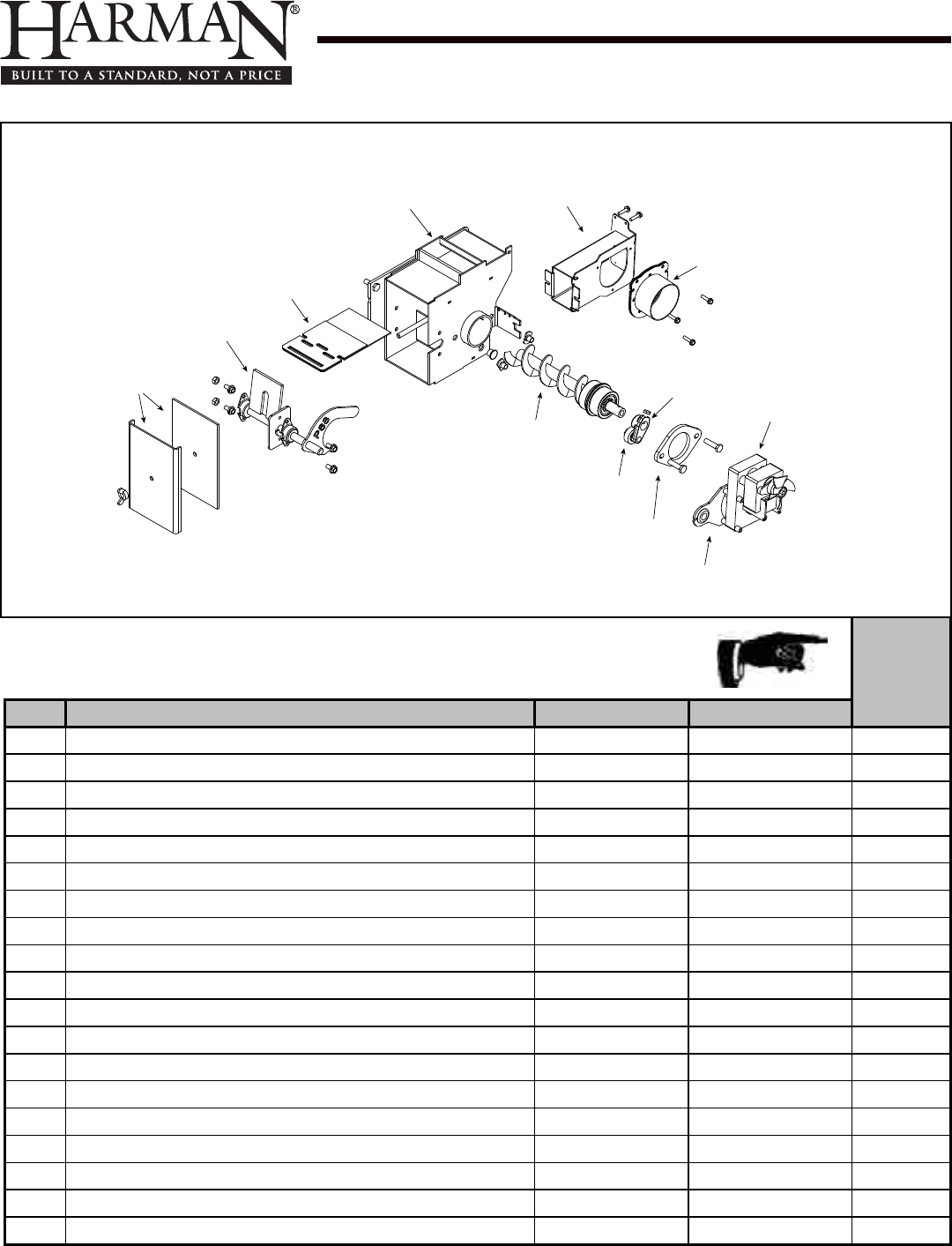
Service Parts P61A Pellet
Beginning Manufacturing Date: N/A
Ending Manufacturing Date: Active
IMPORTANT:THISISDATEDINFORMATION.Partsmustbeorderedfromadealerordistributor.
Hearth and Home Technologies does not sell directly to consumers.Providemodelnumber
andserialnumberwhenrequestingservicepartsfromyourdealerordistributor.
Stocked
at Depot
ITEM Description COMMENTS PART NUMBER
2 FeederAssembly Pre008085092 1-10-09674A
2.1 AirIntakeDamperAssembly 1-10-06466W
2.2 AirIntakeWeldment 1-10-06461
2.3 FeederWeldment 1-10-677150 Y
2.4 SlidePlateAssembly 1-10-08037 Y
2.5 PusherArmAssembly 1-10-06691 Y
2.6 FeedCoverandGasket 2Sets 1-00-677152 Y
2.7 AugerAssembly 3-50-00465 Y
2.8 CamBearing 3-31-3014 Y
2.9 BearingFlangew/Hardware 1-00-04035 Y
2.10 Bracket,GearMotor Pkgof2 1-00-01534 Y
2.11 GearMotor,4RPM 3-20-60906 Y
GearMotorFanBlade Pkgof3 3-20-2046399-3 Y
2.12 CastCamBlock 3-00-00153 Y
FeederAirCrossoverKit 1-00-67900 Y
FeederRepairkIt 1-00-677150 Y
Gasket,Feeder,AirIntake Pkgof6 3-44-72224-6 Y
MotorBracketGrommet Pkgof12 3-31-2761-12
PillowBlock Pkgof4 3-31-3614087-4 Y
Additionalservicepartsonfollowingpage.
2.3
2.4
2.5
2.6
2.7
2.8
2.9
2.10
2.11
2.12
2.1
2.2
#2 Pre Serial Number 008085092 Feeder Assembly
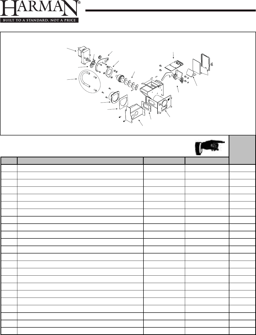
Service Parts P61A Pellet
Beginning Manufacturing Date: N/A
Ending Manufacturing Date: Active
IMPORTANT:THISISDATEDINFORMATION.Partsmustbeorderedfromadealerordistributor.
Hearth and Home Technologies does not sell directly to consumers.Providemodelnumber
andserialnumberwhenrequestingservicepartsfromyourdealerordistributor.
Stocked
at Depot
ITEM Description COMMENTS PART NUMBER
3 FeederAssembly Post008085803 1-10-09684A
3.1 PelletFeederGearMotor,4RPM 3-20-60906 Y
3.2 ULFeederCam 3-31-3014 Y
3.3 FeederAirCrossoverKit 1-00-67900 Y
9MMSiliconeTube 5Ft 1-00-511427 Y
3.4 PelletAirIntakeAssembly 1-10-06810A
3.5 GasketFeederAirIntake Pkgof6 3-44-72224-6 Y
3.6 ULFeederAirIntake 1-10-72228
3.7 GasketUltraAirIntake Pkgof10 3-44-677160-10 Y
3.8 UltraFeederWeldment 1-10-724132 Y
3.9 ULFeederPusherArm 1-10-677188W Y
3.10 FinesDeector No longer available 2-00-677138-10
3.11 Gasket,ULFeederCover 1-00-677122 Y
3.12 SlidePlateAssembly 1-10-677121A Y
3.13 ULFeederAugerAssembly 3-50-00565 Y
3.14 PelletFeederBearingRetainerw/Hardware Pkgof2 1-00-04035 Y
3.15 ULFeederGearMotorBracketw/Grommet 1-00-247406 Y
3.16 ULFeederCamBlock 3-00-677154 Y
Gasket,HopperThroat 3-44-677185 Y
HopperSwitchFeederFitting Pkgof2 1-00-142818 Y
MotorBracketGrommet Pkgof12 3-31-2761-12
PillowBlock Pkgof4 3-31-3614087-4 Y
SiliconeTubing,1/8” 5Ft 1-00-5113574 Y
Additionalservicepartsonfollowingpage.
3.7
3.6
3.5
3.4
3.3
3.2
3.1
3.16 3.15
3.8
3.9
3.10
3.11
3.12
3.13
3.14
#3 Post Serial Number 008085803 Feeder Assembly
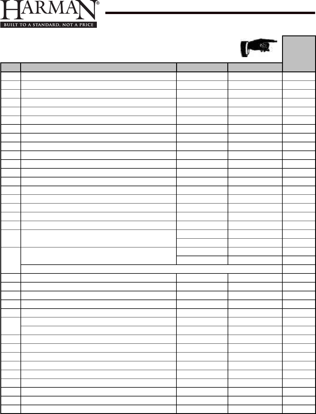
Service Parts P61A Pellet
Beginning Manufacturing Date: N/A
Ending Manufacturing Date: Active
IMPORTANT:THISISDATEDINFORMATION.Partsmustbeorderedfromadealerordistributor.
Hearth and Home Technologies does not sell directly to consumers.Providemodelnumber
andserialnumberwhenrequestingservicepartsfromyourdealerordistributor.
Stocked
at Depot
ITEM Description COMMENTS PART NUMBER
4FlueTailPipe 3-00-247237 Y
5AugerMotorCover 2-00-06470P Y
6AugerMotorShield 2-00-06467P Y
7DifferentialSwitch 3-20-6866 Y
8DistributionBlower 3-21-33647 Y
9CombustionMotor 3-21-08639 Y
CombustionBlowerGrommets&Spacers Pkgof25 1-00-960026
CombustionBlowerMountingScrews Pkgof100 1-00-53483208
10 RearCoverLeft 2-00-06468-1P Y
11 RearCoverRight 2-00-06468-2P Y
12 CombIntakeWeldment 1-10-08516S Y
13 RetainerAssembly 1-10-08533S Y
14 AshPan 1-10-05800 Y
15 AshDoorAssembly 1-10-06724S
16 BoltonHinge 2-00-06952B
17 CastDoorFrame 4-00-06800P
CastDoorw/Glass 1-10-06800A
18 GlassPanel 3-40-950133125 Y
GlassClipw/Hardware(Pkgof4) Pre00885001 1-00-773862
Post00885001 1-00-249140 Y
19 DoorHandleAssembly Pre13546 1-00-08704 Y
Post13546 1-00-453001 Y
Contains: Wooden Handle, Wave Washer, SHCS, Cast Handle, , SSS, Bhcs, Cast Pawl
WoodenHandlew/Hardware,LoadDoor 2Sets 1-00-00247 Y
20 BurnPotWeldment 1-10-05802 Y
FlameGuide 3-00-08534 Y
CleanOutCover 2Sets 1-00-06623 Y
ThumbScrew Pkgof10 3-31-782108-10 Y
21 FireBrick4-1/2x9x1-1/4" Pkgof7 1-00-900450125 Y
FireBrick,FullSkid 414Pcs 3-40-900450-414
22 HopperHeatShield 2-00-06471B
23 FeederCover 2-00-773826L
24 CircuitBoardw/Knobs&Shafts 1-00-05886 Y
CircuitBoardPlate,Studdedw/label 1-10-08327
ControlPanelLabel 3-90-06655A
Knob,ContolBoard/D-Shaft 25Sets 1-00-015605 Y
AirwashO-Rings Pkgof10 1-00-939639 Y
ArrowBurnPotScraper Pkgof10 2-00-773850-10
CastWeldonDoorHinge Qty2req 3-00-773813
Additionalservicepartsonfollowingpage.
Service Parts P61A Pellet
Beginning Manufacturing Date: N/A
Ending Manufacturing Date: Active
IMPORTANT:THISISDATEDINFORMATION.Partsmustbeorderedfromadealerordistributor. Hearth and
Home Technologies does not sell directly to consumers.Providemodelnumberandserialnumberwhen
requestingservicepartsfromyourdealerordistributor. Stocked
at Depot
ITEM Description COMMENTS PART NUMBER
CradleAssembly
IgniterHolder,Cradle,&atBottom 3sets 1-00-06620 Y
DiagnosticDisplayModule 3-20-05401 Y
DDMReplacementCable 1-00-05402
Disconnect,Female Pkgof25 1-00-00959 Y
DraftMeterAssembly 1-00-00637 Y
DraftMeterBoltandTube 1-00-04004
FanBlade,5”DoublePaddle(CombustionBlower) 3-20-502221 Y
Fuse,6Amp Pkgof5 3-20-49447-5 Y
Gasket,1/4”RopeBlackW/PSA(Glass) 15Ft 1-00-2312 Y
Gasket,3/8”RopeWhiteLD(AshorLoadDoor) 30Ft 1-00-00888 Y
Gasket,BurnPot/Tailpipe Pkgof5 1-00-07381 Y
Gasket,HopperLid 1-00-00248 Y
HopperLidW/Hinge 1-10-09109 Y
Igniter 3-20-677200 Y
Pkgof10 1-00-677200 Y
Labels,Caution&Danger 10ea 1-00-200408541
Label,Caution 3-90-00247
Latch,Swell/Hopperandspacer 1-00-199110 Y
RubberSpacer 3-31-901311-10
HopperMuferandFittings 1set 1-00-18186618 Y
OutsideAirVent 1-10-09542
PowerCord 3-20-39685 Y
RoomSensor 3-20-00906 Y
ThermostatExtension 3-20-00607 Y
ThermisterProbe(ESPProbe) Pre008085803 3-20-11744 Y
Post008085803 3-20-00844 Y
TouchupPaint,Black,12ozCan Pre008092412 3-42-1990
Post008092412 3-42-19905
WiringHarness 3-20-08727 Y
LeafDoorTrim
Gold 3-43-06802-4
BrushedStainless 3-43-06802-7
BrightNickel 3-43-06802-8
ModernDoorTrim BrushedStainless 3-43-06839-7
AshLipTrim
Gold 3-43-08400
BrushedStainless 3-43-08400-7
BrightNickel 3-43-08400-8
TileFrame
Gold 3-43-06729-4
BrushedStainless 3-43-06729-7
BrightNickel 3-43-06729-8
SpringClips(RequiredforinstallationofTileFrame) Pkgof20 3-31-232547-20

39 P61A Pellet Stove 3-90-05822R29_10/13
Service & Maintenance Log
Date Of Service Performed By Description Of Service

40P61A Pellet Stove
3-90-05822R29_10/13
Service & Maintenance Log
Date Of Service Performed By Description Of Service

41 P61A Pellet Stove 3-90-05822R29_10/13
Notes
Proudly Printed On 100% Recycled Paper
At Harman, we build each product to a standard, not a price.
This powerful heating appliance boasts uncompromising
attention to detail and helps preserve our planet by using
environmentally responsible fuels.
(Signature of Boxer)
Your premium quality hearth product designed and assembled
by the experienced and skilled members at Harman in Halifax,
PA, USA.
