Harrington Hoists Time Clock M3 Users Manual Report
M3 to the manual 88eb7d84-b8ec-4725-9021-4d0116bc0cb4
2015-02-09
: Harrington-Hoists Harrington-Hoists-Harrington-Hoists-Time-Clock-M3-Users-Manual-564049 harrington-hoists-harrington-hoists-time-clock-m3-users-manual-564049 harrington-hoists pdf
Open the PDF directly: View PDF ![]() .
.
Page Count: 56
-
MANUAL
CHAIN HOIST
CB SERIES
MODEL M3
1/2 Ton through 20 Ton Capacity
Code, Lot and Serial Number
EFFECTIVE: February 3, 2011
This equipment should not be installed, operated or
maintained by any person who has not read and understood
all the contents of this manual. Failure to read and comply
with the contents of this manual can result in serious bodily
injury or death, and/or property damage.

2
Table of Contents
1.0 Important Information and Warnings ……………………………………………………………………… 4
Section Page Number
1.1 Terms and Summary
1.2 Warning Tags and Labels
2.0 Technical Information…………………………………………………………………………….…………. 7
2.1 Specifications
2.2 Dimensions
2.3 Optional Equipment
3.0 Preoperational Procedures ……………………………………………………………………………… 11
3.1 Chain
3.2 Attachment Points
3.3 Mounting the Hoist
3.4 Preoperational Checks and Trial Operation
4.0 Operation …………………………………………………………………………………………………... 13
4.1 Introduction
4.2 Shall’s and Shall Not’s for Operation
4.3 Operation
4.4 Principal and Operation of the Slip Clutch
5.0 Inspection ………………………………………………………………………………………………….. 16
5.1 General
5.2 Inspection Classification
5.3 Frequent Inspection
5.4 Periodic Inspection
5.5 Occasionally Used Hoists
5.6 Inspection Records
5.7 Inspection Methods and Criteria

3
6.0 Maintenance & Handling …………………………………………………………………………………. 26
Section Page Number
6.1 Lubrication
6.2 Disassembly, Assembly and Adjustment
6.3 Hoist Disassembly
6.4 Hoist Assembly
6.5 Storage
6.6 Outdoor Installation
7.0 Troubleshooting …………………………………………………………………………………………… 36
8.0 Warranty …………………………………………………………………………………………………… 39
9.0 Parts List …………………………………………………………………………………………………… 41
4
1.0 Important Information and Warnings
1.1 Terms and Summary
This manual provides important information for personnel involved with the installation, operation and
maintenance of this product. Although you may be familiar with this or similar equipment, it is strongly
recommended that you read this manual before installing, operating, or maintaining the product.
Danger, Warning, Caution, and Notice
Throughout this manual there are steps and procedures that can present hazardous situations. The following
signal words are used to identify the degree or level of hazard seriousness.
Danger indicates an imminently hazardous situation which, if not avoided, will result in
death or serious injury, and property damage.
Warning indicates an imminently hazardous situation which, if not avoided, could result in
death or serious injury, and property damage.
Caution indicates a potentially hazardous situation which, if not avoided, may result in
minor or moderate injury or property damage.
Notice is used to notify people of installation, operation, or maintenance information which
is important but not directly hazard-related.
These general instructions deal with the normal installation, operation, and maintenance situations encountered with
the equipment described herein. The instructions should not be interpreted to anticipate every possible contingency
or to anticipate the final system, crane, or configuration that uses this equipment. For systems using the equipment
covered by this manual, the supplier and owner of the system are responsible for the system’s compliance with all
applicable industry standards, and with all applicable federal, state, and local regulations/codes.
This manual includes instructions and parts information for a variety of hoist types. Therefore, all instructions and
parts information may not apply to any one type or size of specific hoist. Disregard those portions of the instructions
that do not apply.
Record your hoist’s Code, Lot and Serial Number (see Section 9) on the front cover of this manual for identification
and future reference to avoid referring to the wrong manual for information or instructions on installation, operation,
inspection, maintenance, or parts.
Use only Harrington authorized replacement parts in the service and maintenance of this hoist.

5
Equipment described herein is not designed for and MUST NOT
be used for lifting, supporting, or transporting
people, or for lifting or supporting loads over people.
Equipment described herein should not be used in conjunction with other equipment unless necessary and/or
required safety devices applicable to the system, crane, or application are installed by the system designer, system
manufacturer, crane manufacturer, installer, or user.
Modifications to upgrade, rerate, or otherwise alter this equipment shall be authorized only by the original equipment
manufacturer.
If a below-the-hook lifting device or sling is used with a hoist, refer to ANSI/ASME B30.9, “Safety Standard for
Slings” or ANSI/ASME B30.20, “Safety Standard for Below-the-Hook Lifting Devices”.
Hoists used to handle hot molten material may require additional equipment or devices. Refer to ANSI Z241.2,
“Safety Requirements for Melting and Pouring of Metals in the Metalcasting Industry”.
Failure to read and comply with any one of the limitations noted herein can result in serious bodily injury or death,
and/or property damage.
It is the responsibility of the owner/user to install, inspect, test, maintain, and operate a hoist in accordance with
ANSI/ASME B30.16, “Overhead Hoists (Underhung)” and OSHA Regulations. If the hoist is installed as part of a
total lifting system, such as an overhead crane or monorail, it is also the responsibility of the owner/user to comply
with the applicable ANSI/ASME B30 volume that addresses that type of equipment.
It is the responsibility of the owner/user to have all personnel that will install, inspect, test, maintain, and operate a
hoist read the contents of this manual and applicable portions of ANSI/ASME B30.16, “Overhead Hoists
(Underhung)” and OSHA Regulations.
If the hoist owner/user requires additional information, or if any information in the manual is not clear, contact
Harrington or the distributor of the hoist. Do not install, inspect, test, maintain, or operate this hoist unless this
information is fully understood.
A regular schedule of inspection of the hoist in accordance with the requirements of ANSI/ASME B30.16 should be
established and records maintained.
6
1.2 Warning Tags and Labels
The warning tag illustrated below in Figure 1-1 is supplied with each hoist shipped from the factory. If the tag is
not attached to your hoist’s no-load side of the load chain, order a tag from your dealer and install it. Read and
obey all warnings attached to this hoist. Tag is not shown actual size.
Front Back
Figure 1-1 Warning Tag Attached to Hoist (shown larger for legibility)
7
2.0 Technical Information
2.1 Specifications
2.1.1 Product Code
2.1.2 Operating Conditions and Environment
Temperature range: -4° to +140°F (-20° to +60°C)
Humidity: 100% or less (Not an Underwater Device)
Table 2-1 Hoist Specifications
Cap.
(Tons)
Product
Code
Std.
Lift
(ft)
Pull to
Lift
Load
(lbs)
Load Chain
Diameter
(mm) x
Chain Fall
Lines
Overhaul
Ratio
Net
Weight
(lbs)
Shipping
Weight
Approx.
(lbs)
Weight for
Additional
One Foot
of Lift (lbs)
½ CB005
8
48 5.0x1 25 22 23 1.0
1 CB010 58 6.3x1 43 25 26 1.2
1½ CB015 70 7.1x1 57 32 33 1.4
2 CB020 72 8.0x1 70 41 43 1.6
2 ½ CB025 66 9.0x1 99 56 58 1.8
3 CB030 72 7.1x2 114 49 53 2.1
5 CB050 68 9.0x2 198 85 89 3.0
8 CB080 75 9.0x3 297 124 131 4.2
10 CB100
12
72 9.0x4 396 186 203 5.5
15 CB150 74 9.0x6 594 346 368 7.9
20 CB200 72x2 9.0x8 396x2 524 678 10.9
*NOTE: Any lift of chain is available on request. Simply specify the length of chain desired when ordering.
Because Harrington chains are specially heat treated, only authentic Harrington chains should be used on your
hoist. NEVER attempt to lengthen the chain by attaching additional chain links to it or by any other means.
8
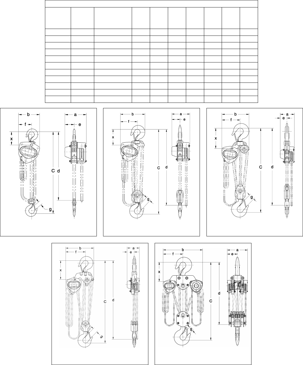
2.2 Dimensions
Table 2-2 Hoist Dimensions
Cap.
(Tons)
Product
Code
Headroom
c
(in)
a
(in)
b
(in)
d
(ft)
e
(in)
f
(in)
g
(in)
x
(in)
1/2 CB005 11.2 6.2 6.3 8.0 2.7 3.9 1.1 3.5
1 CB010 11.6 6.4 6.3 8.0 2.8 3.9 1.1 4.0
1 1/2 CB015 13.8 6.7 7.2 8.0 3.1 4.4 1.3 4.7
2 CB020 14.8 7.2 8.0 8.0 3.4 4.9 1.4 4.9
2 1/2 CB025 16.5 7.6 9.2 8.0 3.6 5.6 1.6 5.4
3 CB030 20.1 6.7 9.3 8.3 3.1 6.4 1.7 5.8
5 CB050 23.6 7.6 11.1 10.0 3.6 7.6 1.8 6.8
8 CB080 30.3 7.6 14.7 10.3 3.6 10.0 2.9 10.8
10 CB100 29.9 7.6 17.2 14.9 4.4 12.1 2.9 11.6
15 CB150 40.2 10.6 19.4 15.9 4.7 13.3 3.1 12.6
20 CB200 46.5 14.7 29.4 16.3 7.4 14.7 3.2 13.8
CB005 to CB025
CB030 to CB050
CB080
Figure 2-1
Figure 2-2
Figure 2-3
CB100 to CB150
CB200
Figure 2-4
Figure 2-5
9
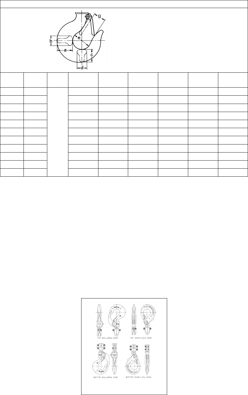
Table 2-3 Hook Dimension*
T = Top Hook
B = Bottom Hook
Units = inch
Cap.
(Tons)
Product
Code Hook a b c d e g
1/2 CB005
T & B
0.8 0.5 0.7 0.5 1.4 1.1
1 CB010 1.0 0.6 0.9 0.6 1.7 1.1
1½ CB015 1.2 0.8 1.0 0.8 1.9 1.3
2 CB020 1.4 0.9 1.2 0.9 2.0 1.4
2 ½ CB025 1.6 1.0 1.3 1.0 2.1 1.6
3 CB030 1.8 1.1 1.5 1.1 2.2 1.7
5 CB050 2.2 1.4 1.9 1.4 2.5 1.8
8 CB080 3.0 1.9 2.5 1.9 3.3 2.9
10 CB100 3.0 1.9 2.5 1.9 3.3 2.9
15 CB150 3.7 2.4 3.1 2.4 3.9 3.1
20 CB200 4.2 2.6 3.5 2.6 4.3 3.2
*Refer to Section 5.7 for inspection dimensions and limits.
2.3 Optional Equipment
2.3.1 Optional Latch Lock Hooks
The Bullard hook has a conventional hook shape with a special, heavy-duty, rotating, spring-
loaded, locking latch. The latch remains locked until it is released by the operator. Refer to Figure
2-6.
The Shur-Loc hook is a special design hook where the latch remains fixed and the hook swings
to unlock. The hook cannot be opened while a load is applied.
Installation of these hooks may change the headroom.
See Section 9.4, Parts List for a complete Latch Lock Hook part listing.
Figure 2-6 Latch Lock Hooks
10
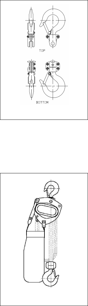
2.3.2 Optional Inspection Hooks
The Inspection Hook is designed to facilitate the inspection of the internal surfaces of the hook
yoke and shank portion of the hook itself. The Inspection Hook is suitable for applications where
inspection of the internal parts of the hook set is required. The inspection hook uses the standard
Harrington hook set and is assembled with high-strength locking fasteners instead of rivets.
Inspection hooks are available in top and bottom versions. Refer to Figure 2-7.
Disassembly and re-assembly involves removal and reinstallation of the yoke fasteners of the
Inspection Hook Set Assembly followed by testing of the hoist prior to returning it to service.
The Inspection Hook is available for CB005 through CB025 hoists.
See Section 9.4, Parts List for a complete Inspection Hook part listing.
Figure 2-7 Inspection Hooks
2.3.3 Optional Chain Containers
Chain containers are sized based on the capacity and lift of the hoist. The containers are
constructed from vinyl coated canvas with a steel frame on top. The containers are prepared
differently depending on the host model. See Harrington document EDOC0154 for sizing
information.
Figure 2-8 CB Chain Container
11
3.0 Preoperational Procedures
3.1 Chain
3.1.1
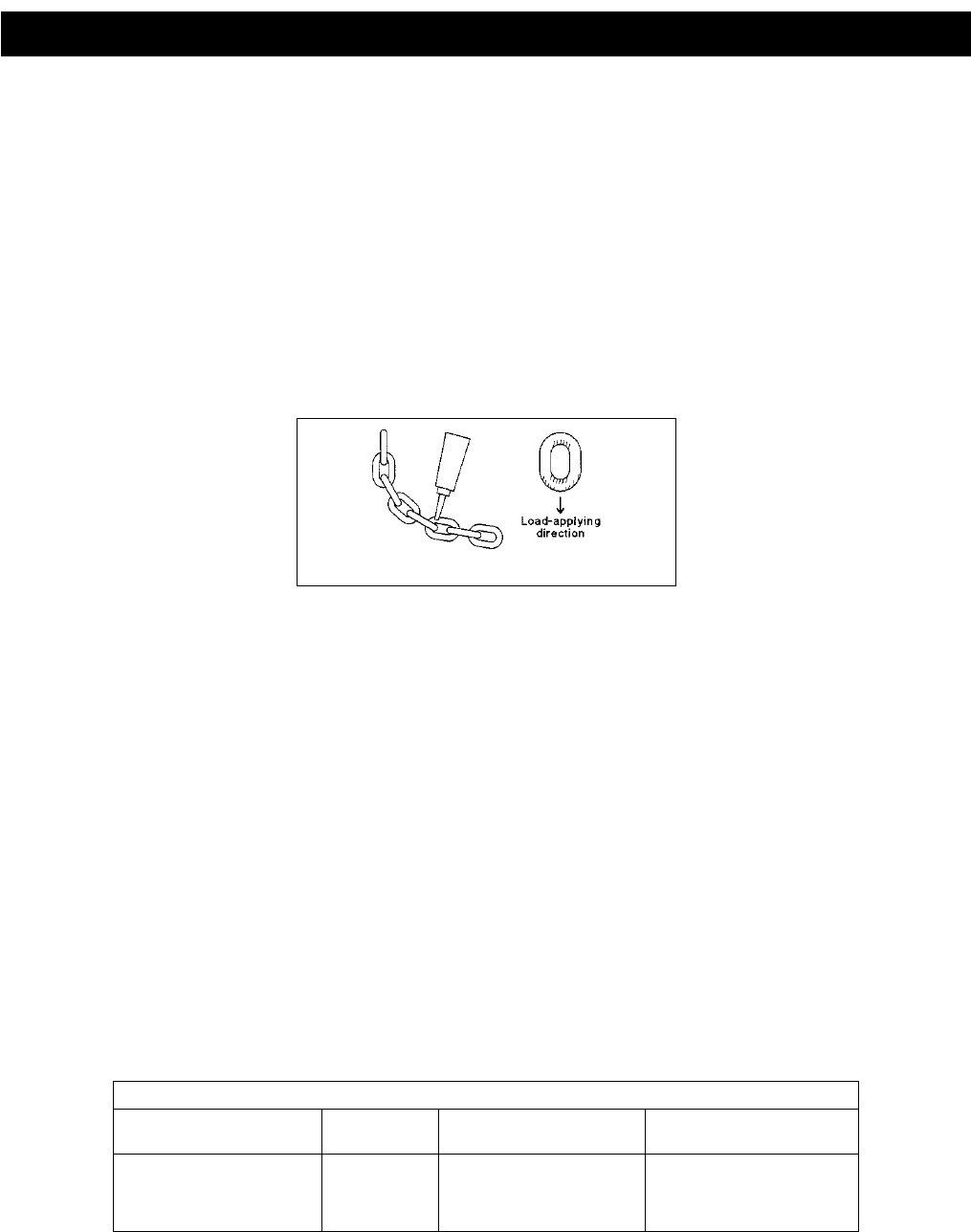
Verify that the load chain is not twisted or tangled prior to operating the hoist.
Make sure the bottom hook on the 3 (CB030) through the 20 (CB200) Ton multiple fall hoists is not
capsized. See Figures 3-1 and 3-2. Correct all chain irregularities before conducting the first hoist
operation.
Figure 3-1 Twist in Load Chain – Double Fall Model
Figure 3-2 Capsized Hook and Chain – Double Fall Model
12
3.2 Attachment Points
3.2.1
Prior to attaching the hoist ensure that all attachment points, suspension
components and supporting structure are adequate to support the hoist and its load. If necessary
consult a professional that is qualified to evaluate the adequacy of the suspension location and its
supporting structure.
3.2.2
See Section 6.6 for outdoor installation considerations.
3.3 Mounting the Hoist
3.3.1 Hook Mounted to a Fixed Location - Attach the hoist’s top hook to the fixed suspension point.
3.3.2
Ensure that the fixed suspension point rests on the center of the hook’s saddle and
that the hook’s latch is engaged.
3.4 Preoperational Checks and Trial Operation
3.4.1
Confirm the adequacy of the rated capacity for all slings, chains, wire ropes and all
other lifting attachments before use. Inspect all load suspension members for damage prior to use and
replace or repair all damaged parts.
3.4.2
Verify and correct all chain irregularities prior to operating the hoist. Refer to
Section 3.1.
3.4.3 Measure and record the “k” dimension of all hooks on hoist. See Table 5-4 under Section 5,
“Inspection”.
3.4.4 Record the hoist's Code, Lot and Serial Number (from the name plate on the hoist; see Section 9) in
the space provided on the cover of this manual.
3.4.5 Ensure that the hoist is properly installed to a fixed point.
3.4.6 Ensure that all nuts, bolts and split pins (cotter pins) are sufficiently fastened.
3.4.7 Confirm proper operation.
Before operating read and become familiar with Section 4 - Operation.
Before operating ensure that the hoist meets the Inspection, Testing and Maintenance
requirements of ANSI/ASME B30.16.
Before operating ensure that nothing will interfere with the full range of the hoist’s operation.
13
4.0 Operation
4.1 Introduction
DO NOT
WALK UNDER A SUSPENDED LOAD
HOIST OPERATORS SHALL BE REQUIRED TO READ THE OPERATION SECTION OF THIS MANUAL, THE
WARNINGS CONTAINED IN THIS MANUAL, INSTRUCTION AND WARNING LABELS ON THE HOIST OR
LIFTING SYSTEM, AND THE OPERATION SECTIONS OF ANSI/ASME B30.16 and ANSI/ASME B30.10. THE
OPERATOR SHALL ALSO BE REQUIRED TO BE FAMILIAR WITH THE HOIST AND HOIST CONTROLS
BEFORE BEING AUTHORIZED TO OPERATE THE HOIST OR LIFTING SYSTEM.
HOIST OPERATORS SHOULD BE TRAINED IN PROPER RIGGING PROCEDURES FOR THE ATTACHMENT
OF LOADS TO THE HOIST HOOK.
HOIST OPERATORS SHOULD BE TRAINED TO BE AWARE OF POTENTIAL MALFUNCTIONS OF THE
EQUIPMENT THAT REQUIRE ADJUSTMENT OR REPAIR, AND TO BE INSTRUCTED TO STOP OPERATION
IF SUCH MALFUNCTIONS OCCUR, AND TO IMMEDIATELY ADVISE THEIR SUPERVISOR SO CORRECTIVE
ACTION CAN BE TAKEN.
HOIST OPERATORS SHOULD HAVE NORMAL DEPTH PERCEPTION, FIELD OF VISION, REACTION TIME,
MANUAL DEXTERITY, AND COORDINATION.
HOIST OPERATORS SHOULD NOT
HAVE A HISTORY OF OR BE PRONE T
O SEIZURES, LOSS OF
PHYSICAL CONTROL, PHYSICAL DEFECTS, OR EMOTIONAL INSTABILITY THAT COULD RESULT IN
ACTIONS OF THE OPERATOR BEING A HAZARD TO THE OPERATOR OR TO OTHERS.
HOIST OPERATORS SHOULD NOT
OPERATE A HOIST OR LIFTING SYSTEM WHEN UNDER THE
INFLUENCE OF ALCOHOL, DRUGS, OR MEDICATION.
• Read ANSI/ASME B30.16 and ANSI/ASME B30.10.
• Read the hoist manufacturer’s Operating and Maintenance Instructions.
• Read all labels attached to equipment.
The operation of a hoist involves more than activating the hoist’s controls. Per the ANSI/ASME B30 standards, the use
of a hoist is subject to certain hazards that cannot be mitigated by engineered features, but only by the exercise of
intelligence, care, common sense, and experience in anticipating the effects and results of activating the hoist’s controls.
Use this guidance in conjunction with other warnings, cautions, and notices in this manual to govern the operation and
use of your hoist.
14
4.2 Shall’s and Shall Not’s for Operation
Improper operation of a hoist can create a potentially hazardous
situation which, if not avoided, could result in death or serious injury
,
and substantial property damage. To avoid such a potentially
hazardous situation THE OPERATOR SHALL:
• NOT
•
lift more than rated load for the hoist.
NOT
•
use damaged hoist or hoist that is not working
properly.
NOT
•
use hoist with twisted, kinked, damaged, or
worn chain.
NOT
•
use hoist if the bottom hook is capsized
(multiple fall hoists - see Section 3.1).
NOT
•
use the hoist to lift, support, or transport
people.
NOT
•
lift loads over people.
NOT
•
apply load unless load chain is properly
seated in the load sheave (and idle sheave for hoist
with multiple chain falls).
NOT
•
use the hoist in such a way that could result in
shock or impact loads being applied to the hoist.
NOT
•
attempt to lengthen the load chain or repair
damaged load chain.
NOT
•
operate hoist when it is restricted from forming
a straight line from hook to hook in the direction of
loading.
NOT
•
use load chain as a sling or wrap load chain
around load.
NOT
•
apply load if binding prevents equal loading
on all load-supporting chains.
NOT
•
operate beyond the limits of the load chain
travel.
NOT
•
support load on hook tip unless hook is
designed for tip loading.
NOT
use in a way that causes either hook to be
side-loaded.
• NOT
•
leave load supported by the hoist unattended
unless specific precautions have been taken.
NOT
•
allow the chain, or hook to be used as an
electrical or welding ground.
NOT
•
allow the chain, or hook to be touched by a
live welding electrode.
NOT
•
remove or obscure the warnings on the hoist.
NOT
• Be familiar with operating controls, procedures, and
warnings.
operate a hoist on which the safety placards
or decals are missing or illegible.
• Make sure the unit is securely attached to a
suitable support before applying load.
• Make sure load slings or other approved single
attachments are properly sized, rigged, and seated
in the hook saddle.
• Take up slack carefully - make sure load is
balanced and load-holding action is secure before
continuing.
• Make sure all persons stay clear of the supported
load.
• Protect the hoist’s load chain from weld splatter or
other damaging contaminants.
• Report Malfunctions or unusual performances
(including unusual noises) of the hoist and remove
the hoist from service until the malfunction or
unusual performance is resolved.
• Warn personnel before lifting or moving a load.
• Warn personnel of an approaching load.

15
Improper operation of a hoist can create a potentially hazardous
situation which, if not avoided, could result in minor or moderate
injury
• Maintain a firm footing or be otherwise secured
when operating the hoist.
• Check brake function by tensioning the hoist prior
to each lift operation.
• Use hook latches. Latches are to retain slings,
chains, etc. under slack conditions only.
• Make sure the hook latches are closed and not
supporting any parts of the load.
• Make sure the load is free to move and will clear all
obstructions.
• Avoid swinging the load or hook.
• Make sure hook travel is in the same direction as
shown on controls.
, or property damage. To avoid such a potentially hazardous
situation THE OPERATOR SHALL:
• Inspect the hoist regularly, replace damaged or
worn parts, and keep appropriate records of
maintenance.
• Use the hoist manufacturer’s recommended parts
when repairing the unit.
• Lubricate load chain per hoist manufacturer’s
recommendations.
• NOT
•
use the hoist load limiting or warning device to
measure load.
NOT
•
allow your attention to be diverted from
operating the hoist.
NOT
•
allow the hoist to be subjected to sharp
contact with other hoists, structures, or objects
through misuse.
NOT
perform such adjustments or repair.
adjust or repair the hoist unless qualified to
4.3 Operation
1) Face the hand chain wheel side of the hoist.
2) To raise the load, pull hand chain clockwise.
3) To lower the load, pull hand chain counterclockwise.
NOTE: The clicking sound of the pawl when a load is being raised indicates normal operation.
4.4 Principle and Operation of the Slip Clutch
: IMPROPER chain hoist use could result in death or serious injury. To avoid these hazards:
: NEVER disassemble or attempt to adjust the slip clutch assemby. Any attempt to do so will void
the warranty. Contact your closest Harrington Distributor if service is required.
The standard slip clutch device prevents the hoist from being used to lift damaging loads beyond the rated capacity of
the manual chain hoist. When an applied load exceeds the preset value, the hand chain wheel rotates idly. The
mechanism is a friction clutch system located between the hand chain wheel and the mechanical brake.

16
5.0 Inspection
5.1 General
5.1.1 The inspection procedure herein is based on ANSI/ASME B30.16. The following definitions are from
ANSI/ASME B30.16 and pertain to the inspection procedure below.
Designated Person
– a person selected or assigned as being competent to perform the specific
duties to which he/she is assigned.
Qualified Person
– a person who, by possession of a recognized degree or certificate of
professional standing, or who, by extensive knowledge, training, and experience, has successfully
demonstrated the ability to solve or resolve problems relating to the subject matter and work.
Normal Service
– that distributed service which involves operation with randomly distributed loads
within the rated load limit, or uniform loads less than 65% of rated load for not more than 15% of
the time.
Heavy Service
– that service which involves operation within the rated load limit which exceeds
normal service.
Severe Service
5.2 Inspection Classification
– that service which involves normal or heavy service with abnormal operating
conditions.
5.2.1 Initial Inspection – prior to initial use, all new, altered, or modified hoists shall be inspected by a
designated person to ensure compliance with the applicable provisions of this manual.
5.2.2 Inspection Classification – the inspection procedure for hoists in regular service is divided into two
general classifications based upon the intervals at which inspection should be performed. The intervals
in turn are dependent upon the nature of the critical components of the hoist and the degree of their
exposure to wear, deterioration, or malfunction. The two general classifications are herein designated
as FREQUENT and PERIODIC, with respective intervals between inspections as defined below.
5.2.3 FREQUENT Inspection – visual examinations by the operator or other designated personnel with
intervals per the following criteria:
Normal service – monthly
Heavy service – weekly to monthly
Severe service – daily to weekly
Special or infrequent service – as recommended by a qualified person before and after each
occurrence.
5.2.4 PERIODIC Inspection – visual inspection by a designated person with intervals per the following
criteria:
Normal service – yearly
Heavy service – semiannually
Severe service – quarterly
Special or infrequent service – as recommended by a qualified person before the first such
occurrence and as directed by the qualified person for any subsequent occurrences.

17
5.3 Frequent Inspection
5.3.1 Inspections should be made on a FREQUENT basis in accordance with Table 5-1, “Frequent
Inspection.” Included in these FREQUENT Inspections are observations made during operation for
any defects or damage that might appear between Periodic Inspections. Evaluation and resolution of
the results of FREQUENT Inspections shall be made by a designated person such that the hoist is
maintained in safe working condition.
Table 5-1 Frequent Inspection
All functional operating mechanisms for proper operation and adjustment, maladjustment and
unusual sounds.
Hoist braking system for proper operation
Hooks and latches in accordance with ANSI/ASME B30.10
Hook latch operation
Load chain in accordance with Section 5.7
Load chain reeving for compliance with Section 3.1 and 6.4
Hoist support for damage
5.4 Periodic Inspection
5.4.1 Inspections should be made on a PERIODIC basis in accordance with Table 5-2, “Periodic Inspection.”
Evaluation and resolution of the results of PERIODIC Inspections shall be made by a designated
person such that the hoist is maintained in safe working condition.
5.4.2 For inspections where load suspension parts of the hoist are disassembled, a load test per ANSI/ASME
B30.16 must be performed on the hoist after it is re-assembled and prior to its return to service.
Table 5-2 Periodic Inspection
Requirements of frequent inspection.
Evidence of loose bolts, nuts, or rivets.
Evidence of worn, corroded, cracked, or distorted parts such as load blocks, suspension housing,
chain attachments, clevises, yokes, suspension bolts, shafts, gears, bearings, pins, rollers and
locking and clamping devices.
Evidence of damage to hook retaining nuts or collars and pins, and welds or rivets used to secure
the retaining members.
Evidence of damage or excessive wear of load and idler sheaves.
Evidence of worn, glazed or oil contaminated friction disks; worn pawls, cams or ratchet; corroded,
stretched, or broken pawl springs in brake mechanism.
Evidence of damage to supporting structure.
Function label on hoist for legibility.
Warning label properly attached to the hoist and legible (see Section 1.2).
End connection of load chain.

18
5.5 Occasionally Used Hoists
5.5.1 Hoists that are used infrequently shall be inspected as follows prior to placing in service:
Hoist Idle More Than 1 Month, Less Than 1 Year
: Inspect per FREQUENT Inspection criteria in
Section 5.3.
Hoist Idle More Than 1 Year
5.6 Inspection Records
: Inspect per PERIODIC Inspection criteria in Section 5.4.
5.6.1 Dated inspection reports and records should be maintained at time intervals corresponding to those
that apply for the hoist’s PERIODIC interval per Section 5.2.4. These records should be stored where
they are available to personnel involved with the inspection, maintenance, or operation of the hoist.
5.6.2 A long range chain inspection program should be established and should include records of
examination of chains removed from service so a relationship can be established between visual
observation and actual condition of the chain.
5.7 Inspection Methods and Criteria
5.7.1 This section covers the inspection of specific items. The list of items in this section is based on those
listed in ANSI/ASME B30.16 for the Frequent and Periodic Inspection.
5.7.2 Frequent Inspection - Not intended to involve disassembly of the hoist. Disassembly for further
inspection would be required only if frequent inspection results so indicate. Disassembly and further
inspection should only be performed by a qualified person trained in the disassembly and re-assembly
of the hoist.
5.7.3 Periodic Inspection - Disassembly of the hoist is required. Disassambly should only be performed by a
qualified person trained in the disassembly and re-assembly of the hoist.
Table 5-3 Hoist Inspection Methods and Criteria
Item Method Discard Limit/Criteria Action
Functional operating
mechanisms. Visual, Auditory Mechanisms should be properly adjusted and
should not produce unusual sounds when operated.
Components should not be deformed, scarred, or
show significant wear. Refer to Figures 5-2, 5-3 and
5-4.
Repair or replace
as required.
Hooks – Stretch Measure The "k" dimension should not be greater than 1.05
times that measured and recorded at the time of
purchase (See Section 3.4). If recorded "k" values
are not available for hooks when new, use nominal
"k" values from Table 5-4.
Replace.
Hooks – Fretting
wear Measure The "u" and "t" dimensions should not be less than
discard value listed in Table 5-4. Replace.
Hooks – Surface
Condition Visual Should be free of gouges, deep nicks, dents, weld
splatter, and significant corrosion. Replace.
Hooks –
Deformation Visual Should be free of twists and deformations. See
Figure 5-1. Replace.
Hooks – Bent Shank
or Neck Visual Shank and neck portions of hook should be free of
deformations. Replace.
Hooks – Swivel Visual, Function Bearing parts and surfaces should not show
significant wear, and should be free of dirt, grime,
and deformations. Hook should rotate freely with no
roughness. See Figure 5-1.
Clean/lubricate, or
replace as required.

19
Table 5-3 Hoist Inspection Methods and Criteria
Item Method Discard Limit/Criteria Action
Hooks – Yoke
Assembly Visual Should be free of significant rust, weld splatter,
nicks, and gouges. Holes should not be elongated,
fasteners should not be loose, and there should be
no gap between mating parts.
Tighten or replace
as required.
Hooks – Idle Sheave
and Shaft (Multiple
Fall Hoist)
Visual, Function Pockets of Idle Sheave should be free of significant
wear. Idle Sheave surfaces should be free of nicks,
gouges, dirt, and grime. Bearing parts and surfaces
of Idle Sheave and Axle should not show significant
wear. Idle Sheave should rotate freely with no
roughness or significant free play.
Clean/lubricate, or
replace as required.
Hooks – Hook
Latches Visual, Function Latch should not be deformed. Attachment of latch
to hook should not be loose. Latch spring should
not be missing and should not be weak. Latch
movement should not be stiff - when depressed and
released latch should snap smartly to its closed
position.
Replace.
Yoke – Top Pin Hole
Deformation Visual, Measure The "d" dimension of the top pin hole should not be
greater than the discard value listed in Table 5-5. Replace Hook Set
Top Pin –
Deformation Visual, Measure The pin should be free of scars or significant
deformation. The “d" dimension should not be less
than discard value listed in Table 5-6.
Replace
Yoke – Chain Pin
Hole Deformation Measure The "d" dimension of the chain pin hole should not
be greater than the discard value listed in Table 5-5. Replace Hook Set
or yoke.
Chain Pin –
Deformation Visual, Measure The pin should be free of scars or significant
deformation. The “d" dimension should not be less
than discard value listed in Table 5-7.
Replace
Load Chain – Pitch
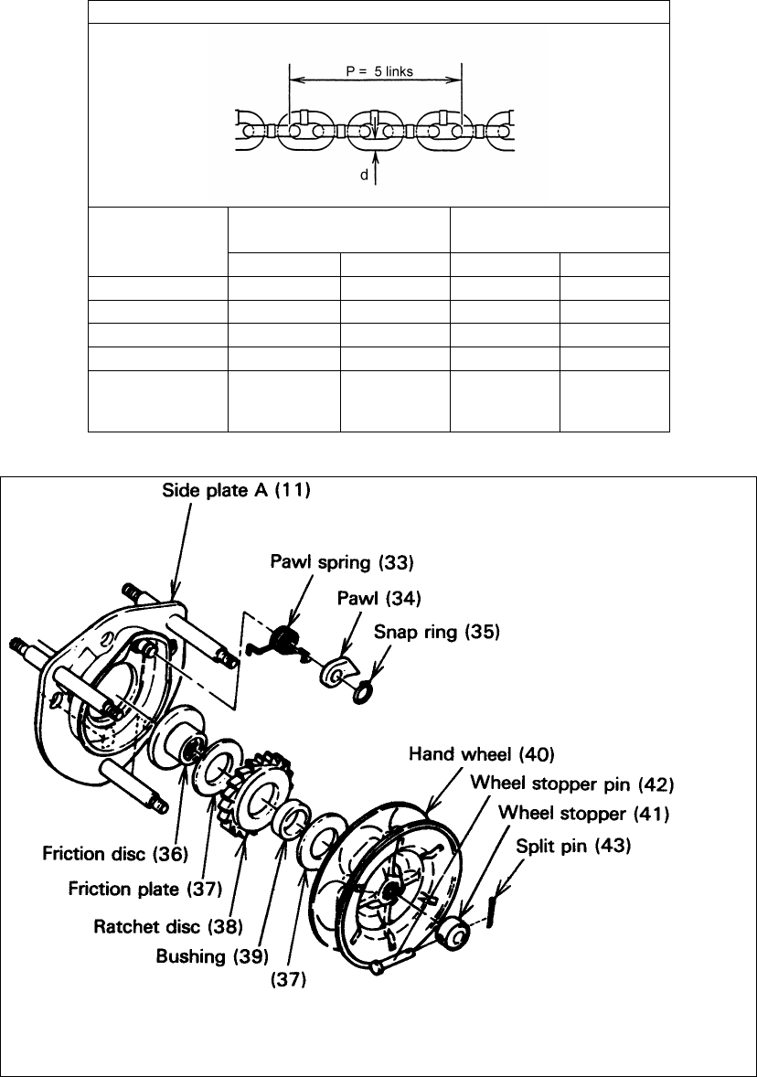
and Wire Diameter Measure The "P" dimension should not be greater than
discard value listed in Table 5-8. The "d" dimension
should not be less than discard value listed in Table
5-8.
Replace. Inspect
Load Sheave (and
Idle Sheave for
multiple fall hoists).
Load Chain –
Surface Condition Visual Should be free of gouges, nicks, dents, weld
splatter, and corrosion. Links should not be
deformed, and should not show signs of abrasion.
Surfaces where links bear on one another should
be free of significant wear.
Replace.
Load Chain –
Lubrication Visual, Auditory Entire surface of each chain link should be coated
with lubricant and should be free of dirt and grime.
Chain should not emit cracking noise when hoisting
a load.
Clean/lubricate (see
Section 6.0).
Load Chain –
Reeving Visual Chain should be reeved properly through Load
Sheave. On multiple fall hoists chain should be
installed properly and free of twists. Refer to
Section 3.1.
Reeve/Install chain
properly.
Lifting System –
Components Visual, Function Components should not be deformed, scarred, or
show significant wear. Replace.

20
Table 5-3 Hoist Inspection Methods and Criteria
Item Method Discard Limit/Criteria Action
Braking System –
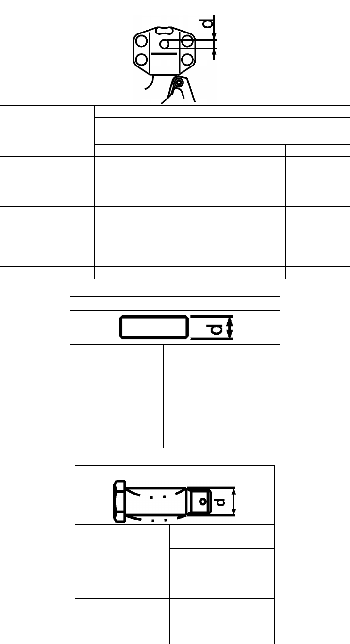
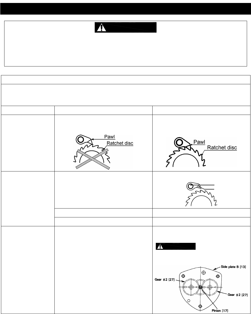
Components Visual Brake Pawl, Pawl Pin, and Pawl Spring should not
be deformed, scarred, or show significant wear.
Refer to Figure 5-2 (34 & 33).
Replace.
Brake – Damage to
Brake Surface Visual Damage due to scratching or gouging by foreign
matter. Refer to Figure 5-2 (37, 38, & 40). Replace.
Braking System –
Friction Disc Visual The surface of the friction plate should be free of
scars, gouges, and wear. Refer to Figure 5-2 (36). Replace.
Braking System –
Friction Plate Visual, Measure The surface of the friction plate should be free of
grease, oil, scars, gouges and wear and have
uniform thickness. The outer thickness should not
be thinner than the inner thickness. The thickness
should not be less than the discard value listed in
Table 5-9.
Replace.
Braking System –
Bushing Measure The bushing should have uniform thickness. The “t”
dimension should not be less than the discard value
listed in Table 5-10.
Replace.
Braking System –
Bushing Visual When slightly heated, the bushing should be so
lubricated that lubricant oozes off the surface. Refer
to Figure 5-2 (39). Type of oil to be used: ISO
VG68 or equivalent.
Soak bushing in
machine oil for one
day.
Braking System –
Ratchet Disc Measure The “D” dimension should not be less than the
discard value listed in Table 5-11.
Refer to Figure 5-2 (38).
Replace.
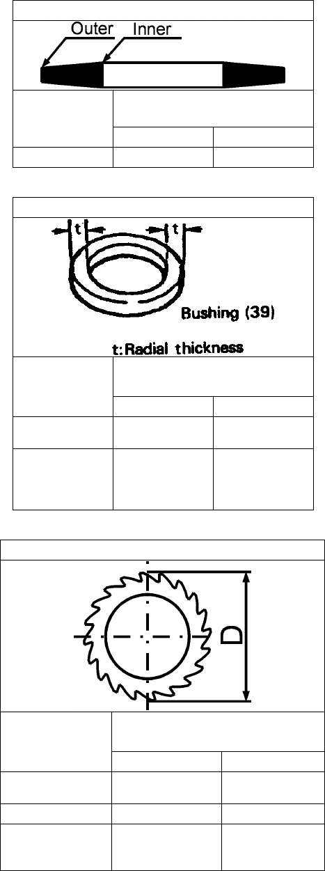
Load Sheave Visual Pockets of Load Sheave should be clean and free
of significant wear. Refer to Figure 5-3 (14). Replace.
Load Gear Visual Teeth have excessive wear or damage. Refer to
Figure 5-4 (25). Replace.
Hand Wheel Visual Large wear or deformation on the surface of hand
wheel. The hand wheel touches the cover. Replace.
Frame and
Mechanical
Components
Visual, Auditory,
Function Hoist components including load blocks,
suspension frame, chain attachments, clevises,
yokes, suspension bolts, shafts, gears, bearings,
stripper, pins, and rollers should be free of cracks,
distortion, significant wear, and corrosion. Evidence
of same can be detected visually or via detection of
unusual sounds during operation. Refer to Figures
5-4 & 5-5.
Replace.
Chain Guide Visual Excessive wear or press mark. Replace.
Bolts, Nuts and
Rivets
Visual, Check
with Proper Tool
Bolts, nuts, and rivets should not be loose,
deformed, or corroded. Tighten or replace
as required.
Warning Labels Visual Warning Labels should be affixed to the hoist (see
Section 1.2) and they should be legible. Replace.
Hoist Capacity Label Visual The label that indicates the capacity of the hoist
should be legible and securely attached to the hoist. Replace.
21
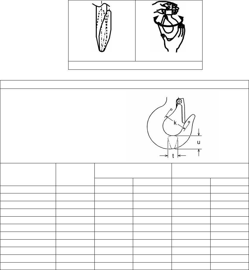
Twisted Hook
Hook Swivel
Figure 5-1 Top & Bottom Hook Checks
Table 5-4 Top Hook & Bottom Hook Dimensions
“k” Measured When New:
Top: _________________________
Bottom: ______________________
Product Code Nominal "k"
Dimension*
inch (mm)
"u" Dimension
inch (mm)
"t" Dimension
inch (mm)
Standard
Discard
Standard
Discard
CB005 1.76 (44.6) 0.67 (17.0) 0.60 (15.3) 0.48 (12.1) 0.43 (10.9)
CB010 1.92 (48.8) 0.86 (21.8) 0.77 (19.6) 0.63 (16.0) 0.57 (14.4)
CB015 2.22 (56.3) 1.04 (26.5) 0.94 (23.9) 0.77 (19.5) 0.69 (17.6)
CB020 2.36 (59.9) 1.18 (30.0) 1.06 (27.0) 0.86 (21.8) 0.77 (19.6)
CB025 2.52 (64.1) 1.32 (33.5) 1.19 (30.2) 0.96 (24.3) 0.86 (21.9)
CB030 2.72 (69.1) 1.48 (37.5) 1.33 (33.8) 1.07 (27.2) 0.97 (24.5)
CB050 3.06 (77.8) 1.87 (47.5) 1.69 (42.8) 1.36 (34.5) 1.22 (31.1)
CB080 4.56 (115.9) 2.48 (63.0) 2.23 (56.7) 1.87 (47.5) 1.69 (42.8)
CB100 4.56 (115.9) 2.48 (63.0) 2.23 (56.7) 1.87 (47.5) 1.69 (42.8)
CB150 5.52 (140.2) 3.15 (80.0) 2.84 (72.0) 1.97 (50.0) 1.77 (45.0)
CB200 5.62 (142.8) 3.54 (90.0) 3.19 (81.0) 2.21 (56.0) 2.09 (53.1)
*These values are nominal since the dimension is not controlled to a tolerance. The "k"
dimension should be measured when the hook is new - this becomes a reference measurement.
Subsequent measurements are compared to this reference to make determinations about hook
deformation/stretch. See Section 5.7, “Hooks - Stretch”.
22
Table 5-5 Chain Pin Hole and Top Pin Hole Wear Dimensions
Product Code
Hole Diameter (d)
Chain Pin Hole
inch (mm)
Top Pin Hole
inch (mm)
Standard Discard Standard Discard
CB005 0.252 (6.4) 0.272 (6.9) 0.480 (12.2) 0.500 (12.7)
CB010 0.319 (8.1) 0.339 (8.6) 0.480 (12.2) 0.500 (12.7)
CB015 0.350 (8.9) 0.370 (9.4) 0.638 (16.2) 0.658 (16.7)
CB020 0.394 (10.0) 0.413 (10.5) 0.638 (16.2) 0.658 (16.7)
CB025 0.445 (11.3) 0.465 (11.8) 0.638 (16.2) 0.658 (16.7)
CB030 0.350 (8.9) 0.370 (9.4) 0.646 (16.4) 0.665 (16.9)
CB050, CB080,
CB100 0.445 (11.3) 0.465 (11.8) 0.646 (16.4) 0.665 (16.9)
CB150 0.445 (11.3) 0.465 (11.8) 0.638 (16.2) 0.658 (16.7)
CB200 N/A N/A 0.638 (16.2) 0.658 (16.7)
Table 5-6 Body Top Pin Wear Dimensions
Product Code
“d” Dimension
inch (mm)
Standard Discard
CB005, CB010 0.472 (12) 0.433 (11)
CB015, CB020,
CB025, CB030,
CB050, CB080,
CB100, CB150,
CB200
0.630 (16) 0.591 (15)
Table 5-7 Chain Pin Wear Dimensions
Product Code
“d” Dimension
inch (mm)
Standard Discard
CB005 0.244 (6.2) 0.232 (5.9)
CB010 0.311 (7.9) 0.295 (7.5)
CB015, CB030 0.343 (8.7) 0.327 (8.3)
CB020 0.386 (9.8) 0.370 (9.4)
CB025, CB050,
CB080, CB100,
CB150
0.437
(11.1) 0.417
(10.6)
23
Figure 5-2 Brake Assembly
Table 5-8 Chain Wear Dimensions
Product Code
“P” Dimension
inch (mm)
“d” Dimension
inch (mm)
Standard Discard Standard Discard
CB005 2.97 (75.5) 3.06 (77.7) 0.20 (5.0) 0.18 (4.5)
CB010 3.76 (95.5) 3.87 (98.3) 0.25 (6.3) 0.22 (5.7)
CB015, CB030 4.17 (106.0) 4.30 (109.1) 0.28 (7.1) 0.25 (6.4)
CB020 4.76 (121.0) 4.91 (124.6) 0.32 (8.0) 0.28 (7.2)
CB025, CB050,
CB080, CB100,
CB150, CB200 5.35 (136.0) 5.51 (140.0) 0.35 (9.0) 0.32 (8.1)
24
Table 5-9 Friction Plate Wear Dimensions
Product Code
Thickness
inch (mm)
Standard
Discard
All 0.118 (3.0) 0.098 (2.5)
Table 5-10 Brake Bushing Wear Dimensions
Product Code
A Dimension
inch (mm)
Standard Discard
CB005, CB010,
CB015, CB030 0.118 (3.0) 0.079 (2.0)
CB020, CB025,
CB050, CB080,
CB100, CB150,
CB200
0.157 (4.0) 0.118 (3.0)
Table 5-11 Brake Ratchet Disc Wear Dimensions
Product Code
D Dimension
inch (mm)
Standard Discard
CB005, CB010,
CB015, CB030 2.71 (69) 2.60 (66)
CB020 3.23 (82) 3.11 (79)
CB025, CB050,
CB080, CB100,
CB150, CB200 4.65 (118) 4.53 (115)
25
Figure 5-3 Pocket Wheel
Figure 5-4 Load Gear Assembly
Figure 5-5 Top Hook Assembly
26
6.0 Maintenance and Handling
6.1 Lubrication
6.1.1 Load Chain
For longer life, the load chain should be lubricated.
The load chain lubrication should be accomplished after cleaning the load chain with an acid free
cleaning solution.
Apply Harrington lubricating grease (Part No. ER1BS1951) or an equivalent to industrial general
lithium grease, NLGI No. 0, to the bearing surfaces of the load chain links as indicated by the
shaded areas in Figure 6-1. Also apply the grease to the areas of the load chain (shaded areas in
Figure 6-1) that contact the load sheave. Insure that the grease is applied to the contact areas in
the load sheave pockets.
Machine or gear oil (grade ISO VG 46 or 68 oil or equivalent) may be used as an alternative
lubricant but must be applied more frequently.
Figure 6-1 Chain Grease Application
The chain should be lubricated every 3 months (more frequently for heavier usage or severe
conditions).
For dusty environments, it is acceptable to substitute a dry lubricant.
6.1.2 Hooks and Suspension Components:
Hooks – Bearings should be cleaned and lubricated at least once per year for normal usage.
Clean and lubricate more frequently for heavier usage or severe conditions.
Hook Yokes and Latches – Lubricate the hook yokes and hook latches at least twice per year for
normal usage; more frequently for heavier usage or severe conditions.
Suspension Pins - Lubricate the chain pin and the top pin at least twice per year for normal usage;
more frequently for heavier usage or severe conditions.
6.1.3 Applying Grease to Gears:
Remove gear case as instructed in Section 6.3.
Remove old grease and replace the new grease (NLGI No. 3), at annual inspection.
Temperature range of standard grease is -20˚C (-4˚F) to + 60˚C (140˚F). If the hoist is used at
temperatures below -20˚C (-4˚F) or above 60˚C (140˚F), consult the manufacturer or dealer since
some parts should be changed.
Table 6-1 General Lubrication
Parts to be Lubricated Name of Oil Amount of Lubrication
and Lubricating Method Frequency of
Lubrication
Mechanical Brake Parts:
Ratchet Disc, Pawl Pin,
Screw parts of Pinion
Machine or
Gear Oil
Wipe off oil with waste
cloth after applying
proper amount of oil.
When the hand pull
becomes extremely heavy
in lowering operations.

27
6.2 Disassembly, Assembly and Adjustment
6.2.1
1) Perform proper disassembly or assembly in accordance with this manual.
2) The hoist utilizes dry friction plates; they are not to be lubricated.
3) Do not extend the load chain.
4) Remove old grease on the disassembled parts.
5) Replace components with Harrington Hoist approved parts.
6) To reassemble, apply new grease, and use a new split pin and snap ring.
6.2.2 Tools – The following tools are required to disassemble/reassemble the hoist.
Table 6-2 Tools Required for Hoist Disassembly
No. Tool Operation
1 Snap ring pliers Opening a snap ring
2 Metric socket wrenches Slotted nuts
3 Metric hex keys (Allen wrenches) Socket head cap screws
4 Metric wrenches Bolts and nuts
5 Phillips screwdriver Machine screws
6 Pliers (Needle Nose) Split pins
7 Soft-face (Dead blow) hammer
8 Wooden Blocks Elevate hoist
6.3 Hoist Disassembly
Proceed as follows (Note: Figures in brackets are Figure Numbers in Parts List):
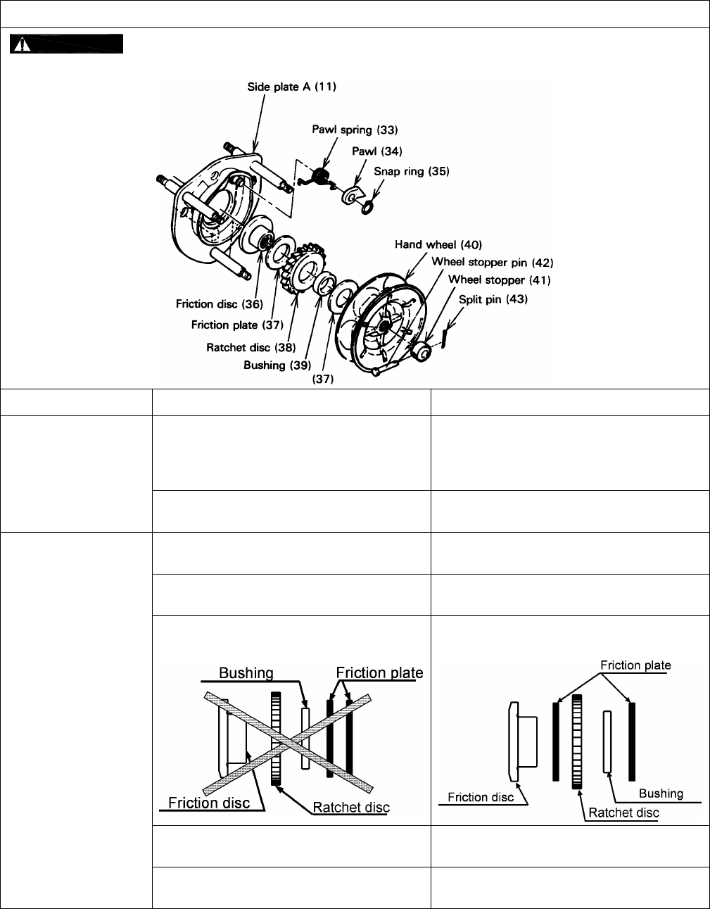
1) Orient a hoist with wheel cover side up.
2) Unscrew three nuts [45] (with the spring washers [46]) fixing the wheel cover [44] and remove the
wheel cover from the side plate A [11].
3) Remove the hand chain [48] from the hand wheel [40].
4) Pull out the split pin [43] from the wheel stopper pin [42] and remove the wheel stopper pin and the
wheel stopper [41] from the pinion [17].
*NOTE: If the hoist has an over load limiter, instead of step 4, remove the left hand threaded nut from
the pinion.
5) Remove the hand wheel [40] from the pinion [17] by turning the hand wheel counterclockwise.
*NOTE: If the hand wheel is too tight to turn by hand, put the hand chain back on the hand wheel and
pull it down hard. It will release the brake.
6) Remove two friction plates [37], the ratchet disc [38] and the bushing [39] from the friction disc [36].
7) Unscrew the friction disc [36] from the pinion [17] by turning counterclockwise holding the end of
the pinion with your fingers.
8) Remove the snap ring [35] from the pawl pin (on the side plate A) and then remove the pawl [34]
and pawl spring A [33] and B [33].
28
9) For 8 ton capacity and under:
Pull the split pin [24] out from the stopper pin [23] and remove the load chain [47] and the stopper
pin from the stopper [22].
10) For 10 ton capacity and above:
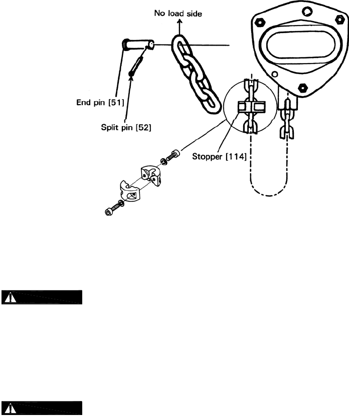
Pull the split pin [52] out from the end pin [51] and remove the load chain [47] and the end pin.
Unscrew two socket bolts (with the spring washers) fixing the stoppers [114] and remove the
stoppers.
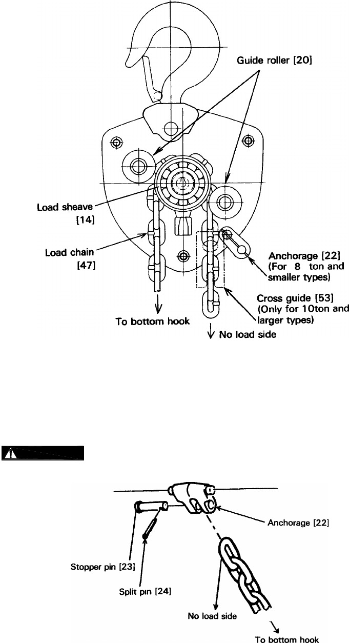
11) Remove the load chain [47] from the load sheave [14] by pulling the load chain toward the bottom
hook.
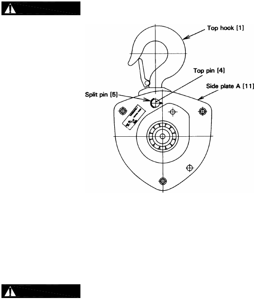
12) Remove the split pin [5] from the top pin [4], then remove the top pin and the top hook [1] from the
side Plate A [11] and B [13].
13) Place hoist with gear case side (or nameplate side) up.
14) Unscrew three nuts [31] (with the spring washers [32]) fixing the gear case [29], remove the gear
case from the side plate B [13], and remove the ball bearing [28] from the gear case.
15) Remove two pairs of the gear #2 [27] (1/2T has one pair) from the side plate B [13].
16) Remove the snap ring [26] from the load sheave [14], then the load gear [25] from the load
sheave.
17) Remove the side plate B [13] from the side plate A [11] and then take the ball bearing [16] out
from the side plate B.
18) Remove the guide rollers [20], load sheave (attached to the pinion [17]), stripper [21] and the
anchorage (stopper) [22] (for 10 Ton capacity and above: cross guide [53]) from the side plate A
[11], then remove the ball bearing [15] from the side plate A.
19) Remove the snap ring [19] in the load sheave [14].
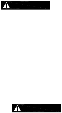
20) Remove the pinion [17] and the roller bearing [18] from the load sheave [14].
*NOTE: Hold the load sheave by hand and remove the bearing by tapping the pinion with a rubber
mallet.
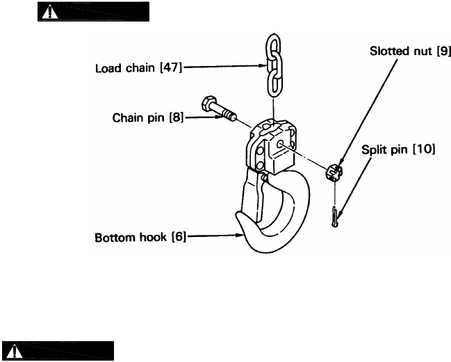
21) Pull the split pin [10] out from the slotted nut [9] and remove the slotted nut and chain pin from the
bottom hook [6].
6.4 Hoist Assembly
6.4.1
Inspect and replace any worn or damaged parts per Table 5-3.
Secure all nuts, bolts and split pins firmly.
Replace all split pins and retaining rings.
6.4.2 Assembly
1) Apply grease to the rollers of the roller bearing [18] and insert the pinion [17] (from the side of the
brake screw) into the roller bearing and insert them together into the load sheave [14]. Fix them
with a snap ring [19].
*NOTE: The arrow* on the outer side of the roller bearing should face the gear side. When
inserting, use a screwdriver on the bearing and tap it with a rubber mallet. See Fig. 6-1.
: Always make sure that the snap ring is correctly seated.
29
Figure 6-1 Load Sheave/Pinion Assembly
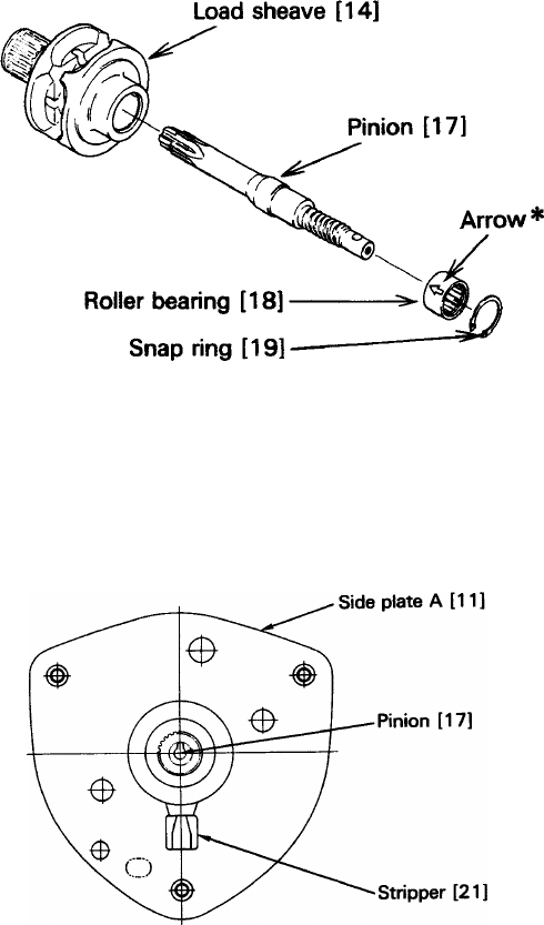
2) Grease the balls of the ball bearing [15]. Orient side plate A [11] with brake cover side down and
insert the ball bearing [15] (with a snap ring side up) into the side A.
3) Insert the load sheave [14] with a part of spline side (pinion gear side) up into the ball bearing [15].
The stripper [21] must be inserted as well. See Figure 6-2.
Figure 6-2 Side Plate / Load Sheave Assembly
4) For 8 ton capacity and below:
Put the guide rollers [20] and the anchorage (stopper) [22] in the side plate A [11].
For 10 ton and larger capacities:
Put the guide rollers [20] and the cross guide [53] in the side plate A [11].
*NOTE: Put the cross guide so that the longer are fits to the side plate A.
5) Grease the balls of the ball bearing [16]. Insert it with the snap ring side down to the shaft of the
load sheave [14]. See figure 6-3.
*NOTE: Make sure the snap ring side of the ball bearing is oriented toward the load sheave.
30
Figure 6-3 Side Plate Assembly
6) Join the side plate B [13] to the side plate A [11].
*NOTE: In case it is difficult to join the two, tap it with a rubber mallet. Be careful not to let the
stripper, guide roller or stopper fall down.
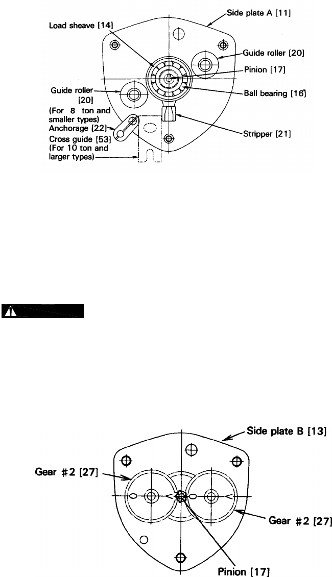
7) Mesh the load gear [25] with the splines of the load sheave [14] and fix it with a snap ring [26].
: Always make sure the snap ring is completely seated at the bottom of the
groove.
8) Grease the two pairs of the gear #2 [27], the load gear [25], and the gear of the pinion [17]. Put
them in the gear plain bearing (bearing A) of the side plate B [13]. Letters “O” and “V” on the gears
must face each other as shown in figure 6-4 below. Do not forget to apply grease to the boss on
the both sides of the gear #2.
*NOTE: It is not necessary to adjust the letters in case of the 1/2T model, for it has only one pair of
the gear #2.
Figure 6-4 Gear Train Assembly
9) Grease the balls of the ball bearing [28] and insert it with the snap ring down into the end of the
pinion [17] shaft.
10) Join the gear case [29] to the side plate A [11] and fix them with the three spring washers [32] and
nuts [31].
31
11) Place the top hook [1] between side plates A [11] and B [13]. Then insert top pin [4] and fix it with
the split pin [5].
: Always bend the split pin securely after inserting it into the top pin.
Figure 6-5 Gear Train Assembly
12) Place the hand wheel [40] side upward.
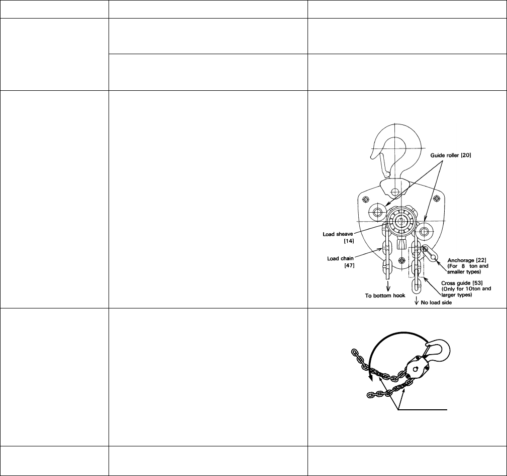
13) Reeve the load chain [47] turning the pinion clockwise through the space between the left (bottom
hook side) guide roller [20] and the load sheave [14]. See figure 6-6.
: Put the welded part of the vertical chain link outward and reeve it through the
load sheave. Pull it out between the right guide roller (no load side) and the load sheave.
For 10 ton capacities and above, pass the no load end of the chain through the cross guide [53].
*NOTE: It is recommended for this process to position the unit so that the side plate A [11] faces left
and the side plate B [13] faces right.
32
Figure 6-6 Reeving Assembly
14) For 8 ton capacity and below:
Pull the end of the load chain [47] out between the right guide roller [20] and the load sheave [14]
(no load side) and insert it to the anchorage (stopper) [22]. Insert the stopper pin [23] and fix it with
a split pin [24].
: Make sure the load chain is not twisted and the split pin in the stopper pin is bent
securely.
Figure 6-7 8 Ton & Below Anchorage Assembly
33
For 10 ton capacity and above:
Connect the no load end of the load chain [47] to the end pin [51] which is to be inserted from gear
case [29] side. Use a split pin [52] to secure the end pin. Assemble stoppers [114] to the ninth link
from the no load end of the load chain by socket bolts and spring washers.
*NOTE: Threaded hole of one stopper shall face to non-threaded hole of the other stopper.
Socket bolt shall be inserted from the non-threaded side.
Figure 6-8 10 Ton & Above Anchorage Assembly
15) Apply machine oil to the pawl pin (in side plate A [11]) and join the pawl spring A [33], and B [33]
and the pawl [34] respectively to it. Fix them with a snap ring [35]. See figure 6-9.
: Make sure the pawl spring is touching the pawl and the snap ring is completely
seated at the bottom of the groove.
16) Attach the friction disc [36] to the pinion [17] shaft (while turning the pawl [34] counterclockwise).
17) Wipe out any dirt on the friction disc [36], friction plates [37] and both sides of the ratchet disc [38]
and check if the oil of the bushing [39] (bushing with oil in it) is adequate. Then place the friction
plate, bushing, ratchet disc and friction plate respectively on the friction disc. (Make sure that the
ratchet disc and the pawl mesh properly). See figure 6-9.
: Since the brake is a “dry system”, NEVER apply oil. Wipe out thoroughly any oil
and dirt on the brake. The gear of the ratchet disc should point at the pawl. Otherwise, the hand wheel
cannot be assembled later. In case the bushing does not have oil inside, soak it in turbine oil for a day.
Install it without wiping the oil.
34
Figure 6-9 Pawl & Brake Assembly
18) Wipe out any dirt on the brake surface of the hand wheel [40] and apply machine oil to the
threaded part of it. Screw it on the pinion [17] shaft all the way down.
19) Place the wheel stopper [41] on the head of the pinion [17], insert the wheel stopper pin [42] and
fix it with a split pin [43].
: Never forget to bend the split pin after inserting into the wheel stopper pin.
20) Put the hand chain [48] around the hand wheel [40]. See figure 6-10.
Figure 6-10 Hand Wheel Assembly
35
21) Assemble the wheel cover [44] to the side plate A [11] and fix them with the spring washer [46]
and the nut [45].
22) Insert the other end of the load chain [47] to the bottom hook [6] and fix them with the chain pin
[8], slotted nut [9] and split pin [10]. See figure 6-11.
: Always bend the split pin securely.
Figure 6-11 Bottom Hook Assembly
6.5 Storage
6.5.1
: IMPROPER chain hoist use could result in death or serious injury. To avoid these
hazards:
ALWAYS store the hoist in a no load condition.
ALWAYS wipe off all dirt and water.
ALWAYS oil the chain, hook pins and hook latches.
ALWAYS hang in a dry place.
ALWAYS check the hoist for abnormalities (according to the regular inspection procedures) when
using the hoist after a period of non-use (Refer to section 5.5).
6.6 Outdoor Installation
6.6.1 For hoist installations that are outdoors, the hoist should be covered or brought inside when not in use.
6.6.2 Possibility of corrosion on components of the hoist increases for installations where salt air and high
humidity are present. Make frequent and regular inspections of the hoist’s condition and operation
36
7.0 Troubleshooting
Read and comply with instructions in this manual and use the hoist properly.
Checking the sounds from the hoist in operation is a critical inspection. Note hoist sounds during operation.
If a defect is found in the hoist, stop using it immediately and check the cause of the defect.
Only Trained and competent personnel should inspect and repair the hoist.
Table 7-1 Troubleshooting Guide
Note on proper operation:
When lifting, the hoist should make clicking sounds when moving the hand wheel.
When lowering, the hoist should not make clicking sounds when moving the hand wheel.
Symptom Cause Remedy
Hoist will not lift –
Slight clicking
Improper assembly of ratchet disc, disc
installed backwards, and making incorrect
contact with the pawl.
Reassemble the pawl and ratchet disc
properly. Ensure that clicking sounds are
heard before reuse.
Hoist will not lift –
Not Clicking
Pawl not engaging ratchet disc:
Dirt or corrosion between pawl and pawl
shaft.
Clean and lubricate pawl and pawl shaft.
Pawl shaft
Pawl
Faulty pawl spring Replace pawl spring
Loose selector pawl spring Perform hoist maintenance.
Hoist will not lift –
Hand wheel will not
operate
Gear #2 improperly timed
Reassemble gears properly and ensure
smooth operation before reuse.
Ensure the ‘0’ & “V”
marks of gear #2 are aligned properly, as
shown.
37
Symptom Cause Remedy
Hoist will lift
intermittently –
Slight or irregular
clicking
Poor pawl movement caused by faulty pawl
spring. The spring is loose or damaged. Perform maintenance and/or repair.
Mis-assembly of pawl spring Reassemble it properly and ensure to check
click sound of the pawl before reuse.
During operation, hoist
idles or load drifts
Poor contact of load sheave and load chain
caused by improper chain-reeving.
Reassemble properly and ensure proper
lifting before reuse.
Hoist will not lift all the
way (multiple fall
hoists) Capsized hook
Reset the capsized hook.
Twisted Chain
Capsized Hook and Chain
Double Fall Models
Hoist does not lift load
smoothly. Improper assembly of gear OR bearing
broken. Disassemble and reassemble gear train
and/or replace bearing.
38
Table 7-1 Troubleshooting Guide
Improper braking may cause improper load lowering. The hoist utilizes dry friction discs; do not
apply oil to friction surfaces.
Symptom Cause Remedy
Load will not go down
Over tightened brake
The hoist left under load for a long period
Shock loaded during operation
Pull down hard (possibly with 2 people) on
the hand chain to loosen brake.
Brake rusted tight Replace the rusty components and perform
hoist maintenance.
Load drifts or slips
when lowering
A foreign object between friction surfaces. Remove the object and clean the surfaces.
Replace if the friction surface is scarred.
Brake slip caused by significant rust Replace the rusty component and perform
hoist maintenance.
Mis-assembly of friction plates, i.e. friction
plates missing or at one side as shown.
Reassemble properly as shown and ensure
hoist functions properly before reuse.
Cracked friction plate caused by overload Replace the friction plate and use the hoist
properly within rated capacity.
Friction plate wear caused by very frequent
and long term use. Perform hoist maintenance.

39
8.0 Warranty
All products sold by Harrington Hoists, Inc. are warranted to be free from defects in material and
workmanship from date of shipment by Harrington for the following periods:
Manual Hoists, Trolleys, & Beam Clamps - 2 years
NER/ER Hoists Enhanced Features Models – 3 years
Electric Hoists, Air Hoists & Trolleys, Crane Components - 1 year
Spare / Replacement Parts - 1 year
NER/ER “The Guardian” Electromagnetic Smart Technology Brake – 10 years
The product must be used in accordance with manufacturer’s recommendations and must not have
been subject to abuse, lack of maintenance, misuse, negligence, or unauthorized repairs or
alterations.
Should any defect in material or workmanship occur during the above time period in any product,
as determined by Harrington Hoist’s inspection of the product, Harrington Hoists, Inc. agrees, at its
discretion, either to replace (not including installation) or repair the part or product free of charge
and deliver said item F.O.B. Harrington Hoists, Inc. place of business to customer.
Customer must obtain a Return Goods Authorization as directed by Harrington or Harrington’s
published repair center prior to shipping product for warranty evaluation. An explanation of the
complaint must accompany the product. Product must be returned freight prepaid. Upon repair,
the product will be covered for the remainder of the original warranty period. Replacement parts
installed after the original warranty period will only be eligible for replacement (not including
installation) for a period of one year from the installation date. If it is determined there is no defect,
or that the defect resulted from causes not within the scope of Harrington’s warranty, the customer
will be responsible for the costs of returning the product.
Harrington Hoists, Inc. disclaims any and all other warranties of any kind expressed or implied as to
the product’s merchantability or fitness for a particular application. Harrington will not be liable for
death, injuries to persons or property or for incidental, contingent, special or consequential
damages, loss or expense arising in connection with the use or inability whatever, regardless of
whether damage, loss or expense results from any act or failure to act by Harrington, whether
negligent or willful, or from any other reason

40
This Page Intentionally Left Blank
41
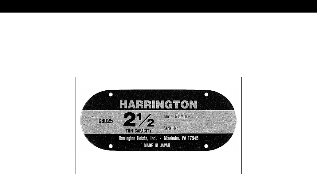
9.0 Parts List
When ordering Parts, please provide the Hoist model number, lot number, and serial number located on the Hoist
nameplate (see Figure 9-1 below).
Reminder: Per Sections 1.1 and 3.4.4 to aid in ordering parts and product support, record the hoist Code, Lot and Serial
Number in the space provided on the cover of this manual.
Figure 9-1 - M3CB Nameplate
The parts list is arranged into the following sections:
Section Page
9.1 1/2 to 20 Ton Parts………………….…………………………………………………...……….……...42
9.2 3 to 20 Ton Parts………………….…………………………………………………...……….……......46
9.3 CB Slip Clutch Device………………………………………………………………….….…….……… 50
9.4 Optional Hooks……………………..……………….………………………………….….…….……… 51
9.5 Optional Chain Containers…………………………………………………………….….…….……… 53
42
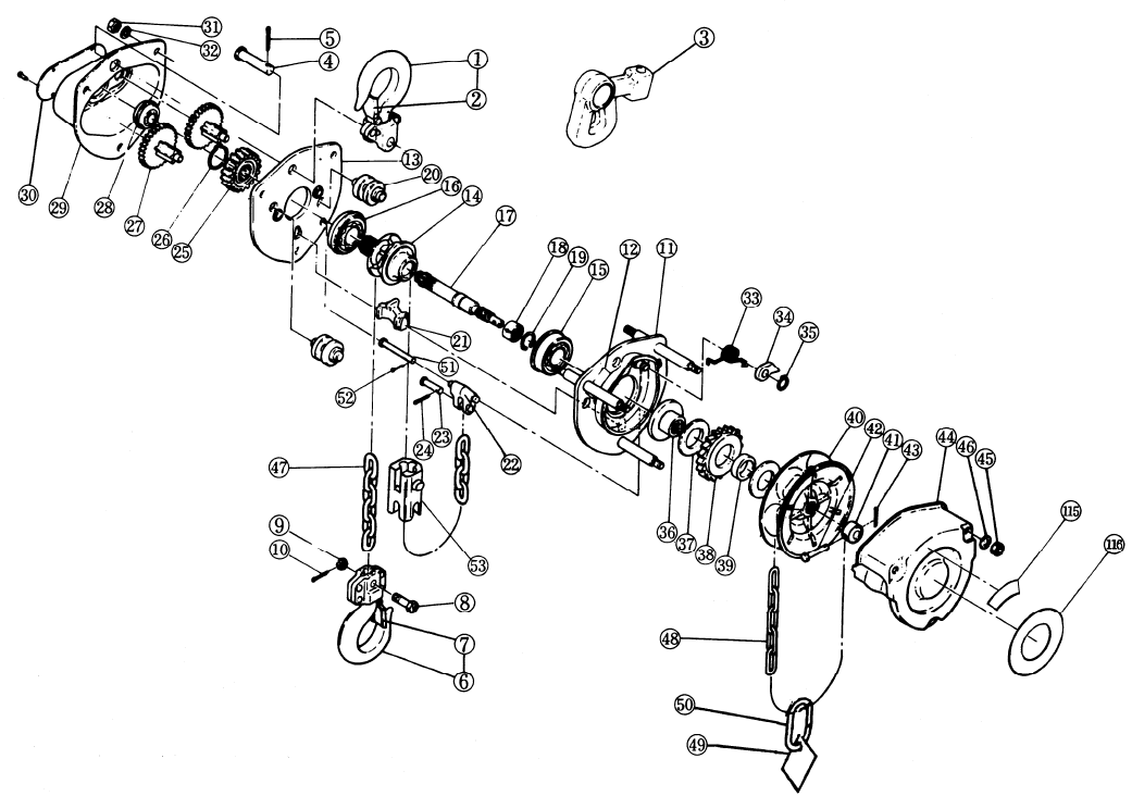
9.1 1/2 to 20 Ton Parts
Figure 9-2 – ½ to 20 Ton Parts

43
9.1 1/2 to 20 Ton Parts
Fig.
No. Part Name
Qty
per
Hoist
Capacity (T)
1/2 1 1½ & 3 2 2½ - 5 - 8 10 - 15 - 20
*1 Top Hook Set 1 CF001005 CF001010 *CF001015 M3001A020 *M3001A025
*2 Latch Assembly 1 CF071005 CF071010 *CF071015 CF071020 CF071050
*3 Suspender G 1 M3003010
Suspender 1 M3004015 M3004020 M3004025
4 Top Pin 1 M3163005 M3163010 M3163015 M3163020 M3163025
5 Split Pin 1 9009423 9009424
*6 Bottom Hook Set 1 M3021A005 M3021A010 *M3021A015 M3021A020 *M3021A025
*7 Latch Assembly 1 CF071005 CF071010 *CF071015 CF071020 *CF071030
*8 Chain Pin 1 M3041005 M3041010 *M3041015 M3041020 *M3041025
*9 Slotted Nut 1 M3049005 M2049010 *M2049010 *M2049020
*10 Split Pin 1 9009402 *9009411 *9009412
11
Side Plate A Ass’y 1 M3101005 M3101010 M3101015 M3101020 M3101025
Side Plate A Ass’y
(M3B Model) 1 M3B101025
12 Nameplate F 1 C3BA0059806
13
Side Plate B Ass’y 1 M3102005 M3102010 M3102015 M3102020 M3102025
Side Plate B Ass’y
(M3B Model) 1 M3B102025
14 Load Sheave 1 M3116005 M3116010 M3116015 M3116020 M3116025
15 Ball Bearing 1 M3140005 M3140020
16 Ball Bearing 1 M3145005 M3140005 M3140020
17
Pinion 1 M3111005 M3111010 M3111015 M3111020 M3111025
Pinion
(M3B Model) 1 M3B111025
18 Roller Bearing 1 M3130005 M3130020
19 Snap Ring 1 M3118005 M3118020
20 Guide Roller 2 M3161005 M3161010 M3161015 M3161020 M3161025
21 Stripper 1 M3162005 M3162010 M3162015 M3162020 M3162025
22 Anchorage 1 M3176005 M3176010 M3176015 M3176020 M3176025
23 Stopper Pin 1 M3177005 M3177010 M3177015 M3177020 M3177025
24 Split Pin 1 9009412 9009415-5
25 Load Gear 1 M3114005 M3114010 M3114015 M3114020 M3114025
26 Snap Ring 1 9047123 9047128 9047132
27
Gear No. 2 Ass’y 1 M3112005
2
M3112010 M3112015 M3112020 M3112025
Gear No. 2 Ass’y
(M3B Model) M3B112025
28 Ball Bearing 1 M3135005 M3135020
29 Gear Case Ass’y 1 M3103005 M3103010 M3103015 M3103020 M3103025
30
Nameplate B w/
Rivets
1
M3800005 M3800010 *M3800015 M3800020
Nameplate B w/
Rivets (M3B
Model)
*M3800025
31 Nut 3 9093424 9093427 9093433
*Part number applies to 1½ or 2½ Ton capacities only. See additional parts list for 3, 5, and 8 Ton capacities.

44
9.1 1/2 to 20 Ton Parts
Fig.
No. Part Name
Qty
per
Hoist
Capacity (T)
1/2 1 1½ & 3 2 2½ - 5 - 8 10 - 15 - 20
32 Spring Washer 3 9012711 9012712 9012713
33 Pawl Springs
Assembly 1 C3BA0055179
34 Pawl 1 M3155005
35 Snap Ring 1 9047110
36
Friction Disc
1
M3153005 M3153020
Friction Disc
(M3B Model) M3B153025
37
Friction Plate
2
M3151005 M3151020
Friction Plate
(M3B Model) M3B151025
38
Ratchet Disc
1
M3152005 M3152020
Ratchet Disc
(M3B Model) M3B152025
39
Bushing
1
M3154005 M3154020
Bushing (M3B
Model) M3B154025
40
Hand Wheel
1
M3115005 M3115015 M3115020 M3115025
Hand Wheel
(M3B Model) M3B115025
41 Wheel Stopper 1 CF159005 CF159010
42 Wheel Stopper
Pin 1 M2167005
43 Split Pin 1 9009410
44 Wheel Cover
Ass’y 1 M3171005 M3171015 M3171020 M3171025
45 Nut 3 9093424
46 Spring Washer 3 9012711
47 Load Chain 1@ ft. LCCF005 LCCF010 LCCF015 LCC3020 LCC3025
48 Hand Chain 1@ ft. HCCF005
49 Warning Tag 1 WTAG9
50 Chain Stopper
Link 1 L4045030
115 Slip Clutch Label 1 C3YU0059802 C3YU0209802
116 Harrington Label 1 M3700005 M3700015 M3700020 M3700025
*Part number applies to 1½ or 2½ Ton capacities only. See additional parts list for 3, 5, and 8 Ton capacities.

45
This Page Intentionally Left Blank
46
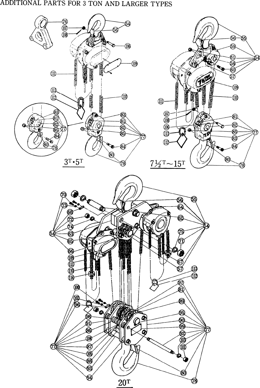
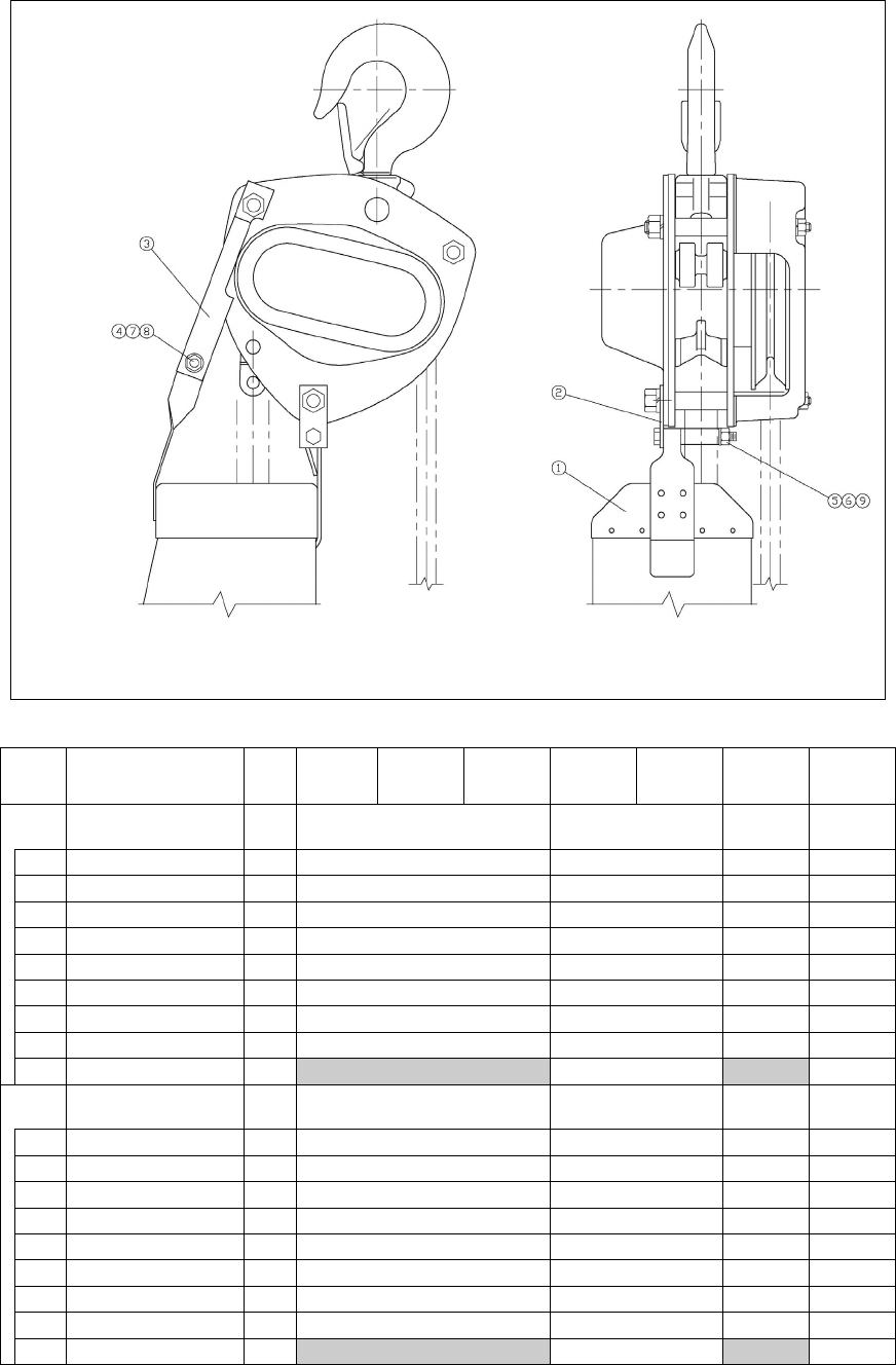
9.2 3 to 20 Ton Parts
Figure 9-3 - 3 to 20 Ton Parts

47
9.2 3 to 20 Ton Parts
Fig.
No. Part Name
Qty
per
Hoist
Capacity (T)
3 5 8 10 15 20
51 End Pin 1 M3B164100
52 Split Pin 1 9009415-5
53 Cross Guide 1 M3B176100
54 Top Hook Set 1 M3001A030 M3001A050 M3001A075 M3001A100 M3001A150
2 M3001A200
55 Top Hook 1 M3001150 M3001200
Top Hook Ass’y 1 L42001090
56 Latch Assembly 1 CF071030 M3072050 L41071090 M3072150 M3072200
57 Idle Sheave
Ass’y
1 M3051050
2 M31051150
3 M31051150
58 Shaft Assembly 1 M3053050
59A Top Yoke A 1 M3011075 M3011100 M3016150
59B Top Yoke B 1 M3012075 M3012100 M3017150
60 Socket Bolt 3 90912116
1 90912116
61 Lever Nut 3 L4082090
1 L4082090
- Socket Bolt 2 M3086100
- U-Nut 2 9098516
62 Top Susp. Shaft 2 M3010150 M3010200
63 Top Yoke 2 M3011200
64 Top Plate A
Assembly
1 M35012150
2 M35012200
- Top Plate B 1 M3014150
65 Guide 4 M3018150
6 M3018150
66 Stay Bolt 2 M3019150 M3019200
- Top Plate 1 M3043150
67 Top Shaft 1 M3053150 M3053200
68 Key Plate 2 M2056150
- Collar 2 M3066150
70 Socket Bolt 4 9091270
71 Nut 4 9093458
72 Nut 4 9093445
73 Spring Washer 4 9012711
74 Spring Washer 4 9012717
75 Spring Washer 4 9012721

48
9.2 3 to 20 Ton Parts
Fig.
No. Part Name
Qty
per
Hoist
Capacity (T)
3 5 8 10 15 20
77 Bottom Hook
Set 1 M3021A030 M3021A050 M3021A075 M3021A100 M3021A150 M3021A200
78
Bottom Hook 1 M3021150 M3021200
Bottom Hook
Assembly 1 M3021030 M3021050 L42001090
80 Latch Assembly 1 CF071030 M3072050 L41071090 M3072150 M3072200
81 Idle Sheave
Assembly
1 CF051030 M3051050
2 M3051050
3 M31051150
4 M31051150
82
Shaft Assembly 1 CF053030 M3053050
Bottom Shaft
Assembly 1 M3054100
83 Bottom Yoke
Assembly 1 M3031030 M3031050 M3031075 M3031100
84 Socket Bolt 2 9091296 90912116 M3088100
3 9091296
85 Lever Nut 2 L4082060 L4082090
3 L4082060
U-Nut 2 9098516
86 Guide 6 M3018150
8 M3018150
87 Hook Support 2 M3026150 M3026200
88 Bottom Yoke 1 M3030150 M3030200
89 Bottom Plate A 1 M3034150
2 M3034200
90 Bottom Plate B 1 M3035150 M3035200
91 Bottom Plate C 1 M3036200
92 Stay Bolt 4 M3038150 M3038200
93 Collar A 2 M3039200
94 Collar B 4 M3040200
95 Bottom Shaft 1 M3054150 M3054200
96 Key Plate 2 M2056150
97 Washer A 2 M3058200
98 Collar 4 M3066200
99 Nameplate A w/
Rivets 1 M3069150 M3069200
100 Socket Bolt 4 9091270
101 Nut 8 9093445
102 Spring Washer 4 9012711
103 Spring Washer 8 9012717
104 Tongued
Washer 4 M3091150
105 Bolt 4 9093350

49
9.2 3 to 20 Ton Parts
Fig.
No. Part Name
Qty
per
Hoist
Capacity (T)
3 5 8 10 15 20
106 Chain Pin 1 M3041030 M3041075
107 Slotted Nut 1 M2049010 M2049020
108 Split Pin 1 9009411 9009412
109
Nameplate B w/
Rivets 1 M3800030 M3800080 M3800030
Nameplate B w/
Rivets (M3B
Model)
1 M3800050 M3B800100 M3B800150
2 M3B800200
110 Load Chain 1@ ft. LCCF015 LCC3025
111 Hand Chain 1@ ft. HCCF005
2@ ft. HCCF005
112 Warning Tag 1 WTAG9
2 WTAG9
113 Chain Stopper
Link
1 L4045030
2 L4045030
114 Stopper
Assembly
1 M3045100
2 M3045100
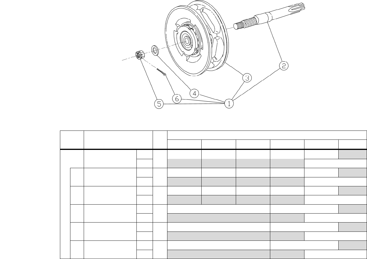
Figure 9-4 Slip Clutch
FIG NO. PART NAME QTY
CAPACITY
1/2 T 1 T 1 1/2 & 3 T 2 T 2 1/2-5 T 8-10-15-20 T*
1 OLL ASSEMBLY
M3
1
M3CB005OD M3CB010OD M3CB015OD M3CB020OD M3CB025OD
M3B M3B025OD
2 PINION
M3
1
C3YA111005 C3YA111010 C3YA111015 C3YA111020 C3YA111025
M3B C3BYA111025
3 HAND WHEEL
M3
1
C3YA1115005 C3YA1115010 C3YA1115015 C3YA1115020 C3YA1115025
M3B C3BYA1115025
4 WASHER
M3
1
C3YA208005 C3YA208020
M3B C3YA208020
5 NUT (left hand thread)
M3
1
C3YA209005 C3YA209020
M3B C3YA209020
6 Split Pin
M3
1
9009415 9009417
M3B 9009417
*20 Ton capacity requires Quantities of 2.
9.3 CB Slip Clutch Device
50
51
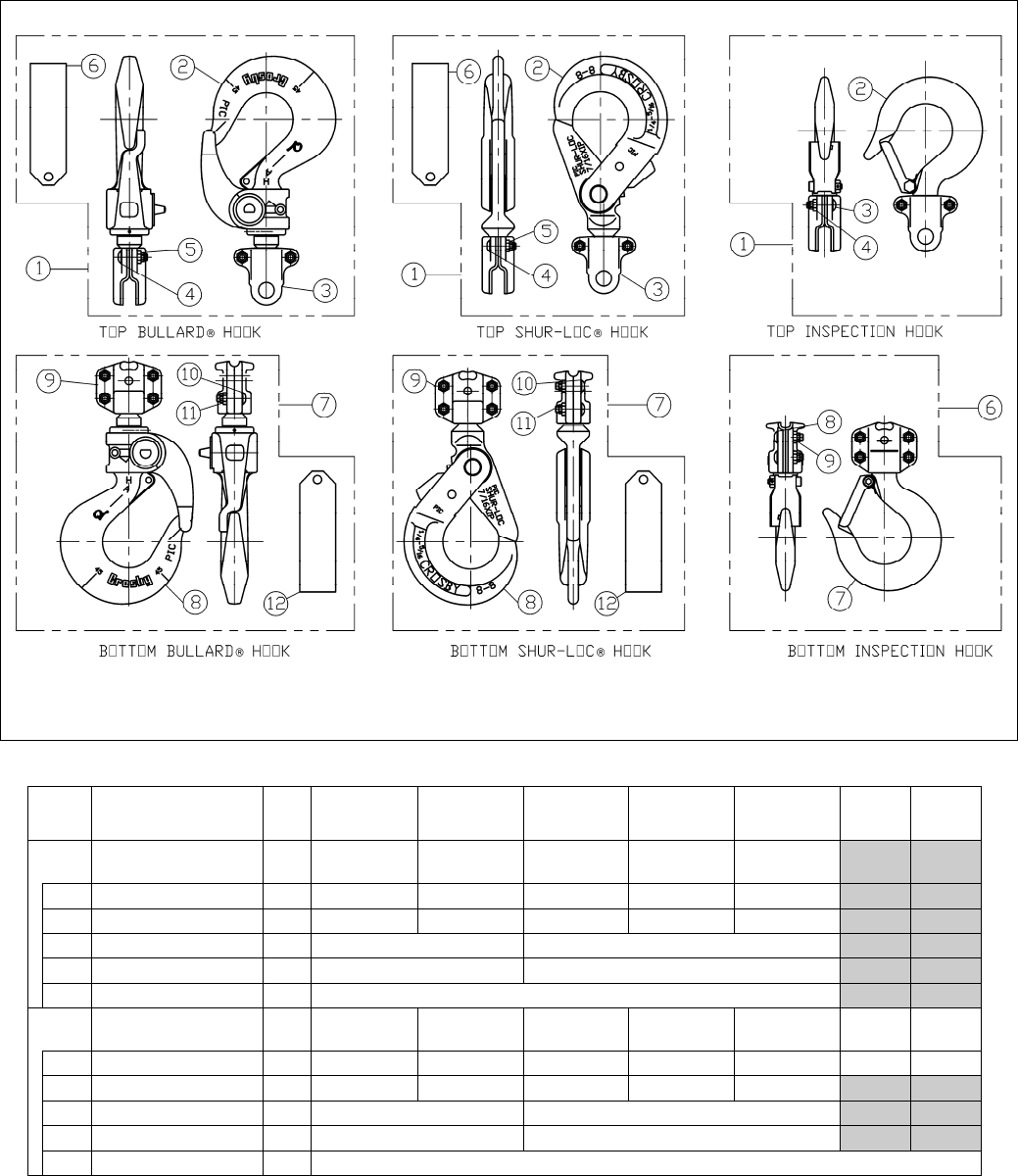
9.4 Optional Hooks
Figure 9-5 Bullard®, Shur-Loc® and Inspection Hooks
Bullard® Hooks
Fig. No. Name
Parts
Per
Hoist
½ T 1T 1½T 2T 2½T 3T 5T
1 Bullard® Top Hook
Complete Set 1 6027601 6027602 6027603 6027604 6027605
2 Bullard® Hook Assembly 1 60160 60162 60164 60165 60166
3 Top Yoke Kit 1 TYKITCB005 TYKITCB010 TYKITCB015 TYKITCB020 TYKITCB025
4 Button Head Screw 2 9012601 9012602
5 Flexloc® Nut 2 9012603 9012604
6 Warning Tag 1 WTAG6*
7 Bullard® Bottom Hook
Complete Set 1 6027801 6027802 6027803 6027804 6027806 6027807 6027808
8 Bullard® Hook Assembly 1 60160 60162 60164 60165 60166 60168 60169
9 Bottom Yoke Kit 1 BYKITCB005 BYKITCB010 BYKITCB015 BYKITCB020 BYKITCB025
10 Button Head Screw 4 9012601 9012602
11 Flexloc® Nut 4 9012603 9012604
12 Warning Tag* 1 WTAG6*
*Hoist with Bullard® Hook(s) must have WTAG6 and WTAG9 installed. (See page 6 for WTAG9).

52
9.4 Optional Hooks
Shur-Loc® Hooks
Fig. No. Name
Parts
Per
Hoist
½T 1T 1½T 2T 2½T
1 Shur-Loc® Top Hook
Complete Set 1 6030201 6030202 6030203 6030204 6030205
2
Shur-Loc® Hook
Assembly 1 60140 60142 60144 60145 60146
3 Top Yoke Kit 1 TYKITCB005 TYKITCB010 TYKITCB015 TYKITCB020 TYKITCB025
4 Button Head Screw 2 9012601 9012602
5 Flexloc® Nut 2 9012603 9012604
6 Warning Tag 1 WTAG6*
7 Shur-Loc® Bottom Hook
Complete Set 1 6030101 6030102 6030103 6030104 6030106
8
Shur-Loc® Hook
Assembly 1 60140 60142 60144 60145 60146
9 Bottom Yoke Kit 1 BYKITCB005 BYKITCB010 BYKITCB015 BYKITCB020 BYKITCB025
10 Button Head Screw 4 9012601 9012602
11 Flexloc® Nut 4 9012603 9012604
12 Warning Tag 1 WTAG6*
*Hoist with Shur-Loc® Hook(s) must have WTAG6 and WTAG9 installed. (See page 6 for WTAG9).
Inspection Hooks
Fig. No. Name
Parts
Per
Hoist
½ T 1T 1½T 2T 2½T
1 Top Hook Complete
Set 1 M3001A005IK M3001A010IK M3001A015IK M3001A020IK M3001A025IK
2 Hook W/Latch & Yoke 1 M3001A005IH M3001A010IH M3001A015IH M3001A020IH M3001A025IH
3 Button Head Screw 2 9012601 9012602
4 Flexloc® Nut 2 9012603 9012604
6 Bottom Hook Complete
Set 1 M3021A005IK M3021A010IK M3021A015IK M3021A020IK M3021A025IK
7 Hook W/Latch & Yoke 1 M3021A005IH M3021A010IH M3021A015IH M3021A020IH M3021A025IH
8 Button Head Screw 2 9012601 9012602
9 Flexloc® Nut 2 9012603 9012604
53
9.5 Optional Chain Containers
Figure 9-6 M3CB Optional Chain Container
CF4 OPTIONAL CHAIN CONTAINERS
Fig. No. Name
Parts
Per
Hoist
½T 1T 1½T 2T 2½T 3T 5T
“05” Chain Container
(BKC1) Assembly 1 60461 60463 60461 60463
1 Chain Container 1 50545 50545 50545 50545
2 Front Hanger Ass’y 1 5048305 5048305 5048305 5048305
3 Back Hanger 1 5048304 50940 5048304 50940
4 Washer 2 9012513 9012513 9012513 9012513
5 Nut 1 9093424 9093424 9093424 9093424
6 Lock Washer 1 9005310 9005310 9005310 9005310
7 Hex Head Bolt 1 9093327 9093327 9093327 9093327
8 Lock-Nut 1 9098506 9098506 9098506 9098506
9 Spacer 1 5048301 5048301
“10” Chain Container
(BKD1) Assembly 1 60462 60464 60462 60464
1 Chain Container 1 30090 30090 30090 30090
2 Front Hanger Ass’y 1 5048305 5048305 5048305 5048305
3 Back Hanger 1 5048304 50940 5048304 50940
4 Washer 2 9012513 9012513 9012513 9012513
5 Nut 1 9093424 9093424 9093424 9093424
6 Lock Washer 1 9005310 9005310 9005310 9005310
7 Hex Head Bolt 1 9093327 9093327 9093327 9093327
8 Lock-Nut 1 9098506 9098506 9098506 9098506
9 Spacer 1 5048301 5048301
54
NOTES
55
NOTES

www.harringtonhoists.com
Harrington Hoists, Inc. Harrington Hoists – Western Division
401 West End Avenue 2341 Pomona Rd. #103
Manheim, PA 17545-1703 Corona, CA 92880-6973
Phone: 717-665-2000 Phone: 951-279-7100
Toll Free: 800-233-3010 Toll Free: 800-317-7111
Fax: 717-665-2861 Fax: 951-279-7500
M3CBOM
