Harris Farinon Division 9GKAUR5802T1-1 AURORA 5800 Spread Spectrum Microwave Radio System User Manual
Harris Corporation Farinon Division AURORA 5800 Spread Spectrum Microwave Radio System
Users Manual

RMN-112862-E02
Issue 2, January 31, 2000
Reference
Aurora
TM
5800
5.8 GHz
Digital Radio
next level solutions

Copyright 2000, HARRIS CORPORATION. All rights reserved.
Aurora is a trademark of the HARRIS CORPORATION.
Microsoft, Windows, and Windows NT are registered trademarks of Microsoft Corporation.
HARRIS CORPORATION
Microwave Communications Division
350 Twin Dolphin Drive
Redwood Shores, CA 94065-1421
http://www.microwave.harris.com
We’re ISO certified.
Caveat
Spread spectrum point-to-point radio relay links like Aurora’s are allowed by various regulatory agencies to
operate unlicensed on a “noninterference basis”. Because of the unlicensed nature, the Aurora radios require
neither frequency licensing nor prior coordination in most regions. Good engineering judgment needs to be
exercised by the operator and professional installer to avoid selecting paths or locations near equipment or
facilities that could generate interfering signals. Such equipment might include microwave ovens and other
high-power ISM devices. Additionally, precaution should be taken when links are deployed in a region
where a large number of other 5.8-GHz, point-to-point or point-to-multipoint links are installed.
The Aurora installation software with its adjustable power feature is for professional installer use only, as
mandated by the Federal Communications Commission (FCC, Part 15) and the European
Telecommunications Standard Institute (ETS 300-328). The customer version is provided with the
adjustable power feature disengaged.
Harris Corporation does not assume any liability or damage arising out of the application or misuse of
this Aurora radio product and its software.
Warranty
Any warranties or conditions made herein by Harris are exclusive, made in lieu of all other warranties or
conditions, express or implied (except to title) including, but not limited to, any implied warranty or
condition of merchantability, any implied warranty or condition of fitness for a particular purpose, or any
warranty or condition arising out of performance or custom or usage of trade. Customer acknowledges any
circumstances causing any such exclusive or limited remedy to fail of its essential purpose shall not affect
any Harris warranty.
Aurora 5800 contains no user-serviceable or replaceable parts.
Limitation of Damages
Harris’ total and maximum liability under this agreement, or in connection with the subject matter of this
agreement, or any transaction related to this agreement, shall be limited to one-half (1/2) of the aggregate
amount paid to Harris, regardless of the basis for such liability. The customer acknowledges and agrees that
this section shall be enforceable in the event of any claim made in connection with this agreement, including,
but not limited to, any claim for failure of delivery. In no event shall Harris be liable for any punitive,
special, incidental, or consequential damages, including, but not limited to, lost profits, opportunities, or
savings, or for any loss of use of, or loss of data or information of any kind, however caused, or for any full
or partial loss of performance of any product, even if Harris has been advised of the possibility of such
damages.

Aurora 5800
1
•
•
•
•
•
•
• • • • • •
Contents
List of Figures . . . . . . . . . . . . . . . . . . . . . . . . . . . . 11
List of Tables . . . . . . . . . . . . . . . . . . . . . . . . . . . . . 15
Customer Support. . . . . . . . . . . . . . . . . . . . . . . . . 19
Caveat .............................................................................. 19
Repair and Return .......................................................... 19
Service Center Locations .............................................. 20
U.S.A. ...................................................................................... 20
Canada .................................................................................... 20
Telephone and Fax Numbers ................................................. 20
Technical Support .......................................................... 21
Customer Resource Center ..................................................... 21
Business Hours ....................................................................... 21
Telephone Numbers ................................................................ 21
Fax Number ............................................................................. 21
Internet .................................................................................... 22
Customer Training .......................................................... 22
Telephone Number .................................................................. 22
Training Centers ...................................................................... 22
Canada .............................................................................. 22
U.S.A. ................................................................................ 22

2 Contents
•
•
•
•
•
•
CHAPTER 1, Introduction .......................................................... 23
Aurora 5800 Overview .................................................... 23
Related Publications ...................................................... 24
CHAPTER 2, Product Description ............................................ 25
Physical Description ...................................................... 25
Front View ............................................................................... 25
Back View ................................................................................ 27
DC Connector .......................................................................... 27
T1/E1 Line Interface ....................................................... 28
T1/E1 Interface Connector ...................................................... 28
Unbalanced E1 Interface ......................................................... 28
Alarm Port ................................................................................ 29
CIT Port ................................................................................... 30
DATA Port ............................................................................... 30
PHONE .................................................................................... 31
Hardware Assemblies .................................................... 32
Modem ..................................................................................... 32
Transmit Direction ............................................................. 32
Receive Direction .............................................................. 34
Jumper Settings ................................................................ 36
DIP Switch Settings ........................................................... 38
Upconverter and Power Amplifier ............................................ 39
Down Converter and Low-Noise Amplifier ............................... 39
Nominal Frequencies ............................................................... 40
Antenna Diplexer ..................................................................... 40
Aurora 5800 Block Diagram .................................................... 40
CHAPTER 3, System Description ............................................. 43
Frequency Plans ............................................................. 43
Coexistence with Other Radio Links ........................................ 43
Aurora Frequency Plan ............................................................ 43

Aurora 5800
3
•
•
•
•
•
•
Spread Sequence Pseudo-random Number (PN) Selection ... 44
Aurora 5800 Radio Configurations ............................... 45
Point-to-Point Configuration .................................................... 45
Repeater Configuration ........................................................... 46
Multihop and Hubbing Arrangements .......................... 48
Network Planning .................................................................... 48
Parallel-Path Arrangement for Higher Capacity or Protection . 49
Multihop Networking Arrangement through Repeaters ............ 49
Hubbing (Star) Networking Arrangement Out of a Node ......... 50
Wanted and Unwanted Signal Path Antennas at a Hub Site ... 51
At the Same Elevation (correlated path fading) ................ 51
At Different Elevations (independent path fading) ............. 51
Hubbing Examples .................................................................. 52
Blocking Arrangement ....................................................... 52
Channel Assignments for the Long 2T1/E1 Paths ............ 53
Channel Assignments for the Short 1T1/E1 Paths ............ 53
Conclusion ............................................................................... 54
Harris MCD Service ................................................................. 55
CHAPTER 4, Technical Specifications ..................................... 57
Features .......................................................................... 57
Performance (One Hop) ................................................. 58
System Gain (at BER = 10-6) ..................................................... 58
Frequency Plan (Standard) ..................................................... 58
Acquisition Time ...................................................................... 58
Transmission Delay ................................................................. 58
Dispersive Fade Margin ........................................................... 59
MTBF ....................................................................................... 59
Transmitter ...................................................................... 59
Specifications 59
PN Code and Chip Rate .......................................................... 59
Receiver .......................................................................... 60
Specifications .......................................................................... 60

4 Contents
•
•
•
•
•
•
Receiver Level .................................................................. 60
Receiver Level at 10-6 BER ............................................... 60
Antenna/Diplexer ............................................................ 61
Specifications .......................................................................... 61
Frequency Spacing .................................................................. 61
Digital Data Interface ...................................................... 62
Data Capacity .......................................................................... 62
T1 Specifications ..................................................................... 62
Pulse Shape ...................................................................... 62
Jitter .................................................................................. 63
E1 Specifications ..................................................................... 65
Pulse Shape ...................................................................... 65
Jitter .................................................................................. 66
Ports, Indicators, Test Points, and Alarms .................. 68
Ports ........................................................................................ 68
Programmability ................................................................ 68
Front-Panel LED Indicators ..................................................... 68
Front-Panel Test Jacks ............................................................ 68
Built-in Diagnostics (through RS-232) ..................................... 69
Power Specifications ..................................................... 69
Environmental Specifications ....................................... 69
Mechanical Specifications ............................................. 70
CHAPTER 5, Installation Planning ........................................... 71
General ............................................................................ 71
Caveat .............................................................................. 71
Interference ..................................................................... 71
Performance and Economic Considerations ............... 72
Antenna Installation ....................................................... 74
Antenna Selection .......................................................... 75
Antenna Selection Criteria ....................................................... 75
Directivity ........................................................................... 75

Aurora 5800
5
•
•
•
•
•
•
Gain ................................................................................... 75
Polarization ....................................................................... 76
Site Selection .................................................................. 76
Link Performance .................................................................... 76
Path Clearance and Reliability ................................................ 77
Antenna Site Selection ............................................................ 77
Antenna Cable Selection ............................................... 79
Antenna Alignment ......................................................... 80
Typical RSSI Voltage versus Receiver Input Level ................. 80
Point-to-Point Path Analysis .................................................... 81
Examples of Transmission Distances ...................................... 84
Spacing Requirement ..................................................... 85
CHAPTER 6, Software Utility Program ..................................... 87
Aurora Software .............................................................. 87
Installing the Software ................................................... 87
Running the Software .................................................... 88
AURORA5800 Main Window .......................................... 88
Features 89
Status/Alarms .......................................................................... 90
Phone ...................................................................................... 90
Connection Configuration ............................................. 91
Connecting the COMM Port ........................................... 92
Frequency ....................................................................... 93
Spread Code ................................................................... 94
Tx Output Power ............................................................. 94
Set Alarm Level ....................................................................... 95
Set Power ................................................................................ 95
Tx Power Display ..................................................................... 95
Init Hardware ................................................................... 96
Quitting the AURORA5800 Program ............................. 96

6 Contents
•
•
•
•
•
•
CHAPTER 7, Troubleshooting Guideline ................................. 97
General ............................................................................ 97
Power LED Off ................................................................ 98
TX Power Alarm .............................................................. 98
RX Data Alarm ................................................................ 98
Software Diagnosis ........................................................ 99
LOS Alarm ....................................................................... 99
Interference Resolution ............................................... 100
CHAPTER 8, Connecting to FarScan ..................................... 101
Introduction ................................................................... 101
Hardware Interface ....................................................... 102
Hardwire Connection ............................................................. 102
Modem Connection ............................................................... 102
Software Interface ........................................................ 102
For More Information ................................................... 102
CHAPTER 9, Customer Service and Warranty Information . 103
Warranty and Product Support ................................... 103
Ordering Spares ........................................................... 104
Repair and Return ........................................................ 104
Module Exchange ......................................................... 105
Evaluation Fee .............................................................. 105
Unrepairable Units ........................................................ 105
Return Freight ............................................................... 106
Return Material Authorization ..................................... 106
Repair Telephone and Fax Numbers .......................... 107
U.S.A. and Canada ................................................................ 107

Aurora 5800
7
•
•
•
•
•
•
Repair Service Locations ............................................. 107
U.S.A. .................................................................................... 107
Canada .................................................................................. 107
Customer Training ........................................................ 108
Standard Product Warranty Terms ............................. 108
Limitation of Damages ................................................. 110
APPENDIX A
, Transmit or Receive RF Filter Responses 111
T1/E1 Diplexers ............................................................. 112
2T1/2E1 Diplexers ......................................................... 118
APPENDIX B
, Typical Radio Performance Results for T1 123
Transmitter RF Test ...................................................... 123
Transmit RF Spectrum (FCC Part 15.247) ............................ 123
Receiver Tests .............................................................. 124
Test Setup ............................................................................. 124
Receiver Sensitivity ............................................................... 125
Dispersive Fade Margin ......................................................... 126
Test Conditions ............................................................... 126
Direction A ....................................................................... 126
Direction B ....................................................................... 128
Dynamic Fading ..................................................................... 131
Sweep Notch Depth Range ............................................. 131
Sweep Notch Frequency ................................................. 131
Flat Fading ...................................................................... 132
Interference Performance ...................................................... 132
Narrowband Interference ................................................ 133
Wideband Interference .................................................... 134
FCC Part 15, Compliance Processing Gain Performance Test 136
Test Setup ....................................................................... 136
Jamming Margin (J/S Ratio) (for BER 10-5) ................... 137
Jitter Transfer Function .......................................................... 140

8 Contents
•
•
•
•
•
•
Environmental Performance ........................................ 140
Temperature Performance .................................................... 140
Direction B, Code: 2CF8 ................................................. 140
Long-Term Error Performance ........................................ 140
Power Consumption Measurement ............................ 140
APPENDIX C
, Typical Radio Performance Results for E1 141
Transmitter RF Test ...................................................... 141
Transmit RF Spectrum .......................................................... 141
Receiver Tests .............................................................. 142
Test Setup ............................................................................. 142
Receiver Sensitivity ............................................................... 143
Dispersive Fade Margin ......................................................... 143
Test Conditions ............................................................... 143
Direction A ....................................................................... 143
Direction B ....................................................................... 146
Dynamic Fading ..................................................................... 148
Sweep Notch Depth Range ............................................. 148
Sweep Notch Frequency ................................................. 148
Flat Fading ...................................................................... 148
Interference Performance ...................................................... 149
Narrowband Interference ................................................ 149
Wideband Interference .................................................... 150
Jitter Performance ................................................................. 152
Input Jitter Tolerance ...................................................... 152
Output Jitter ..................................................................... 152
Jitter Gain ........................................................................ 152
Jitter Transfer Characteristic ........................................... 153
Environmental Performance ........................................ 153
Temperature Performance .................................................... 153
Long-Term Error Performance ........................................ 153
Power Consumption Measurement ............................ 154

Aurora 5800
9
•
•
•
•
•
•
APPENDIX D
, Typical Radio Performance Results for 2T1 155
Transmitter RF Test ...................................................... 155
Transmit RF Spectrum (FCC Part 15.247) ............................ 155
Receiver Tests .............................................................. 156
Test Setup ............................................................................. 156
Receiver Sensitivity ............................................................... 157
Dispersive Fade Margin ......................................................... 157
Test Conditions ............................................................... 157
Direction A ....................................................................... 158
Direction B ....................................................................... 160
Dynamic Fading ..................................................................... 162
Sweep Notch Depth Range ............................................. 162
Sweep Notch Frequency ................................................. 162
Flat Fading ...................................................................... 162
Interference Performance ...................................................... 163
Narrowband Interference ................................................ 164
Wideband Interference .................................................... 165
FCC Part 15, Compliance Processing Gain Performance Test 166
Test Setup ....................................................................... 166
Jamming Margin (J/S Ratio) (for BER 10-5) ................... 167
Jitter Transfer Function .......................................................... 170
Environmental Performance ........................................ 171
Temperature Performance .................................................... 171
Direction B, Code: 05B8 .................................................. 171
Long-Term Error Performance ........................................ 171
Power Consumption Measurement ............................ 171
APPENDIX E
, Typical Radio Performance Results for 2E1 173
Transmitter RF Test ...................................................... 173
Transmit RF Spectrum .......................................................... 173
Receiver Tests .............................................................. 174
Test Setup ............................................................................. 174
Receiver Sensitivity ............................................................... 174

10 Contents
•
•
•
•
•
•
Dispersive Fade Margin ......................................................... 175
Test Conditions ............................................................... 175
Direction A ....................................................................... 175
Direction B ....................................................................... 178
Dynamic Fading ..................................................................... 180
Sweep Notch Depth Range ............................................. 180
Sweep Notch Frequency ................................................. 180
Flat Fading ...................................................................... 180
Interference Performance ...................................................... 181
Narrowband Interference ................................................ 182
Wideband Interference .................................................... 183
Jitter Performance ................................................................. 185
Input Jitter Tolerance ...................................................... 185
Output Jitter ..................................................................... 185
Jitter Gain ........................................................................ 185
Jitter Transfer Characteristic ........................................... 186
Environmental Performance ........................................ 186
Temperature Performance .................................................... 186
Long-Term Error Performance ........................................ 186
APPENDIX F
, Forms ........................................................ 187
Glossary . . . . . . . . . . . . . . . . . . . . . . . . . . . . . . . . 195
References . . . . . . . . . . . . . . . . . . . . . . . . . . . . . . 205
Index. . . . . . . . . . . . . . . . . . . . . . . . . . . . . . . . . . . 207

Aurora 5800
11
•
•
•
•
•
•
• • • • • •
List of Figures
Figure 2-1 Aurora 5800 front view . . . . . . . . . . . . . . . . . . . . . 25
Figure 2-2 Aurora 5800 back view . . . . . . . . . . . . . . . . . . . . . 27
Figure 2-3 DC connector . . . . . . . . . . . . . . . . . . . . . . . . . . . . 27
Figure 2-4 RJ-48C . . . . . . . . . . . . . . . . . . . . . . . . . . . . . . . . . 28
Figure 2-5 Alarm port, RS-232, male . . . . . . . . . . . . . . . . . . . 29
Figure 2-6 CIT port, RS-232, female . . . . . . . . . . . . . . . . . . . 30
Figure 2-7 DA-15, female . . . . . . . . . . . . . . . . . . . . . . . . . . . 30
Figure 2-8 RJ-11 . . . . . . . . . . . . . . . . . . . . . . . . . . . . . . . . . . 31
Figure 2-9 Modem block diagram . . . . . . . . . . . . . . . . . . . . . 33
Figure 2-10 Modem, component side . . . . . . . . . . . . . . . . . . . 36
Figure 2-11 Upconverter and Power Amplifier block diagram . 39
Figure 2-12 Down Converter block diagram . . . . . . . . . . . . . . 40
Figure 2-13 Aurora 5800 block diagram (DC operation shown) 41
Figure 3-1 Aurora 5800 T1/E1 frequency plan . . . . . . . . . . . 44
Figure 3-2 Aurora 5800 2T1/2E1 frequency plan . . . . . . . . . 44
Figure 3-3 Point-to-point configuration . . . . . . . . . . . . . . . . . 45
Figure 3-4 Repeater configuration . . . . . . . . . . . . . . . . . . . . . 47
Figure 3-5 Roof mounting with building blockage . . . . . . . . . 52
Figure 3-6 Tower mounting with no blockage . . . . . . . . . . . . 54
Figure 4-1 Pulse mask for T1 . . . . . . . . . . . . . . . . . . . . . . . . 63

12 List of Figures
•
•
•
•
•
•
Figure 4-2 Input jitter tolerance . . . . . . . . . . . . . . . . . . . . . . . 64
Figure 4-3 Jitter transfer function tolerance . . . . . . . . . . . . . . 64
Figure 4-4 Pulse shape . . . . . . . . . . . . . . . . . . . . . . . . . . . . . 65
Figure 4-5 Input jitter tolerance . . . . . . . . . . . . . . . . . . . . . . . 66
Figure 4-6 Jitter transfer function . . . . . . . . . . . . . . . . . . . . . . 67
Figure 5-1 Antenna height chart . . . . . . . . . . . . . . . . . . . . . . 78
Figure 6-1 AURORA5800 main window . . . . . . . . . . . . . . . . 89
Figure 6-2 Connection Configuration dialog box . . . . . . . . . . 91
Figure 6-3 Set Rx Frequency dialog box . . . . . . . . . . . . . . . . 93
Figure 6-4 Set Rx Sequence dialog box . . . . . . . . . . . . . . . . 94
Figure 6-5 Tx Power Settings dialog box . . . . . . . . . . . . . . . . 95
Figure 6-6 Initialization dialog box . . . . . . . . . . . . . . . . . . . . . 96
Figure A-1 Filter with center frequency of 5.735 GHz . . . . . 112
Figure A-2 Filter with center frequency of 5.755 GHz . . . . . 113
Figure A-3 Filter with center frequency of 5.775 GHz . . . . . 114
Figure A-4 Filter with center frequency of 5.8 GHz . . . . . . . 115
Figure A-5 Filter with center frequency of 5.82 GHz . . . . . . 116
Figure A-6 Filter with center frequency of 5.84 GHz . . . . . . 117
Figure A-7 Filter with center frequency of 5.741 GHz . . . . . 118
Figure A-8 Filter with center frequency of 5.772 GHz . . . . . 119
Figure A-9 Filter with center frequency of 5.803 GHz . . . . . 120
Figure A-10 Filter with center frequency of 5.834 GHz . . . . . 121
Figure B-1 Transmit RF spectrum . . . . . . . . . . . . . . . . . . . . 123
Figure B-2 Receiver test setup . . . . . . . . . . . . . . . . . . . . . . 124
Figure B-3 W Curve at BER
=
1E-6, Direction A . . . . . . . . . . 127
Figure B-4 W Curve at BER = 1E-3, Direction A . . . . . . . . . 128
Figure B-5 W Curve at BER = 1E-6, Direction B . . . . . . . . . 129
Figure B-6 W Curve at BER = 1E-3, Direction B . . . . . . . . . 130

Aurora 5800
13
•
•
•
•
•
•
Figure B-7 T/I versus narrowband interference
frequency offset . . . . . . . . . . . . . . . . . . . . . . . . . 133
Figure B-8 C/I versus narrowband interference
frequency offset . . . . . . . . . . . . . . . . . . . . . . . . . 133
Figure B-9 T/I versus wideband interference frequency offset
(Directions A and B, same code, 1F35) . . . . . . . 134
Figure B-10 T/I versus wideband interference frequency offset
(Direction A: 1F35, Direction B: 3F0C) . . . . . . . . 134
Figure B-11 C/I versus wideband interference
frequency offset . . . . . . . . . . . . . . . . . . . . . . . . . 135
Figure B-12 Processing gain test setup . . . . . . . . . . . . . . . . . 136
Figure 0-1 Jitter transfer (DS1) . . . . . . . . . . . . . . . . . . . . . . 140
Figure C-1 Transmit RF spectrum . . . . . . . . . . . . . . . . . . . . 141
Figure C-2 Receiver test setup . . . . . . . . . . . . . . . . . . . . . . 142
Figure C-3 W Curve at BER
=
1E-6, Direction A . . . . . . . . . . 145
Figure C-4 W Curve at BER = 1E-3, Direction A . . . . . . . . . 145
Figure C-5 W Curve at BER = 1E-6, Direction B . . . . . . . . . 147
Figure C-6 W Curve at BER = 1E-3, Direction B . . . . . . . . . 147
Figure C-7 T/I versus narrowband interference
frequency offset . . . . . . . . . . . . . . . . . . . . . . . . . 149
Figure C-8 C/I versus narrowband interference
frequency offset . . . . . . . . . . . . . . . . . . . . . . . . . 150
Figure C-9 T/I versus wideband interference frequency offset
(Directions A and B, same code, 05B8) . . . . . . . 150
Figure C-10 T/I versus wideband interference frequency offset
(Direction A: 05B8, Direction B: 0247) . . . . . . . . 151
Figure C-11 C/I versus wideband interference
frequency offset . . . . . . . . . . . . . . . . . . . . . . . . . 151
Figure D-1 Transmit RF spectrum . . . . . . . . . . . . . . . . . . . . 155
Figure D-2 Receiver test setup . . . . . . . . . . . . . . . . . . . . . . 156
Figure D-3 W Curve at BER
=
1E-6, Direction A . . . . . . . . . . 159

14 List of Figures
•
•
•
•
•
•
Figure D-4 W Curve at BER
=
1E-3, Direction A . . . . . . . . . . 159
Figure D-5 W Curve at BER
=
1E-6, Direction B . . . . . . . . . . 161
Figure D-6 W Curve at BER = 1E-3, Direction B . . . . . . . . . 161
Figure D-7 T/I versus narrowband interference
frequency offset . . . . . . . . . . . . . . . . . . . . . . . . . 164
Figure D-8 C/I versus narrowband interference
frequency offset . . . . . . . . . . . . . . . . . . . . . . . . . 164
Figure D-9 T/I versus wideband interference frequency offset
(Directions A and B, same code, 05B8) . . . . . . . 165
Figure D-10 T/I versus wideband interference frequency offset
(Direction A: 05B8, Direction B: 3F0C) . . . . . . . 165
Figure D-11 C/I versus wideband interference
frequency offset . . . . . . . . . . . . . . . . . . . . . . . . . 165
Figure D-12 Processing gain test setup . . . . . . . . . . . . . . . . . 166
Figure D-13 Jitter transfer (DS1) . . . . . . . . . . . . . . . . . . . . . . 170
Figure E-1 Transmit RF spectrum . . . . . . . . . . . . . . . . . . . . 173
Figure E-2 Receiver test setup . . . . . . . . . . . . . . . . . . . . . . 174
Figure E-3 W Curve at BER
=
1E-6, Direction A . . . . . . . . . . 177
Figure E-4 W Curve at BER
=
1E-3, Direction A . . . . . . . . . . 177
Figure E-5 W Curve at BER = 1E-6, Direction B . . . . . . . . . 179
Figure E-6 W Curve at BER
=
1E-3, Direction B . . . . . . . . . . 179
Figure E-7 T/I versus narrowband interference
frequency offset . . . . . . . . . . . . . . . . . . . . . . . . . 182
Figure E-8 C/I versus narrowband interference
frequency offset . . . . . . . . . . . . . . . . . . . . . . . . . 182
Figure E-9 T/I versus wideband interference frequency offset
(Directions A and B, same code, 05B8) . . . . . . . 183
Figure E-10 T/I versus wideband interference frequency offset
(Direction A: 05B8, Direction B: 0247) . . . . . . . . 183
Figure E-11 C/I versus wideband interference
frequency offset . . . . . . . . . . . . . . . . . . . . . . . . . 184

Aurora 5800
15
•
•
•
•
•
•
• • • • • •
List of Tables
Table 2-1 Aurora 5800 front panel information . . . . . . . . . . . 25
Table 2-2 RJ-48C pinout specification . . . . . . . . . . . . . . . . . 28
Table 2-3 Alarm port pinout specification . . . . . . . . . . . . . . . 29
Table 2-4 CIT port pinout specification . . . . . . . . . . . . . . . . . 30
Table 2-6 RJ-11 pinout specification . . . . . . . . . . . . . . . . . . 31
Table 2-8 SW1 and SW2 positions . . . . . . . . . . . . . . . . . . . 38
Table 2-9 SW1 and SW2 positions, options . . . . . . . . . . . . . 38
Table 5-1 LDF4-50A cable parameters . . . . . . . . . . . . . . . . 79
Table 5-3 Examples of maximum free-space
transmission distance . . . . . . . . . . . . . . . . . . . . . . 84
Table 6-1 Alarms . . . . . . . . . . . . . . . . . . . . . . . . . . . . . . . . . 90
Table B-1 Direction A, minimal phase . . . . . . . . . . . . . . . . 126
Table B-2 Direction A, non-minimal phase . . . . . . . . . . . . . 127
Table B-3 Direction B, minimal phase . . . . . . . . . . . . . . . . 128
Table B-4 Direction B, non-minimal phase . . . . . . . . . . . . . 129
Table B-5 Sweep notch depth range . . . . . . . . . . . . . . . . . 131
Table B-6 Checking for error notch depth region, elapse
time: 0.1 sec (equivalent to sweep speed
600 MHz/sec) . . . . . . . . . . . . . . . . . . . . . . . . . . . 131
Table B-7 Jamming margin (J/S ratio) (for BER 10-5)
for T1 . . . . . . . . . . . . . . . . . . . . . . . . . . . . . . . . . 138

16 List of Tables
•
•
•
•
•
•
Table C-1 Receiver sensitivity . . . . . . . . . . . . . . . . . . . . . . 143
Table C-2 Direction A, minimal phase . . . . . . . . . . . . . . . . 144
Table C-3 Direction A, non-minimal phase . . . . . . . . . . . . . 144
Table C-4 Direction B, minimal phase . . . . . . . . . . . . . . . . 146
Table C-5 Direction B, non-minimal phase . . . . . . . . . . . . . 146
Table C-6 Sweep notch depth range for ultimate error-free
region (elapse time: 0.1 sec) . . . . . . . . . . . . . . . 148
Table C-7 Checking for error notch depth region, elapse
time: 0.1 sec (equivalent to sweep speed 600
MHz/sec) . . . . . . . . . . . . . . . . . . . . . . . . . . . . . . 148
Table C-8 Test results, input jitter tolerance . . . . . . . . . . . . 152
Table C-9 Test results, jitter transfer characteristic . . . . . . 153
Table D-1 Receiver sensitivity . . . . . . . . . . . . . . . . . . . . . . 157
Table D-2 Direction A, minimal phase . . . . . . . . . . . . . . . . 158
Table D-3 Direction A, non-minimal phase . . . . . . . . . . . . . 158
Table D-4 Direction B, minimal phase . . . . . . . . . . . . . . . . 160
Table D-5 Direction B, non-minimal phase . . . . . . . . . . . . . 160
Table D-6 Sweep notch depth range for ultimate error-free
region (elapse time: 0.1 sec) . . . . . . . . . . . . . . . 162
Table D-7 Checking for error notch depth region, elapse
time: 0.1 sec (equivalent to sweep speed 600
MHz/sec) . . . . . . . . . . . . . . . . . . . . . . . . . . . . . . 162
Table D-8 Jamming margin (J/S ratio) (for BER 10-5)
for 2T1 . . . . . . . . . . . . . . . . . . . . . . . . . . . . . . . . 168
Table E-1 Receiver sensitivity . . . . . . . . . . . . . . . . . . . . . . 175
Table E-2 Direction A, minimal phase . . . . . . . . . . . . . . . . 176
Table E-3 Direction A, non-minimal phase . . . . . . . . . . . . . 176
Table E-4 Direction B, minimal phase . . . . . . . . . . . . . . . . 178
Table E-5 Direction B, non-minimal phase . . . . . . . . . . . . . 178

Aurora 5800
17
•
•
•
•
•
•
Table E-6 Sweep notch depth range for ultimate error-free
region (elapse time: 0.1 sec) . . . . . . . . . . . . . . . 180
Table E-7 Checking for error notch depth region, elapse
time: 0.1 sec (equivalent to sweep speed 600
MHz/sec) . . . . . . . . . . . . . . . . . . . . . . . . . . . . . . 180
Table E-8 Test results, input jitter tolerance . . . . . . . . . . . . 185
Table E-9 Test results, jitter transfer characteristic . . . . . . 186

18 List of Tables
•
•
•
•
•
•
This page intentionally blank.
Aurora 5800
19
•
•
•
•
•
•
• • • • • •
Customer Support
Refer to
Chapter 9
for detailed information on Customer Support.
Caveat
Aurora 5800 contains no user-serviceable or replaceable parts.
If the radio
fails, return the entire unit to Harris.
Repair and Return
If you require module repair service, call the Customer Service Center and
first request a Return Material Authorization (RMA) number. This request
ensures that the repair will be done in a timely manner and prevents any
delays caused by incomplete or missing information.
Please provide the following information when you call (or fax):
•
Your name, company, and telephone number (fax number)
•
Part Number and Serial Number (see label on the back of the shelf)
•
Purchase Order Number
•
Billing and shipping addresses
Do not attempt to change switch settings reserved for factory
use (as indicated in the manual), or repair or replace
internal components. To do so will invalidate the warranty.

20 Customer Support
•
•
•
•
•
•
•
Any special return packing or shipping instructions
•
Any special customs clearance information required
Service Center Locations
The Customer Service Center locations and telephone numbers:
U.S.A.
Canada
Telephone and Fax Numbers
Harris Microwave Communications Division
Attn: Customer Service, RMA #_ _ _ _ _
5727 Farinon Drive
San Antonio, TX 78249
Harris Microwave Communications Division
Attn: Customer Service, RMA #_ _ _ _ _
3, Hotel de Ville
Dollard-des-Ormeaux, Quebec
CANADA H9B 3G4
Tel: 1-800-227-8332 (U.S.A.)
1-800-465-4654 (Canada)
(+1) 514-421-8333
Fax: (+1) 514-421-3555

Aurora 5800
21
•
•
•
•
•
•
Technical Support
Customer Resource Center
If you are experiencing a traffic-affecting or traffic-threatening situation,
technical assistance is available 24 hours a day, 7 days a week, including
holidays. If you call the Customer Resource Center during nonbusiness
hours, a Product Support Engineer will return your call within 30 minutes.
Please provide the following information when you call.
•
Your name, company, and telephone number.
•
Equipment type, part number, and serial number (see label on back of
shelf).
•
Detailed description of the problem.
Business Hours
Normal business hours for the Customer Resource Center:
6:30 A.M. to 5:00 P.M. (Pacific Time)
Monday through Friday
Telephone Numbers
Technical support telephone numbers:
U.S.A. only 1-800-227-8332
(+1) 650-594-3800
Canada 1-800-465-4654
Fax Number
Technical support fax number:
U.S.A.
(+1) 650-594-3621
Canada (+1) 514-685-4580

22 Customer Support
•
•
•
•
•
•
Internet
E-mail: crcusa@harris.com
World Wide Web: http://www.microwave.harris.com/cservice
Customer Training
Telephone Number
1-800-227-8332 (U.S.A.)
1-800-465-4654 (Canada)
Training Centers
Canada
U.S.A.
California
Texas
Harris Microwave Communications Division
3, Hotel de Ville
Dollard-des-Ormeaux, Quebec
CANADA H9B 3G4
Harris Microwave Communications Division
330 Twin Dolphin Drive
Redwood Shores, CA 94065-1421
Harris Microwave Communications Division
5727 Farinon Drive
San Antonio, TX 78249

Aurora 5800
23
•
•
•
•
•
•
Chapter 1
• • • • • •
Introduction
Aurora 5800 Overview
The Aurora 5800 is a spread-spectrum, digital microwave radio that
operates in the 5.725 to 5.85 GHz Industrial, Scientific, and Medical (ISM)
frequency band. It provides wireless interconnection for private wireless
access, Internet service access, LAN/WAN, cellular, and PCS/PCN systems.
The Aurora radio offers deployment of standard T1 (DSX-1) or E1 (CEPT-
1) and 2
×
T1 or 2
×
E1 wireless service with a typical distance from 1 to over
24 km (15 miles) (with 28-dBi, flat-panel antenna). It provides reliable, full-
duplex, digital communication between two sites with line-of-sight
clearance.
This radio offers three frequency pairs at 1
×
E1 (2.048 Mbit/s) and 1
×
T1
(1.544 Mbit/s) or two frequency pairs at 2
×
E1/T1 in the 5.8 GHz band.
Additionally, the Aurora 5800 features a voice/data orderwire and a network
management systems channel. The network management systems channel
provides a SCAN channel to integrate into Harris’ FarScan element
manager or an SNMP-based interface to integrate into an SNMP manager.
There is a built-in Craft Interface Tool (CIT) user interface for local and
remote radio monitoring and control.
The Aurora uses Direct Sequence Spread Spectrum (DSSS) processing that
reduces the transmitted power density and the potential for interference into
neighboring communication systems.

24 Chapter 1 Introduction
•
•
•
•
•
•
The Aurora can be used in point-to-point and repeater configurations. In the
repeater configuration, the radios serve as links between sites that are
beyond each other’s range or whose paths are obstructed.
This radio supports either indoor or outdoor environment. This is a compact
lightweight radio that requires only one rack-mounting space for a rack or
table-top placement in an indoor environment. This radio requires one open
rack-mounting space (1 RMS) above and one below. For placement
outdoors this radio can be installed in an outdoor cabinet.
Aurora 5800 links operate license-exempt on a “no-interference,
nonprotection” basis in the U.S.A. and in many countries and regions
worldwide. In Canada, however, Aurora 5800 links share the existing 5.725
to 5.85 GHz “Super 2” point-to-point band and therefore may be subject to
interference coordination and Industry Canada licensing procedures.
Related Publications
FarScan for Windows Instruction Manual
Aurora 5800
25
•
•
•
•
•
•
Chapter 2
• • • • • •
Product Description
Physical Description
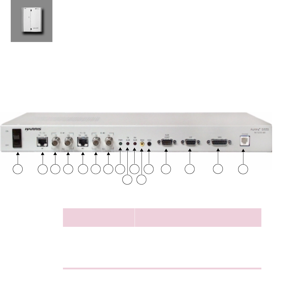
Front View
Figure 2-1 Aurora 5800 front view
Table 2-1 Aurora 5800 front panel information
23 4 5 6 7 8
9
10
11
12 13 14 15 16
1
Call-out Label Description Additional
Information
1 ON/OFF Power switch
2 T1/E1, TX, RX, #1 UTP/RJ-48C, E1/T1 interface Table 2-2
3 E1 #1 TX Coax/BNC E1 interface Use 75-ohm
cables

26 Chapter 2 Product Description
•
•
•
•
•
•
4 E1 #1 RX Coax/BNC E1 interface Use 75-ohm
cables
5 T1/E1, TX, RX, #2 UTP/RJ-48C, E1/T1 interface Table 2-2
6 E1 #2 TX Coax/BNC E1 interface Use 75-ohm
cables
7 E1 #2 RX Coax/BNC E1 interface Use 75-ohm
cables
8 PWR Power indicator LED
9 TX ALM Transmitter power alarm, red LED,
active high
10 RX ALM Receiver sync alarm, red LED, active
high
11 RSSI Receiver Signal Strength Indicator:
yellow, 0 to 4.8 volts, corresponding to
approximately receiver input level of
Σ−
90 to
−
10 dBm
12 GND Ground test jack, black
13 ALM PORT RS-232, 9-pin, DE-9 male, TX and RX
alarms by dry contact relays Table 2-3
14 CIT RS-232, 9-pin, DE-9, female, craft
interface tool port Table 2-4
15 DATA DA-15, female, asynchronous data
port Table 2-5
16 PHONE 2-wire, RJ-11, voice orderwire port Table 2-6
Call-out Label Description Additional
Information
Aurora 5800
27
•
•
•
•
•
•
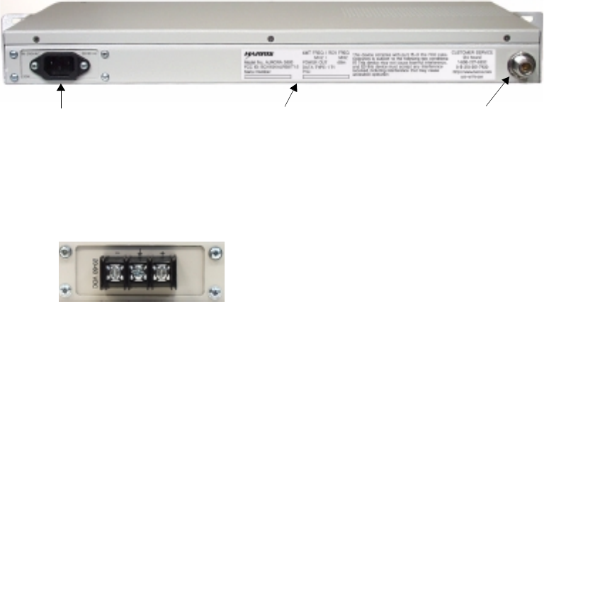
Back View
Figure 2-2
shows the Aurora radio’s back panel with an N-type antenna
connector. The standard input power connector is an AC connector as shown
in
Figure 2-2
. Optionally, if DC power is required, an input battery power
connector block (
Figure 2-3
) replaces the AC power connector.
Also, an example of a customer-service label is shown in
Figure 2-2
. This
label contains information such as technical data and serial number.
Figure 2-2 Aurora 5800 back view
DC Connector
Figure 2-3 DC connector
Customer service label N-type antenna connectorAC power connector

28 Chapter 2 Product Description
•
•
•
•
•
•
T1/E1 Line Interface
T1/E1 Interface Connector
An RJ-45 connector is provided on the front panel of the radio for this line
interface. The connection follows FCC Section 68.104(c) specified RJ-48C
standard. The pinout specification is shown in Table 2-2.
Figure 2-4 RJ-48C
Table 2-2 RJ-48C pinout specification
Unbalanced E1 Interface
A pair of BNC connectors are provided on the front panel of the radio for
this line interface, one for transmit data and the other for receive data. Use
75-ohm coaxial cables for these connections.
Pin Function
1 RRING, DS-1/E1 input to the Aurora
2 RTIP, DS-1/E1 input to the Aurora
3, 6 Not used
4 TRING, DS-1/E1 output from the Aurora
5 TTIP, DS-1/E1 output from the Aurora
7,8 GND
RRING
RTIP
NC
TRING
TTIP
NC
GND
GND
13
456782
P
P

Aurora 5800
29
•
•
•
•
•
•
Alarm Port
Dry relay contacts are provided for the TX power alarm and RX signal
alarm. Interface to third-party element manager system is through these
contacts.
The specification for the relays are listed in
Table 2-3
.
Figure 2-5 Alarm port, RS-232, male
Table 2-3 Alarm port pinout specification
Pin Signal Function
1 K1_P TX alarm relay COM
2 K1_NO TX alarm relay NO (alarm close)
3 No connection
4 K2_P RX alarm relay COM
5 K2_NO RX alarm relay NO (alarm close)
6 K1_NC TX alarm relay NC (alarm open)
7 No connection
8 No connection
9 K2_NC RX alarm relay NC (alarm open)
1
6
2
7
3
8
4
9
52
30 Chapter 2 Product Description
•
•
•
•
•
•
CIT Port
Figure 2-6 CIT port, RS-232, female
Table 2-4 CIT port pinout specification
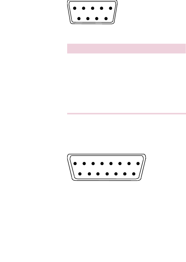
DATA Port
Figure 2-7 DA-15, female
Pin Signal Function
1 No connection
2 TXD Transmit data, RS-232
3 RXD Receive data, RS-232
4 No connection
5GND
6 to 9 No connection
1
6
2
7
3
8
4
9
52
8
14
15
76
13 12 10
11
5432
9
1
Aurora 5800
31
•
•
•
•
•
•
Table 2-5 DA-15 pinout specification
PHONE
Figure 2-8 RJ-11
Table 2-6 RJ-11 pinout specification
Pin Signal Function
1 No connection
2 RS232_TX Transmit data
3 RS232_RX Receive data
4 to 6 No connection
7GND
8 to 15 No connection
Pin Signal Function
1 No connection
2 RING Receive from handset
3 TIP Transmit from handset
4 No connection
Harris recommends phones with electronic ringers.
NOT USED
NC
RING
TIP
NC
NOT USED
234
1
P

32 Chapter 2 Product Description
•
•
•
•
•
•
Hardware Assemblies
The Aurora 5800 radio contains 7 hardware assemblies:
•Modem
•Upconverter
•TX Power Amplifier
•RX Low Noise Amplifier
•Down Converter
•Antenna Diplexer
•Power Supply
Customer-interface software is included for field-specific programming and
diagnostics. This software utility is accessed through the CIT port.
Modem
The Modem contains a Direct Sequence Spread Spectrum (DSSS) baseband
processing section, an I and Q modulator, an IF AGC amplifier with an I/Q
demodulator, and a microcontroller section.
Figure 2-9
shows the Modem
block diagram.
Transmit Direction
In the transmit direction, incoming one-channel or two-channel T1/E1
standard data is converted into NRZ data by the T1/E1 line interface circuit.
The line interface circuit also recovers the bit rate clock (1.544 MHz or
2.048 MHz) from the input tributary and then multiplexes it with the Master
Clock (MCLK) of the DSSS processor.
The voice orderwire samples the analog voice signal from the telephone
handset and compresses it to 16 kb/s. It contains a RING generator that rings
when the remote radio handset is OFFHOOK. When the handset is
ONHOOK, the channel serves as a general-purpose, asynchronous, data-
communications channel.
Aurora 5800
33
•
•
•
•
•
•
Figure 2-9 Modem block diagram
Rx Tip
Rx Ring
Tx Tip
Tx Ring
T1/E1
LINE T1/E1
LINE
INTERFACE
BASEBAND PROCESSOR
RxDATA1
RxCLK1
TxDATA
TxCLK
TxDATA1
TxCLK1
RxDATA
RxCLK
Tx
PORT DQPSK
MOD SPREAD
DE-A/D
A/D
TIMING
GENERATOR TEST
PORT
SERIAL
Rx
PORT SPREAD
MASTER
CLOCK
0°90°
I/Q MODULATOR
IF OUT
140 MHz
IF LEVEL
CONTROL
LO
0°90°
I/Q DEMODULATOR
IF IN
140 MHz
SAW BPF
140 MHz
AGC
DET
Rx SYNTHESIZER CONTROL
Tx SYNTHESIZER CONTROL
TX_CIT
TxD
RX_CIT
RxD
CAN
CONTROLLER
RS-232
INTERFACE
RS-232
TO/FROM PC
÷2
÷2
DQPSK
DEMOD
CONTROL
INTERFACE
FPGA
MUX/DEMUX
RxDATA2
RxCLK2
RxCLK1
TxDATA2
TxCLK2
280 MHz
Rx Tip
Rx Ring
Tx Tip
Tx Ring
T1/E1
LINE T1/E1
LINE
INTERFACE
Tx
Rx DA-15
INTERFACE
Tip
Ring RJ-11
INTERFACE
TO/FROM
PHONE
TO/FROM
PC OR
DATA
TERMINAL

34 Chapter 2 Product Description
•
•
•
•
•
•
An asynchronous RS-232 (CIT) port provides a 19.2 kb/s communication
link for local and remote radio configuration and monitoring.
The DATA port serves as an asynchronous data service channel that
provides a 4800 kb/s communication link.
The T1/E1 tributary, the voice orderwire channel, and the RS-232 and the
DA-15 data service channels are multiplexed to form an aggregate rate of
1.664 Mb/s, 2.176 Mb/s, 3.208
Mb/s, and 4.224 Mb/s for T1, E1, 2T1, and 2E1, respectively, which is then
inputted into the baseband processor.
The baseband processor performs scrambling, differential encoding, I and Q
symbol generation, and spreading. For DQPSK operation, the input data is
demultiplexed to become I and Q output symbols, and spread by a PN code.
The PN code is user-programmable: 15 chips for T1 rate data, and 11 chips
for E1, 2T1, and 2E1 rate data. Hence, the chip rate (fchip) is 12.48 Mcps
for T1 rate, 11.968 Mcps for E1 rate, 17.644 Mcps for 2T1 rate, and 23.232
Mcps for 2E1 rate.
The I and Q outputs from the baseband processor are input to the I/Q
modulator. The I and Q signals then modulate an IF carrier signal to generate
a 140-MHz IF DQPSK signal.
Receive Direction
The received 140-MHz IF signal is first passed through a SAW bandpass
filter, then inputted to the I/Q demodulator. The IF signal is then
demodulated into I and Q signals. The demodulator, together with a front-
end AGC amplifier, provides a total of 70 dB of AGC. The demodulated I
and Q baseband signals are then outputted to the baseband processor.
The baseband processor contains two 3-bit A/Ds, carrier and symbol
synchronization and tracking, despreading, differential decoding, and
descrambling. The quantized I and Q signals pass to a pair of
16-tap
matched filters for calculating the signal correlation with the PN sequence.
The output goes through a carrier phase rotation and acquisition process.
The baseband processor also includes a frequency loop that tracks and
removes the carrier frequency offset.

Aurora 5800
35
•
•
•
•
•
•
The PN correlator uses two samples per chip and despreads the chip rate
back to the original data rate. This process provides 10.4 dB of processing
gain for 11 chips per bit or 11.76 dB for 15 chips per bit. The correlator
output pulse is further tracked by a symbol timing loop performing bit
synchronization. The frequency and phase of the signal are corrected from
an NCO that is driven by the phase-locked loop (PLL).
Demodulation of the signal in the early stages of acquisition is done by
delay and subtraction of the phase samples. Once PLL tracking of the carrier
is established, the PLL switches to a narrower loop, which achieves a better
BER performance margin during the rest of demodulation. The
demodulated signal is further differentially decoded and descrambled, then
demultiplexed to recover the T1/E1, 2T1/2E1 tributary, the data service
channel, and the voice orderwire.
The radio uses a CAN microcontroller to provide system configuration,
including baseband processor, ADPCM codec, RF transmit and receive
frequency synthesizer initialization, control, and monitoring. The system
default configuration is initially built-in. The customer can use the
Microsoft Windows-based Aurora 5800 software to reconfigure the
baseband processor, and the transmit and receive synthesizers by using the
radio’s RS-232 interface. The new configuration can be downloaded into the
radio and stored in the controller EEPROM.
36 Chapter 2 Product Description
•
•
•
•
•
•
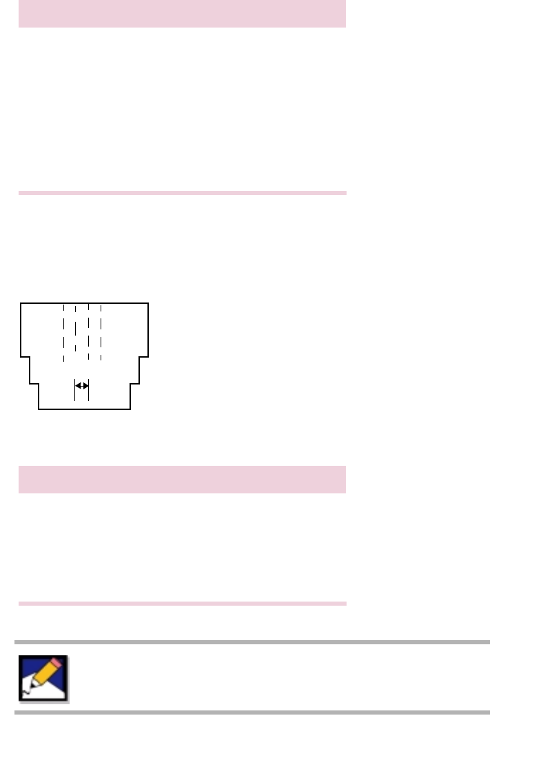
Jumper Settings
Figure 2-10 Modem, component side
SW2
SW1
JP3
JP4
JP12
JP15
JP2
JP1
JP5
JP10
JP16
JP11
JP14
JP18
JP20
JP17
JP19
JP6
JP8
JP13
JP9
JP7
2T1/2E1 RADIO MODEM
NM
K L
GH
I J
E F
C D
A B
Do not change any of the settings marked “factory use
only” in the following table. Doing so may invalidate the
warranty.

Aurora 5800
37
•
•
•
•
•
•
Table 2-7 Jumper settings
NA = Not applicable.
Jumper T1 Rate E1 Rate
120 ohms E1 Rate
75 ohms 2T1
Rate 2E1 Rate
120 ohms 2E1 Rate
75 ohms
JP1, JP2 OFF OFF ON OFF OFF ON
JP3, JP4, JP5 OFF OFF ON OFF OFF ON
JP6 to JP9 ON (normal operation); OFF (factory use only)
JP10 OFF OFF ON OFF OFF ON
JP11, JP12 OFF OFF ON OFF OFF ON
JP13 ON (normal operation); OFF (factory use only)
JP14 E (normal operation); F (CAN controller in-circuit programming)
JP15 A A B A A B
JP16 NA NA NA C C D
JP17 G (normal operation); H (CAN controller in-circuit programming)
JP18 I (normal operation); J (factory use only)
JP19 K (normal operation); L (CAN controller in-circuit programming)
JP20 M (normal operation); N (CAN controller in-circuit programming)

38 Chapter 2 Product Description
•
•
•
•
•
•
DIP Switch Settings
Table 2-8 SW1 and SW2 positions
Close = ON; Open = OFF
Table 2-9 SW1 and SW2 positions, options
Close = ON; Open = OFF
Position AMI
Encoder B8ZS
Encoder HDB3
Encoder Comment
1 OFF ON ON
2 ON (default setting) OFF (factory use only)
3 OFF ON ON
4 ON (default setting) OFF (factory use only)
5 ON (default setting) OFF (factory use only)
6
See Table 2-9.
ON
7ON
8ON
Position Option Selected Application
678
ON OFF OFF 0 to 133 feet
T1
OFF ON ON 133 to 266 feet
OFF ON OFF 266 to 399 feet
OFF OFF ON 399 to 533 feet
OFF OFF OFF 533 to 655 feet
ON ON ON 75 ohm (with JP1 and JP2 OFF)
120 ohm E1
ON ON OFF AT&T CB113 Repeater
ON OFF ON FCC Part 68, Option A Network
interface
ON OFF OFF
Aurora 5800
39
•
•
•
•
•
•
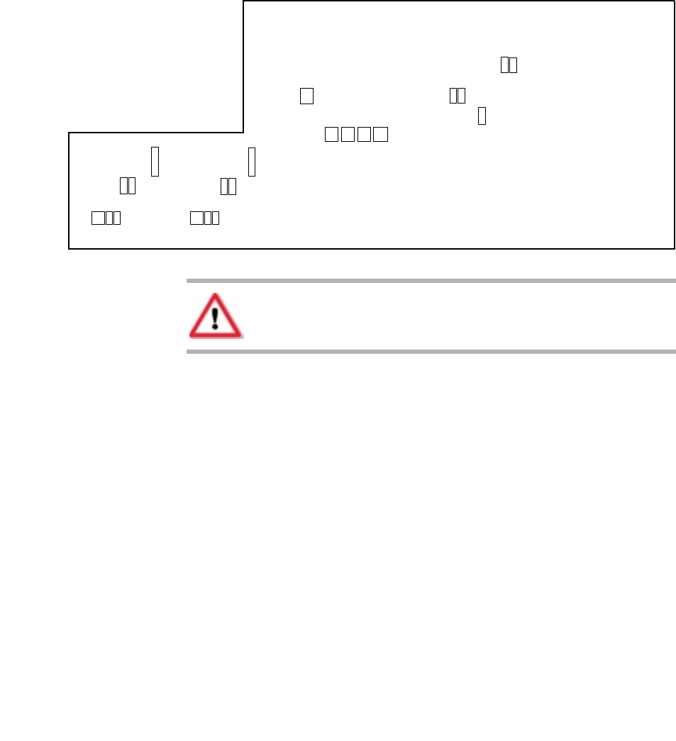
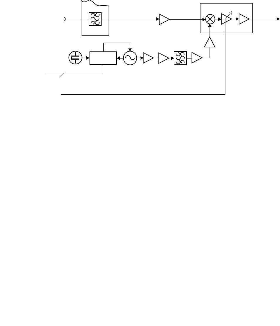
Upconverter and Power Amplifier
The Upconverter receives the 140-MHz IF signal from the modem. The
signal passes into the variable gain amplifier (VGA) section that provides
about 10 dB AGC range. The IF signal is then mixed with the LO signal that
is generated from the transmit synthesizer. The RF bandpass filter section at
the output is centered at f0 5.7875 GHz with passband BW of 125-MHz and
a minimum rejection ratio of 40 dBc at f0 + 232.5 MHz.
The filtered upper sideband RF signal then passes into the RF intermediate
power amplifier (PA) to generate a linear power up to about 0 dBm level.
The ALC function keeps the transmit PA at a constant output power level
for all the operating temperature range. The PA provides about 23 dB gain
and generates up to about +23 dBm maximum output level.
Figure 2-11 Upconverter and Power Amplifier block diagram
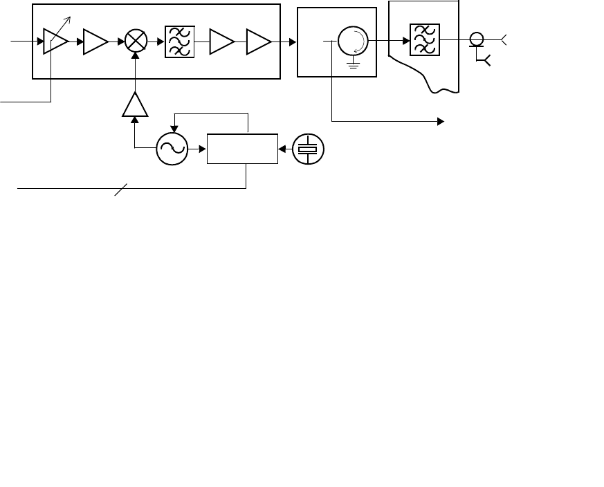
Down Converter and Low-Noise Amplifier
The incoming RF signal from the Antenna Coupling Unit (ACU) is
amplified by a Low-Noise Amplifier (LNA) and then passes into the Down
Converter (
Figure 2-12
). The signal is amplified and then mixed with the
LO signal to down-convert it to a 140-MHz IF signal.
UPCONVERTER
FROM MODEM
ALC OUT
TCXO
140 MHz IF
FROM
MODEM
½
DIPLEXER
FREQUENCY
SYNTHESIZER
TX SYNTHESIZER CONTROL
TO
ANTENNA
PWR
AMPL
TO RX RF/IF MODULE
Figure 2-12
FROM
CAN
CONTROLLER
VCO
40 Chapter 2 Product Description
•
•
•
•
•
•
Figure 2-12 Down Converter block diagram
Nominal Frequencies
The nominal frequencies of the Upconverter and Down Converter LO
synthesizers are initially set at the factory. The LO frequencies can be
reprogrammed in the field by using the Aurora 5800 utility software.
Antenna Diplexer
The antenna diplexer consists of two cavity-type filters. The transmit-
section insertion loss and the receive-section insertion loss are both less than
3 dB. The return loss is typically better than 16 dB. The diplexer provides
more than 80-dB isolation between the transmit and receive sections. This
isolation prevents the receiver LNA from being overloaded by transmitter
power leakage.
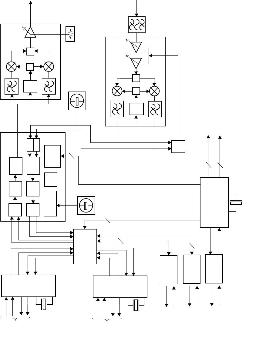
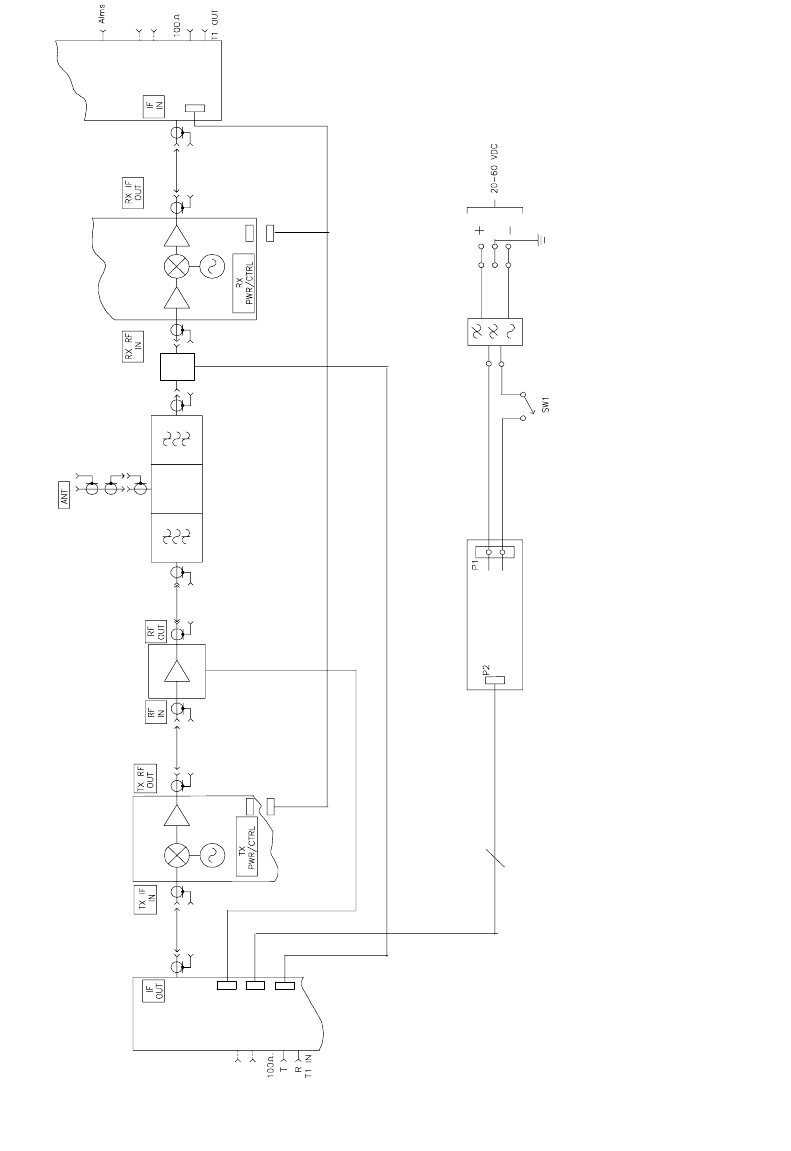
Aurora 5800 Block Diagram
Figure 2-13
is a block diagram of the Aurora 5800 radio.
FROM
CAN
CONTROLLER
TCXO
FREQUENCY
SYNTHESIZER
VCO
RX SYNTHESIZER CONTROL
LNA DOWN CONVERTER
AGC CONTROL
FROM MODEM
TO RX RF/IF MODULE
½ DIPLEXER
FROM
Figure 2-11
140 MHz IF
TO
RADIO
MODEM
Aurora 5800
41
•
•
•
•
•
•
Figure 2-13 Aurora 5800 block diagram (DC operation shown)
Power
Supply
DC/DC
6
P2
P3
LNA
P4
P1
1/2 Up/Down Converter
1/2 T1 Modem
Diplexer
Power Amplifier
1/2 Up/Down Converter

42 Chapter 2 Product Description
•
•
•
•
•
•
This page intentionally blank.

Aurora 5800
43
•
•
•
•
•
•
Chapter 3
• • • • • •
System Description
Frequency Plans
Coexistence with Other Radio Links
The Aurora can coexist with other similar radio links in the vicinity.
Operation with other links can be achieved through the use of different
spreading codes, frequencies, “building blockage”, and antenna pattern and
polarization separation. In congested urban areas, Harris recommends the
use of a larger, more directional antenna; the narrower beam width allows
less interference into the receiving Aurora and lowers interference levels
into other radios in the vicinity.
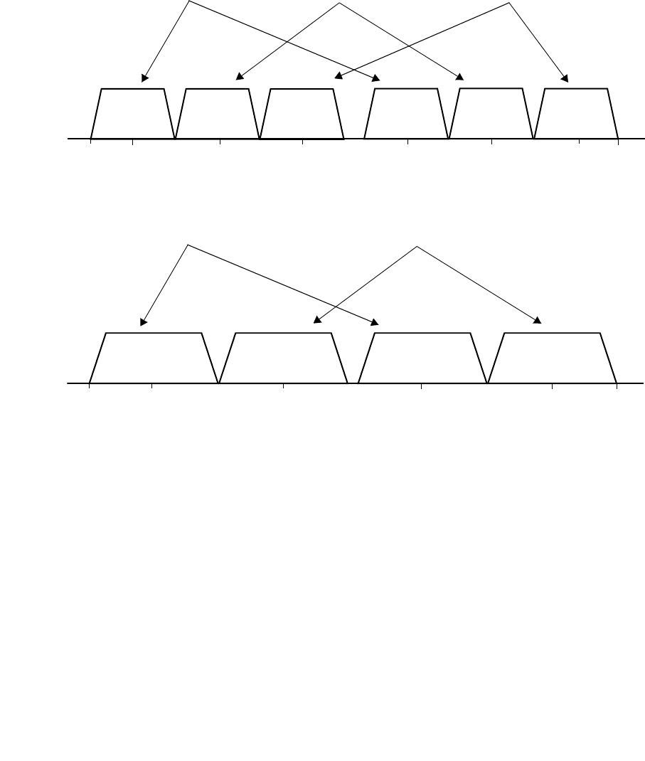
Aurora Frequency Plan
The Aurora has one standard frequency plan available.
Figure 3-1
and
Figure 3-2
illustrate this plan. The “A” frequency pair uses the first and
third frequencies shown. One site transmits on A1 and receives on A2. The
site at the opposite end of the link transmits on A2 and receives on A1. The
“B” frequency pair uses the second and fourth frequencies shown in the
illustration. One of the two pairs may work better than the other in a
particular area based on the nature of the interference.
44 Chapter 3 System Description
•
•
•
•
•
•
Figure 3-1 Aurora 5800 T1/E1 frequency plan
Figure 3-2 Aurora 5800 2T1/2E1 frequency plan
Spread Sequence Pseudo-random Number (PN) Selection
The Aurora radio can be configured with different spread sequence codes.
The use of different codes on nearby Aurora 5800 co-channel links ensures
interlink privacy. However, the assignment of different codes to adjacent or
nearby links does not lower interference levels. Co-channel interference
may degrade receiver thresholds and thus reducing fade margins, which
increases multipath outages in Aurora links, but usually not beyond the
link’s outage objective.
The Aurora 5800 has four preset PN spread sequence codes. Every unit
shipped to a customer contains a default code.
A1 B1 A2 B2
5725
“A” Frequency Pair “B” Frequency Pair
C1 C2
MHz
5735 5755 5775 5800 5820 5840 5850
“C” Frequency Pair
A1 B1 A2 B2
5725
“A” Frequency Pair “B” Frequency Pair
MHz
5741 5772 5803 5834 5850
Aurora 5800
45
•
•
•
•
•
•
Aurora 5800 Radio Configurations
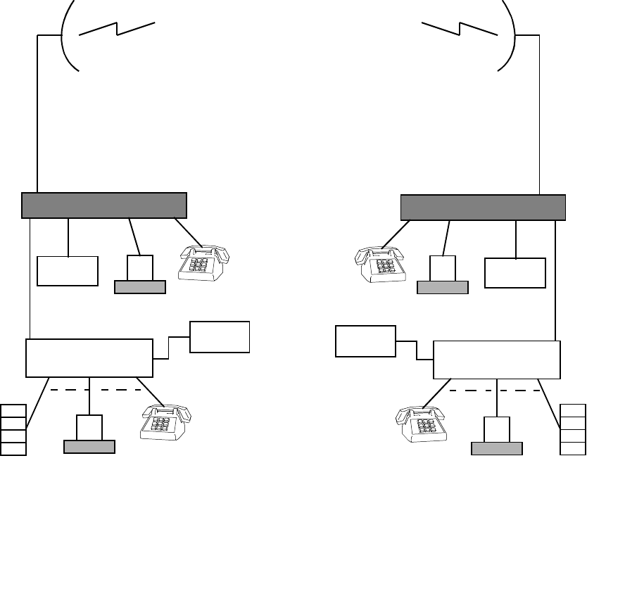
Point-to-Point Configuration
In a point-to-point configuration, two radios communicate only with each
other. Either or both of the radios may be mobile, as long as they remain
within each other’s range.
Figure 3-3
shows a typical point-to-point radio setup.
Figure 3-3 Point-to-point configuration
Aurora 5800
Digital Radio Aurora 5800
Digital Radio
RF Path
Directional
antenna Directional
antenna
User Equipment
T1/E1 Multiplexer
PBX Computer
User Equipment
T1/E1 Multiplexer
PBX
Computer
Computer
Video
conference
Directional
T1/E1
access
Video
conference
Computer
T1/E1
access
Antenna coax
cable
Antenna coax
cable

46 Chapter 3 System Description
•
•
•
•
•
•
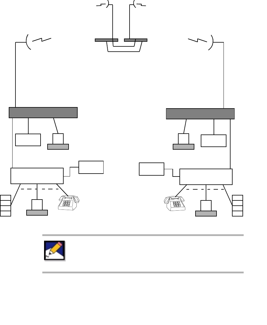
Repeater Configuration
A repeater extends the maximum communication range beyond that of a
single hop. In this configuration, two additional radios are installed between
the terminal radios in the hop. Each of these intermediate radios faces one
of the terminal radios in the hop. A transmission from one end of the hop is
received by the repeater radio facing it, is passed on to the other radio in the
repeater, and then relayed to the far-end radio.
Figure 3-4
illustrates this
configuration.
Besides Aurora 5800 “active repeaters”, other 5.8 GHz repeater options are
available, including “passive reflectors” and “beam benders” (back-to-back
antennas) if one RF path is very short, and solar-powered “RF” repeaters.
Aurora 5800
47
•
•
•
•
•
•
Figure 3-4 Repeater configuration
Aurora 5800
Digital Radio Aurora 5800
Digital Radio
RF Path
antenna Directional
antenna
User Equipment
T1/E1 Multiplexer
PBX Computer
User Equipment
T1/E1 Multiplexer
PBX
Computer
Computer
Video
conference
Directional
T1/E1
access
Video
conference
Computer
T1/E1
access
Aurora 5800
Repeater
RF Path
Antenna coax
cable Antenna coax
cable
For repeater configurations, make sure there is enough
frequency separation on the two transmitting channels. Use
different antenna directions, polarization, or channel
frequencies to achieve this separation.

48 Chapter 3 System Description
•
•
•
•
•
•
Multihop and Hubbing Arrangements
Network Planning
Three transmit/receive frequency pairs are available to single T1/E1 links,
and two pairs are assigned to 2T1/2E2 links for hubbing and multihopping
Aurora 5800 radio links in the 5735 to 5850 MHz ISM band (see
Figure 3-1
).
T1/E1, 20-MHz bandwidth, go/return RF channels:
•Pair A: 5735/5800 MHz
•Pair B: 5755/5820 MHz
•Pair C: 5775/5840 MHz
2T1/2E1, 31-MHz bandwidth, go/return RF channels:
•Pair A: 5741/5803 MHz
•Pair B: 5772/5834 MHz
Any of these duplex RF channels may be assigned a new Aurora 5800 link,
taking into consideration possible interference to and from other links in the
area that has been assigned the same channels.
Each spread-spectrum radio in the area has a discrete PN spread sequence
code assigned by user selection, as explained on
page 44
. While the use of
different PN codes does mitigate the effect of external interference on the
victim radio’s thresholds and fade margins by a minimal amount, perhaps by
only a dB or two, it does ensure that only wanted data is demultiplexed on
a link.
Interference into a digital receiver is acceptable as long as it does not
degrade its threshold (fade margin) for increased outage or degraded
errored-second performance beyond the user’s performance objectives.
Many shorter Aurora 5800 links may be so deployed with very low (< 20
dB) fade margins, permitting very high levels of co-channel interference
that would otherwise be unacceptable on longer fading hops.

Aurora 5800
49
•
•
•
•
•
•
The planning of a complex network of Aurora 5800 links may include the
following:
•The selection and placement of antennas on towers, rooftops, and
building walls
•RF channel and polarization assignments
•Aurora 5800 power output adjustments and PN spread sequence code
selections
•The calculation of acceptable levels of interference, accommodating the
link’s fade characteristics and performance objectives
With careful planning, even the most complex Aurora 5800 networks and
systems may be commissioned in most areas.
Parallel-Path Arrangement for Higher Capacity
or Protection
Two Aurora 5800 radios that are assigned the same frequency pair may be
paralleled on a single path either with dual-polarized antennas or separate
cross-polarized antennas positioned at similar heights. With these separate
antennas at the same elevation, paralleled paths fade together, ensuring that
the > 9 dB carrier-to-interference (C/I) ratio objective for error-free data
transmission is maintained at all times.
A single-polarized antenna may also be assigned to provide either a
protection channel (through a T1 switch) or to double the link capacity. The
requirement is, however, that the radios be assigned different RF channel
pairs and that 3-dB hybrid couplers combine these radios to a common
antenna feed system. This additional 6-dB path loss is acceptable in meeting
the user’s performance objectives on most shorter paths.
Multihop Networking Arrangement through Repeaters
Longer Aurora 5800 paths of hops connected in tandem fade independently,
that is, a victim path could fade to its threshold (outage) point while the co-
channel interference from another path is high.

50 Chapter 3 System Description
•
•
•
•
•
•
The two interference mechanisms are:
•Receive backside reception from and transmit backside radiation to an
adjacent link
•Overshoot from a path two hops away
Backside interference is eliminated by the assignment of different RF
channels on adjacent hops out of a repeater by a “four-frequency” plan (two
duplex channels).
Interlink overshoot interference is mitigated by cross-polarizing every other
hop, H-H-V-V-H and so forth, on tandem systems; and/or by ensuring that
the links are not deployed in a straight line, that is, path azimuths are
staggered by at least 3 to 5 degrees for adequate antenna discrimination to
overshoot interference.
Hubbing (Star) Networking Arrangement Out of a Node
Aurora 5800 spur links out of a node or repeater site provide point-to-point
T1/E1 connectivity to multiple sites in an area. With the limited number of
two or three RF channel pairs available to a user, co-channel interference out
of a nodal site must be taken into consideration so that link performance
beyond the user’s objectives will not be degraded.
Interference into other links out of a hub site is mitigated by the following
examples:
•Use of different RF duplex channels
•Cross-polarization between links
•(Usually larger or shrouded) antennas with higher discriminations
•Reduced power outputs on short paths
•Blockage with antennas positioned on the opposite sides of buildings or
elevator penthouses
•PN code selection to prevent intelligible crosstalk
•Changing some links to Aurora 2400 (in the 2.4 GHz band)

Aurora 5800
51
•
•
•
•
•
•
Wanted and Unwanted Signal Path Antennas at a Hub Site
At the Same Elevation (correlated path fading)
With antennas assigned to the wanted and interfering (co-channel)
interference paths at the same elevation, C and I tend to fade together. This
tendency lowers the C/I objective to about 9 dB, similar to the parallel-path
example on
page 49
. It is necessary only to cross-polarize the interference
and wanted paths for > 20-dB isolation to meet this objective easily.
At Different Elevations (independent path fading)
At hub sites with independently fading wanted and interfering signals, C/I =
the interfering transmission signal’s antenna discrimination to the victim
path’s azimuth.
Interference does not affect the performance of an Aurora 5800 link if the
following C/I ratio is not exceeded.
C/I = Fade Margin + T/I
= Required Tx Antenna Discrimination, dB
where
•Fade Margin is the victim radio link’s fade margin necessary to meet its
outage objectives, typically 15 to 35 dB.
•T/I is the victim receiver’s threshold-to-interference ratio. For the Aurora
5800 (
Figure E-10
):
15 dB, co-channel
−
15 dB, adjacent channel
Therefore, if a longer Aurora 5800 link is assigned antennas to provide a 35-
dB fade margin (
−
55 dBm median RSL) to meet its outage objective (see
Chapter 5
), the C/I ratio at the victim receiver should not exceed about 35
+ 15 = 50 dB (
−
105 dBm interference level).
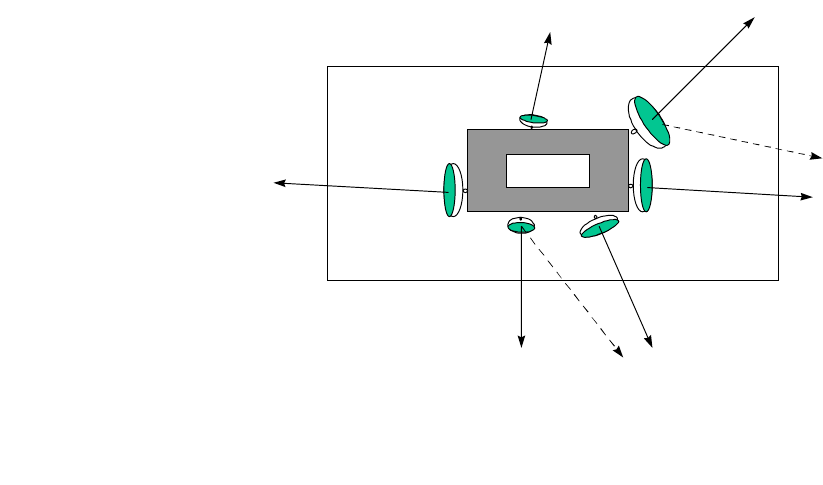
52 Chapter 3 System Description
•
•
•
•
•
•
In this case, a standard 4-foot parabolic antenna with > 100/135 degree
discrimination angle for co- and cross-polarized paths respectively (or a 6-
foot antenna with 30/90 degree discrimination angles) to the interfering
radio at the hub site would be suitable.
If a shorter Aurora 5800 link’s outage objective is met with only 20-dB fade
margin, and the computed free-space RSL is the same (-55 dBm), a lower
20 + 15 = 35 dB C/I is acceptable (
−
75 dBm interference level). Then,
Aurora 5800 radio’s standard 2-foot square antenna, cross-polarized to the
victim link, is suitable.
Hubbing Examples
Hubbing arrangements are categorized as blocking and nonblocking.
Blocking Arrangement
To introduce blockage, Aurora 5800 radio’s antennas are positioned on the
opposite sides of the building roofs, water tanks, microwave shelters, and so
forth, thus greatly reducing interfering signal coupling between links. See
Figure 3-5
.
Figure 3-5 Roof mounting with building blockage
10oT
Short path
(1T1/E1)
45oT
Long path
2T1/E1)
95oT
Long path
(2T1/E1)
165oT
Short path
(1T1/E1)
275oT
Long path
(2T1/E1)
Elevator
Penthouse
Building Roof
195oT
Short path
(1T1/E1)
A
B
C
D
EF

Aurora 5800
53
•
•
•
•
•
•
Channel Assignments for the Long 2T1/E1 Paths
Antenna A is placed on the opposite side of the elevator penthouse hut from
antennas B and C on the building roof. The blockage provided by the hut
reduces the interference level > 20 dB between path A to the west, and paths
B and C to the east, permitting the co-channel assignment of A to B or C
even on co-polarized paths with small antennas.
Exposed interference paths are shown–path B to/from path C, for example.
With only a single antenna discrimination and no interference blockage,
paths B and C are assigned adjacent channels with cross-polarization.
Paths E and F are short with low fade activity; so higher interference levels
with smaller antennas are permitted.
As previously discussed, the required antenna discrimination is computed
from
C/I = Required Fade Margin + T/I.
In the long A, B, and C paths, the required fade margin necessary to meet
the performance objectives might be 35 dB. For a co-channel operation, the
T/I is 15 dB, requiring 50 dB of antenna discrimination. 4 ft (1.2 m) antennas
cross-polarized between paths B and C provide this necessary
discrimination with a path azimuth differences > 20
o
. All three paths are
thus assigned the same RF channel with B cross-polarized to A and C.
Channel Assignments for the Short 1T1/E1 Paths
Assignments to these shorter paths are to the channels adjacent to the long
paths to reduce the interference level by > 30 dB. The short paths may be
assigned 2 ft (0.6 m) dishes, with paths E and F cross-polarized. These
smaller cross-polarized antennas provide about 43 dB discrimination
between paths E and F, which meets the 25 + 15 = 40 dB C/I objective (25
dB required fade margin and 15 dB co-channel T/I).
The Aurora 5800 transmitter power outputs on the short paths E and F may
be reduced to lower the interference levels. This process reduces fade
margins while still meeting the performance objectives on these short paths.
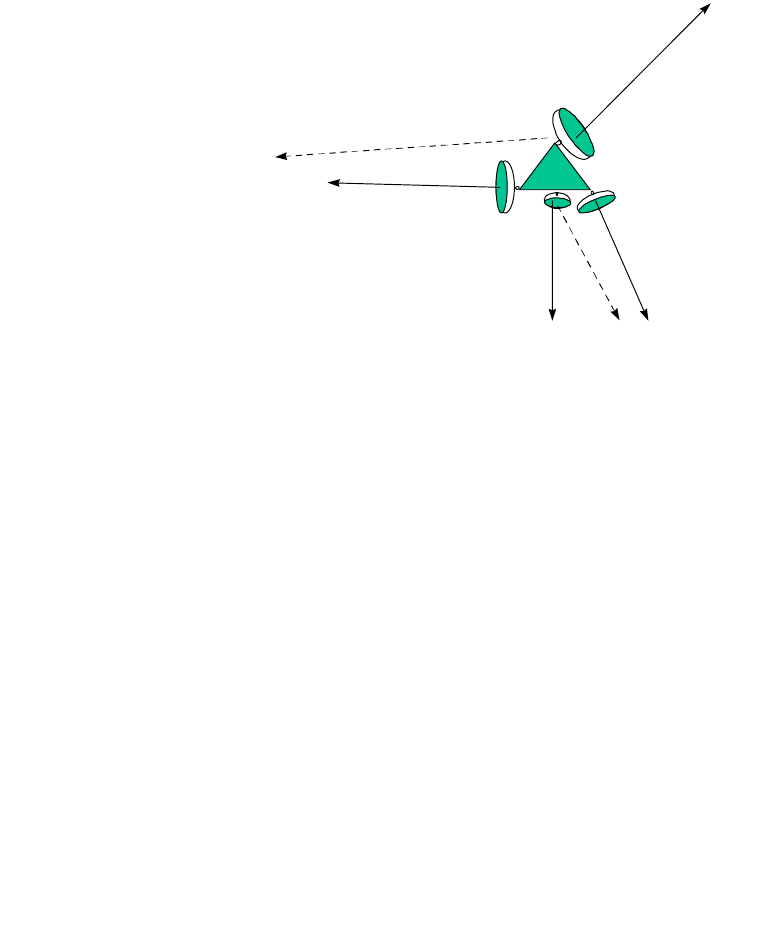
54 Chapter 3 System Description
•
•
•
•
•
•
Figure 3-6
shows a hubbing example at sites with no interlink blockage, as
often occurs with tower-mounted antennas. In this arrangement, channel
assignments made to a large number of links at a common hubbing site may
take into account additional cases of acceptable levels of threshold (fade
margin) degradation.
Figure 3-6 Tower mounting with no blockage
Channel assignments are first made to the longer, fading paths. With no
blockage, larger antennas provide higher discriminations between the
longer paths. A and D are co-channel cross-polarized; C and D are assigned
an adjacent channel cross-polarized, with perhaps > 5 dB of allowable
threshold degradation taken on these short nonfading hops.
Of course, in very difficult cases (many long fading hops out of a hubbing
site, for example), HP antennas with shrouds providing > 20 dB additional
discrimination may be assigned.
Conclusion
These hubbing examples are but a few of the many hubbing acceptable
arrangements for Aurora 5800 links. Nearly any number of Aurora 5800
links can be hubbed at a single site, with RF channel assignments, path
polarizations, antenna sizes and types, Aurora 5800 power output
adjustments, acceptable fade margin degradation to short nonfading hops,
and PN code selection all carefully considered to meet the network’s
performance objectives.
165oT
Short path
(1T1/E1)
275oT
Long path
(2T1/E1) 195oT
Short path
(1T1/E1)
45oT
Long path
1T1/E1)
A
B
CD

Aurora 5800
55
•
•
•
•
•
•
Harris MCD Service
Harris Microwave Communications Division can provide rapid assistance
in the optimum selection of antenna feed systems that meet regulatory and
performance objectives for any specific Aurora 5800 single link, paralleled
link, multihop, or hubbing application necessary to meet the user’s
networking arrangement and performance objectives.

56 Chapter 3 System Description
•
•
•
•
•
•
This page intentionally blank.

Aurora 5800
57
•
•
•
•
•
•
Chapter 4
• • • • • •
Technical Specifications
Features
•5.725 to 5.85 GHz ISM bands
•Point-to-point, line of sight up to 15 miles (24 km) (standard 28-dBi, flat-
panel antenna)
•Full frequency duplex operation
•Standard T1 (DSX-1) or E1 (CEPT-1), and 2
×
T1 or 2
×
E1 interfaces
•Typical RF power, +19 dBm
•Direct sequence spread spectrum coding and DQPSK modulation
•
−
88 dBm (T1/E1) and
−
86 dBm (2
×
T1/2
×
E1) typical receiver threshold
at BER
=
10
-6
•Synthesized transmitter and receiver frequencies
•Three frequency-channel plans for T1/E1 and two frequency-channel
plans for 2T1/2E1
•Digital voice orderwire and data wayside traffic
•Craft Interface Tool (CIT) interface for local and remote radio
monitoring and control
•Supports repeater configuration
•SNMP network management with external proxy agent

58 Chapter 4 Technical Specifications
•
•
•
•
•
•
Performance (One Hop)
System Gain (at BER
=
10
-6
)
Frequency Plan (Standard)
Acquisition Time
< 50 ms
Transmission Delay
Carrier
Designator Value
T1/E1 107 dB
2
×
T1/2
×
E1 105 dB, typical
Carrier
Designator Frequency
Pair Band
(GHz)
T1/E1
A 5.735 5.800
B 5.755 5.820
C 5.775 5.840
2T1/2E1 A 5.741 5.803
B 5.772 5.834
Path Time
(
µ
s, max.)
Radio only 50
10 mi/16 km 100
20 mi/32 km 150

Aurora 5800
59
•
•
•
•
•
•
Dispersive Fade Margin
Better than 60 dB at BER = 1
×
10
-3
MTBF
430,000 hours
Transmitter
Specifications
PN Code and Chip Rate
Barker or Modified Barker Codes:
Characteristic Value
Output power +19 dBm, typical at antenna port (+10 dBm min.)
Power density < +8 dBm/3 kHz
Spurious/Harmonics <
−
60 dBc
Frequency range 5.725 to 5.85 GHz
Frequency stability Within
±
20 kHz
Frequency selection Synthesizer default value stored in MCU, and software-
selectable
Increments 500 kHz
IF frequency 140 MHz
Modulation Direct Sequence Spread Spectrum, DQPSK
Data Rate Chip Rate
T1 (Aggr. 1.664 Mb/s) 15 chips/bit, 12.48 Mcp/s
E1 (Aggr. 2.176 Mb/s) 11 chips/bit, 11.968 Mcp/s
2T1 (Aggr. 3.208 Mb/s) 11 chips/bit, 17.644 Mcp/s

60 Chapter 4 Technical Specifications
•
•
•
•
•
•
Receiver
Specifications
Receiver Level
Receiver Level at 10-6 BER
Characteristic Value
Noise figure 8 dB max. at antenna port
Image rejection 80 dB minimum
AGC range 70 dB
Frequency selection Synthesizer default value stored in MCU, and software-
selectable
Increments 500 kHz
IF frequency 140 MHz
Processing gain
≥
10 dB
Demodulation Noncoherent (matched filtering correlation)
Carrier acquisition range Better than
±
100 kHz
Carrier tracking range Better than
±
150 kHz
Clock acquisition range Better than
±
100 PPM
−
40 dBm nominal
−
20 dBm max., no performance degradation
−
10 dBm max., no damage
Threshold T1/E1 2T1/2E1
Maximum
−
89 dBm
−
87 dBm
Typical
−
90 dBm
−
88 dBm

Aurora 5800
61
•
•
•
•
•
•
Antenna/Diplexer
Specifications
Frequency Spacing
C-Band
Characteristic Value
Antenna (optional) 28-dBi gain, flat-panel antenna
Mechanics External antenna, internal ACU
Antenna port N-type female connector
Impedance 50 ohms
Return loss
≥
18 dB
ACU RF filter type Cavity diplexer with internal temperature compensation
Carrier Designator Value
T1/E1 65 MHz T-R
2T1/2E1 62 MHz T-R

62 Chapter 4 Technical Specifications
•
•
•
•
•
•
Digital Data Interface
Data Capacity
•1
×
T1 or
•1
×
E1 or
•2
×
T1 or
•2
×
E1
T1 Specifications
Pulse Shape
Characteristic Specifications
Digital interface DSX-1, meets ITU-T G.703, G.824, AT&T Pub 62411,
Bellcore GR-499-CORE
Connector RJ-48C, balanced, 100 ohms
Line code B8ZS or AMI (DIP switch selectable)
Continuity Input T1 signal, 1.544 Mb/s
±
130 PPM
Pattern should be pseudorandom
≥
2
15
−
1
Requirement: error-free performance
Minimum input level
−
6 dB below nominal (0 dB = 2.4 Vp)
Meets ITU-T G.703 mask as shown in Figure 4-1.
Pattern should be pseudorandom
≥
2
15
−
1
Requirement: error-free performance
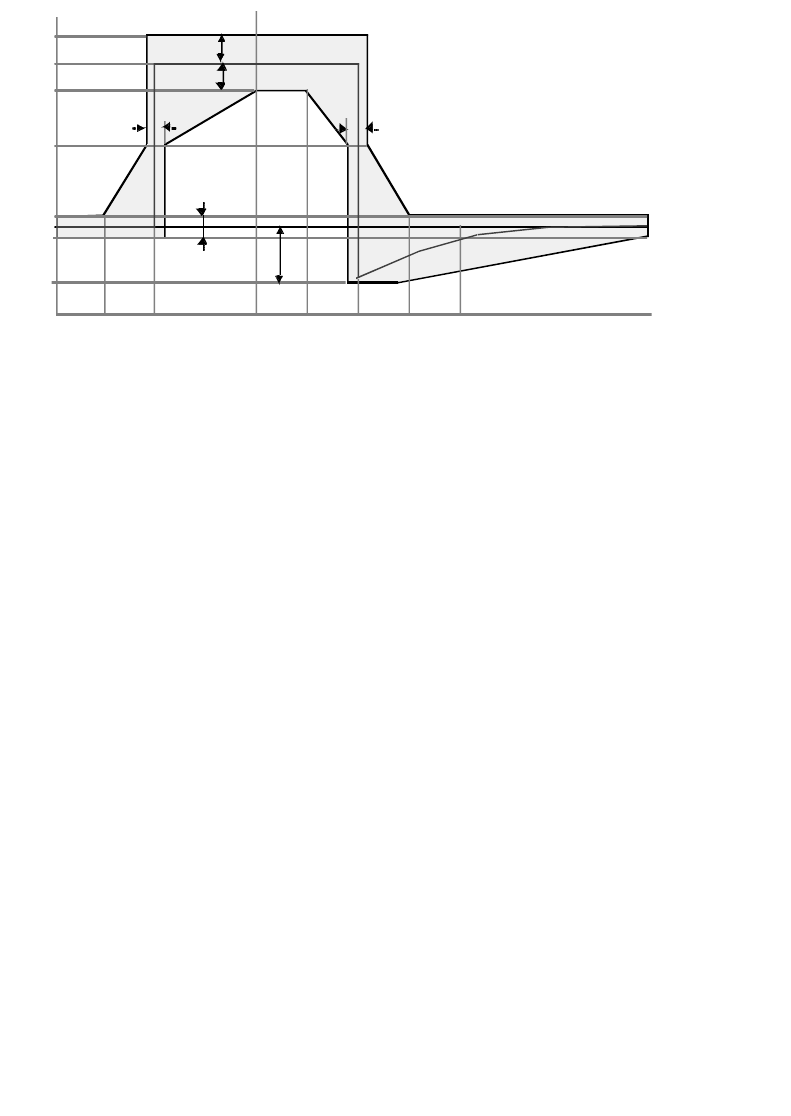
Aurora 5800
63
•
•
•
•
•
•
Figure 4-1 Pulse mask for T1
Jitter
Output Jitter
According to ITU-T G.824, the peak-to-peak limit is as follows:
B1 5.0 UI BPF cutoff: lower 10 Hz and high 40 kHz
B2 0.1 UI BPF cutoff: lower 8 Hz and high 40 kHz
0
3
.0
1
.5
0. 70. 7
50 ns 50 ns
0.3
1. 2
-3T/1 -T/4 0 T/4 3T/8 T/2T/8
V
TIME CCITT-3249 2
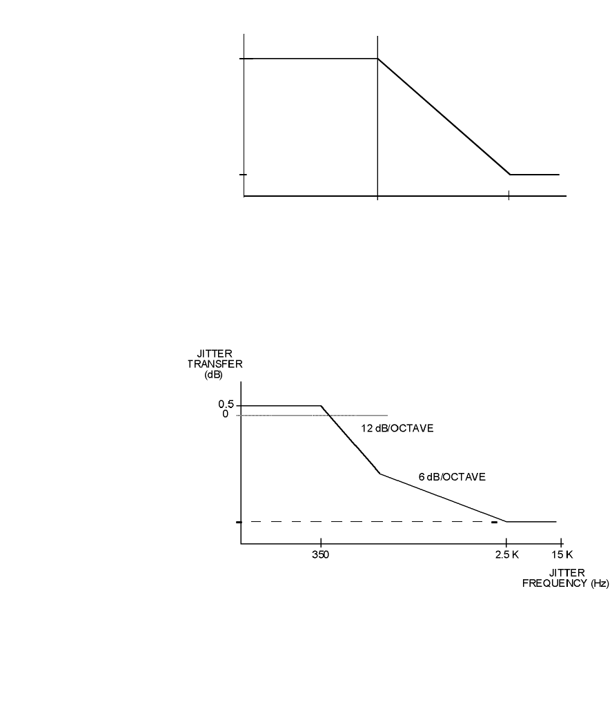
64 Chapter 4 Technical Specifications
•
•
•
•
•
•
Input Jitter Tolerance
Figure 4-2 Input jitter tolerance
Jitter Transfer Function Tolerance
Figure 4-3 Jitter transfer function tolerance
JITTER
A
MPLITUDE
(UIpp)
5
0.1
500 8 K JITTER
FREQUENCY (Hz)
− 54
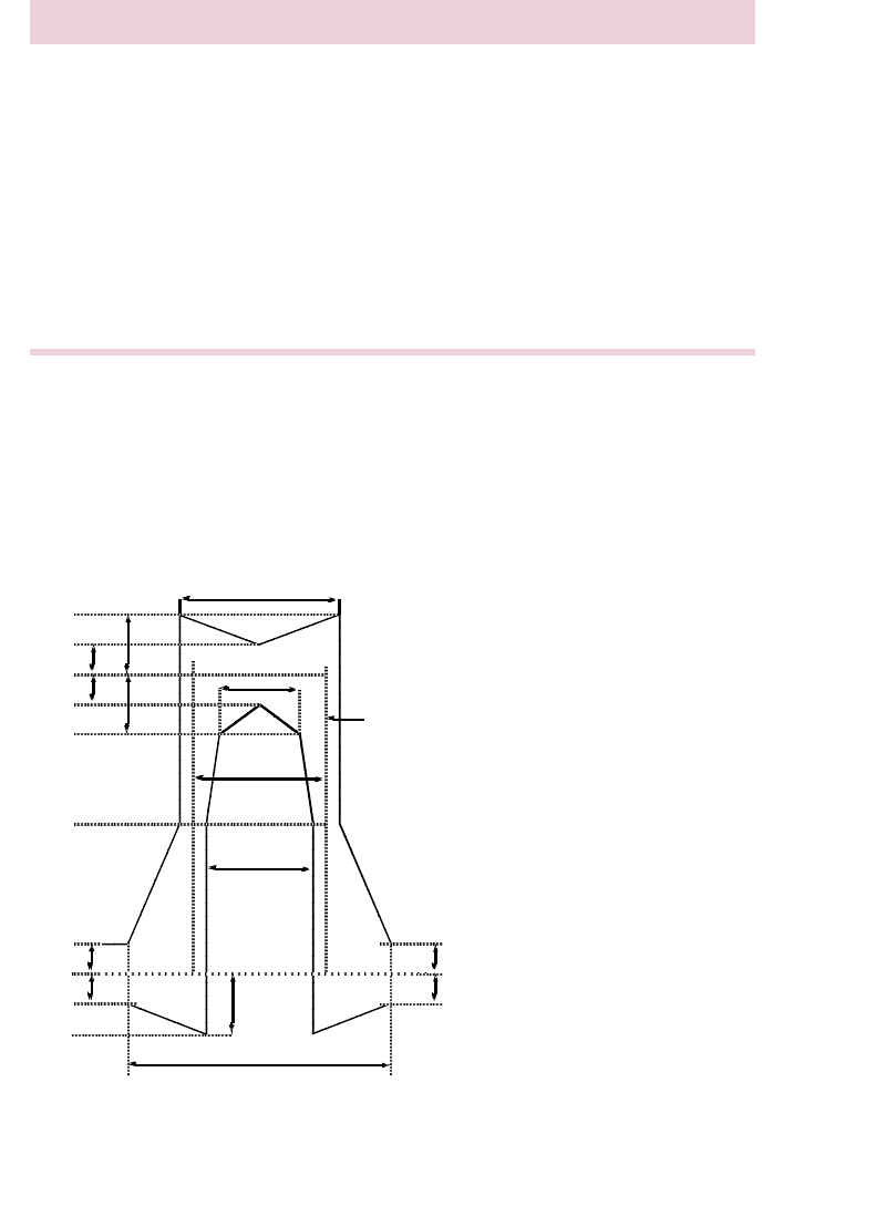
Aurora 5800
65
•
•
•
•
•
•
E1 Specifications
Pulse Shape
Meets ITU-T G.703 mask as shown in
Figure 4-4
.
Figure 4-4 Pulse shape
Characteristic Specifications
Digital interface CEPT-1, meets ITU-T G.703, G.823
Connector BNC, unbalanced, 75 ohms, or
RJ-48C, balanced, 120 ohms
Line code HDB3 or AMI (DIP switch selectable)
Continuity Input E1 signal 2.048 Mb/s
±
50 PPM
Pattern should be pseudorandom > 2
15
-1
Requirement: error-free performance
Minimum input level
−
12 dB below nominal (0dB = 2.4 Vp)
269 ns
(244+25)
194ns
(244-50)
244ns
219ns
(244 -25)
488 ns
(244 + 244)
V =100%
50%
0%
Nominal pulse
20%
10%
10% 10%
10%
10%
10%
20%
20%
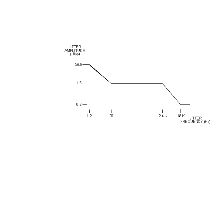
66 Chapter 4 Technical Specifications
•
•
•
•
•
•
Jitter
Output Jitter
According to ITU-T G.823, the peak-to-peak limit is as follows:
Input Jitter Tolerance
Figure 4-5 Input jitter tolerance
B1 1.5 UI BPF cutoff: lower 20 Hz and high 20 kHz
B2 0.05 UI BPF cutoff: lower 18 kHz and high 100 kHz
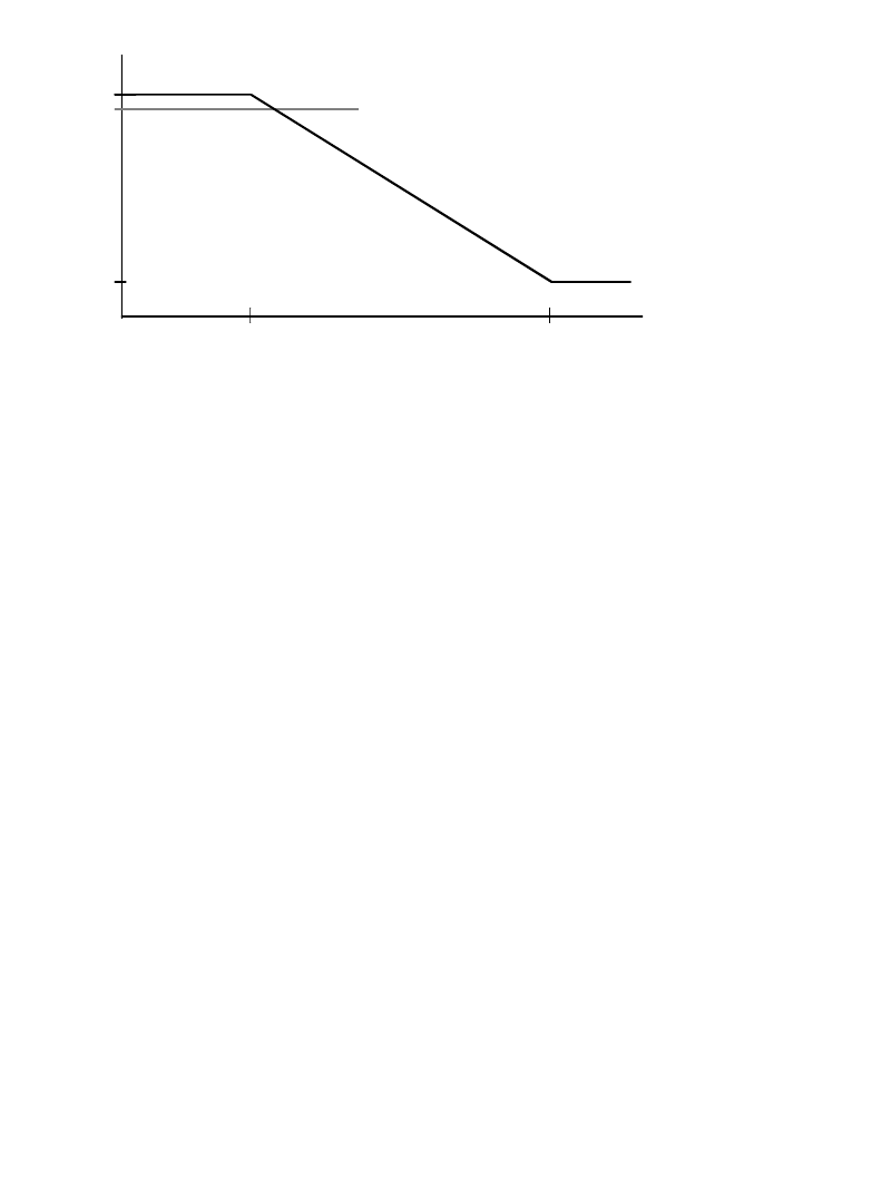
Aurora 5800
67
•
•
•
•
•
•
Jitter Transfer Function
Figure 4-6 Jitter transfer function
JITTER
T
RANSFER
(dB)
0.5
0
-19.5
1.4 K 11.4 K JITTER
FREQUENCY (Hz)

68 Chapter 4 Technical Specifications
•
•
•
•
•
•
Ports, Indicators, Test Points, and Alarms
Ports
Programmability
Default system factory-configured
Software-programmable with a PC through RS-232 CIT port
Front-Panel LED Indicators
Front-Panel Test Jacks
Port Specifications
ALARM TX and RX alarms by dry contact relays, DE-9, male
DATA DA-15, asynchronous, female
PHONE Voice orderwire, 2-wire, RJ-11
PHONE Voice orderwire, 2-wire, RJ-11
Label Color Indication
PWR Green Power is on
TX ALM Red, active high Transmitter power alarm
RX ALM Red, active high Receiver sync alarm
Label Test
RSSI Receiver Signal Strength Indicator: yellow, 0 to 4.8
volts, corresponding to approximately receive input
level of
−
90 to
−
20 dBm
GND Ground, black

Aurora 5800
69
•
•
•
•
•
•
Built-in Diagnostics (through RS-232)
•SIGNAL LOSS
•AIS
•RX synthesizer lock alarm
•TX synthesizer lock alarm
Power Specifications
Environmental Specifications
Characteristic Value
Input Voltage AC supply: Universal AC 100 to 250 V
DC supply:
±
21 to 60 V
Output Voltage +5 V, 3 A, maximum
+12 V, 2 A, maximum
−
5 V, 0.3 A, maximum
Power Consumption 30 watts, maximum
Fuse Built in with the power supply
Characteristic Value
Operational Temperature 0 to +50
°
C
32
to 122
°
F
Storage Temperature
−
40 to +70
°
C
−
40 to 158
°
F
Humidity 95% noncondensing
Altitude (above sea level) 4,572 meters 15,000 feet

70 Chapter 4 Technical Specifications
•
•
•
•
•
•
Mechanical Specifications
The Aurora 5800 radio requires one rack-mounting space (RMS) for a rack,
plus one open RMS above and one open RMS below, or table-top placement
in an indoor environment. For placement outdoors this radio can be installed
in an outdoor cabinet.
Characteristic Value
Height 1.75 inches 45 mm
Width 17 inches 432 mm
Depth (including the connectors) 11.8 inches 300 mm
Weight 7.7 lb 3.5 kg

Aurora 5800
71
•
•
•
•
•
•
Chapter 5
• • • • • •
Installation Planning
General
Spread-spectrum, point-to-point radio relay links like Aurora’s are allowed
by various regulatory agencies to operate unlicensed on a “no-interference,
nonprotection basis”. Because of the unlicensed nature, the Aurora radios
require neither licensing nor prior frequency coordination in most regions,
including the U.S.A.
Caveat
The Aurora installation software with its adjustable power feature is for
professional installer use only, as mandated by the Federal Communications
Commission (FCC, Part 15).
Harris Corporation does not assume any liability or damage arising out
of the application or misuse of this Aurora radio product and its
software.
Interference
While it is expected that many Aurora 5800 links will be deployed in urban
areas that are (or will be) frequency-congested, the robust nature of the
digital modulation and spread spectrum technology should mitigate any
noticeable customer traffic degradation caused by interference.

72 Chapter 5 Installation Planning
•
•
•
•
•
•
However, good engineering judgment should be exercised by the operator
and professional installer before selecting paths or locations near equipment
or facilities that could generate interfering signals. Such equipment might
include high-power ISM devices. Additionally, precaution should be taken
when links are deployed in a region where a large number of other 5.8-GHz,
point-to-point or point-to-multipoint links are installed.
In some interference cases, threshold degradation causing an increase in
short-term multipath outage or a slightly degraded Residual Bit Error Ratio
(RBER) may occur, either or both of which can probably be tolerated.
As a general rule, the deployment of a larger antenna with a smaller beam
width and higher front-to-back ratio, an antenna relocation for better
interference shielding, or a polarization change are often very effective in
mitigating most interference cases. These subjects are discussed in a later
section. Such field changes, to mitigate interference and to otherwise
improve Aurora 5800 link performance, require no prior regulatory
approval in unlicensed links.
Performance and Economic Considerations
Aurora 5800 microwave transport offers significant technical and economic
advantages over conventional copper- or fiber-based leased or owned
transport alternatives when availability, cost-effectiveness, implementation
time, security, and difficult terrain or access are significant network design
considerations.
Ref. [
1
] describes how the economic and technical challenges of creating a
new telecommunications infrastructure are met more effectively with point-
to-point radio links than with traditional wireline-based solutions.
When Aurora 5800 digital transport facilities are compared to conventional
leased-line services, the following four factors are taken into consideration:
•Transmission quality and reliability
•Circuit availability
•Short-haul costs
•Construction time

Aurora 5800
73
•
•
•
•
•
•
The infrastructure of most telephone networks has inherent regulatory or
technical characteristics that limit its ability to meet microwave’s superior
transmission quality, reliability, and other performance and availability
characteristics.
It is not unusual for the telephone company’s “local loop” subscriber facility
to have an RBER of 100 times, or more, worse than microwave links along
with a long-term outage (unavailability) measured in hours per year. Simple
and highly reliable Aurora 5800 microwave links can provide customers
with superior service.
Microwave’s short-term reliability standards, in excess of 99.995% to
99.999% (a few minutes outage per year), are often significantly better than
those associated with typical leased copper services.
74 Chapter 5 Installation Planning
•
•
•
•
•
•
Antenna Installation
Instructions for antenna installation usually are part of the antenna kit.
Follow these instructions for good and effective antenna installation.
Radio performance is affected by all aspects of antenna installation,
including:
•Antenna type
•Line-of-sight path fade characteristics
•Antenna orientation
•Antenna placement
•Distance between antennas
•Distance between the radio and its antenna
RF output power is set by Harris or authorized distributor.
Do not change antennas, cable length, or type. To do so
may violate regulatory rules.
If changes are necessary, contact Harris Customer Service
or your authorized distributor.
To prevent equipment damage and shock hazard caused
by lightning, antenna installation and the grounding system
must comply with NEC or IEC standards, and local
regulatory requirements.
Harris does not provide grounding kits.

Aurora 5800
75
•
•
•
•
•
•
Antenna Selection
Neither antenna power input nor EIRP constraints in North America (and
most other regions that allocate this band for unlicensed point-to-point,
radio-relay applications) limit the gain (size) of 5.8 GHz antennas.
Although the 28-dBi flat-panel antenna is standard with the Aurora 5800,
any other antenna may be used. Most Aurora 5800 applications deploy
nonpressurized antennas with N-type fittings for connection to foam coaxial
feeders, however.
Antenna Selection Criteria
All antenna designs address two concerns:
directivity
and
gain
. A third
criterion in selecting an antenna is
polarization
.
Directivity
A highly focused directional antenna should be used for maximum
sensitivity and power. This type of antenna also rejects signals not coming
from the desired direction and provides a desirable increase in signal-to-
noise performance.
Gain
Antenna performance is measured in “dBi” where “i” stands for “isotropic,”
which describes the standard spherical radiation pattern. If the
semiparabolic directional antenna has a gain of 24 dBi, it represents power
and sensitivity levels that are over 200 times greater than those of a 0-dBi
This device emits non-ionizing radiation. To meet RF safety
requirements, steps must be taken to prevent all personnel
from being closer than one (1) meter from the antenna
main beam when the transmitter is operational.

76 Chapter 5 Installation Planning
•
•
•
•
•
•
antenna. The FCC has a new rule on how much antenna gain affects the
input power to the antenna and the output power of a radio operating in the
2400-MHz ISM band, but this rule does not apply to the 5.8-GHz links.
Polarization
All 5.8-GHz antennas offer a choice of linear polarization. Aurora 5800
radios usually operate with antennas that are polarized either vertically or
horizontally,
as long as the polarization is the same at both ends of the path
.
Cross-polarization greatly reduces signal strength.
Site Selection
Link Performance
Aurora 5800 radio’s link performance can be characterized not unlike that
of any conventional 6-GHz, point-to-point, nondiversity microwave link.
Ref. [2] lists various availability and outage models and objectives from
which to select.
While the “short-haul” objective (about 27 min/yr or 9 min/any month, end-
to-end, one-way T1/E1 trunk outage) may be suitable for most applications,
many Aurora 5800 radios are often used for temporary links or as an
alternative to copper wire services. A higher outage objective may therefore
be assigned to a DSSS link, resulting in significant savings in the cost of
antennas and support structures.
Aurora 5800 radio’s wide, robust transmitted spectra reduce the probability
of multipath fade outage on these links. In sharp contrast to FM analog radio
links where the RF carrier disappears, or a broadband Quadrature Phase-
Shift Keying (QPSK) or other digital links where increased multipath
outage occurs with signal distortion (dispersion), spread-spectrum signals
are not nearly as affected by multipath notches.
Aurora 5800 radio’s Dispersive Fade Margins (DFMs), the measure of its
sensitivity to path-generated spectrum distortion, exceed 60 dB and are thus
disregarded in performance calculations.

Aurora 5800
77
•
•
•
•
•
•
For this reason, the addition of diversity protection to lower multipath fade
outage is rarely necessary to meet performance objectives. If equipment
protection is needed, then dual Aurora 5800 radios on cross-polarized or
separate antennas with T1 or E1 span line switches are suggested. Vertically
separated antennas (paths) provide a reduction in multipath outage, although
T1/E1 span line switching is not hitless.
Path Clearance and Reliability
As a general rule, spread-spectrum links can be assigned about the same 0.6
F
1
at
k
= 1
1
path clearance as standard (licensed point-to-point analog and
digital radio-relay links) in the 6-GHz band.
Since many Aurora 5800 links are short and nondiversity, low clearance
paths over reflective terrain (such as open fields or lakes) are usually more
stable (fade-free) than those with excessive path clearance.
Tables of link reliability under different conditions of terrain, climate,
antenna size, and path distance are available from Harris [Ref.
3
]. The
received signal level and path reliability (outage or SESR) results under a
wide variation of link design conditions can be determined by using Harris
MCD’s
StarLink
shareware personal path engineering computer program,
which is available at no cost. [Ref.
4
]
Antenna Site Selection
A good antenna site has the following qualifications:
•A clear line of sight for optimum power and maximum range
•Sufficient elevation for maximum line-of-sight range
•Correct orientation and correct directional aim at the target antenna
•Shortest possible distance between antenna and radio unit
1. “k” is the ratio of the radius of curvature (refractivity) of the radio path to that of
the earth. A k = 1 (no refractive ray bending over a true earth) is commonly used
for longer paths.
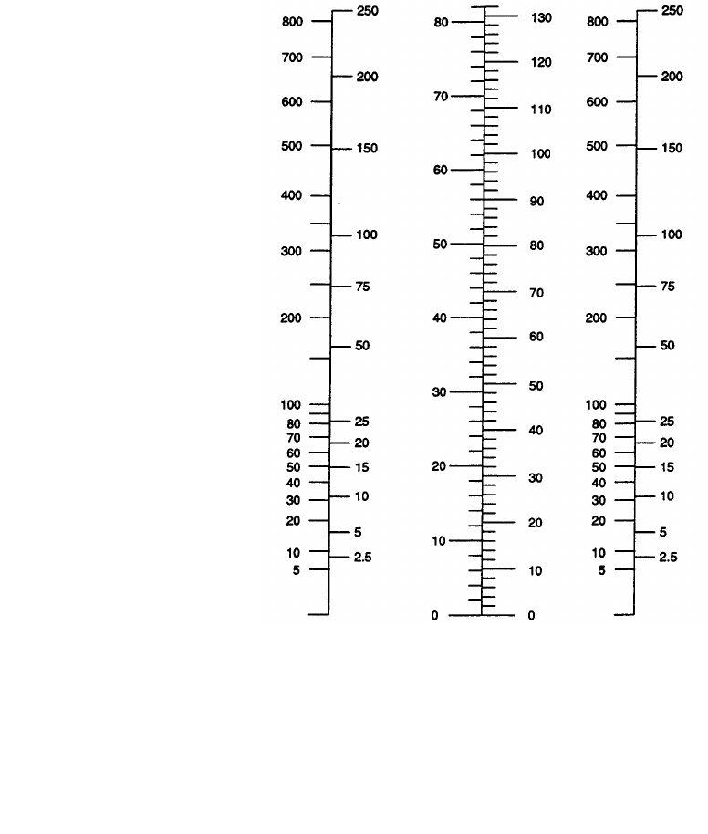
78 Chapter 5 Installation Planning
•
•
•
•
•
•
A reasonable approximation of the radio horizon (line-of-sight) based on
antenna height is shown in Figure 5-1. On the chart, set a straight-edge so
that it crosses the height of one antenna in the column on the left and the
height of the other antenna in the column on the right; the radio horizon in
miles or kilometers is shown where the straight-edge crosses the center
column.
Figure 5-1 Antenna height chart
*Path length for grazing clearance over flat terrain without trees or other
obstructions.
ANTENNA1 HEIGHT ANTENNA2 HEIGHT2 X RADIO HORIZON*
(feet (miles (feetmeters) meters)km)

Aurora 5800
79
•
•
•
•
•
•
Antenna Cable Selection
Harris recommends low-loss and low-cost RF cables to connect the radio to
the antenna. Andrew’s LDF4-50A coaxial cable is standard with the Aurora
5800 radio. See Table 5-1 for cable characteristics.
Table 5-1 LDF4-50A cable parameters
Characteristic Value
Cable Part Number LDF4-50A
Nominal Size (in.) 1/2
Impedance (ohms) 50
Approx. Atten, at 5.8 GHz
dB/100 ft (dB/100 m) 6.5 (21)
Weight, lb/ft (kg/m) 0.15 (0.22)
Diameter over Jacket,
in. (mm) 0.63 (16)
Min. Bending Radius,
in. (mm) 5 (125)

80 Chapter 5 Installation Planning
•
•
•
•
•
•
Antenna Alignment
The antenna can be aligned by monitoring the RSSI test jack. Use a digital
multimeter to measure the RSSI voltage when adjusting the direction of the
antenna. The RSSI level of 0 to 4.8 VDC corresponds to the receiver input
level of approximately -90 to -20 dBm. See
Table 5-2
.
Typical RSSI Voltage versus Receiver Input Level
Table 5-2 Typical RSSI voltage versus receiver input level
RX Input Level
(dBm) RSSI Voltage
(V)
−
90
−
0.05
−
85 0.69
−
80 1.34
−
75 1.83
−
70 2.30
−
65 2.67
−
60 3.01
−
55 3.28
−
50 3.54
−
45 3.77
−
40 4.00
−
35 4.20
−
30 4.39
−
25 4.58
−
20 4.75

Aurora 5800
81
•
•
•
•
•
•
Point-to-Point Path Analysis
Programs that allow you to perform path analysis are available from several
vendors. In any case, the following steps should be followed.
1.
Plot the location of each antenna on a topographical site map.
2.
Draw lines showing the radio path between sites.
3.
On a graph paper, plot the distance (horizontal axis, in miles or
kilometers) versus the ground elevation (vertical axis, in feet or
meters).
4.
Identify all obstructions on the radio path line on the map, including
hills, vegetation, and buildings or structures that will interfere with
radio transmission.
5.
Plot each obstruction on the graph by marking the elevation and
distance from the sites.
6.
For each obstruction, compute the increment to the height of each
obstruction to allow for the earth’s curvature.
where
h1 = additional height increment in feet or meters,
d1 = distance of obstruction from site in miles or
kilometers,
d2 = distance of the obstruction from the second site in
miles or kilometers,
C= 1.5 for English units or 12.75 for metric units, and
k= a refractive index of 1.33 for both English and metric
units.
Add the additional height increment, h1, to the elevations plotted on
your graph.
h1 d1 d2×
Ck
-------------------
=

82 Chapter 5 Installation Planning
•
•
•
•
•
•
7.
Compute another increment to the height of each obstruction for the
Fresnel zone.
where
h2 = 60% of the first Fresnel zone in feet or meter,
C= 43.26 for English or 10.38 for metric units,
d1 = the distance of the obstruction from the first site in
miles or kilometers,
d2 = the distance of the obstruction from the second site in
miles or kilometers,
f= 5.8 GHz in English or metric units, and
D= total path length (d1 + d2) in miles or kilometers.
Add the h2 increment to the elevations on the graph.
8.
Determine the ideal antenna height by drawing a line on the graph
between the sites and across the top of the obstruction heights.
Note the elevation of each antenna site.
9.
Use the following formula to determine the free-space path.
where
L= the path loss in dB,
C= 96.6 for English units (distance in miles) and
92.4 for metric units (distance in kilometers),
D= distance in miles or kilometers, and
f= the signal frequency (5.8 GHz for both English and
metric units for the Aurora radio).
For example, for a 15-mile path, path loss
h2 C d1 d2×
fD×
-------------------=
LC20 D()log 20 f()log++=

Aurora 5800
83
•
•
•
•
•
•
= 96.6 + 20 log 15 + 20 log 5.8 GHz = 136 dB.
For a 15-km path, path loss
= 92.4 + 20 log 15 + 20 log 5.8 GHz = 131 dB.
10.
Calculate the unfaded Received Signal Level (RSL).
RSL= TX Power + TX Antenna Gain − Coax Loss
− Free Space Loss + RX Antenna Gain
− Coax Loss
For example, if the TX Power is +19 dBm, the Coax Loss is 2 dB for
the TX and 2 dB for the RX, the Antenna Gain is 28 dBi for the TX
and 28 dBi for the RX, and the Path Loss is 136 dB, then
RSL= +19 dBm + 28 dBi − 2 dB − 136 dB + 28 dBi
− 2 dB
= − 65 dBm
11.
Calculate the Fade Margin (FM)
FM = RSL − Receiver Sensitivity at 10-3 BER (outage)
FM = −65 − (−90) = 25 dB.

84 Chapter 5 Installation Planning
•
•
•
•
•
•
Examples of Transmission Distances
Table 5-3 lists some examples of the FCC-compliant Aurora 5800 possible
transmission distances for different antennas and different transmit output
powers.
Table 5-3 Examples of maximum free-space transmission distance
Assumption: 32.8 ft (10 m) LDF4-50A cable feed for both antennas and
25 dB fade margin for BER 10-6/10-3
.
Notes
:
1. 32.8 ft (10 m) LDF4-50A cable loss approximately 2 dB.
2. Typical T1/E1 Aurora receiver threshold, −88 dBm at BER 10-6 (static
threshold) and −90 dBm at BER 10-3 (outage threshold).
3. Free-space, path-loss calculation:
L = C + 20 log (D) + 20 log (f).
L= the path loss in dB.
C= 96.6 for distance in miles and 92.4 for distance in
kilometers.
D= distance in miles or kilometers.
f= the signal frequency in MHz.
For example, for
output power = 19 dBm,
antenna gain = 28 dBi,
TX antenna cable loss = 2 dB,
Antenna
Gain
(dBi)
Transmit Output Power
(+19 dBm)
EIRP
(dBm)
Transmission
Distance (miles/km)
BER 10
-6
/10
-3
28 45 13/15
28.5 45.5 14/18
31.4 48.4 28/35
34.8 51.8 61/77

Aurora 5800
85
•
•
•
•
•
•
the TX EIRP = 19 + 28 − 2 = 45 dBm.
The receiver antenna net gain = 28 − 2 (cable loss) = 26 dB;
hence the total path loss with this radio system =
45 + 26 + 90 − 25 (required fade margin) = 136 dB,
that corresponds to a free-space distance of about 15 miles. With 23
dB (2 dB less) fade margin for a 10-6 BER static point, this distance
reduces to 13 miles.
If the actual transmission distance is reduced to 10 miles, the path loss
is about 132 dB; then the system has about 27-dB fade margin for
BER 10-6 and 29-dB fade margin for BER 10-3.
Spacing Requirement
If the Aurora radio is being installed in an equipment rack, leave one rack
space above the radio and one rack space below the radio.

86 Chapter 5 Installation Planning
•
•
•
•
•
•
This page intentionally blank.

Aurora 5800
87
•
•
•
•
•
•
Chapter 6
• • • • • •
Software Utility Program
Aurora Software
The Aurora 5800 is shipped with a diskette containing a utility program,
AURORA5800
, that is used to configure the radio for proper operation. The
utility can also be used to monitor the built-in alarms and status indicators.
Installing the Software
The
AURORA5800
utility program can be installed and executed on any PC
running the Microsoft Windows 95, 98, or NT 4.0 operating system. To
install the software, do the following:
1.
Insert AURORA5800
Setup Disk 1
in the computer’s disk drive
(usually drive
A
:).
2.
From the Windows or NT
Start
menu, select
Settings
Control Panel
Add/Remove Programs.
The setup program guides you through the install process, and you
can select which directory you want the
AURORA5800
installed.

88 Chapter 6 Software Utility Program
•
•
•
•
•
•
Running the Software
Once it is installed, you can run the
AURORA5800
program by
1.
clicking on the
Start
button and
2.
choosing
Programs
from the
Start
menu and then
3.
choosing
AURORA5800
from the submenu.
AURORA5800 Main Window
A few moments after you start
AURORA5800
, the main window
(
Figure 6-1
) appears.
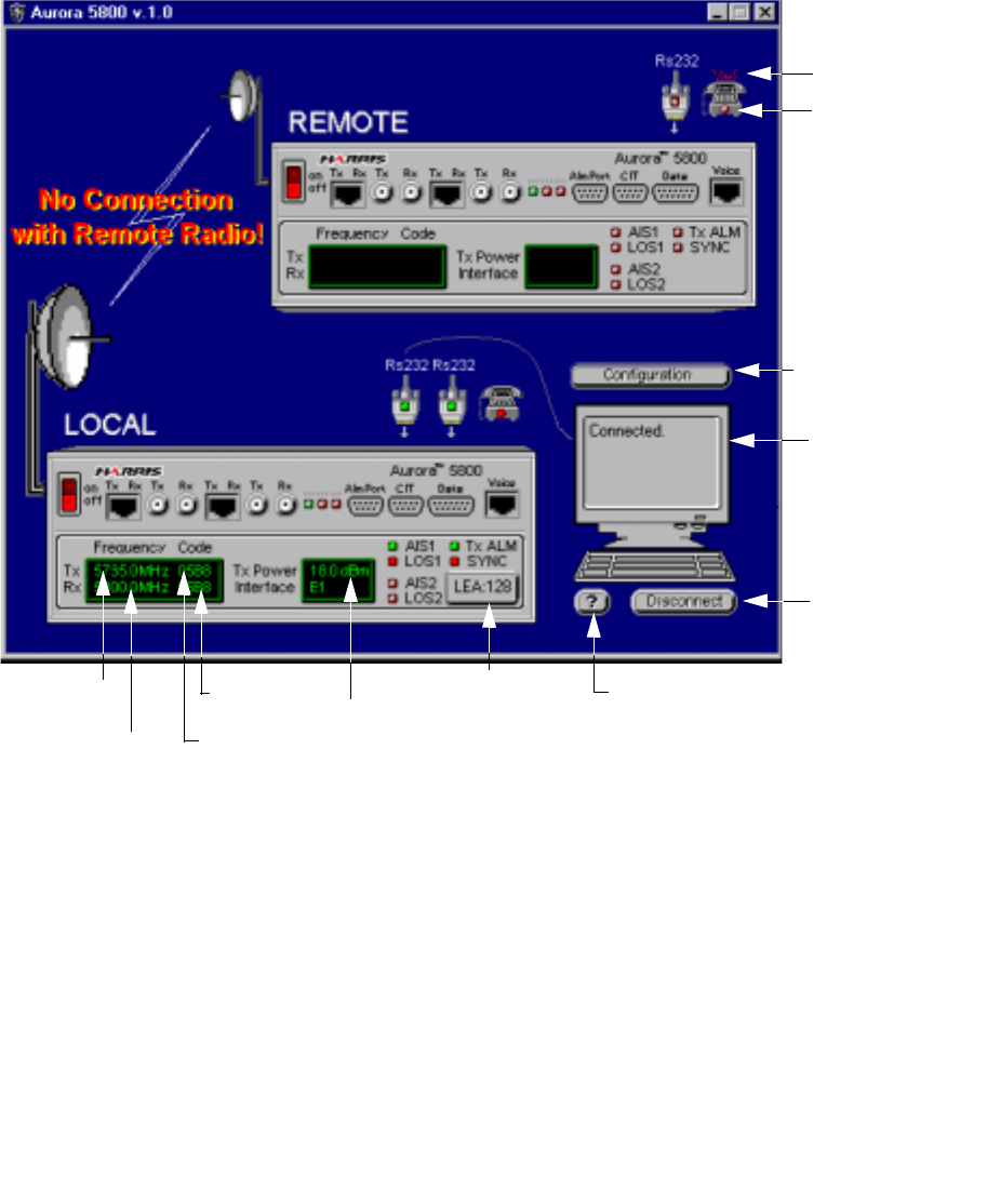
Aurora 5800
89
•
•
•
•
•
•
Figure 6-1 AURORA5800 main window
Features
From the main window, you can
•Make selections to set the transmit and receive frequencies.
•Define the spread code.
•Adjust the Tx output power.
•Save connection configurations.
•Monitor the radio’s alarms/status levels.
•See the latest transmit/receive frequencies and PN spread codes.
Connect
button
Configuration
button
Tx Frequency
button Rx Sequence
Code button
Rx Frequency button
Help button
Tx Power button
Tx Sequence Code button
Message
box
Ring-on
state
Voice
indicator
Local equipment
address

90 Chapter 6 Software Utility Program
•
•
•
•
•
•
Status/Alarms
Six status and alarm conditions are monitored and displayed on the
AURORA5800
main window.
Table 6-1 Alarms
Green indicates that everything is running okay. Red indicates an alarm
condition.
Phone
The green light on the phone icon indicates a voice connection. A red splash
above the phone indicates a ring-on state.
Alarm
Designation Color Status
LOS1
LOS2 Green No loss of signal.
Red Receiver loss of signal when either
receiving 175 consecutive zeros or
received signal amplitude drops below 0.3 V peak threshold.
AIS1
AIS2 Green Normal.
Red Unframed all one’s is detected (criteria of less than three zeros
out at 2048-bit period).
Tx ALM Green Transmit power is above threshold level (okay).
Red Transmit power has dropped below a preset threshold level.
SYNC Green Traffic is normal.
Red Synchronization alarm.
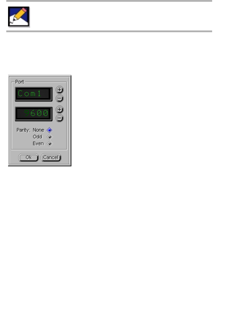
Aurora 5800
91
•
•
•
•
•
•
Connection Configuration
From the main window (
Figure 6-1
), click the
Configuration
button. The
Connection Configuration dialog box appears.
Figure 6-2 Connection Configuration dialog box
1.
To select the COM Port the Aurora 5800 radio is connected to, click
the
+
or
−
button.
2.
To select the bit rate for the selected COM Port, click the
+
or
−
button.
3.
To change the parity, click the appropriate button.
4.
Click the
Ok
button to save the changes in “aurora.cfg” file.
If FarScan is locally connected to the Aurora 5800 radio’s
CIT port, then you must select 9600 b/s and no parity.

92 Chapter 6 Software Utility Program
•
•
•
•
•
•
Connecting the COMM Port
The RS-232 user interface connector is on the front panel of the Aurora
radio.
1.
From the main window (Figure 6-1) double-click the
Connect
button at the lower right-hand side.
2.
The AURORA5800 searches the selected comm port that is
connected to the radio. A message “connecting over COMx . . .”
appears.
3.
When the radio is detected at that Comm port, the word “Connected”
appears in the message box.
4.
The main window displays the radio default configuration
parameters.
T1/E1 interface
Tx and Rx Spread Sequence
Tx and Rx RF Frequency
Tx Output Power level
Alarms
The
Connect
button changes to
Disconnect
.
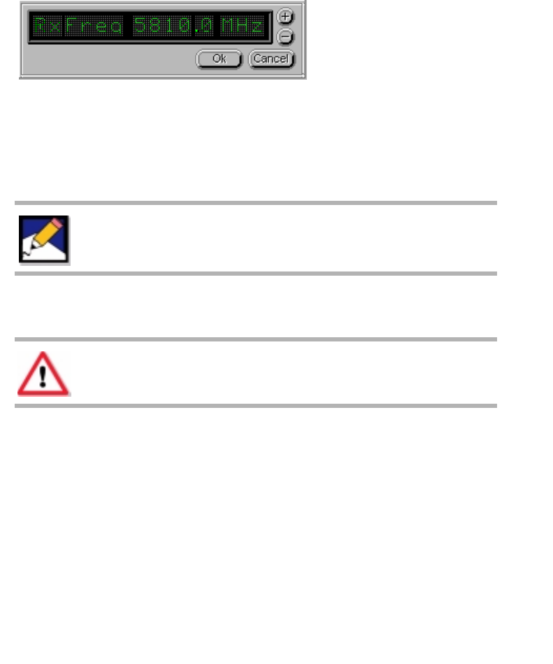
Aurora 5800
93
•
•
•
•
•
•
Frequency
From the main window (
Figure 6-1
), click on the
Tx
or the
Rx Frequency
button. The Set Frequency dialog box appears.
Figure 6-3
is an example of
a
Set Rx Frequency
dialog box.
Figure 6-3 Set Rx Frequency dialog box
1.
To change the frequency, click the
+
or
−
button.
2.
When the desired frequency appears, click the
Ok
button.
If the frequency is changed, ensure that the corresponding frequency at the
far end is changed also.
Small adjustments are possible. Frequency can be
adjusted up to 500 kHz away from the nominal
channel plan.
If the selected frequency is not the same as the frequency
displayed on the label, the radio does not function correctly.
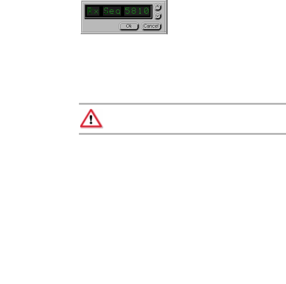
94 Chapter 6 Software Utility Program
•
•
•
•
•
•
Spread Code
From the main window (
Figure 6-1
), click on the
Tx
or the
Rx Sequence
code button. The Set Sequence dialog box appears.
Figure 6-4
is an
example of the
Set Rx Sequence
dialog box.
Figure 6-4 Set Rx Sequence dialog box
There are 4 preset codes to choose from.
1.
To change the code, click the
∧
or
∨
button.
2.
When the desired code appears, click the
Ok
button to download the
new value.
Tx Output Power
From the main window (
Figure 6-1
), click on the
Tx Power Interface
button. The
Tx Power Settings
dialog box (
Figure 6-5
) appears.
Ensure that the Transmit Code at the far end is the same
as the Receive Code at the near end. Otherwise, the radio
link does not operate properly.

Aurora 5800
95
•
•
•
•
•
•
Figure 6-5 Tx Power Settings dialog box
Set Alarm Level
1.
Use an RF Power Meter to monitor the actual power at the antenna
port.
2.
Click the big
+
and
−
buttons at the top of the dialog box to set the
desired alarm power level.
The alarm level may be 3 dB below the output level.
3.
Click the
Set alarm level
button to save this setting.
Set Power
4.
Click the big
+
and
−
buttons at the top of the dialog box to set the
nominal power level.
Tx Power Display
5.
Click the small
+
and
−
buttons at the bottom right-hand side of the
dialog box to display the nominal power level.
6.
Click the
Set Power
button to save this setting.
This setting is displayed as a reminder only. This feature does not
track the actual power level.
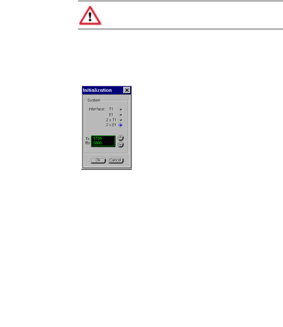
96 Chapter 6 Software Utility Program
•
•
•
•
•
•
Init Hardware
1.
Right-click the mouse.
2.
Choose
Init
. The Initialization dialog box (Figure 6-6) appears.
Figure 6-6 Initialization dialog box
3.
Select
Interface
type.
4.
Click the up and down buttons to select the nominal radio frequency
pairs.
Refer to the frequencies shown on the back label.
5.
Click the
Ok
button to set the new values and start the initialization
procedure.
Quitting the AURORA5800 Program
To quit the program, from the main window click the
X
in the upper right-
hand corner.
This dialog box is available only to the professional
installer.

Aurora 5800
97
•
•
•
•
•
•
Chapter 7
• • • • • •
Troubleshooting Guideline
General
This guideline is offered in troubleshooting the Aurora radio in the unlikely
event a trouble occurs. This guideline is intended for new installations only.
Always check the radio pairs on a bench before field installation. To perform
the bench test, use:
•0-dBi omni antennas
or
•Cables with a coaxial 60-dB attenuator.
Once the radio is installed, normal operation is indicated by the following
conditions:
•The green PWR LED is on.
•The red TX ALM and RX ALM LEDs are off.
•The RSSI level is between 0 and 4.8 VDC.
Call the Harris Customer Resource Center if the trouble is
not resolved.

98 Chapter 7 Troubleshooting Guideline
•
•
•
•
•
•
Power LED Off
If no communication link is achieved, and if the PWR LED (green) is off:
•Check the power switch on the left front panel of the radio.
•Check the connections to the power source.
•Check the power source itself for availability of power.
TX Power Alarm
If the TX ALM LED (red) is on:
•The transmit output power level may be too low (3 dB lower than
nominal).
Use the
AURORA5800
software program to check the power level.
RX Data Alarm
If the RX ALM LED (red) is on:
•There may be a problem in the receive path resulting in a low received
signal level, or
•The far-end transmitter output power is too low or off, or
•There may be a problem with the antenna connection
or alignment.
Check the receiver’s RSSI voltage level with a DMM.
•Level should be between 0 and 4.8 VDC.
•If the level is too low (closer to 0 VDC), the antenna may not be properly
aligned. Adjust the antenna direction to increase RSSI reading. Check the
coaxial cable connections.

Aurora 5800
99
•
•
•
•
•
•
If the RSSI level cannot be improved with antenna adjustment, the remote
site transmitter may have a Tx Power alarm.
•Go to the remote site and check and correct the transmitter’s output
power level.
Software Diagnosis
If the LEDs and RSSI are normal but still no communication link can be
established, use the Aurora 5800 utility software to troubleshoot the
problem. The software’s diagnostics provides additional information about
the receive and transmit synthesizers, and the status of the LOS and AIS for
the digital interface.
If the synthesizer has failed or if there is an LOS or AIS alarm, then the radio
does not operate normally. In addition, ensure that the radio pairs are
configured correctly by re-downloading the receive and transmit
synthesizer frequencies and the spread sequence into the radio processor,
and then reset the radio transmit power to nominal levels. See the back label
for frequency-pair information.
LOS Alarm
Loss of Signal (LOS) means the DS-1/E1 signal is missing at the input of
the modem board.

100 Chapter 7 Troubleshooting Guideline
•
•
•
•
•
•
Interference Resolution
If, after the link is installed, too many path errors are indicated on the T1 or
E1 test set, a potential interference problem may exist. Try the following
corrective steps.
1.
Rotate the antenna direction slightly, and see if there is an
improvement in the BER.
2.
If no improvement is achieved, rotate the polarization of the antenna
at both ends of the link by 90
o
.
3.
If still no improvement is achieved after 2., use the SSRadio
software utility program to change the Transmitter and Receiver
Spread Sequence.
The software provides four different PNs. Use a PN other than the
currently installed one, and check for improvement. Make sure the
Transmitter Spread Sequence at one end is the same as the
Receiver Spread Sequence at the opposite end. Harris
recommends that you use different transmit and receive codes
within the same radio to minimize the transmit power leakage into
the receiver.
4.
If no obvious improvement is achieved from the preceding steps,
use the SSRadio software and make a slight adjustment to either
the transmit or receive synthesizer frequency, or both.
•Do not make an adjustment of more than
±
500 kHz from the
nominal channel plan (to avoid operating outside of the diplexer
filters’ passband).
•Ensure that the transmit frequency at one end matches the
receive frequency at the opposite end.

Aurora 5800
101
•
•
•
•
•
•
Chapter 8
• • • • • •
Connecting to FarScan
Introduction
FarScan is a computer-based network supervision system that runs in
Microsoft Windows.
FarScan performs five primary functions:
•Manual command execution
•Polling (AutoPoll and SelectPoll)
•Equipment activity logging
•FarScan networking
•Paging

102 Chapter 8 Connecting to FarScan
•
•
•
•
•
•
Hardware Interface
The FarScan computer can be connected to the Harris radio network locally,
or remotely by using standard modems connected to a telephone line.
Hardwire Connection
Aurora 5800 radio can be connected to FarScan locally by using the FarScan
interface cable.
The cable (Harris part number 087-108906-025) is connected to the CIT
port on the Aurora 5800 radio. Refer to
Chapter 2
for more information on
the CIT port.
Modem Connection
A null modem cable is connected to the DATA port (15-pin) on the Aurora
5800 radio. Refer to Chapter 2 for more information on the DATA port.
Software Interface
Refer to
Chapter 6
for instructions on how to connect the COMM port.
For More Information
Refer to the
FarScan for Windows Instruction Manual
for more information.

Aurora 5800
103
•
•
•
•
•
•
Chapter 9
• • • • • •
Customer Service and Warranty Information
Warranty and Product Support
Warranty and product support information is provided at the time of
purchase with the sales invoice and other sales documents. Read the
warranty information on
page 108
for the equipment or assembly before
contacting the Microwave Communications Division (MCD) Customer
Service.

104 Chapter 9 Customer Service and Warranty Information
•
•
•
•
•
•
Ordering Spares
Harris MCD Aurora 5800 is designed to be repaired at the shelf level. For
this reason, parts lists are not furnished with an order, nor are they available.
All orders must be at the top radio shelf level for a complete unit. Make all
inquiries for spare radios to the Spare Products Support Center at the
following address.
Repair and Return
Harris MCD repairs all its manufactured products as well as coordinates
repairs on vendor items that are part of its systems. The standard repair
turnaround time for current models of some products is 5 working days upon
receipt of the defective parts. Repair turnaround time for other products is
15 working days. Discontinued items repair turnaround is subject to the
availability of spares.
Emergency repair is available with a 24-hour turnaround time for current
production models of some products and 48 hours for other products.
Turnaround time for Manufacturing Discontinued items is subject to the
nature of the problems. Emergency repairs are billed at actual repair price
Harris Microwave Communications Division
Spare Products Support Center
3, Hotel de Ville
Dollard-des-Ormeaux, Quebec
CANADA H9B 3G4
Tel: 1-800-227-8332 (U.S.A.)
1-800-465-4654 (Canada)
(+1) 514-421-8333
Fax: (+1) 514-421-3555
The Customer Resource Center is now available on the
worldwide web at
http://www.microwave.harris.com/cservice/.

Aurora 5800
105
•
•
•
•
•
•
(zero for warranty units) plus some surcharge per radio. Our normal
shipping time is 4 P.M. (Central Time) unless special shipping instruction is
requested.
Repair charges and turnaround time for OEM (vendor) items are set by
Harris MCD suppliers. Our close working relationships with our suppliers
assure us of the best repair prices and turnaround time. Repair charges are
billed at supplier’s cost plus the necessary handling fee.
Module Exchange
You may prefer to receive a replacement radio before you send your
defective unit to us. Harris MCD maintains an inventory of many different
configurations that can be shipped to you within 24 hours. Radios that
require retuning or reconfiguring can be shipped within 48 hours.
All exchanged radios must be returned to us within 15 days to avoid getting
invoiced for the difference between the exchange price and the list price.
Evaluation Fee
There is an evaluation charge per unit if no trouble is found and no repair is
required.
Unrepairable Units
Equipment that has been damaged because of customer negligence or that
has parts removed will be repaired at the prevailing flat repair fee, or on a
time-and-material basis, whichever is higher and regardless of the warranty
status. Any equipment that is determined to be unrepairable will be returned
to the customer. An evaluation fee will be assessed. This fee will be
refunded if the customer purchases a replacement radio within 30 days.

106 Chapter 9 Customer Service and Warranty Information
•
•
•
•
•
•
Return Freight
Harris MCD prepays standard return freight back to our customers on
warranty repairs. Return freight back to customers on billable repairs is
invoiced to the customers. The customer pays for shipping units to Harris
MCD for both warranty and out-of-warranty repairs. Special shipping
requests may be subject to additional charge.
All shipments outside the continental USA and Canada are subject to
additional handling charge per shipment.
Please pack the unit carefully using static-free, sturdy packaging to prevent
damage during transit.
Return Material Authorization
Before sending in your equipment for repair, first contact the Harris MCD
and request a return material authorization (RMA) number. Obtaining an
RMA number insures you that the repairs will be done in a timely manner
and prevents any delays due to incomplete information.
Please provide the following information:
1. Your name, company, and telephone number.
2. Equipment type, part number, and sales order number (labeled on back
of shelf).
3. Detailed description of the problem.
4. Purchase order number.
5. Billing and shipping addresses.
6. Any special return packing or shipping instructions.
7. If required, customs clearance information.

Aurora 5800
107
•
•
•
•
•
•
Repair Telephone and Fax Numbers
U.S.A. and Canada
Repair Service Locations
When you receive the RMA number, the Harris MCD customer service
representative will instruct you to ship your defective unit(s) to one of the
following addresses.
U.S.A.
Canada
Tel: 1-800-227-8332
(U.S.A. only)
1-800-465-4654
(Canada only)
(+1) 514-421-8333
Fax: (+1) 514-421-3555
Harris Microwave Communications Division
Attn: Customer Service, RMA #_ _ _ _ _
5727 Farinon Drive
San Antonio, TX 78249
Harris Microwave Communications Division
Attn: Customer Service, RMA #_ _ _ _ _
3, Hotel de Ville
Dollard-des-Ormeaux, Quebec
CANADA H9B 3G4

108 Chapter 9 Customer Service and Warranty Information
•
•
•
•
•
•
Customer Training
Harris MCD offers courses in microwave, lightwave, and multiplex system
operation designed to maximize product performance and minimize
maintenance costs. Regular classes are held in our Redwood Shores,
California, and Montreal, Canada facilities. Special classes can be held at
customer sites. Training is available for standard products. All other training
requirements must be quoted by the Customer Training Department. For
information call 1-800-227-8332 or 1-800-465-4654.
Standard Product Warranty Terms
Harris MCD warrants that each product of its own manufacture shall, at the
time of delivery and for a period of 24 months thereafter, be free from
defects in materials and workmanship. For such products that are installed
by Harris MCD, this warranty shall extend for 18 months from date of
installation, provided that the time from the date of delivery to the date of
installation does not exceed 6 months. Such warranty shall not include any
consumable components to which a specific manufacturer’s guarantee
applies. If any Harris MCD product shall prove to be defective in materials
or workmanship under normal intended usage, operation, and maintenance
during the applicable warranty period as determined by Harris MCD after
examination of the product claimed to be defective, then Harris MCD shall
repair or replace, at Harris MCD’s sole option, such defective product, in
accordance with procedures specified below, at its own expense, exclusive,
however, of the cost of labor by the customer’s own employees, agents or
contractors in identifying, removing or replacing the defective part(s) of
the product.
In composite equipment assemblies and systems, which include equipment
of such other than Harris MCD manufacture, Harris MCD’s responsibility
under this warranty provision for the non-Harris MCD manufactured
portion of the equipment shall be limited to the other equipment
manufacturer’s standard warranty. Provided, however, that if the other
manufacturer’s standard warranty period is of a shorter duration than the
warranty period applicable to Harris MCD’s manufactured equipment, then
Harris MCD shall extend additional coverage to such other equipment

Aurora 5800
109
•
•
•
•
•
•
manufacturer’s warranty equal to the differential in time between the
expiration of the other manufacturer’s warranty and the duration of Harris
MCD’s manufactured equipment warranty applicable to such order. Harris
MCD shall repair or replace, at Harris MCD’s sole option, such other
manufacturer’s defective part(s) within 60 days after receipt of such parts by
Harris MCD in accordance with the below specified procedures, at Harris
MCD’s own expense, exclusive, however, of cost of labor by the customer’s
own employees, agents or contractors in identifying, removing or replacing
the defective part(s) of the product.
An authorization to return products to Harris MCD under this warranty must
be obtained from a Harris MCD representative prior to making shipment to
Harris MCD’s plant, and all returns shall be shipped freight prepaid. Collect
shipments will not be accepted, but Harris MCD will prepay return freight
charges on repaired and replaced products found to be actually defective.
Liability of Harris MCD for breach of any and all warranties hereunder is
expressly limited to the repair or replacement of defective products as set
forth in this section, and in no event shall Harris MCD be liable for special,
incidental or consequential damages by reason of any breach of warranty or
defect in materials or workmanship. Harris MCD shall not be responsible
for repair or replacement of products that have been subjected to neglect,
accident or improper use, or that have been altered by other than authorized
Harris MCD personnel.
Any warranties or conditions made herein by Harris are exclusive, made in
lieu of all other warranties or conditions, express or implied (except to title)
including, but not limited to, any implied warranty or condition of
merchantability, any implied warranty or condition of fitness for a particular
purpose, or any warranty or condition arising out of performance or custom
or usage of trade. Customer acknowledges any circumstances causing any
such exclusive or limited remedy to fail of its essential purpose shall not
affect any Harris warranty.

110 Chapter 9 Customer Service and Warranty Information
•
•
•
•
•
•
Limitation of Damages
Harris’ total and maximum liability under this agreement or in connection
with the subject matter of this agreement or any transaction related to this
agreement, shall be limited to one-half (1/2) of the aggregate amount paid
to Harris, regardless of the basis for such liability. Customer acknowledges
and agrees this section shall be enforceable in the event of any claim made
in connection with this agreement, including, but not limited to, any claim
for failure of delivery. In no event shall Harris be liable for any punitive,
special, incidental, or consequential damages, including, but not limited to
lost profits, opportunities or savings or for any loss of use of, or loss of data
or information of any kind, however caused or for any full or partial loss of
performance of any product, even if Harris has been advised of the
possibility of such damages.

Aurora 5800
111
•
•
•
•
•
•
Appendix A
• • • • • •
Transmit or Receive RF Filter Responses
This appendix includes actual results from laboratory tests.
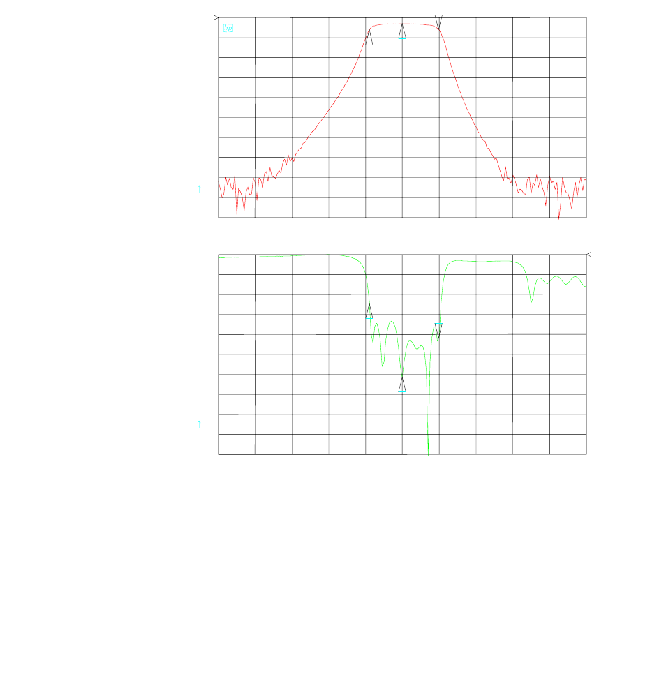
112 Appendix A Transmit or Receive RF Filter Responses
•
•
•
•
•
•
T1/E1 Diplexers
The RF filter response graphs are shown in Figure A-1 through Figure A-6.
Figure A-1 Filter with center frequency of 5.735 GHz
CH1 S21 log MAG 10 dB/ REF 0 dB
CH2 S11 log MAG REF 0 dB5 dB/
CENTER 5 735.000 000 MHz SPAN 150.000 000 MHz
1
2
3
3_ -5.9761 dB
5 749.820 000 MHz
1_ -2.9798 dB
5.735 GHz
2_ -6.003 dB
5.721 GHz
1
23
3_:-20.845 dB
5 749.820 000 MHz
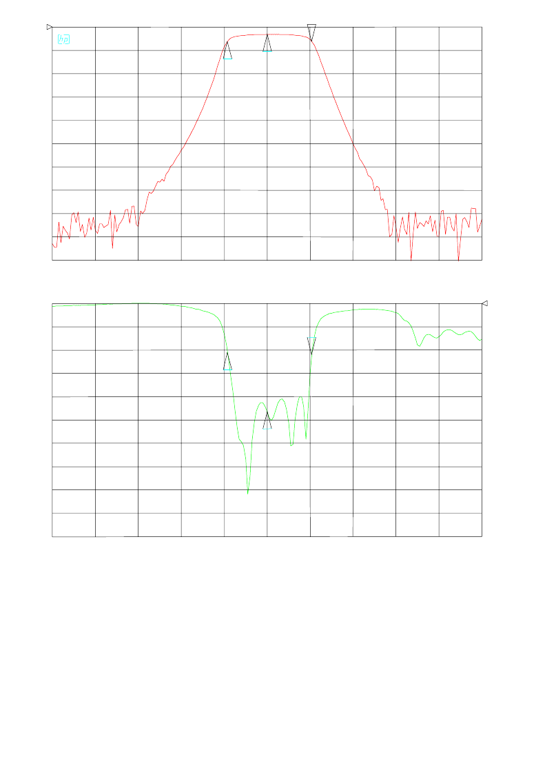
Aurora 5800
113
•
•
•
•
•
•
Figure A-2 Filter with center frequency of 5.755 GHz
CH1 S21 log MAG 10 dB/ REF 0 dB
CH2 S11 log MAG REF 0 dB5 dB/
CENTER 5 755.000 000 MHz SPAN 150.000 000 MHz
1
2
3
3_ -6.1175 dB
5 770.585 001 MHz
1_ -3.1119 dB
5.755 GHz
2_ -6.1371 dB
5.741 GHz
1
2
3
3_:-10.945 dB
5 770.585 001 MHz
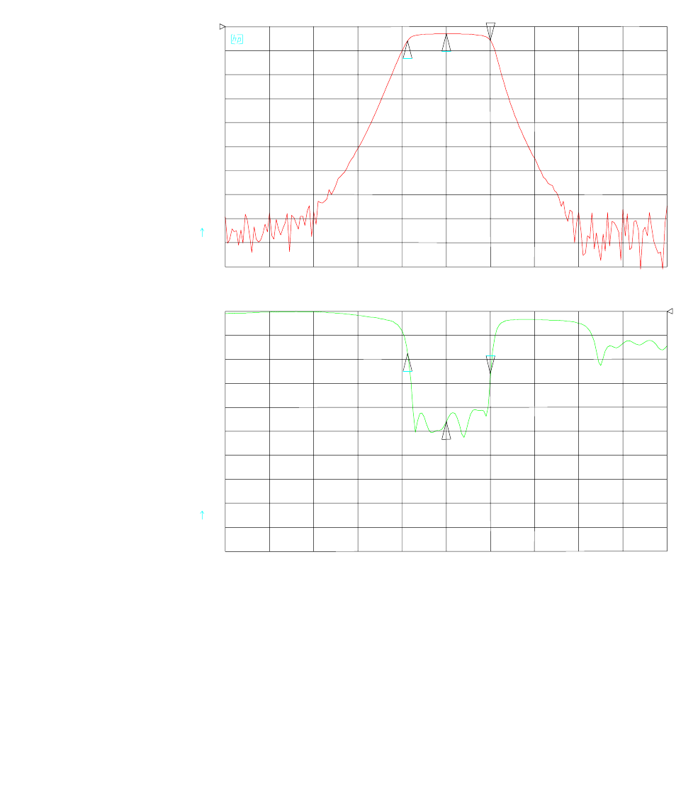
114 Appendix A Transmit or Receive RF Filter Responses
•
•
•
•
•
•
Figure A-3 Filter with center frequency of 5.775 GHz
CH1 S21 log MAG 10 dB/ REF 0 dB
CH2 S11 log MAG REF 0 dB5 dB/
CENTER 5 775.000 000 MHz SPAN 150.000 000 MHz
1
2
3
3_ -5.7667 dB
5 790.050 002 MHz
1_ -2.7971 dB
5.775 GHz
2_ -5.8321 dB
5.761 GHz
1
2
3
3_:-12.904 dB
5 790.050 002 MHz
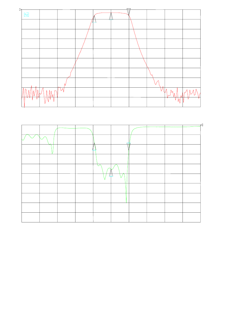
Aurora 5800
115
•
•
•
•
•
•
Figure A-4 Filter with center frequency of 5.8 GHz
CH1 S21 log MAG 10 dB/ REF 0 dB
CH2 S11 log MAG REF 0 dB5 dB/
CENTER 5 800.000 000 MHz SPAN 150.000 000 MHz
1
2
3
3_ -5.991 dB
5 814.845 001 MHz
1_ -3.0377 dB
5.800 GHz
2_ -6.01 dB
5.785 GHz
1
2
3
3_:-12.909 dB
5 814.845 001 MHz
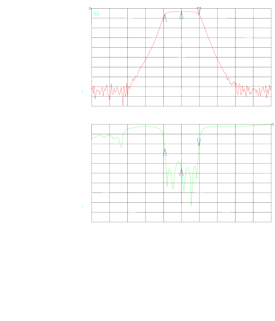
116 Appendix A Transmit or Receive RF Filter Responses
•
•
•
•
•
•
Figure A-5 Filter with center frequency of 5.82 GHz
CH1 S21 log MAG 10 dB/ REF 0 dB
CH2 S11 log MAG REF 0 dB5 dB/
CENTER 5 820.000 000 MHz SPAN 150.000 000 MHz
1
2
3
3_ -6.2021 dB
5 834.635 003 MHz
1_ -3.2001 dB
5.82 GHz
2_ -6.2019 dB
5.806 GHz
1
2
3
3_:-10.913 dB
5 834.635 003 MHz
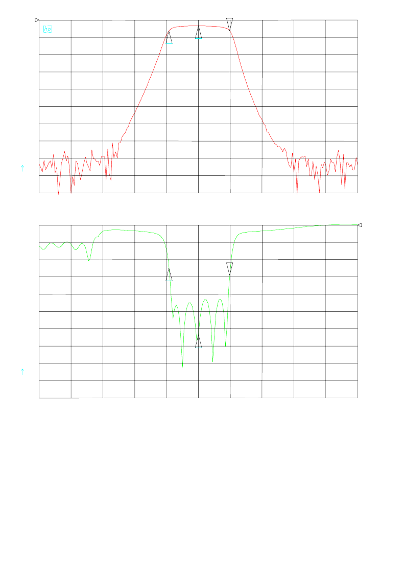
Aurora 5800
117
•
•
•
•
•
•
Figure A-6 Filter with center frequency of 5.84 GHz
CH1 S21 log MAG 10 dB/ REF 0 dB
CH2 S11 log MAG REF 0 dB5 dB/
CENTER 5 840.000 000 MHz SPAN 150.000 000 MHz
1
2
3
3_ -6.241 dB
5 854.760 002 MHz
1_ -3.2412 dB
5.840 GHz
2_ -6.1996 dB
5.826 GHz
1
2
3
3_:-14.527 dB
5 854.760 002 MHz
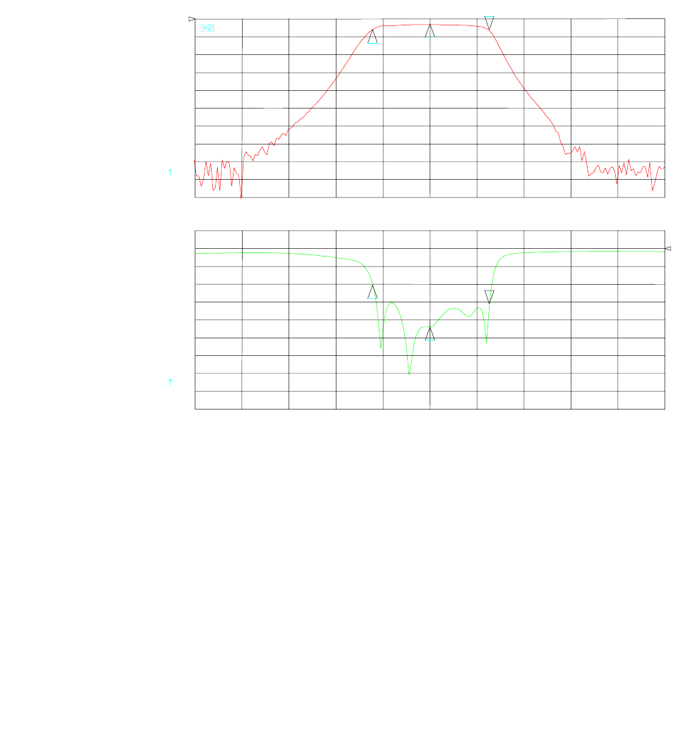
118 Appendix A Transmit or Receive RF Filter Responses
•
•
•
•
•
•
2T1/2E1 Diplexers
Figure A-7 Filter with center frequency of 5.741 GHz
CH1 B/R log MAG 10 dB/ REF 0 dB
CH2 S 11 log MAG REF 0 dB5 dB/
CENTER 5 741.000 000 MHz
SPAN 150.000 000 MHz
12
33_ -5.8986 dB
5 760.005 002 MHz
1_ -5.8924 dB
5.722 GHz
2_ -2.8476 dB
5.741 GHz
1
2
3
3_:-15.435 dB
5 760.005 002 MHz
1_:-10.233 dB
5.722 GHz
2_:-22.014 dB
5.741 GHz
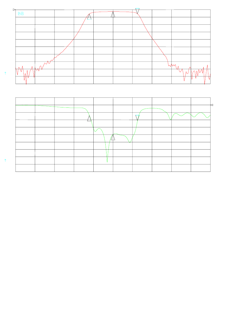
Aurora 5800
119
•
•
•
•
•
•
Figure A-8 Filter with center frequency of 5.772 GHz
CH1 B/R log MAG 10 dB/ REF 0 dB
CH2 S 11 log MAG REF 0 dB5 dB/
CENTER 5 772.000 000 MHz
SPAN 150.120 000 MHz
12
33_ -5.6245 dB
5 790.915 120 MHz
1_ -5.6025 dB
5.753 GHz
2_ -2.605 dB
5.772 GHz
1
2
3
3_:-10.493 dB
5 790.915 120 MHz
1_:-7.135 dB
5.753 GHz
2_:-19.927 dB
5.772 GHz
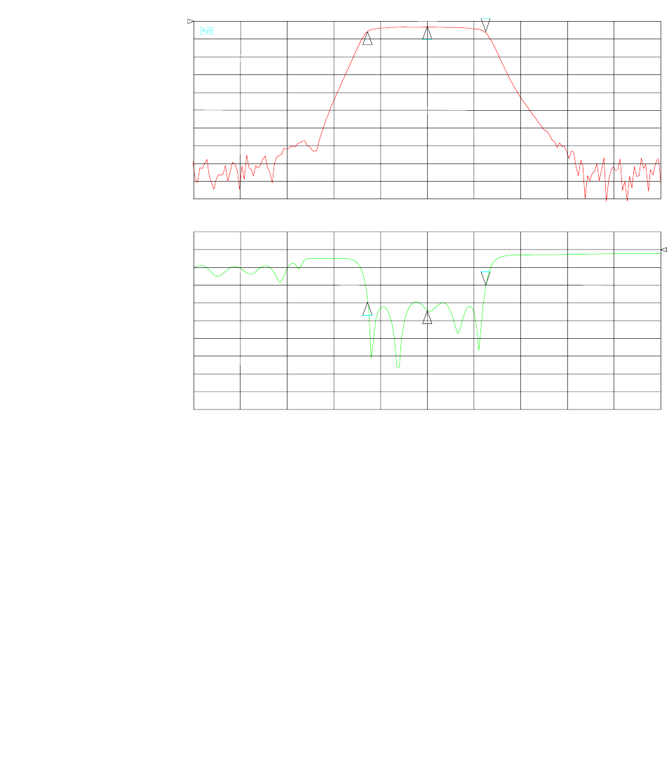
120 Appendix A Transmit or Receive RF Filter Responses
•
•
•
•
•
•
Figure A-9 Filter with center frequency of 5.803 GHz
CH1 B/R log MAG 10 dB/ REF 0 dB
CH2 S 11 log MAG REF 0 dB5 dB/
CENTER 5 803.000 000 MHz
SPAN 150.000 000 MHz
12
33_ -5.8215 dB
5 821.805 002 MHz
1_ -5.8229 dB
5.783 GHz
2_ -2.866 dB
5.803 GHz
12
3
3_:-9.9514 dB
5 821.805 002 MHz
1_:-14.808 dB
5.783 GHz
2_:-17.158 dB
5.803 GHz
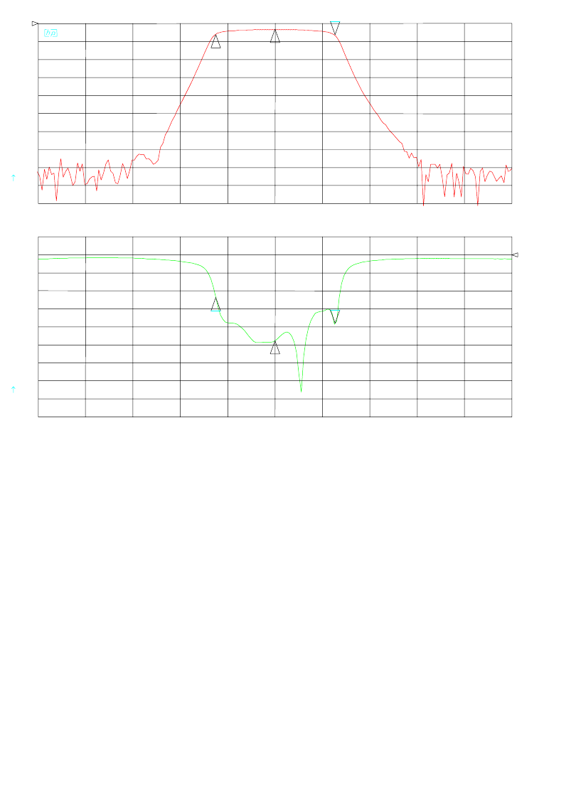
Aurora 5800
121
•
•
•
•
•
•
Figure A-10 Filter with center frequency of 5.834 GHz
CH1 B/R log MAG 10 dB/ REF 0 dB
CH2 S 11 log MAG REF 0 dB5 dB/
CENTER 5 834.000 000 MHz
SPAN 150.000 000 MHz
12
33_ -6.001 dB
5 853.030 120 MHz
1_ -6.0013 dB
5.815 GHz
2_ -3.07 dB
5.834 GHz
1
2
3
3_:-18.937 dB
5 853.030 120 MHz
1_:-11.868 dB
5.815 GHz
2_:-23.856 dB
5.834 GHz

122 Appendix A Transmit or Receive RF Filter Responses
•
•
•
•
•
•
This page intentionally blank.
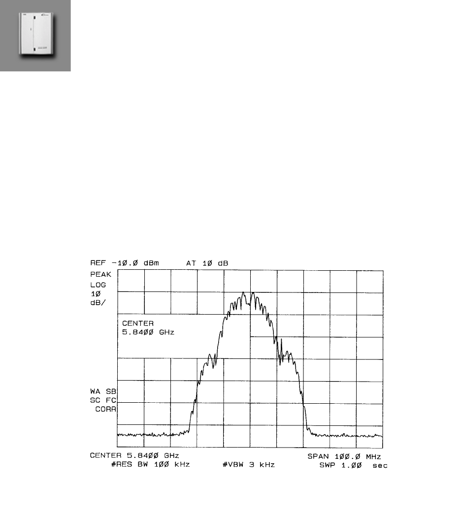
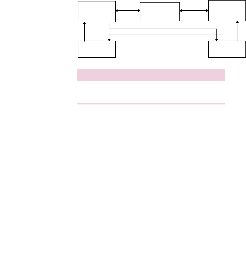
124 Appendix B Typical Radio Performance Results for T1
•
•
•
•
•
•
Receiver Tests
Test Setup
Figure B-2 Receiver test setup
Direction Transmit Receive
A Radio 1 at 5775 MHz Radio 2 at 5775 MHz
B Radio 2 at 5840 MHz Radio 1 at 5840 MHz
40 to 130 dB
Radio 1 Variable
Attenuator Radio 2
BERT BERT

Aurora 5800
125
•
•
•
•
•
•
Receiver Sensitivity
Code used: 2CF8
Requirement: Input threshold at BER 10
-6
≤ −87
dBm
Results: Both directions use same spread sequence.
Code Direction Input Threshold at
BER 10
-6
(dBm)
3F0C A
−
92
B
−
91
2CF8 A
−
91
B
−
90
1F35 A
−
90
B
−
89

126 Appendix B Typical Radio Performance Results for T1
•
•
•
•
•
•
Dispersive Fade Margin
Test Conditions
Direction A code: 1F35
Direction B code: 1F35
Fade simulator is inserted in the 140-MHz IF path.
RCV input level is at nominal - 40 dBm.
Direction A
See Table B-1 and Table B-2 for the results of this test for Direction A.
Table B-1 Direction A, minimal phase
Notch
Frequency
(MHz)
Notch Depth
(dB)
at BER 1E-6
Notch Depth
(dB)
at BER 1E-3
Notch Depth
(dB)
at Sync Loss
Notch Depth
(dB)
at Re-acquisition
134 40 at 134.8 MHz 40 at 136.3 MHz
136 19.0 24.5
138 20.4 24.5 40 at 139.2 MHz 40
140 32.0 33.5 39.4 39.0
142 24.4 27.5 40 at 140.5 MHz 40
144 27.8 40 at 143.5 MHz
145 40 at 144.4 MHz
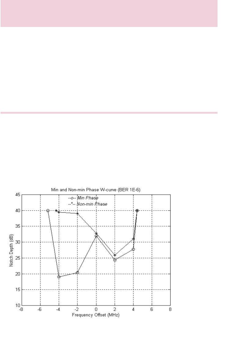
Aurora 5800
127
•
•
•
•
•
•
Table B-2 Direction A, non-minimal phase
DFM = 56.17 dB for BER = 1E-6
DFM = 64.70 dB for BER = 1E-3
See Figure B-3 for the W curve at BER = 1E-6, and Figure B-4 for the
W curve at BER = 1E-3.
Figure B-3 W Curve at BER
=
1E-6, Direction A
Notch
Frequency
(MHz)
Notch Depth
(dB)
at BER 1E-6
Notch Depth
(dB)
at BER 1E-3
Notch Depth
(dB)
at Sync Loss
Notch Depth
(dB)
at Re-acquisition
134 40 at 135.7 MHz
136 39.5 > 40
138 39.0 > 40 > 40.0 > 40.0
140 32.8 > 40 > 40.0 > 40.0
142 25.9 > 40 > 40.0 > 40.0
144 31.0 40 at 143.3 MHz
146 40 at 144.4 MHz
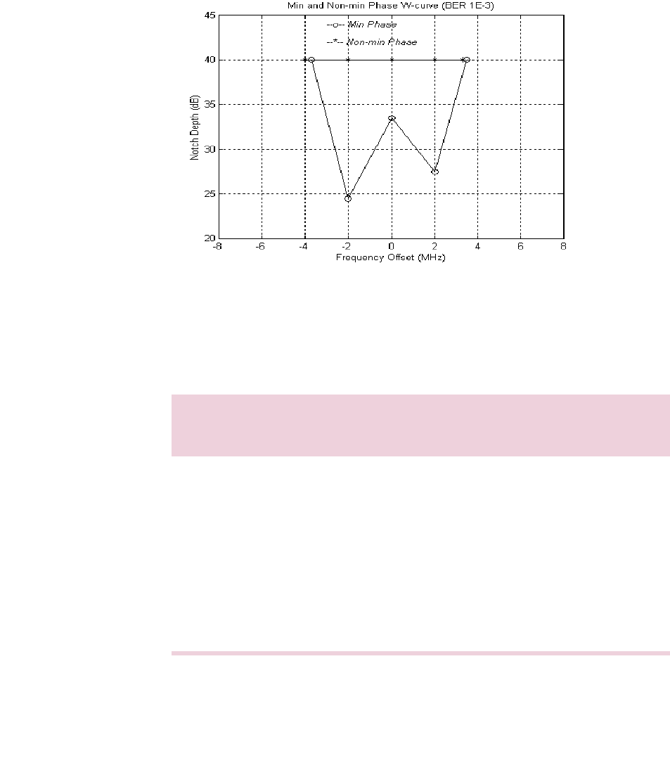
128 Appendix B Typical Radio Performance Results for T1
•
•
•
•
•
•
Figure B-4 W Curve at BER = 1E-3, Direction A
Direction B
See Table B-3 and Table B-4 for the results of this test for Direction B.
Table B-3 Direction B, minimal phase
Notch
Frequency
(MHz)
Notch Depth
(dB)
at BER 1E-6
Notch Depth
(dB)
at BER 1E-3
Notch Depth
(dB)
at Sync Loss
Notch Depth
(dB)
at Re-acquisition
134 40 at 134.8 MHz 40 at 135.8 MHz
136 21.0 28.0
138 27.5 29.5 40 at 138.5 MHz 40.0
140 27.4 32.0 37.0 34.0
142 22.0 28.2 33.0 30.0
144 27.0 > 40 > 40
144.3 40.0
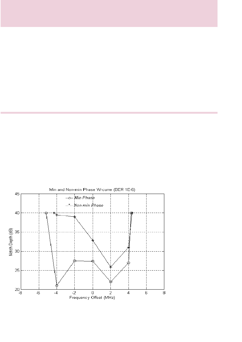
Aurora 5800
129
•
•
•
•
•
•
Table B-4 Direction B, non-minimal phase
DFM = 57.74 dB for BER = 1E-6
DFM = 68.86 dB for BER = 1E-3
See Figure B-5 for the W curve at BER = 1E-6 and Figure B-6 for the
W curve at BER = 1E-3.
Figure B-5 W Curve at BER = 1E-6, Direction B
Notch
Frequency
(MHz)
Notch Depth
(dB)
at BER 1E-6
Notch Depth
(dB)
at BER 1E-3
Notch Depth
(dB)
at Sync Loss
Notch Depth
(dB)
at Re-acquisition
135.7 40.0
136 39.5
138 39.0 > 40.0 > 40.0 > 40.0
140 32.8 > 40.0 > 40.0 > 40.0
142 25.9 28.5 34.0 31.0
144 31.0 40 at 143.3 MHz > 40 > 40
144.4 40.0
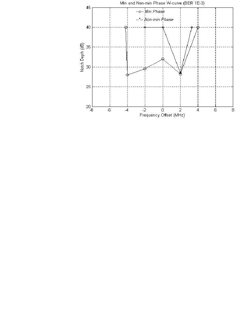
130 Appendix B Typical Radio Performance Results for T1
•
•
•
•
•
•
Figure B-6 W Curve at BER = 1E-3, Direction B

Aurora 5800
131
•
•
•
•
•
•
Dynamic Fading
Sweep Notch Depth Range
See Table B-5 for sweep notch depth range at certain notch frequencies for
BER < 10
-6
region; elapse time = 0.1 sec.
Table B-5 Sweep notch depth range
Sweep Notch Frequency
Table B-6 Checking for error notch depth region, elapse time: 0.1 sec
(equivalent to sweep speed 600 MHz/sec)
Notch
Frequency
(MHz)
Direction A Notch Depth
(dB) Direction B Notch Depth
(dB)
Minimal
Phase Non-minimal
Phase Minimal
Phase Non-minimal
Phase
135.0 0 to 28 0 to 36 0 to 18 0 to 32
138.0 0 to 17 0 to 35 0 to 30 0 to 40
140.0 0 to 26 0 to 30 0 to 31 0 to 26
142.0 0 to 18 0 to 21 0 to 28 0 to 18
145.0 0 to 39 0 to 40 0 to 40 0 to 40
Notch
Frequency
(MHz)
Direction A Notch Depth
(dB) Direction B Notch Depth
(dB)
Minimal
Phase Non-minimal
Phase Minimal
Phase Non-minimal
Phase
115 to 165 17.5 21.0 19.0 22.0

132 Appendix B Typical Radio Performance Results for T1
•
•
•
•
•
•
Flat Fading
Sweep for ultimate error-free attenuation range (flat fading), elapse time:
0.1 sec.
Note
: Attenuation is inserted in the IF path. RF AGC is disabled. Only the
dynamic performance of the IF AGC is tested.
Direction A: 0 to 55 dB
Direction B: 0 to 55 dB
Interference Performance
The effect of an interfering signal into a digital radio receiver is
characterized by a 1 dB degradation in the BER
=
1
×
10
-6
(static) and
1
×
10
-3
(outage) thresholds. The standard for this characteristic is the
threshold-to-interference (T/I) ratio, as defined in EIA/TIA Document TSB-
10-F. [Ref 5]
The test was performed for sinewave (narrowband) interference and for like
signal (wideband) interference. The method used in this test follows the TIA
Bulletin TSB-10-F Standard T/I measurement recommendation.
The C/I uses nominal receiver input level (
−
40 dBm), and then interference
is injected to get a BER of 10
-6
. C/I is the ratio of the signal to interference
ratio at this point, measured in direction A only.
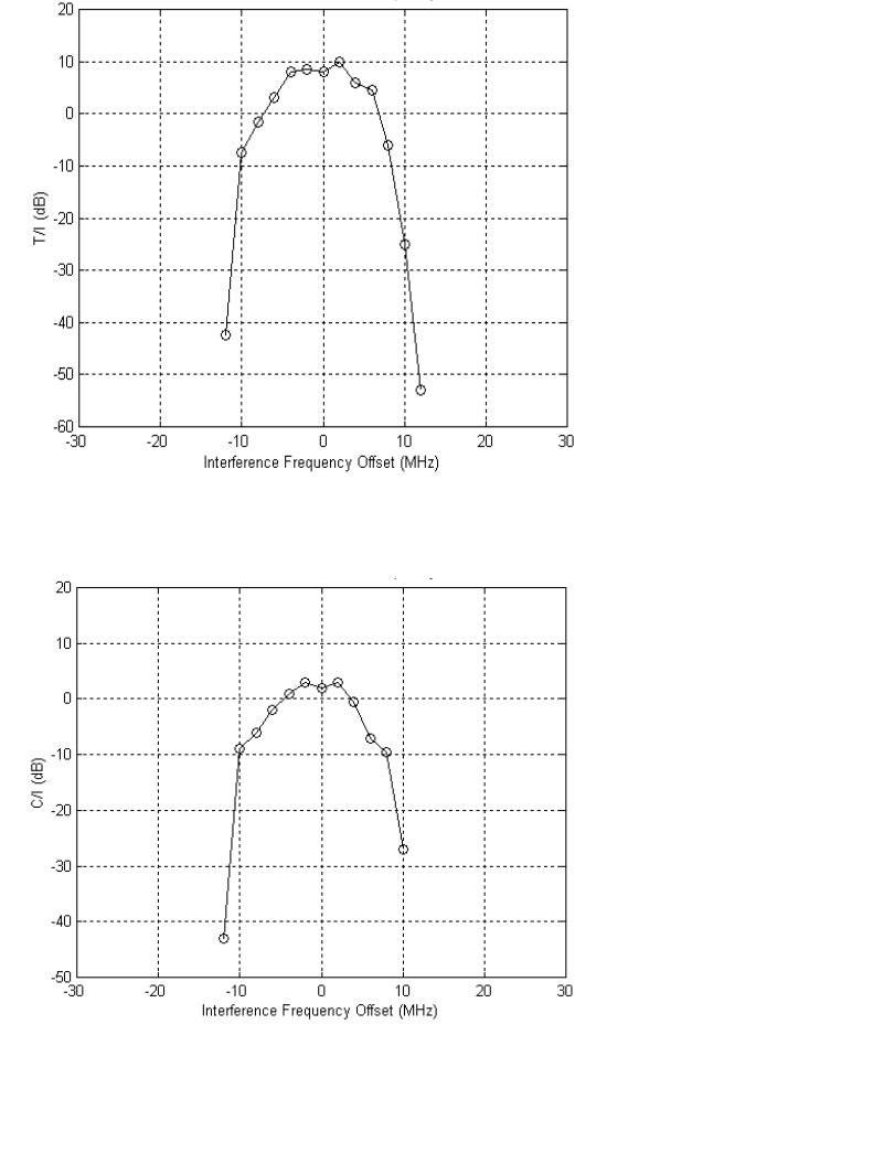
Aurora 5800
133
•
•
•
•
•
•
Narrowband Interference
Figure B-7 T/I versus narrowband interference frequency offset
Figure B-8 C/I versus narrowband interference frequency offset
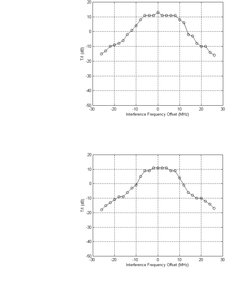
134 Appendix B Typical Radio Performance Results for T1
•
•
•
•
•
•
Wideband Interference
Figure B-9 T/I versus wideband interference frequency offset
(Directions A and B, same code, 1F35)
Figure B-10 T/I versus wideband interference frequency offset (Direction
A: 1F35, Direction B: 3F0C)
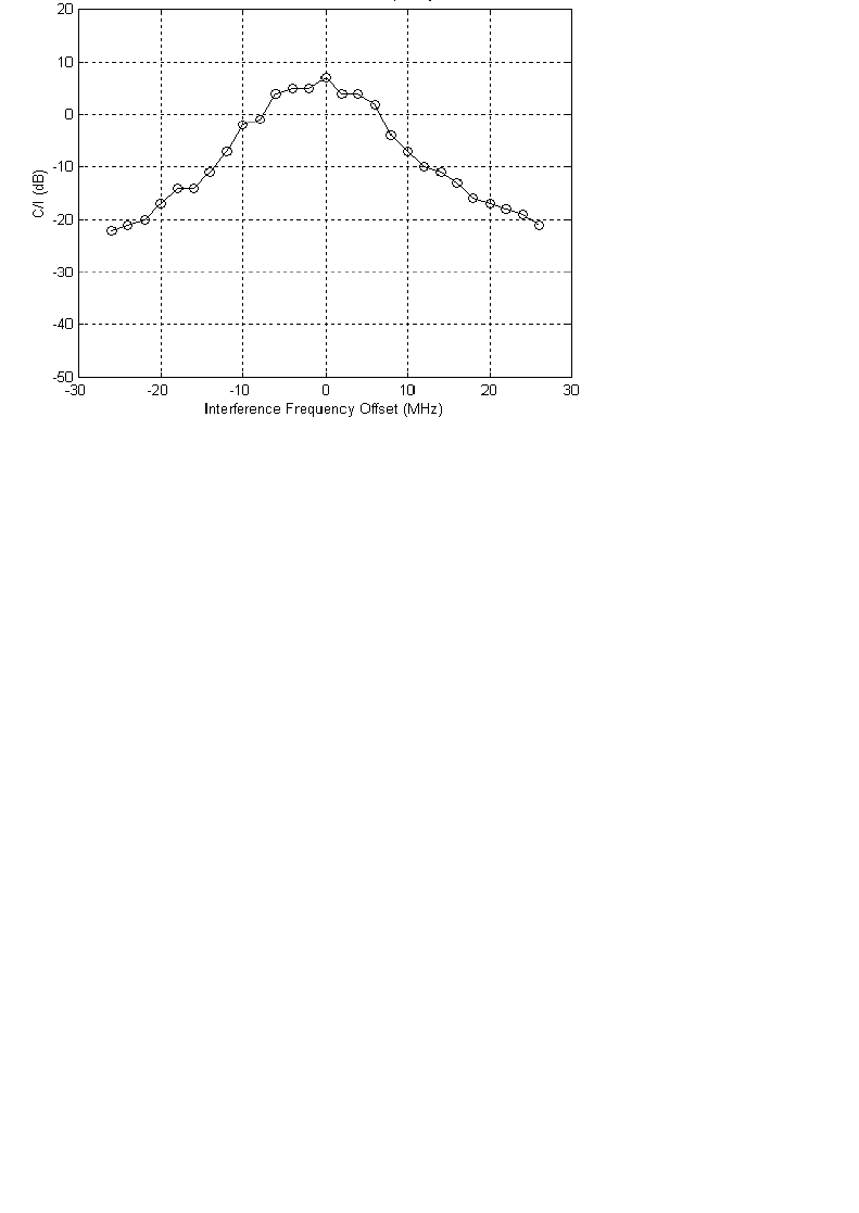
Aurora 5800
135
•
•
•
•
•
•
Figure B-11 C/I versus wideband interference frequency offset
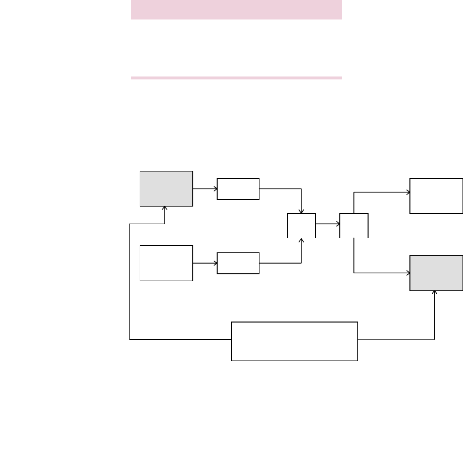
136 Appendix B Typical Radio Performance Results for T1
•
•
•
•
•
•
FCC Part 15, Compliance Processing Gain
Performance Test
Test method recommended by FCC 97-114 is the CW Jamming
Margin Method.
Test Setup
Test setup is shown in Figure B-12.
Figure B-12 Processing gain test setup
Characteristic Value
Data rate T1 (1.544 Mb/s)
Chip rate 11 chips/bit
Designed processing gain 10.4 dB
HP37701A
Communications
Analyzer
Transmitter Variable
Attenuator
Variable
Attenuator
Comb/
Splitter Comb/
Splitter
HP8648C
Signal
Generator
HP435B
Power
Meter
Receiver
Data In
Data Out

Aurora 5800
137
•
•
•
•
•
•
Jamming Margin (J/S Ratio) (for BER 10-5)
The test was performed in Direction B. 50 kHz increments were used in this
test; the worst 20% were discarded. See Table B-7.
After the worst 20% (64 points marked with (x)) were discarded, the lowest
J/S ratio was - 0.5 dB (marked with (**)).
Hence
M
j
=
−
0.5 dB.
The S/N ratio for ideal noncoherent receiver is calculated from
Pe
=
½ e
(-½ (S/N)
o
)
,
where
Pe =
10
-5
.
Hence
(S/N)
o
= 13.3 dB.
The processing gain can be calculated as
G
p
=
(S/N)
o
+
M
j
+
L
sys
where
L
sys
= System Loss.
No more than 2 dB loss is allowed (we assumed 0 dB).
Hence
G
p
= 13.3
−
0.5 + 0.0 = 12.8 dB, better than the designed coding gain
of 10.4 dB and better than the FCC’s minimum requirement of 10 dB.

138 Appendix B Typical Radio Performance Results for T1
•
•
•
•
•
•
Table B-7 Jamming margin (J/S ratio) (for BER 10
-5
) for T1
Freq. Offset
(MHz) J/S
(dB) Freq. Offset
(MHz) J/S
(dB) Freq. Offset
(MHz) J/S
(dB) Freq. Offset
(MHz) J/S
(dB)
−
8.00 5.2
−
6.00 0.8
−
4.00 2.5
−
2.00 (x)
−
0.5
.05 5.3 .05
−
0.1 .05 2.0 .05 (x)
−
0.8
.10 5.6 .10 (x)
−
1.0 .10 1.5 .10 (x)
−
1.1
.15 6.1 .15 (x)
−
1.7 .15 1.4 .15 (x)
−
1.3
.20 6.0 .20 (x)
−
1.8 .20 1.6 .20 (x)
−
1.4
.25 6.2 .25 (x)
−
2.0 .25 1.3 .25 (x)
−
1.5
.30 6.5 .30 (x)
−
2.0 .30 1.3 .30 (x)
−
1.9
.35 6.5 .35 (x)
−
1.7 .35 1.8 .35 (x)
−
1.3
.40 6.8 .40 (x)
−
0.8 .40 1.6 .40 (x)
−
1.3
.45 7.2 .45
−
0.2 .45 1.2 .45 (x)
−
1.3
.50 7.2 .50 1.2 .50 0.8 .50 (x)
−
0.6
.55 6.7 .55 1.9 .55 0.3 .55
−
0.3
.60 6.2 .60 2.8 .60 0.0 .60 0.1
.65 6.0 .65 3.3 .65
−
0.4 .65 0.1
.70 5.4 .70 3.4 .70
−
0.5 .70
−
0.2
.75 5.4 .75 3.6 .75 (x)
−
0.8 .75
−
0.1
.80 4.6 .80 3.9 .80
−
0.2 .80
−
0.3
.85 4.2 .85 3.8 .85
(**)
−
0.5
.85
−
0.2
.90 3.8 .90 3.6 .90
−
0.5 .90 0.1
.95 3.9 .95 2.9 .95 0.4 .95 0.0
−
7.00 3.8
−
5.00 2.3
−
3.00 0.5
−
1.00 0.6
.05 3.7 .05 1.9 .05 1.0 .05 0.9
.10 3.8 .10 1.2 .10 1.3 .10 1.8
.15 3.7 .15 1.0 .15 1.2 .15 2.1
.20 3.7 .20 0.5 .20 2.0 .20 2.1
.25 3.8 .25 0.8 .25 2.6 .25 2.1
.30 3.3 .30 0.8 .30 3.0 .30 2.4
.35 3.7 .35 0.8 .35 3.9 .35 2.5
.40 3.7 .40 1.5 .40 4.5 .40 2.3
.45 4.2 .45 1.5 .45 4.4 .45 2.2
.50 4.3 .50 1.6 .50 4.2 .50 1.5
.55 3.7 .55 2.1 .55 4.0 .55 1.0
.60 3.1 .60 2.1 .60 3.5 .60
−
0.1
.65 3.0 .65 2.8 .65 3.2 .65 (x)
−
1.7
.70 2.9 .70 2.8 .70 2.9 .70 (x)
−
3.0
.75 2.8 .75 2.9 .75 2.1 .75 (x)
−
4.0
.80 3.1 .80 3.4 .80 1.9 .80 (x)
−
4.6
.85 3.5 .85 3.9 .85 0.8 .85 (x)
−
4.8
.90 3.0 .90 3.9 .90 0.8 .90 (x)
−
5.2
.95 3.4 .95 3.3 .95 0.3 .95 (x)
−
5.8

Aurora 5800
139
•
•
•
•
•
•
0.00 (x)
−
4.3 +2.00 (x)
−
2.1 +4.00 3.9 +6.00
−
0.2
.05 (x)
−
4.3 .05 (x)
−
2.1 .05 4.4 .05 2.0
.10 (x)
−
4.9 .10 (x)
−
1.8 .10 4.1 .10 2.2
.15 (x)
−
4.7 .15 (x)
−
1.1 .15 4.0 .15 2.8
.20 (x)
−
3.8 .20 0.0 .20 3.5 .20 3.6
.25 (x)
−
3.5 .25 0.5 .25 3.5 .25 4.5
.30 (x)
−
2.2 .30 1.1 .30 2.8 .30 5.1
.35 (x)
−
1.4 .35 2.0 .35 2.3 .35 6.0
.40 (x)
−
0.5 .40 2.6 .40 1.7 .40 6.1
.45 0.1 .45 3.3 .45 1.2 .45 6.4
.50 0.3 .50 3.5 .50 1.0 .50 6.0
.55 0.3 .55 3.3 .55 0.7 .55 5.1
.60 0.7 .60 2.8 .60 0.7 .60 4.4
.65 0.8 .65 2.4 .65 1.1 .65 4.0
.70 0.8 .70 1.9 .70 1.1 .70 3.4
.75 0.8 .75 1.3 .75 1.6 .75 3.1
.80 1.2 .80 0.6 .80 1.6 .80 3.1
.85 1.2 .85
−
0.3 .85 2.2 .85 3.4
.90 1.3 .90 (x)
−
0.8 .90 2.4 .90 3.4
.95 0.8 .95 (x)
−
1.1 .95 2.8 .95 4.0
+1.00 0.4 +3.00 (x)
−
1.4 +5.00 3.5 +7.00 4.1
.05
−
0.2 .05 (x)
−
0.5 .05 3.4 .05 4.2
.10 (x)
−
0.5 .10
−
0.1 .10 3.4 .10 5.2
.15 (x)
−
1.5 .15
−
0.1 .15 2.9 .15 5.9
.20 (x)
−
1.7 .20 0.0 .20 2.3 .20 6.4
.25 (x)
−
1.8 .25 0.0 .25 1.9 .25 7.2
.30 (x)
−
2.6 .30 0.8 .30 2.2 .30 7.6
.35 (x)
−
2.2 .35 1.0 .35 2.2 .35 7.9
.40 (x)
−
2.5 .40 1.1 .40 2.1 .40 7.9
.45 (x)
−
2.1 .45 1.2 .45 2.3 .45 7.9
.50 (x)
−
2.4 .50 0.8 .50 1.7 .50 7.7
.55 (x)
−
2.3 .55 0.7 .55 1.3 .55 7.0
.60 (x)
−
2.4 .60 0.8 .60 0.8 .60 6.2
.65 (x)
−
3.0 .65 0.9 .65 0.8 .65 5.5
.70 (x)
−
2.5 .70 0.7 .70
−
0.2 .70 5.4
.75 (x)
−
1.7 .75 1.4 .75 (x)
−
0.5 .75 5.7
.80 (x)
−
1.9 .80 1.2 .80 (x)
−
0.5 .80 5.9
.85 (x)
−
1.9 .85 1.3 .85
−
0.3 .85 6.4
.90 (x)
−
1.8 .90 2.2 .90
−
0.3 .90 6.3
.95 (x)
−
2.1 .95 2.8 .95 (x)
−
0.7 .95 6.5
+8.00 6.7
Freq. Offset
(MHz) J/S
(dB) Freq. Offset
(MHz) J/S
(dB) Freq. Offset
(MHz) J/S
(dB) Freq. Offset
(MHz) J/S
(dB)
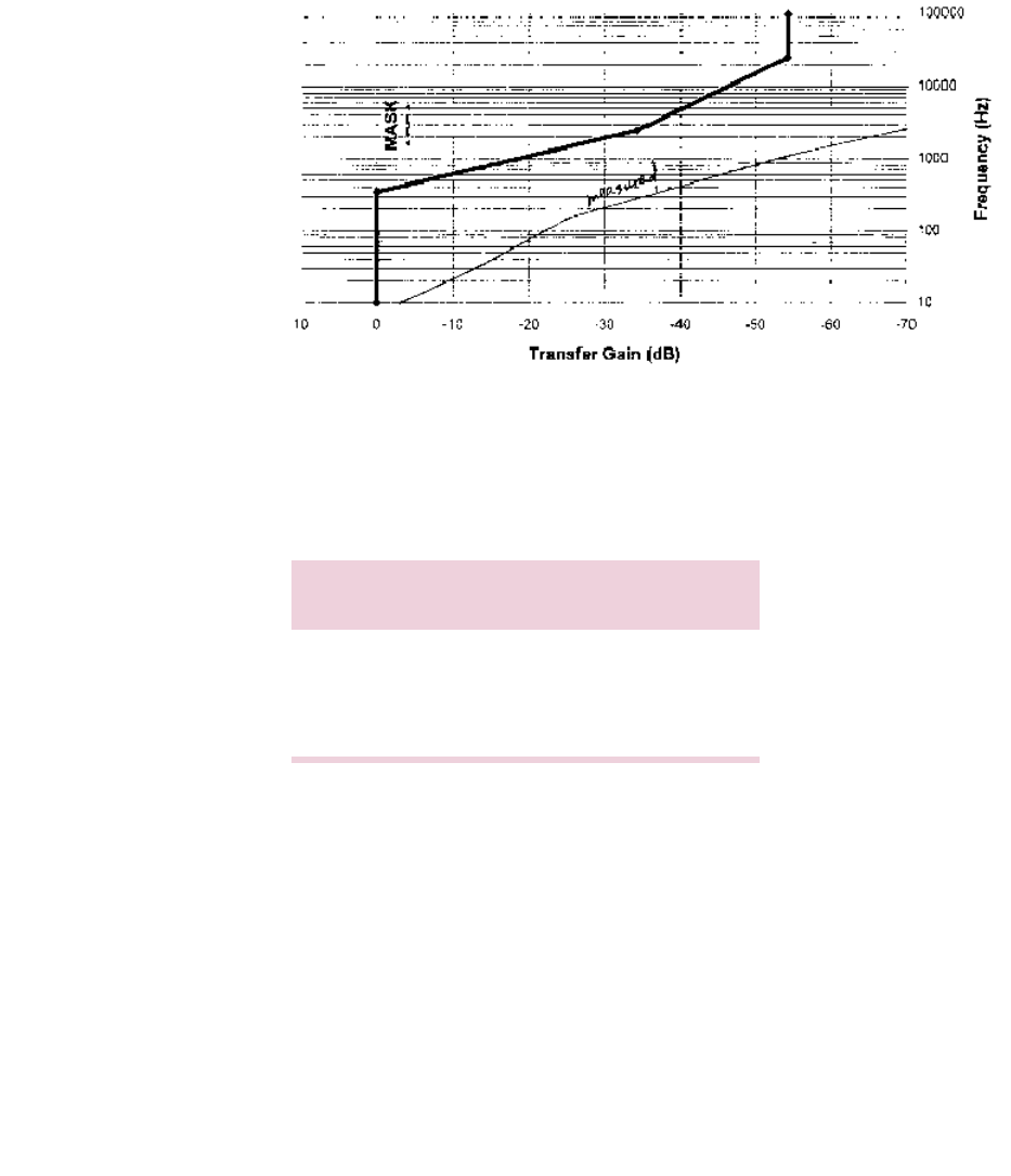
140 Appendix B Typical Radio Performance Results for T1
•
•
•
•
•
•
Jitter Transfer Function
Figure 0-1 Jitter transfer (DS1)
Environmental Performance
Temperature Performance
Direction B, Code: 2CF8
Long-Term Error Performance
Receiver input level is set at the nominal
−
40 dBm at room temperature.
Both transmitter and receiver achieved error-free performance over
temperature cycling for 0
o
C to +50
o
C for continuous 8-hour testing.
Power Consumption Measurement
Input: 110 VAC
Power consumed: 21 watts
Temperature
(°C) Tx Power
(dBm) Rx Threshold
(dBm)
019.2
−
91
25 19.0
−
90
50 18.7
−
88.5
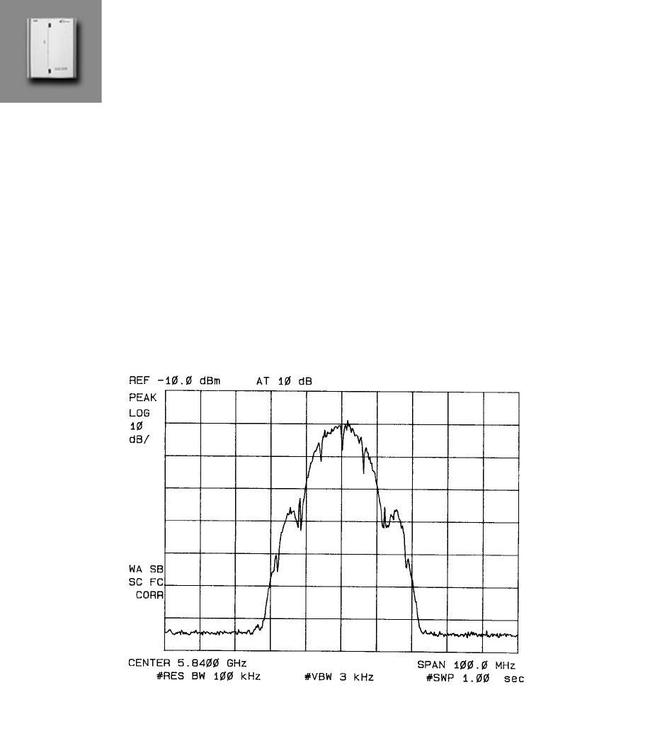
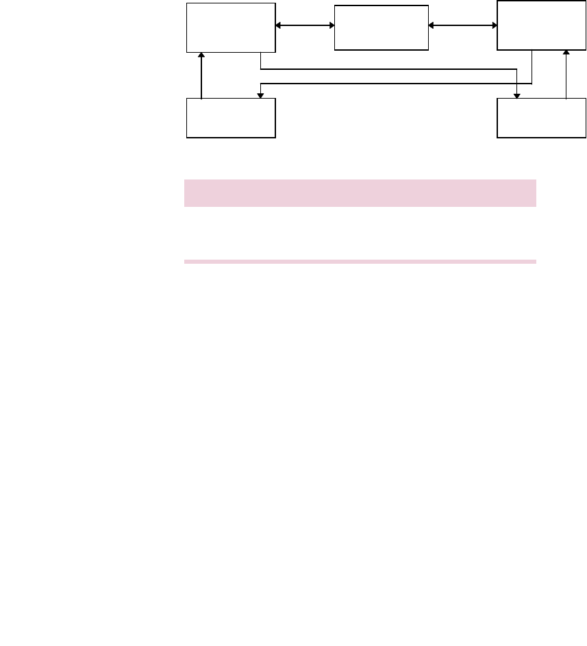
142 Appendix C Typical Radio Performance Results for E1
•
•
•
•
•
•
Receiver Tests
Test Setup
Figure C-2 Receiver test setup
Direction Transmit Receive
A Radio 1 at 5775 MHz Radio 2 at 5775 MHz
B Radio 2 at 5840 MHz Radio 1 at 5840 MHz
40 to 130 dB
Radio 1 Variable
Attenuator Radio 2
BERT BERT

Aurora 5800
143
•
•
•
•
•
•
Receiver Sensitivity
Code used: 05B8
Requirement: Input threshold at BER 10
-6
≤ −87
dBm
Results: Both directions use same spread sequence.
Table C-1 Receiver sensitivity
Dispersive Fade Margin
Test Conditions
Direction A code: 05B8
Direction B code: 05B8
Fade simulator is inserted in the 140-MHz IF path.
RCV input level is at nominal
−
40 dBm.
Direction A
See Table C-2 and Table C-3 for the results of this test for Direction A.
Direction Rx Input
(dBm) At
A
−
90 BER = 1E-6
−
94 BER = 1E-3
−
96 Sync loss
−
95 Re-acquisition
B
−
89 BER = 1E-6
−
93 BER = 1E-3
−
96 Sync loss
−
95 Re-acquisition

144 Appendix C Typical Radio Performance Results for E1
•
•
•
•
•
•
Table C-2 Direction A, minimal phase
Table C-3
Direction A,
non-minimal phase
DFM = 62.17 dB for BER = 1E-6
DFM = 70.26 dB for BER = 1E-3
See Figure C-3 for the W curve at BER = 1E-6, and Figure C-4 for the
W curve at BER = 1E-3.
Notch
Frequency
(MHz)
Notch Depth
(dB)
at BER 1E-6
Notch Depth
(dB)
at BER 1E-3
Notch Depth
(dB)
at Sync Loss
Notch Depth
(dB)
at Re-acquisition
40 at 135.7 MHz
136 24.0 40 at 135.1 MHz
138 29.3 33.1 > 40 > 40
140 33.4 36.4 > 40 > 40
142 27.1 32.0 > 40 > 40
144 30.0 40 at 142.7 MHz
40 at 144.4 MHz
Notch
Frequency
(MHz)
Notch Depth
(dB)
at BER 1E-6
Notch Depth
(dB)
at BER 1E-3
Notch Depth
(dB)
at Sync Loss
Notch Depth
(dB)
at Re-acquisition
40 at 135.9 MHz
136 39.0
138 34.7 > 40 > 40.0 > 40.0
140 > 40 > 40 > 40.0 > 40.0
142 28.0 34 > 40.0 > 40.0
144 40 40 at 142.6 MHz
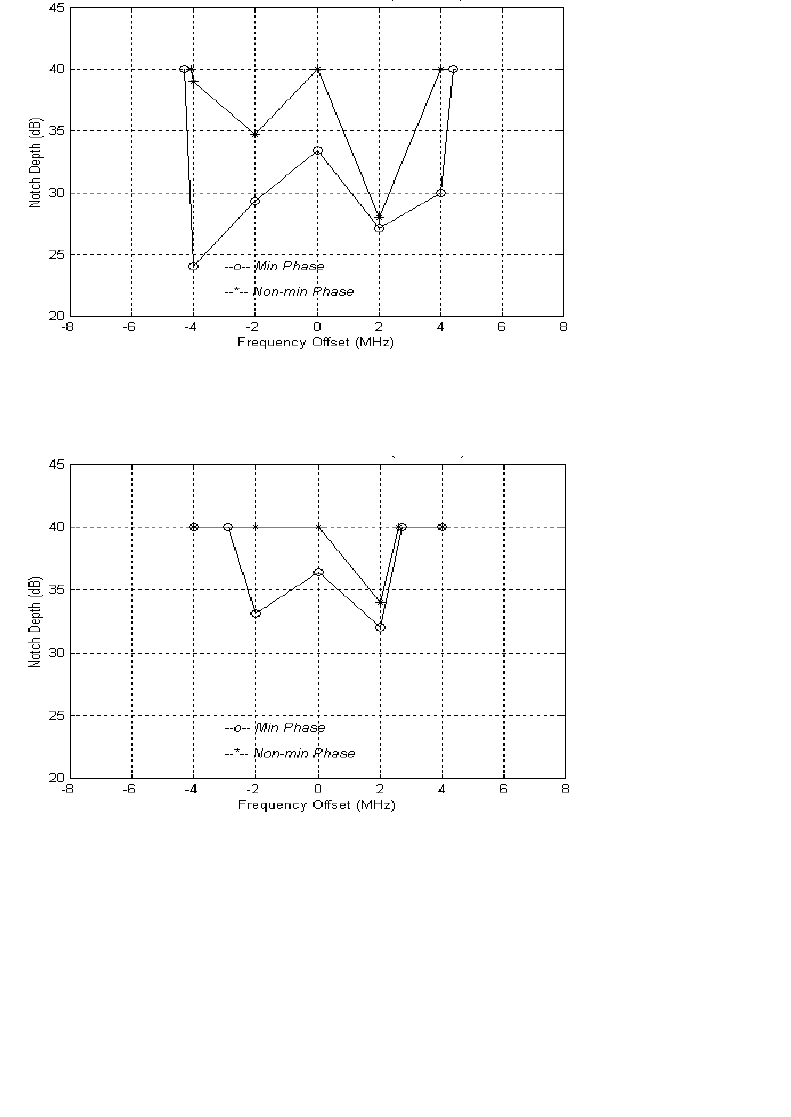
Aurora 5800
145
•
•
•
•
•
•
Figure C-3 W Curve at BER
=
1E-6, Direction A
Figure C-4 W Curve at BER = 1E-3, Direction A

146 Appendix C Typical Radio Performance Results for E1
•
•
•
•
•
•
Direction B
See Table C-4 and Table C-5 for the results of this test for Direction B.
Table C-4 Direction B, minimal phase
Table C-5 Direction B, non-minimal phase
DFM = 66.91 dB for BER = 1E-6
DFM = 71.05 dB for BER = 1E-3
See Figure C-5 for the W curve at BER = 1E-6 and Figure C-6 for the
W curve at BER = 1E-3.
Notch
Frequency
(MHz)
Notch Depth
(dB)
at BER 1E-6
Notch Depth
(dB)
at BER 1E-3
Notch Depth
(dB)
at Sync Loss
Notch Depth
(dB)
at Re-acquisition
40 at 135.9 MHz
136 39.0
138 34.7 > 40 > 40.0 > 40.0
140 > 40 > 40 > 40.0 > 40.0
142 28.0 34 > 40.0 > 40.0
144 40 40 at 142.6 MHz
Notch
Frequency
(MHz)
Notch Depth
(dB)
at BER 1E-6
Notch Depth
(dB)
at BER 1E-3
Notch Depth
(dB)
at Sync Loss
Notch Depth
(dB)
at Re-acquisition
136 40 at 136.2 MHz
138 39.1 > 40 > 40 > 40
140 > 40 > 40 > 40 > 40
142 33.3 > 40 > 40 > 40
144 40 at 143.6 MHz
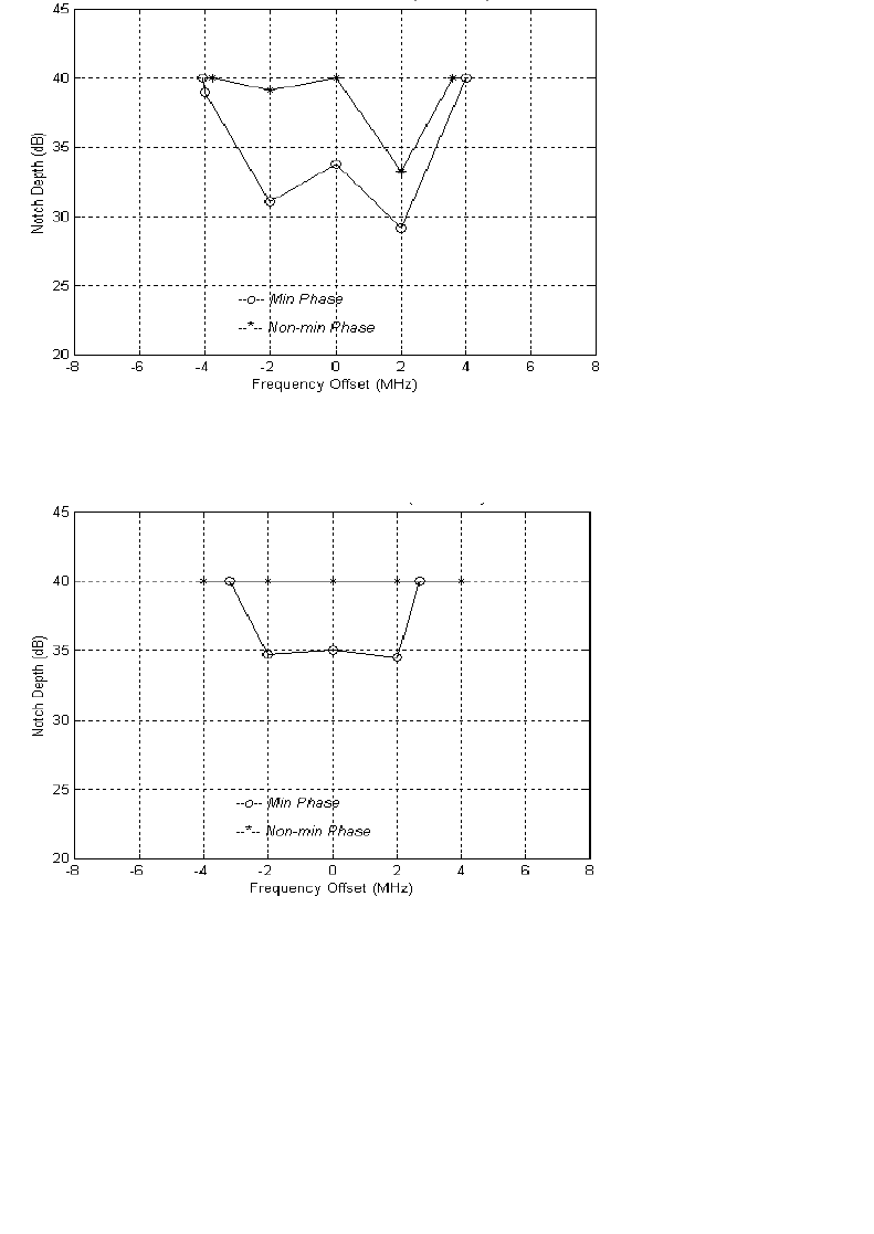
Aurora 5800
147
•
•
•
•
•
•
Figure C-5 W Curve at BER = 1E-6, Direction B
Figure C-6 W Curve at BER = 1E-3, Direction B

148 Appendix C Typical Radio Performance Results for E1
•
•
•
•
•
•
Dynamic Fading
Sweep Notch Depth Range
Table C-6 Sweep notch depth range for ultimate error-free region
(elapse time: 0.1 sec)
Sweep Notch Frequency
Table C-7 Checking for error notch depth region, elapse time: 0.1 sec
(equivalent to sweep speed 600 MHz/sec)
Flat Fading
Sweep for ultimate error-free attenuation range (flat fading), elapse time:
0.1 sec.
Note
: Attenuation is inserted in the IF path. RF AGC is disabled. Only the
dynamic performance of the IF AGC is tested.
Direction A: 0 to 65 dB
Direction B: 0 to 65 dB
Notch
Frequency
(MHz)
Direction A Notch Depth
(dB) Direction B Notch Depth
(dB)
Minimal
Phase Non-minimal
Phase Minimal
Phase Non-minimal
Phase
135.0 0 to 40 0 to 40 0 to 40 0 to 40
140.0 0 to 33 0 to 40 0 to 32 0 to 40
145.0 0 to 40 0 to 40 0 to 40 0 to 40
Notch
Frequency
(MHz)
Direction A Notch Depth
(dB) Direction B Notch Depth
(dB)
Minimal
Phase Non-minimal
Phase Minimal
Phase Non-minimal
Phase
115 to 165 23.0 27.0 28.0 32.0
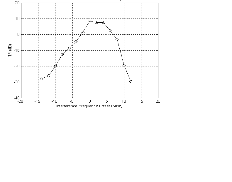
Aurora 5800
149
•
•
•
•
•
•
Interference Performance
The effect of an interfering signal into a digital radio receiver is
characterized by a 1 dB degradation in the BER
=
1
×
10
-6
(static) and
1
×
10
-3
(outage) thresholds. The standard for this characteristic is the
threshold-to-interference (T/I) ratio, as defined in EIA/TIA Document
TSB-10-F. [5]
The test was performed for sinewave (narrowband) interference and for like
signal (wideband) interference. The method used in this test follows the TIA
Bulletin TSB-10-F Standard T/I measurement recommendation.
The C/I uses nominal receiver input level (
−
40 dBm), and then interference
is injected to get a BER of 10
-6
. C/I is the ratio of the signal to interference
ratio at this point, measured in direction A only.
Narrowband Interference
Figure C-7 T/I versus narrowband interference frequency offset
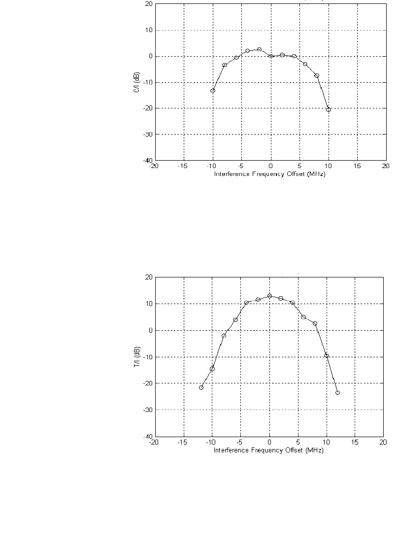
150 Appendix C Typical Radio Performance Results for E1
•
•
•
•
•
•
Figure C-8 C/I versus narrowband interference frequency offset
Wideband Interference
Figure C-9 T/I versus wideband interference frequency offset
(Directions A and B, same code, 05B8)
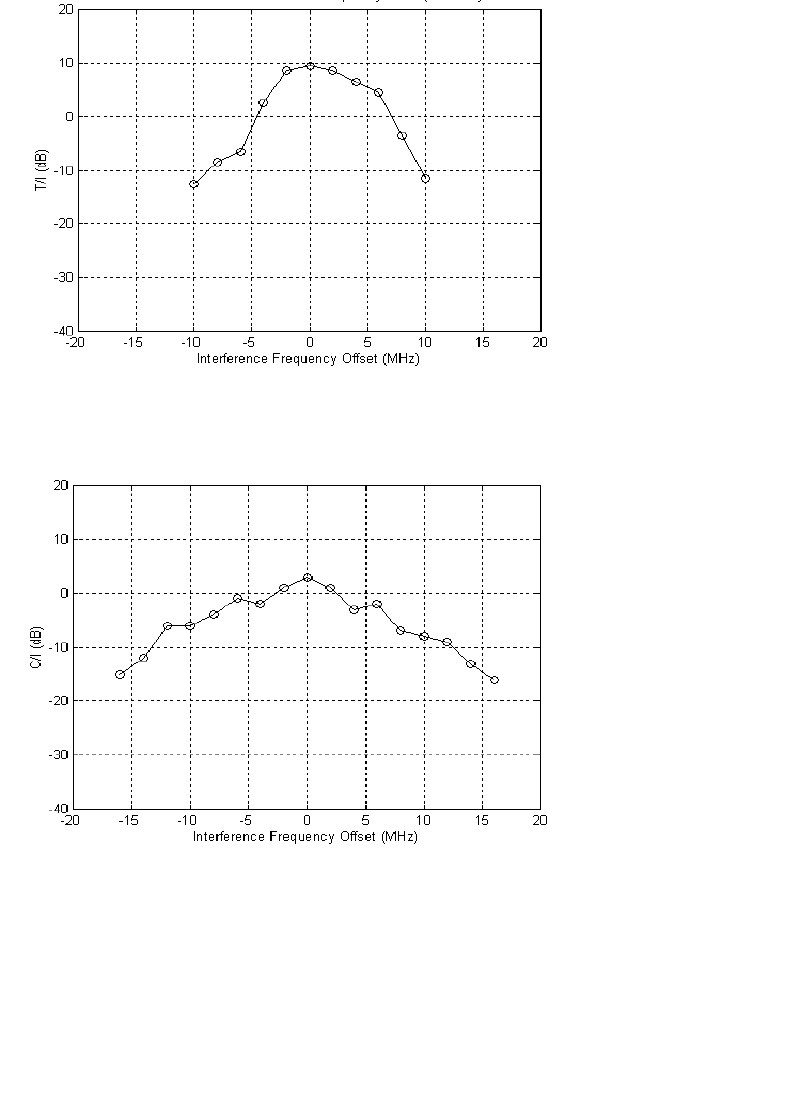
Aurora 5800
151
•
•
•
•
•
•
Figure C-10 T/I versus wideband interference frequency offset (Direction
A: 05B8, Direction B: 0247)
Figure C-11 C/I versus wideband interference frequency offset

152 Appendix C Typical Radio Performance Results for E1
•
•
•
•
•
•
Jitter Performance
Input Jitter Tolerance
HDB3 input ports were tested according to ITU-T Rec. G.823,
Table 2 (2
15
−
1 pseudorandom test signal used).
Table C-8 Test results, input jitter tolerance
The input jitter tolerance complies with Figure 3/G.823 and Table 2/G.823
requirements.
Output Jitter
The output jitter complies with Figure 4/G.823 and Table 3/G.921 (same
pseudorandom test signal used as in preceding test). The output jitter in the
absence of input jitter frequency in the range f
0
to f
4
, is less than 0.1 UI
p-p
;
Table 3/G.921 allows for 0.2 UI
p-p
.
Jitter Gain
The jitter gain in the frequency range, f
0
to f
4
, is far below (worst case,
−
4 dB) the limit of 3 dB specified in Section 1.3.2.3/G.921.
Test
Frequency Jitter Frequency
(Hz)
Tolerable Input Jitter
(UI
p-p
)G.823 Lower Limit
(UI
p-p
)
f
0
1.2
×
10
-5
> 40 36.9
f
1
20 10 1.5
f
2
2.4 k 10 1.5
f
3
18 k 3.6 0.2
f
4
100 k 0.7 0.2

Aurora 5800
153
•
•
•
•
•
•
Jitter Transfer Characteristic
Table C-9 shows that test results exceeded the standards of Figure 4/G.823
and AT&T 62411.
Table C-9 Test results, jitter transfer characteristic
Environmental Performance
Temperature Performance
Long-Term Error Performance
Receiver input level is set at the nominal
−
40 dBm at room temperature.
Both transmitter and receiver achieved error-free performance over
temperature cycling for 0
o
C to +50
o
C for continuous 8-hour testing.
Test
Frequency Jitter Frequency
(Hz) Jitter Attenuation
(dB)
AT&T 62411
Upper Limit
(dB)
f
0
1.2
×
10
-5
4.0 0
f
5
20 28.0 0
f
6
2 k 45.0 40
> 2 k > 45.0 40
Temperature
(°C) Tx Power
(dBm) Rx Threshold
(dBm)
019.2
−
91
25 19.0
−
89
50 18.7
−
88.5

154 Appendix C Typical Radio Performance Results for E1
•
•
•
•
•
•
Power Consumption Measurement
Input: 110 VAC
Power consumed: 21 watts

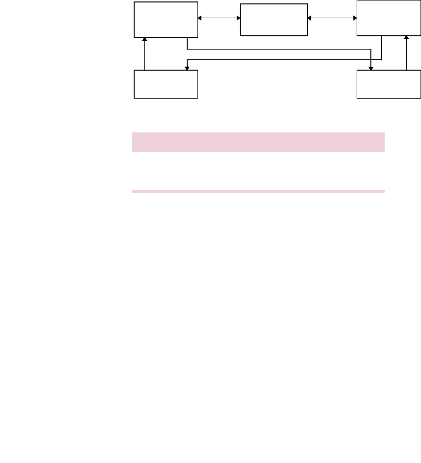
156 Appendix D Typical Radio Performance Results for 2T1
•
•
•
•
•
•
Receiver Tests
Test Setup
Figure D-2 Receiver test setup
Direction Transmit Receive
A Radio 1 at 5741 MHz Radio 2 at 5741 MHz
B Radio 2 at 5803 MHz Radio 1 at 5803 MHz
40 to 130 dB
Radio 1 Variable
Attenuator Radio 2
BERT BERT

Aurora 5800
157
•
•
•
•
•
•
Receiver Sensitivity
Code used: 05B8
Requirement: Input threshold at BER 10
-6
≤ −85
dBm
Results: Both directions use same spread sequence.
Table D-1 Receiver sensitivity
Dispersive Fade Margin
Test Conditions
Direction A code: 05B8
Direction B code: 05B8
Fade simulator is inserted in the 140-MHz IF path.
RCV input level is at nominal
−
40 dBm.
Direction Rx Input
(dBm) At
A
−
90 BER = 1E-6
−
95 Sync loss
−
94 Re-acquisition
B
−
89 BER = 1E-6
−
94 Sync loss
−
93 Re-acquisition

158 Appendix D Typical Radio Performance Results for 2T1
•
•
•
•
•
•
Direction A
See Table D-2 and Table D-3 for the results of this test for Direction A.
Table D-2 Direction A, minimal phase
Table D-3 Direction A, non-minimal phase
Notch
Frequency
(MHz)
Notch Depth
(dB)
at BER 1E-6
Notch Depth
(dB)
at BER 1E-3
Notch Depth
(dB)
at Sync Loss
Notch Depth
(dB)
at Re-acquisition
134 40.0
136 28.0 > 40 > 40 > 40
138 25.5 > 40 > 40 > 40
140 29.5 > 40 > 40 > 40
142 29.5 > 40 > 40 > 40
144 31.5 > 40 > 40 > 40
146 40 at 144.5 MHz
Notch
Frequency
(MHz)
Notch Depth
(dB)
at BER 1E-6
Notch Depth
(dB)
at BER 1E-3
Notch Depth
(dB)
at Sync Loss
Notch Depth
(dB)
at Re-acquisition
134 > 40
136 > 40 > 40 > 40 > 40
138 > 40 > 40 > 40 > 40
140 > 40 > 40 > 40 > 40
142 34.0 > 40 > 40 > 40
144 30.0 > 40 > 40 > 40
146 40 at 144.8 MHz
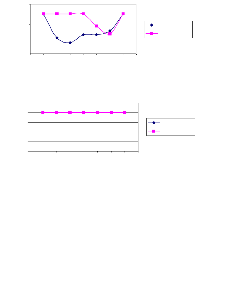
Aurora 5800
159
•
•
•
•
•
•
DFM = 61.68 dB for BER = 1E-6
DFM = 74.54 dB for BER = 1E-3
See Figure D-3 for the W curve at BER = 1E-6, and Figure D-4 for the
W curve at BER = 1E-3.
Figure D-3 W Curve at BER
=
1E-6, Direction A
Figure D-4 W Curve at BER
=
1E-3, Direction A
20
25
30
35
40
45
-8 -6 -4 -2 0 2 4 6 8
Frequency Offset (MHz)
Notch depth (dB)
Min-Phase
Non-min Phase
20
25
30
35
40
45
-8 -6 -4 -2 0 2 4 6 8
Frequency Offset (MHz)
Notch depth (dB)
Min Phase
Non-min Phase

160 Appendix D Typical Radio Performance Results for 2T1
•
•
•
•
•
•
Direction B
See Table D-4 and Table D-5 for the results of this test for Direction B.
Table D-4 Direction B, minimal phase
Table D-5 Direction B, non-minimal phase
Notch
Frequency
(MHz)
Notch Depth
(dB)
at BER 1E-6
Notch Depth
(dB)
at BER 1E-3
Notch Depth
(dB)
at Sync Loss
Notch Depth
(dB)
at Re-acquisition
134 40 at 134.5 MHz
136 28.5 > 40 > 40 > 40
138 40.0 > 40 > 40 > 40
140 31.0 > 40 > 40 > 40
142 31.0 > 40 > 40 > 40
144 34.0 > 40 > 40 > 40
146 40 at 144.6 MHz
Notch
Frequency
(MHz)
Notch Depth
(dB)
at BER 1E-6
Notch Depth
(dB)
at BER 1E-3
Notch Depth
(dB)
at Sync Loss
Notch Depth
(dB)
at Re-acquisition
134 > 40
136 > 40 > 40 > 40 > 40
138 > 40 > 40 > 40 > 40
140 > 40 > 40 > 40 > 40
142 37.0 > 40 > 40 > 40
144 39.0 > 40 > 40 > 40
146 40 at 144.2 MHz
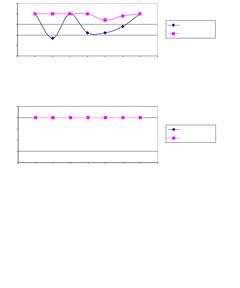
Aurora 5800
161
•
•
•
•
•
•
DFM = 66.27 dB for BER = 1E-6
DFM = 74.54 dB for BER = 1E-3
See Figure D-5 for the W curve at BER = 1E-6 and Figure D-6 for the
W curve at BER = 1E-3.
Figure D-5 W Curve at BER
=
1E-6, Direction B
Figure D-6 W Curve at BER = 1E-3, Direction B
20
25
30
35
40
45
-8 -6 -4 -2 0 2 4 6 8
Frequency Offset (MHz)
Notch depth (dB)
Min Phase
Non-min Phase
20
25
30
35
40
45
-8 -6 -4 -2 0 2 4 6 8
Frequency Offset (MHz)
Notch depth (dB)
Min Phase
Non-min phase

162 Appendix D Typical Radio Performance Results for 2T1
•
•
•
•
•
•
Dynamic Fading
Sweep Notch Depth Range
Table D-6 Sweep notch depth range for ultimate error-free region
(elapse time: 0.1 sec)
Sweep Notch Frequency
Table D-7 Checking for error notch depth region, elapse time: 0.1 sec
(equivalent to sweep speed 600 MHz/sec)
Flat Fading
Sweep for ultimate error-free attenuation range (flat fading), elapse time:
0.1 sec.
Note
: Attenuation is inserted in the IF path. RF AGC is disabled. Only the
dynamic performance of the IF AGC is tested.
Direction A: 0 to 62 dB
Direction B: 0 to 64 dB
Notch
Frequency
(MHz)
Direction A Notch Depth
(dB) Direction B Notch Depth
(dB)
Minimal
Phase Non-minimal
Phase Minimal
Phase Non-minimal
Phase
135.0 28.0 > 40 26.0 > 40
140.0 30.0 > 40 31.0 > 40
145.0 30.0 > 40 > 40 > 40
Notch
Frequency
(MHz)
Direction A Notch Depth
(dB) Direction B Notch Depth
(dB)
Minimal
Phase Non-minimal
Phase Minimal
Phase Non-minimal
Phase
115 to 165 26.0 31.0 24.0 28.0

Aurora 5800
163
•
•
•
•
•
•
Interference Performance
The effect of an interfering signal into a digital radio receiver is
characterized by a 1-dB degradation in the BER
=
1
×
10
-6
(static) and
1
×
10
-3
(outage) thresholds. The standard for this characteristic is the
threshold-to-interference (T/I) ratio, as defined in EIA/TIA Document
TSB-10-F. [5]
The test was performed for sinewave (narrowband) interference and for like
signal (wideband) interference. The method used in this test follows the TIA
Bulletin TSB-10-F Standard T/I measurement recommendation.
The C/I uses nominal receiver input level (
−
40 dBm), and then interference
is injected to get a BER of 10
-6
. C/I is the ratio of the signal to interference
ratio at this point, measured in direction A only.
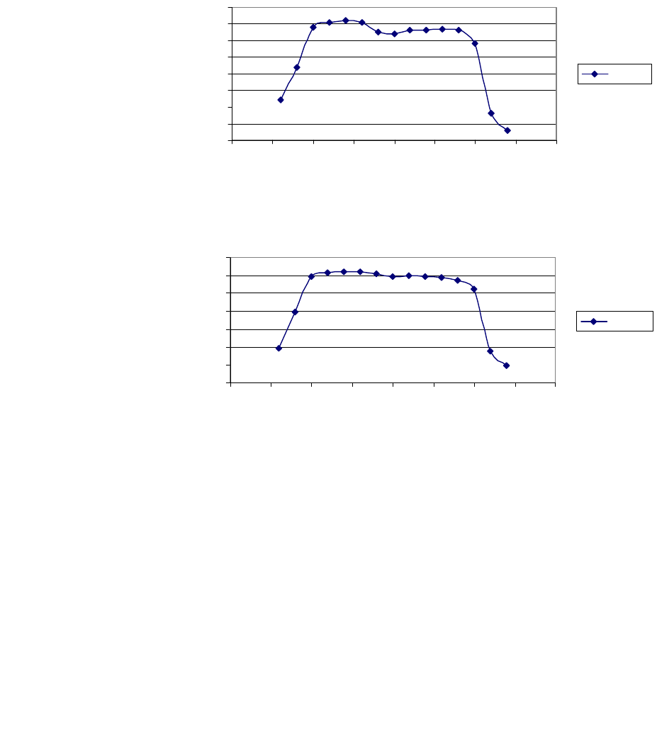
164 Appendix D Typical Radio Performance Results for 2T1
•
•
•
•
•
•
Narrowband Interference
Figure D-7 T/I versus narrowband interference frequency offset
Figure D-8 C/I versus narrowband interference frequency offset
-60
-50
-40
-30
-20
-10
0
10
20
-20 -15 -10 -5 0 5 10 15 20
Interference Frequency Offset
T/I (dB)
T/I (dB)
-60
-50
-40
-30
-20
-10
0
10
-20-15-10-5 0 5 101520
Interference Frequency Offset
C/I (dB)
C/I (dB)
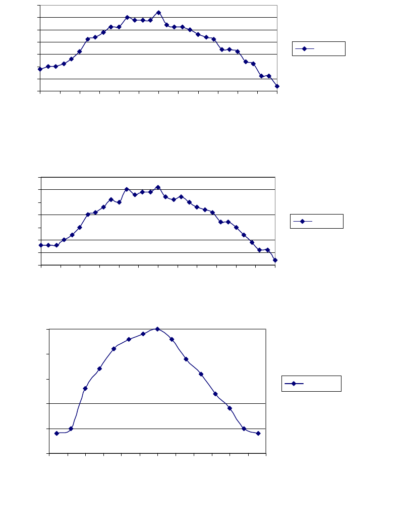
Aurora 5800
165
•
•
•
•
•
•
Wideband Interference
Figure D-9 T/I versus wideband interference frequency offset
(Directions A and B, same code, 05B8)
Figure D-10 T/I versus wideband interference frequency offset
(Direction A: 05B8, Direction B: 3F0C)
Figure D-11 C/I versus wideband interference frequency offset
-20
-15
-10
-5
0
5
10
15
-30-25-20-15-10-5 0 5 1015202530
Interference Frequency Offset (MHz)
T/I (dB)
T/I (dB)
-20
-15
-10
-5
0
5
10
15
-30 -25 -20 -15 -10 -5 0 5 10 15 20 25 30
Interference Frequency Offset
T/I (dB)
T/I (dB)
-20
-15
-10
-5
0
5
-30 -25 -20 -15 -10 -5 0 5 10 15 20 25 30
Interference Frequency Offset (MHz)
C/I (dB)
C/I (dB)
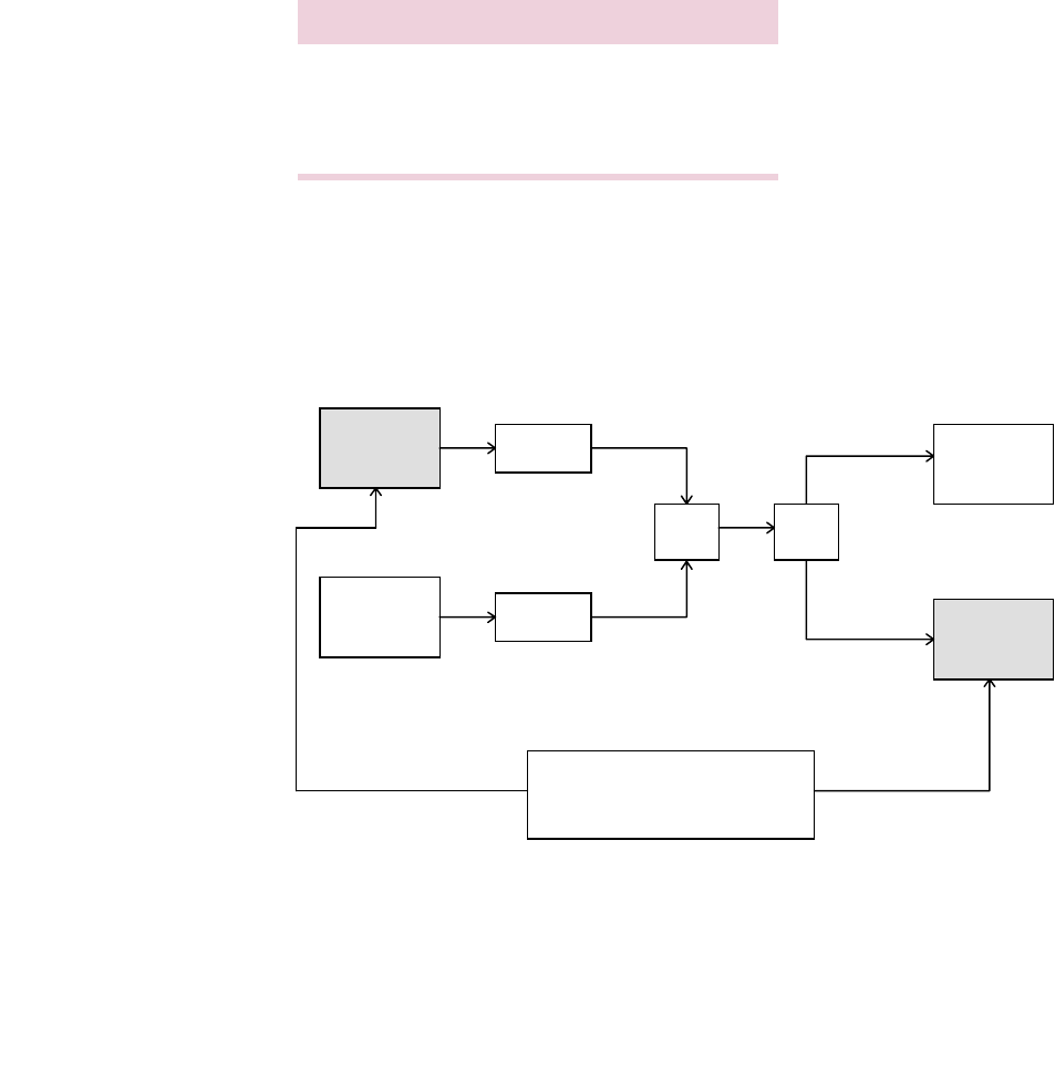
166 Appendix D Typical Radio Performance Results for 2T1
•
•
•
•
•
•
FCC Part 15, Compliance Processing Gain
Performance Test
Test method recommended by FCC 97-114 is the CW Jamming
Margin Method.
Test Setup
Test setup is shown in Figure D-12.
Figure D-12 Processing gain test setup
Characteristic Value
Data rate 2T1 (3.208 Mb/s)
Chip rate 11 chips/bit
Designed processing gain 10.4 dB
HP37701A
Communications
Analyzer
Transmitter Variable
Attenuator
Variable
Attenuator
Comb/
Splitter Comb/
Splitter
HP8648C
Signal
Generator
HP435B
Power
Meter
Receiver
Data In
Data Out

Aurora 5800
167
•
•
•
•
•
•
Jamming Margin (J/S Ratio) (for BER 10-5)
The test was performed in Direction B. 50-kHz increments were used in this
test; the worst 20% were discarded. See Table D-8.
After the worst 20% (64 points marked with (x)) were discarded, the lowest
J/S ratio was
−
1.2 dB (marked with (**)).
Hence
M
j
=
−
1.2 dB.
The S/N ratio for ideal noncoherent receiver is calculated from
Pe = ½ e
(-½ (S/N)
o
)
,
where
Pe =
10
-5
.
Hence
(S/N)
o
= 13.3 dB.
The processing gain can be calculated as
G
p
=
(S/N)
o
+
M
j
+
L
sys
where
L
sys
= System Loss.
No more than 2-dB loss is allowed (we assumed 0 dB).
Hence
G
p
= 13.3
−
1.2 + 0.0 = 12.1 dB, better than the designed coding gain
of 10.4 dB and better than the FCC’s minimum requirement of 10 dB.

168 Appendix D Typical Radio Performance Results for 2T1
•
•
•
•
•
•
Table D-8 Jamming margin (J/S ratio) (for BER 10
-5
) for 2T1
Freq. Offset
(MHz) J/S
(dB) Freq. Offset
(MHz) J/S
(dB) Freq. Offset
(MHz) J/S
(dB) Freq. Offset
(MHz) J/S
(dB)
−
10.00 0.4
−
8.00
−
1.2
−
6.00 (x)
−
1.6
−
4.00 (x)
−
1.5
.05 0.4 .05
−
1.1 .05 (x)
−
1.6 .05 (x)
−
1.4
.10 0.4 .10
−
1.2 .10 (x)
−
1.7 .10 (x)
−
1.3
.15 0.4 .15 (x)
−
1.3 .15 (x)
−
1.7 .15 (x)
−
1.3
.20 0.4 .20 (x)
−
1.7 .20 (x)
−
1.7 .20 (x)
−
1.3
.25 0.4 .25 (x)
−
1.5 .25 (x)
−
1.7 .25 (x)
−
1.3
.30 0.5 .30 (x)
−
1.6 .30 (x)
−
1.7 .30 (x)
−
1.3
.35 0.4 .35 (x)
−
1.7 .35 (x)
−
1.5 .35 (x)
−
1.3
.40 0.3 .40 (x)
−
1.8 .40 (x)
−
1.4 .40 (x)
−
1.3
.45 0.3 .45 (x)
−
1.7 .45 (x)
−
1.3 .45 (x)
−
1.4
.50 0.3 .50 (x)
−
1.7 .50
−
1.2 .50 (x)
−
1.5
.55 0.3 .55 (x)
−
1.8 .55
−
1.2 .55 (x)
−
1.2
.60 0.3 .60 (x)
−
1.8 .60 (x)
−
1.3 .60
−
1.0
.65 0.3 .65 (x)
−
1.8 .65 (x)
−
1.3 .65
−
1.0
.70 0.3 .70 (x)
−
1.8 .70
−
1.2 .70
−
0.9
.75 0.4 .75 (x)
−
1.6 .75
−
1.2 .75
−
0.8
.80 0.5 .80 (x)
−
1.5 .80 (x)
−
1.6 .80
−
0.5
.85 0.4 .85 (x)
−
1.5 .85 (x)
−
1.5 .85
−
0.6
.90 0.3 .90 (x)
−
1.4 .90 (x)
−
1.3 .90
−
0.7
.95 0.2 .95 (x)
−
1.4 .95 (x)
−
1.5 .95
−
0.8
−
9.00 0.1
−
7.00 (x)
−
1.3
−
5.00 (x)
−
1.6
−
3.00
−
0.9
.05
−
0.1 .05 (x)
−
1.3 .05 (x)
−
1.6 .05
−
0.9
.10
−
0.1 .10
−
1.0 .10 (x)
−
1.6 .10
−
0.9
.15
−
0.2 .15
−
1.1 .15 (x)
−
1.5 .15
−
1.0
.20
−
0.2 .20
−
1.1 .20 (x)
−
1.6 .20 (x)
−
1.2
.25
−
0.1 .25
−
1.2 .25 (x)
−
1.7 .25 (x)
−
1.2
.30
−
0.1 .30
(**)
−
1.2
.30 (x)
−
1.7 .30 (x)
−
1.2
.35
−
0.1 .35
−
1.1 .35 (x)
−
1.6 .35
−
1.1
.40 0.0 .40
−
1.1 .40 (x)
−
1.6 .40
−
1.0
.45
−
0.1 .45 (x)
−
1.3 .45 (x)
−
1.6 .45
−
1.0
.50
−
0.2 .50 (x)
−
1.4 .50 (x)
−
1.6 .50
−
0.9
.55
−
0.2 .55 (x)
−
1.3 .55 (x)
−
1.7 .55
−
0.6
.60
−
0.3 .60 (x)
−
1.4 .60 (x)
−
1.7 .60
−
0.3
.65
−
0.3 .65 (x)
−
1.6 .65 (x)
−
1.6 .65
−
0.5
.70
−
0.4 .70 (x)
−
1.7 .70 (x)
−
1.7 .70
−
0.7
.75
−
0.4 .75 (x)
−
1.7 .75 (x)
−
1.3 .75
−
0.4
.80
−
0.4 .80 (x)
−
1.7 .80
−
0.7 .80
−
0.3
.85
−
0.4 .85 (x)
−
1.5 .85 (x)
−
1.6 .85
−
0.2
.90
−
0.6 .90 (x)
−
1.4 .90 (x)
−
1.9 .90
−
0.1
.95
−
0.6 .95 (x)
−
1.5 .95 (x)
−
1.7 .95
−
0.1

Aurora 5800
169
•
•
•
•
•
•
−
2.00
−
0.1 0.00 1.0 +2.00 1.3 +
4.00 1.5
.05
−
0.2 .05 0.9 .05 1.3 .05 1.6
.10
−
0.3 .10 0.9 .10 1.4 .10 1.5
.15
−
0.2 .15 0.8 .15 1.3 .15 1.4
.20
−
0.1 .20 0.7 .20 1.3 .20 1.5
.25
−
0.1 .25 0.9 .25 1.3 .25 1.4
.30
−
0.1 .30 1.1 .30 1.3 .30 1.3
.35 0.0 .35 0.9 .35 1.4 .35 1.3
.40 0.1 .40 0.8 .40 1.2 .40 1.2
.45 0.0 .45 1.0 .45 1.2 .45 1.2
.50 0.0 .50 1.2 .50 1.3 .50 1.1
.55
−
0.2 .55 1.1 .55 1.1 .55 1.1
.60
−
0.4 .60 1.0 .60 1.0 .60 1.2
.65
−
0.4 .65 1.0 .65 1.1 .65 1.2
.70
−
0.4 .70 1.0 .70 1.2 .70 1.2
.75
−
0.5 .75 0.9 .75 1.3 .75 1.3
.80
−
0.7 .80 0.8 .80 1.4 .80 1.4
.85
−
0.7 .85 0.6 .85 1.2 .85 1.4
.90
−
0.7 .90 0.4 .90 1.3 .90 1.5
.95
−
0.4 .95
−
0.1 .95 1.4 .95 1.4
−
1.00
−
0.2 +1.00
−
0.2 +3.00 1.5 +5.00 1.3
.05
−
0.2 .05
−
0.1 .05 1.5 .05 1.7
.10
−
0.1 .10
−
0.6 .10 1.5 .10 1.8
.15 0.0 .15 0.1 .15 1.5 .15 1.7
.20 0.1 .20 0.2 .20 1.6 .20 1.7
.25 0.2 .25 0.3 .25 1.7 .25 1.7
.30 0.3 .30 0.4 .30 1.6 .30 1.6
.35 0.3 .35 0.5 .35 1.5 .35 1.8
.40 0.4 .40 0.7 .40 1.6 .40 2.0
.45 0.5 .45 0.8 .45 1.6 .45 1.7
.50 0.6 .50 1.0 .50 1.6 .50 1.6
.55 0.4 .55 1.0 .55 1.7 .55 1.7
.60 0.2 .60 1.1 .60 1.8 .60 1.6
.65 0.3 .65 0.6 .65 1.7 .65 1.6
.70 0.5 .70 0.3 .70 1.8 .70 1.7
.75 0.7 .75 0.5 .75 1.6 .75 1.8
.80 0.9 .80 1.1 .80 1.7 .80 1.8
.85 0.8 .85 1.1 .85 1.7 .85 1.7
.90 0.7 .90 1.1 .90 1.8 .90 1.8
.95 0.8 .95 1.2 .95 1.7 .95 1.8
Freq. Offset
(MHz) J/S
(dB) Freq. Offset
(MHz) J/S
(dB) Freq. Offset
(MHz) J/S
(dB) Freq. Offset
(MHz) J/S
(dB)
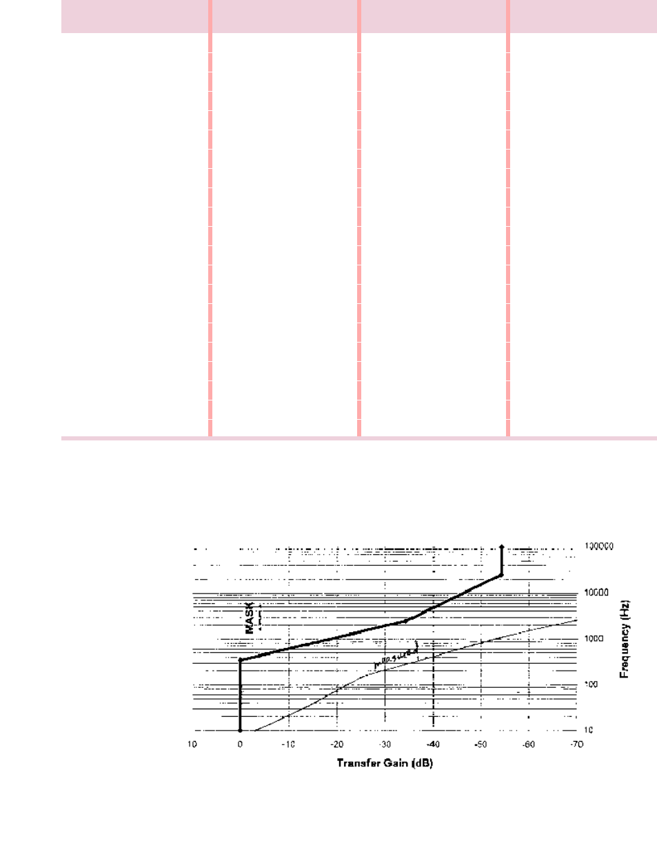
170 Appendix D Typical Radio Performance Results for 2T1
•
•
•
•
•
•
Jitter Transfer Function
Figure D-13 Jitter transfer (DS1)
+
6.00 1.8
+7
.00 3.2
+8
.00 3.8
+9
.00 6.7
.05 1.8 .05 3.1 .05 4.1 .05 6.8
.10 1.8 .10 3.0 .10 4.6 .10 7.1
.15 2.0 .15 3.0 .15 5.2 .15 7.2
.20 2.1 .20 3.0 .20 6.0 .20 7.4
.25 2.0 .25 3.1 .25 6.0 .25 7.4
.30 1.9 .30 3.1 .30 5.2 .30 7.3
.35 1.9 .35 2.8 .35 5.3 .35 7.7
.40 1.9 .40 2.5 .40 5.5 .40 7.9
.45 2.2 .45 2.6 .45 5.6 .45 8.0
.50 2.6 .50 2.8 .50 5.7 .50 6.9
.55 2.5 .55 2.5 .55 5.7 .55 8.2
.60 2.5 .60 2.2 .60 5.8 .60 8.0
.65 2.7 .65 2.4 .65 5.8 .65 8.1
.70 3.0 .70 2.5 .70 5.9 .70 8.2
.75 2.9 .75 3.0 .75 6.0 .75 8.8
.80 2.7 .80 3.3 .80 6.2 .80
9.2
.85 2.7 .85 3.3 .85 6.4 .85
9.2
.90 2.8 .90 3.2 .90 6.6 .90
9.2
.95 2.9 .95 3.5 .95 6.6 .95
9.8
+10.00 10.2
Freq. Offset
(MHz) J/S
(dB) Freq. Offset
(MHz) J/S
(dB) Freq. Offset
(MHz) J/S
(dB) Freq. Offset
(MHz) J/S
(dB)

Aurora 5800
171
•
•
•
•
•
•
Environmental Performance
Temperature Performance
Direction B, Code: 05B8
Long-Term Error Performance
Receiver input level is set at the nominal
−
40 dBm at room temperature.
Both transmitter and receiver achieved error-free performance over
temperature cycling for 0
o
C to +50
o
C for continuous 8-hour testing.
Power Consumption Measurement
Input: 110 VAC
Power consumed: 21 watts
Temperature
(°C) Tx Power
(dBm) Rx Threshold
(dBm)
019.2
−
90
25 19.0
−
89
50 18.7
−
87.5

172 Appendix D Typical Radio Performance Results for 2T1
•
•
•
•
•
•
This page intentionally blank.
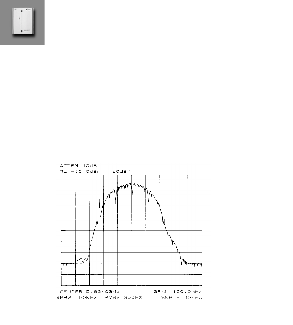
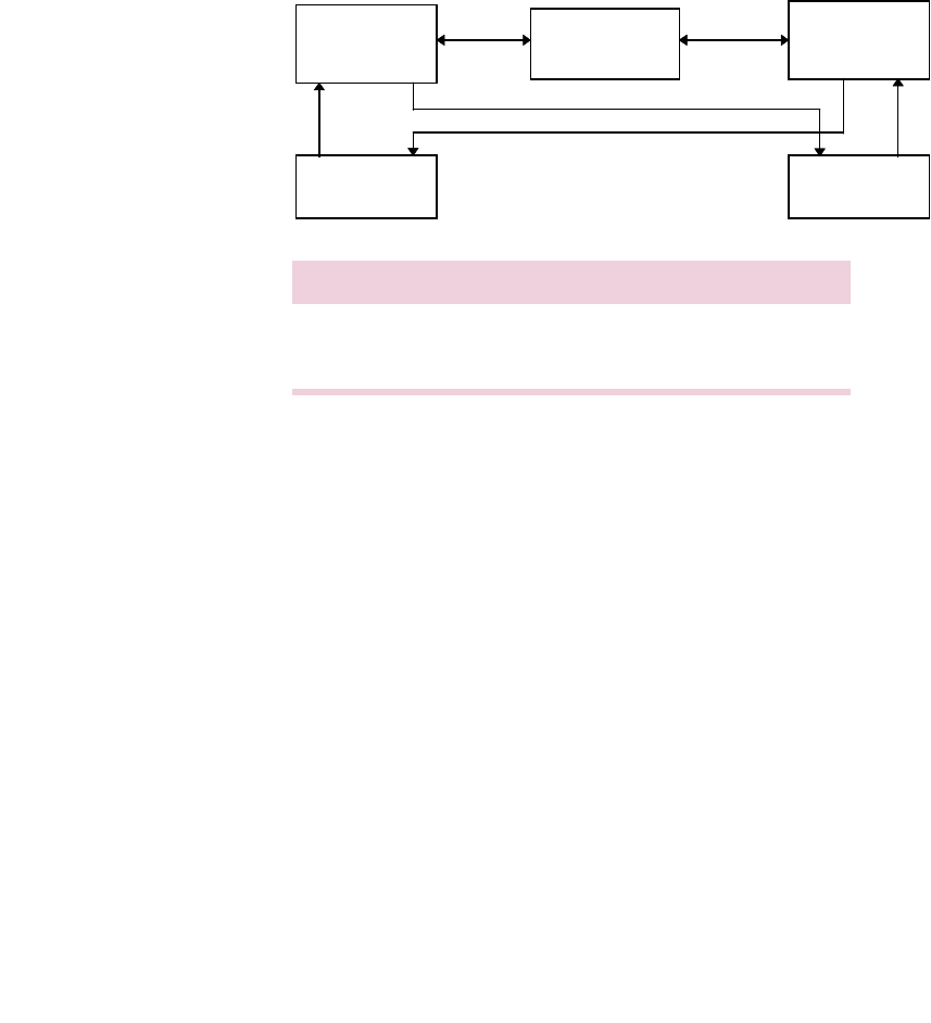
174 Appendix E Typical Radio Performance Results for 2E1
•
•
•
•
•
•
Receiver Tests
Test Setup
Figure E-2 Receiver test setup
Receiver Sensitivity
Code used: 05B8
Requirement:Input threshold at BER 10
-6
≤ −85
dBm
Results: Both directions use same spread sequence.
Direction Transmit Receive
A Radio 1 at 5772 MHz Radio 2 at 5772 MHz
B Radio 2 at 5834 MHz Radio 1 at 5834 MHz
40 to 130 dB
Radio 1 Variable
Attenuator Radio 2
BERT BERT

Aurora 5800
175
•
•
•
•
•
•
Table E-1 Receiver sensitivity
Dispersive Fade Margin
Test Conditions
Direction A code: 05B8
Direction B code: 05B8
Fade simulator is inserted in the 140-MHz IF path.
RCV input level is at nominal - 40 dBm.
Direction A
See Table E-2 and Table E-3 for the results of this test for Direction A.
Direction Rx Input
(dBm) At
A
−
88 BER = 1E-6
−
93 Sync loss
−
92 Re-acquisition
B
−
87 BER = 1E-6
−93
Sync loss
−92
Re-acquisition

176 Appendix E Typical Radio Performance Results for 2E1
•
•
•
•
•
•
Table E-2 Direction A, minimal phase
Table E-3 Direction A, non-minimal phase
Notch
Frequency
(MHz)
Notch Depth
(dB)
at BER 1E-6
Notch Depth
(dB)
at BER 1E-3
Notch Depth
(dB)
at Sync Loss
Notch Depth
(dB)
at Re-acquisition
132 40 at 132.4 MHz
134 32.8 > 40
136 28.5 33.0 > 40 > 40
138 25.0 29.0 > 40 > 40
140 26.0 30.0 > 40 > 40
142 23.7 32.0 > 40 > 40
144 20.5 > 40 > 40 > 40
146 20.4
148 30.0
40 at 149.5 MHz
Notch
Frequency
(MHz)
Notch Depth
(dB)
at BER 1E-6
Notch Depth
(dB)
at BER 1E-3
Notch Depth
(dB)
at Sync Loss
Notch Depth
(dB)
at Re-acquisition
132 > 40
134 > 40
136 > 40 > 40
138 > 40 > 40
140 > 40 > 40
142 22.2 > 40
144 19.4 > 40
146 18.0
148 22.0
40 at 149 MHz
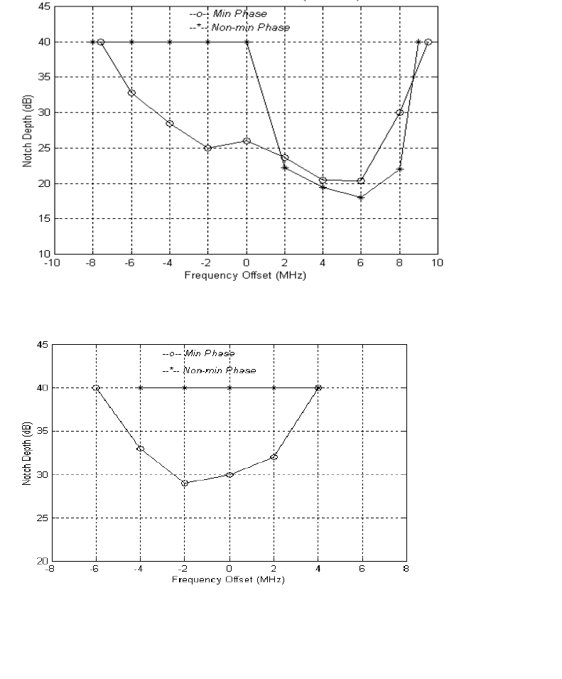

178 Appendix E Typical Radio Performance Results for 2E1
•
•
•
•
•
•
Direction B
See Table E-4 and Table E-5 for the results of this test for Direction B.
Table E-4 Direction B, minimal phase
Table E-5 Direction B, non-minimal phase
DFM = 67.34 dB for BER = 1E-6
DFM = 76.3 dB for BER = 1E-3
Notch
Frequency
(MHz)
Notch Depth
(dB)
at BER 1E-6
Notch Depth
(dB)
at BER 1E-3
Notch Depth
(dB)
at Sync Loss
Notch Depth
(dB)
at Re-acquisition
136 > 40
138 > 40 > 40
140 > 40 > 40
142 33 > 40
144 36
146 > 40
Notch
Frequency
(MHz)
Notch Depth
(dB)
at BER 1E-6
Notch Depth
(dB)
at BER 1E-3
Notch Depth
(dB)
at Sync Loss
Notch Depth
(dB)
at Re-acquisition
136 > 40
138 > 40 > 40
140 > 40 > 40
142 39 > 40
144 25
146 > 40
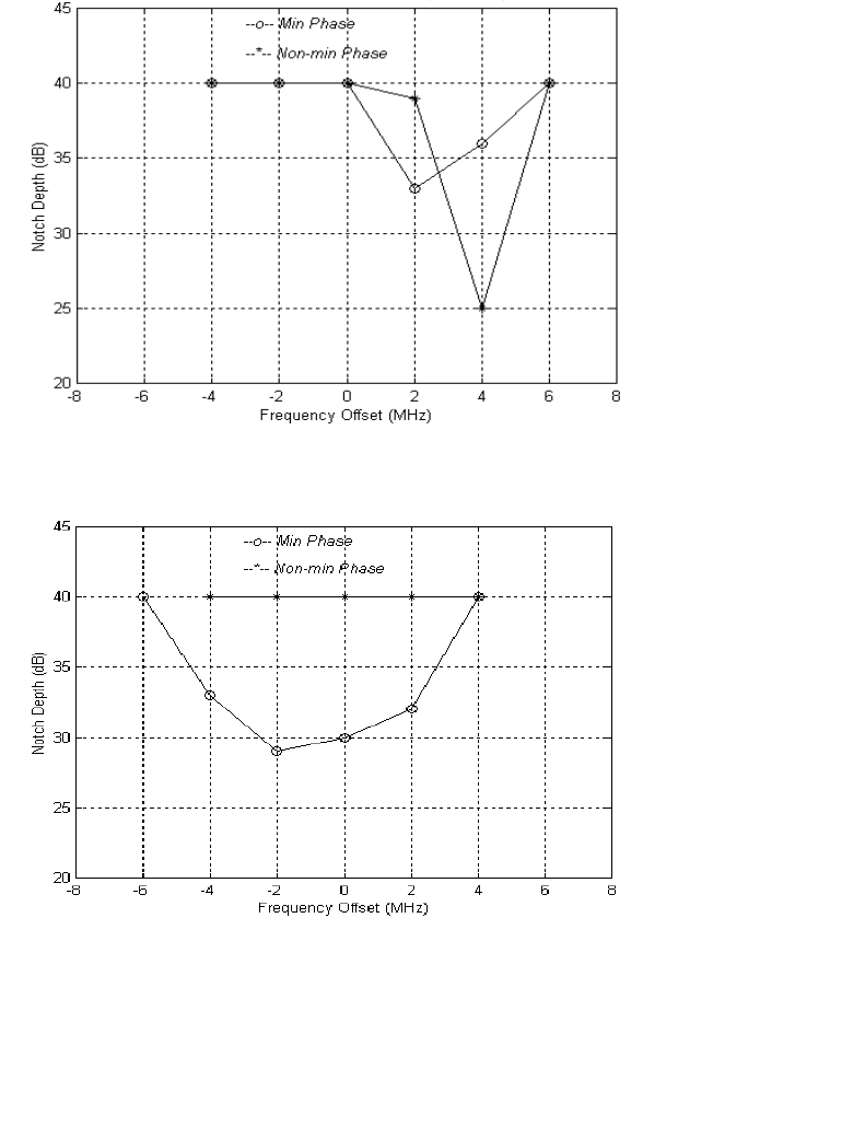

180 Appendix E Typical Radio Performance Results for 2E1
•
•
•
•
•
•
Dynamic Fading
Sweep Notch Depth Range
Table E-6 Sweep notch depth range for ultimate error-free region
(elapse time: 0.1 sec)
Sweep Notch Frequency
Table E-7 Checking for error notch depth region, elapse time: 0.1 sec
(equivalent to sweep speed 600 MHz/sec)
Flat Fading
Sweep for ultimate error-free attenuation range (flat fading), elapse time:
0.1 sec.
Note
: Attenuation is inserted in the IF path. RF AGC is disabled. Only the
dynamic performance of the IF AGC is tested.
Direction A: 0 to 61 dB
Direction B: 0 to 62 dB
Notch
Frequency
(MHz)
Direction A Notch Depth
(dB) Direction B Notch Depth
(dB)
Minimal
Phase Non-minimal
Phase Minimal
Phase Non-minimal
Phase
135.0 0 to 31 0 to > 40 0 to 24 0 to > 40
140.0 0 to 27 0 to > 40 0 to 29 0 to > 40
145.0 0 to 18 0 to 18 0 to 31 0 to 25
Notch
Frequency
(MHz)
Direction A Notch Depth
(dB) Direction B Notch Depth
(dB)
Minimal
Phase Non-minimal
Phase Minimal
Phase Non-minimal
Phase
115 to 165 19.0 19.0 22.0 24.0

Aurora 5800
181
•
•
•
•
•
•
Interference Performance
The effect of an interfering signal into a digital radio receiver is
characterized by a 1-dB degradation in the BER
=
1
×
10
-6
(static) and
1
×
10
-3
(outage) thresholds. The standard for this characteristic is the
threshold-to-interference (T/I) ratio, as defined in EIA/TIA Document
TSB-10-F. [Ref 5]
The test was performed for sinewave (narrowband) interference and for like
signal (wideband) interference. The method used in this test follows the TIA
Bulletin TSB-10-F Standard T/I measurement recommendation.
The C/I uses nominal receiver input level (
−
40 dBm), and then interference
is injected to get a BER of 10
-6
. C/I is the ratio of the signal to interference
ratio at this point, measured in direction A only.
See Figure E-7 to Figure E-11.
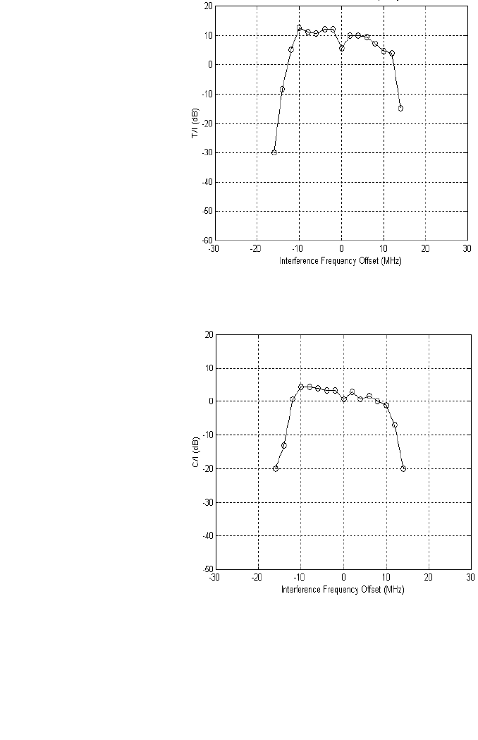
182 Appendix E Typical Radio Performance Results for 2E1
•
•
•
•
•
•
Narrowband Interference
Figure E-7 T/I versus narrowband interference frequency offset
Figure E-8 C/I versus narrowband interference frequency offset
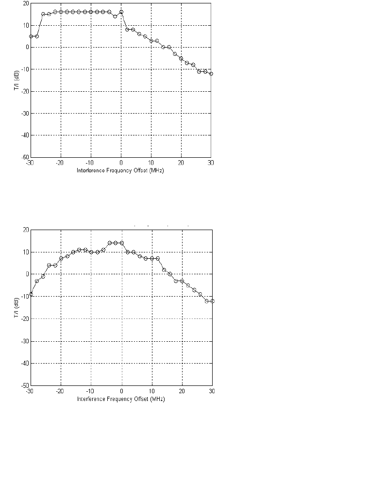
Aurora 5800
183
•
•
•
•
•
•
Wideband Interference
Figure E-9 T/I versus wideband interference frequency offset
(Directions A and B, same code, 05B8)
Figure E-10 T/I versus wideband interference frequency offset (Direction
A: 05B8, Direction B: 0247)
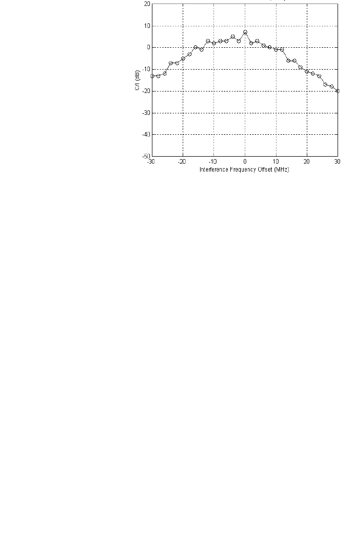
184 Appendix E Typical Radio Performance Results for 2E1
•
•
•
•
•
•
Figure E-11 C/I versus wideband interference frequency offset

Aurora 5800
185
•
•
•
•
•
•
Jitter Performance
Input Jitter Tolerance
HDB3 input ports were tested according to ITU-T Rec. G.823, Table 2
(2
15
-1 pseudorandom test signal used).
Table E-8 Test results, input jitter tolerance
The input jitter tolerance complies with Figure 3/G.823 and Table 2/G.823
requirements.
Output Jitter
The output jitter complies with Figure 4/G.823 and Table 3/G.921 (same
pseudorandom test signal used as in preceding test). The output jitter in the
absence of input jitter frequency in the range f
0
to f
4
, is less than 0.1 UI
p-p
;
Table 3/G.921 allows for 0.2 UI
p-p
.
Jitter Gain
The jitter gain in the frequency range, f
0
to f
4
, is far below (worst case,
−
4 dB) the limit of 3 dB specified in Section 1.3.2.3/G.921.
Test
Frequency Jitter Frequency
(Hz)
Tolerable Input Jitter
(UI
p-p
)G.823 Lower Limit
(UI
p-p
)
f
0
1.2
×
10
-5
> 40 36.9
f
1
20 10 1.5
f
2
2.4 k 10 1.5
f
3
18 k 3.6 0.2
f
4
100 k 0.7 0.2

186 Appendix E Typical Radio Performance Results for 2E1
•
•
•
•
•
•
Jitter Transfer Characteristic
Table E-9 shows that test results exceeded the standards of Figure 4/G.823
and AT&T 62411.
Table E-9 Test results, jitter transfer characteristic
Environmental Performance
Temperature Performance
Long-Term Error Performance
Receiver input level is set at the nominal
−
40 dBm at room temperature.
Both transmitter and receiver achieved error-free performance over
temperature cycling for 0
o
C to +50
o
C for continuous 8-hour testing.
Test
Frequency Jitter Frequency
(Hz) Jitter Attenuation
(dB)
AT&T 62411
Upper Limit
(dB)
f
0
1.2
×
10
-5
4.0 0
f
5
20 28.0 0
f
6
2 k 45.0 40
> 2 k > 45.0 40
Temperature
(°C) Tx Power
(dBm) Rx Threshold
(dBm)
019.2
−
89
25 19.0
−
88
50 18.7
−
87.5


188 Appendix F Forms
•
•
•
•
•
•
This page intentionally blank.

Harris Microwave Communications Division
Service Registration Form
To facilitate warranty support and to receive product update information, please complete and
return this form to our customer service department.
By fax:
514-421-3555
By e-mail:
crcmtl@harris.com
By mail:
Harris Corporation
Microwave Communications Division
3 Hotel de Ville
Dollard-des-Ormeaux, Quebec
CANADA H9B 3G4
Attention: Customer Resource Center
The Customer Resource Center is available on the internet at http://www.microwave.harris.com/cservice/.
Please print:
Company Name: _____________________________________
Requester’s Name: ___________________________________
Title________________________________________________ Dept. _____________________________
Address
City_________________________________________ State/Province_____________________________
ZIP/Postal Code ______________________________ Country__________________________________
Telephone Number ____________________________ Fax Number ______________________________
E-mail_______________________________________
Original Sales Order/PO Number________________
(Sales order number is found in your documentation and on the equipment rack base plate.)

Harris Microwave Communications Division
Rapid Request for Return Material Authorization (RMA)
Service Locations:
5727 Farinon Drive or 3, Hotel de Ville, Dollard-des-Ormeaux
San Antonio, TX 78249, USA Quebec, CANADA H9B 3G4
Tel: 1-800-227-8332 or 1-800-465-4654, (+1) 514-421-8333
Fax: (+1) 514-421-3555
The Customer Resource Center is available on the internet at http://www.microwave.harris.com/cservice/.
Company Name:_____________________________ Phone: ______________________________________
Requester’s Name: __________________________ Fax:_________________________________________
Billing Address Shipping Address
____________________________________________ _____________________________________________
____________________________________________ _____________________________________________
____________________________________________ _____________________________________________
Service Requested: [ ] Repair [ ] Exchange
Requested Repair Urgency: [ ] Standard [ ] Expedite
Warranty Status: [ ] IN-WARR (Provide Sales Order No.) _______________________________
[ ] NON-WARR (Provide Purchase Order No.) _________________________
Requested Mode of Shipment: [ ] Standard Service [ ] 2nd Day Air [ ] Overnight
NOTE: IN-WARRANTY UNITS are returned via STANDARD SERVICE only. Please provide COURIER ACCOUNT
NUMBER if faster delivery is required.________________________________________________________________
SD Number and Options Part Description Problem/Service Required
________________________ _____________________________ ________________________________
________________________ _____________________________ ________________________________
________________________ _____________________________ ________________________________
________________________ _____________________________ ________________________________
________________________ _____________________________ ________________________________
Special Instructions
_______________________________________________________________________________________________
_______________________________________________________________________________________________
_______________________________________________________________________________________________
Please do not write below this space
Date Form Received: ____________________ Rec by: _________________________ Your RMA # is: ________
Repair/Exchange Price: Item 1_______________________ Item 4 _______________________
Item 2_______________________ Item 5 _______________________
Item 3_______________________ Item 6 _______________________
Harris MCD Instruction Manual Survey
1. Overall, taking everything into account, how would you rate
this Harris MCD instruction manual (IM)?
(check one box)
Excellent Fair
Very Good Poor
Good
2. How do you think this Harris MCD IM compares with the
instruction manuals provided by other manufacturers of microwave
radio assemblies?
(check one box)
Better than other instruction manuals.
About the same as other instruction manuals.
Worse than other instruction manuals.
3. If you have the printed version of the Harris MCD IM, please
rate the following characteristics.
(check one box per characteristic)
Very
Excellent Good Good Fair Poor
Binding
Section tabs
Printing
Type style
Text format
Page layout
4. If you have the CD-ROM version of the Harris MCD IM,
please rate the following characteristics.
(check one box per
characteristic)
Very
Excellent Good Good Fair Poor
Ease of installation
Hypertext links
Legibility
Text format
Page layout
5. Using the same scale as in question 3 or 4, please rate each of
the following characteristics as they relate to the context of this
Harris MCD IM.
(check one box per characteristic)
Very
Excellent Good Good Fair Poor
Organization
Clarity
Completeness
Correctness
6. Using the same scale once again, please rate each of the
following characteristics as they relate to the diagrams, illustrations,
charts, graphs, tables, and figures in this Harris MCD IM.
(check one
box per characteristic)
Very
Excellent Good Good Fair Poor
Organization
Clarity
Completeness
Correctness
7. Please rate the following sections of this Harris MCD IM.
(check one box per characteristic)
Very
Excellent Good Good Fair Poor
Table of contents
General information
Installation section
Operation procedure
Alignment section
Routine maintenance
Trouble isolation
Unit replacement
Appendixes
Index
8. What is there about this Harris MCD IM that you like?
(please
be specific)
9. On the other hand, what is there about this Harris MCD IM that
you dislike?
(please be specific)
10. Which of the following comes closest to describing your title?
(check one box)
Technician Communications Tech
Engineer Operations Manager
Other (specify):
Please complete the following information.
After completing this form, fold (see reverse side), seal, and mail
to Harris MCD. No postage required if mailed in the United
States.
IM Part No.: Issue:
Product:
Your Name:
Your Title:
Company:
Address:
NO POSTAGE
NECESSARY IF
MAILED IN THE
UNITED STATES
BUSINESS REPLY MAIL
FIRST CLASS MAIL. PERMIT NO. 241, SAN CARLOS, CA
POSTAGE WILL BE PAID BY ADDRESSEE
HARRIS CORPORATION
MICROWAVE COMMUNICATIONS DIVISION
ATTN: TECHNICAL PUBLICATIONS
350 TWIN DOLPHIN DRIVE
REDWOOD SHORES CA 94065-1421
FOLD HERE
FOLD HERE
SEAL WITH TAPE BEFORE MAILING

Aurora 5800
195
•
•
•
•
•
•
• • • • • •
Glossary
AC
Alternating Current.
ACU
Antenna Coupling Unit.
A/D
Analog to Digital.
ADPCM
Adaptive Differential Pulse Code Modulation.
AGC
Automatic Gain Control; automatic gain adjustment of a varying input
signal level to produce a constant output signal level.
AIS
Alarm Indication Signal.
ALC
Automatic Level Control.
AMI
Alternate Mark Inversion.

196 Glossary
•
•
•
•
•
•
ANSI
American National Standards Institute.
antenna feed system
A system that transports signals from the output terminal of the transmitter
to the antenna or to the antenna radiator. It usually consists of the
transmitter-antenna feed connector, the antenna feed, and the antenna
mechanical structure, such as a tower, mast, and radiator support, and does
not include the antenna or the radiator and reflector, if any.
B8ZS
Bipolar with Eight Zero Substitution.
baseband
A frequency band occupied by a modulating information signal.
Bellcore
Bell Communications Research, Inc. (source of telephony standards in the
U.S.A.).
BER
Bit Error Ratio.
BERT
Bit Error Ratio Tester.
BPF
BandPass Filter.
BSC
Base Station Controller.
BW
BandWidth.

Aurora 5800
197
•
•
•
•
•
•
CAN
Controller Area Network, an interface standard (ISO 11898) for
interconnecting microcontrollers.
CEPT
Conference Européen des Administrations des Postes et des
Télécommunications.
C/I
Carrier-to-Interference (ratio).
CIT
Craft Interface Terminal.
CRC
Customer Resource Center.
CW
Continuous Wave.
DC
Direct Current.
demux
demultiplexer.
DFM
Dispersive Fade Margin.
DIP
Dual In-line Package (switch).
directivity
The distribution in space of the energy radiated by an antenna.

198 Glossary
•
•
•
•
•
•
DMM
Digital MultiMeter.
DQPSK
Differential Quadrature Phase-Shift Keying.
DSSS
Direct Sequence Spread Spectrum.
D-subminiature connectors
The size of the D-subminiature connector is specified by the standard shell
size and the number of connectors. For example, a 15-pin connector is
referred to as a DA-15. See the following table.
DTE
Data Terminal Equipment.
EEPROM
Electronically Erasable Programmable Read-Only Memory.
EIA
Electronic Industries Association.
EIRP
Effective Isotropic Radiated Power.
Standard Shell Size No. of Connectors
E9
A15
B25
C37
D50

Aurora 5800
199
•
•
•
•
•
•
ETSI
European Telecommunications Standards Institute.
FarScan
Harris’ network management system software.
FCC
Federal Communications Commission (U.S.).
FM
Fade Margin; Frequency Modulation.
FPGA
Field-Programmable Gate Array.
hop
The span between a transmitter and a receiver.
IF
Intermediate Frequency; frequency below the radio frequency.
IM
Instruction Manual.
ISM
Industrial, Scientific, and Medical.
ISO
International Organization for Standardization.
ITU
International Telecommunication Union.

200 Glossary
•
•
•
•
•
•
J/S
Jamming-to-Signal (ratio).
LAN
Local Area Network.
LED
Light-Emitting Diode.
LNA
Low-Noise Amplifier.
LO
Local Oscillator.
LOS
Loss Of input data Signal.
MCD
Microwave Communications Division, formerly Farinon Division.
MCU
MicroController Unit.
MMIC
Microwave Monolithic Integrated Circuit.
MSC
Mobile Switch Center.
MTBF
Mean Time Between Failures.
mux
multiplexer.

Aurora 5800
201
•
•
•
•
•
•
NC
Normally Closed.
NCO
Numerically Controlled Oscillator.
NMS
Network Management System.
NO
Normally Open.
NRZ
NonReturn to Zero (coding).
OEM
Original Equipment Manufacturer.
PA
Power Amplifier.
PCB
Printed Circuit Board.
PCN
Personal Communications Network.
PCS
Personal Communications Service.
PLL
Phase-Locked Loop.
PN
Pseudo-random Number.

202 Glossary
•
•
•
•
•
•
QPSK
Quadrature Phase-Shift Keying.
RF
Radio Frequency.
RMA
Return Material Authorization.
RMS
Rack-Mounting Space.
ROM
Read-Only Memory.
RSL
Received Signal Level.
RSSI
Receive Signal Strength Indicator.
RX
Receiver.
SAW
Surface Acoustic Wave.
SCAN
System Control And Alarm Network. Harris’ proprietary standard for
sending alarm/status/control messages over a serial port.
SD
Schematic Drawing.

Aurora 5800
203
•
•
•
•
•
•
SESR
Severe Errored-Second Ratio.
SNMP
Simple Network Management Protocol.
SPSC
Spare Products Support Center.
TCXO
Temperature-Compensated Crystal Oscillator.
T/I
Threshold-to Interference (ratio).
TIA
Telecommunication Industries Association.
TX
Transmitter.
VCO
Voltage-Controlled Oscillator.
VGA
Variable Gain Amplifier.
WAN
Wide Area Network.
XO
Crystal Oscillator.

204 Glossary
•
•
•
•
•
•
This page intentionally blank.

Aurora 5800
205
•
•
•
•
•
•
• • • • • •
References
1. Docherty, “Why Microwave Makes Sense for Short Haul Transport in
Cities”, 5/96, Harris Technical Doc. No. 117.
2. R. U. Laine and A. R. Lunan, “Digital Microwave Link Engineering–
Performance Definitions and Objectives”, ENTELEC ’94, San Antonio, TX,
3/94. Harris Technical Doc. No. 215.
3. A. R. Lunan, W. Shaw, “Aurora 2400 Multipath Reliability and Distance
Charts”, 8/98, Harris Technical Doc. No. 220.
4. StarLink personal computer program for the Windows operating system,
available free of charge from Harris Corporation. See www.harris.com,
Microwave Communications/StarLink Internet page.
5. TIA/EIA Telecommunications Systems Bulletin TSB-10-F, “Interference
Criteria for Microwave Systems”, Washington, DC, 5/95.

206 References
•
•
•
•
•
•
This page intentionally blank.

Aurora 5800
207
•
•
•
•
•
•
• • • • • •
Index
A
acquisition time 58
address, to order spare parts 104
alarm and status levels 90
loss of signal 90
alarm port 29
antenna
alignment 80
cable selection 79
connector 27
cross-polarized 49
dual-polarized 49
flat panel 75
parabolic 52
performance 75
selection criteria 75
single-polarized 49
site selection 77
Antenna Diplexer 32, 40
antenna feed system 49
antenna/diplexer
frequency spacing 61
specifications 61
antennas, cost savings 76
Aurora 5800 23
back view 27
front view 25

208 Index
•
•
•
•
•
•
B
backside interference 50
blocking arrangement 52
built-in diagnostics 69
C
CAN microcontroller 35
carrier-to-interference ratio 49, 51
cellular system 23
chip rate 59
CIT 23
interface 57
pinout 30
port 34
COMM port connection 92
configuration button 91
correlated path fading 51
Customer Resource Center 21
Customer Service Center locations 20
customer training 22, 108
D
damages, limitation of 110
data capacity 62
DATA port 34, 102
pinouts 30
deployment, urban areas 71
diagnostics, built-in 69
direct sequence spread spectrum 23
directivity 75
dispersive fade margin 59, 76
2E1 175
2T1 157
T1 126
test 143
Down Converter 32, 39
nominal frequencies 40
dynamic fading
2E1 180
2T1 162
E1 148
T1 131
E
E1 jitter 66
pulse shape 65
specifications 65
environmental specifications 69
environmental test
2E1 186
2T1 171
E1 153
T1 140
evaluation fee 105
F
fade margin 83
FarScan 23, 24, 101
flat fading
2E1 180
2T1 162
E1 148
T1 132
formInstruction Manual Survey 193
RMA 191
Service Registration 189
frequency
dialog box 93
pairs 23
plan 43, 58

Aurora 5800
209
•
•
•
•
•
•
G
gain 75
H
Harris MCD Instruction Manual Survey
187
hubbing examples 52
hubbing network 50
hybrid couplers 49
I
independent path fading 51
input power connector 27
interference 71, 100
mitigating 72
narrowband
2E1 182
E1 149
wideband
2E1 183
E1 150
interference mechanisms 50
interference performance
2E1 181
2T1 163
E1 149
T1 132
Internet address
Harris Corporation 22
Internet service 23
ISM frequency band 23
J
jamming margin
2T1 167
T1 137
jitterE1 66
gain2E1 185
E1 152
input
2E1 185
E1 152
output
2E1 185
E1 152
performance test
E1 152
performance test, 2E1 185
T1 63
transfer characteristic
2E1 186
E1 153
jitter transfer function
2T1 170
T1 140
L
LAN/WAN 23
leased-line services 72
LED indicators 68
liability, Harris’ 110
licensing procedure
Industry Canada 24
licensing requirement 71
link performance 76
link reliability 77
long-term error performance
2E1 186
E1 153
T1 140, 171
LOS alarm 99
Low-Noise Amplifier 39

210 Index
•
•
•
•
•
•
M
mailing address, spare parts 104
main window 89
mechanical specifications 70
modem 32
block diagram 33
DIP switch settings 38
jumper settings 36
module exchange 105
MTBF 59
multihop network 49
multihopping and hubbing links 48
N
narrowband interference
2T1 164
T1 133
network management systems channel 23
network planning 49
O
outdoor installation 24
output power dialog box 94
P
parallel-path arrangement 49
path clearance 77
PCS/PCN system 23
point-to-point configuration 24, 45
point-to-point path analysis 81
polarization 76
ports 68
power adjust 71
Power Amplifier 39
power consumption
2T1 171
E1 154
T1 140
power specifications 69
Power Supply 32
processing gain performance test
2T1 166
T1 136
product support 103
programmability 68
protection channel 49
protection planning 77
pseudo-random number 44
R
rack spacing requirement 85
RBER 72, 73
received signal level 83
receiver
level 60
specifications 60
receiver sensitivity
2T1 157
T1 125
receiver test setup
2E1 174
2T1 156
E1 142
T1 124
reliability standards 73
repair and return 19, 104
repair service locations 107
repeater configuration 24, 46
repeaters 49
return freight 106

Aurora 5800
211
•
•
•
•
•
•
return material authorization 106
RJ-11 pinout 31
RJ-48C pinout 28
RMA Form 187
Routine Maintenance Log form 187
RS-232 29
RSSI
voltage 80, 97, 98
voltage table 80
running the software 88
RX ALM LED 98
RX Low Noise Amplifier 32
S
SCAN channel 23
Service Registration form 187, 189
site selection 76
SNMP manager 23
SNMP network management 57
software utility
how to install 87
monitor the built-in alarms and status
indicators 87
program 87
spare parts ordering 104
spread code dialog box 94
spread sequence 44
standard product warranty terms 108
StarLink computer program 77
sweep notch depth range
2E1 180
2T1 162
E1 148
sweep notch frequency
2E1 180
E1 148
system gain 58
T
T1 jitter 63
pulse shape 62
specifications 62
T1/E1 interface 28
Technical Support 21
temperature test
2E1 186
2T1 171
E1 153
T1 140
test jacks 68
training centers 22
transmission delay 58
transmit RF spectrum
2T1 155
T1 123
transmitter specifications 59
troubleshooting guideline 97
TX ALM LED 98
TX Power Amplifier 32
TX power dialog box 94
U
unrepairable units 105
Upconverter 32, 39
nominal frequencies 40
utility program 87
V
voice orderwire 32
voice orderwire channel 34, 35
voice/data orderwire 23
