Harris RF Communications Division RF-7800W-G2 The device is to be used in fixed and nomadic infrastructure for Ethernet data backhaul. User Manual Revised Draft
Harris Corporation RF Communications Division The device is to be used in fixed and nomadic infrastructure for Ethernet data backhaul. Revised Draft
Contents
- 1. User Manual Draft
- 2. Revised User Manual - Draft
Revised User Manual - Draft


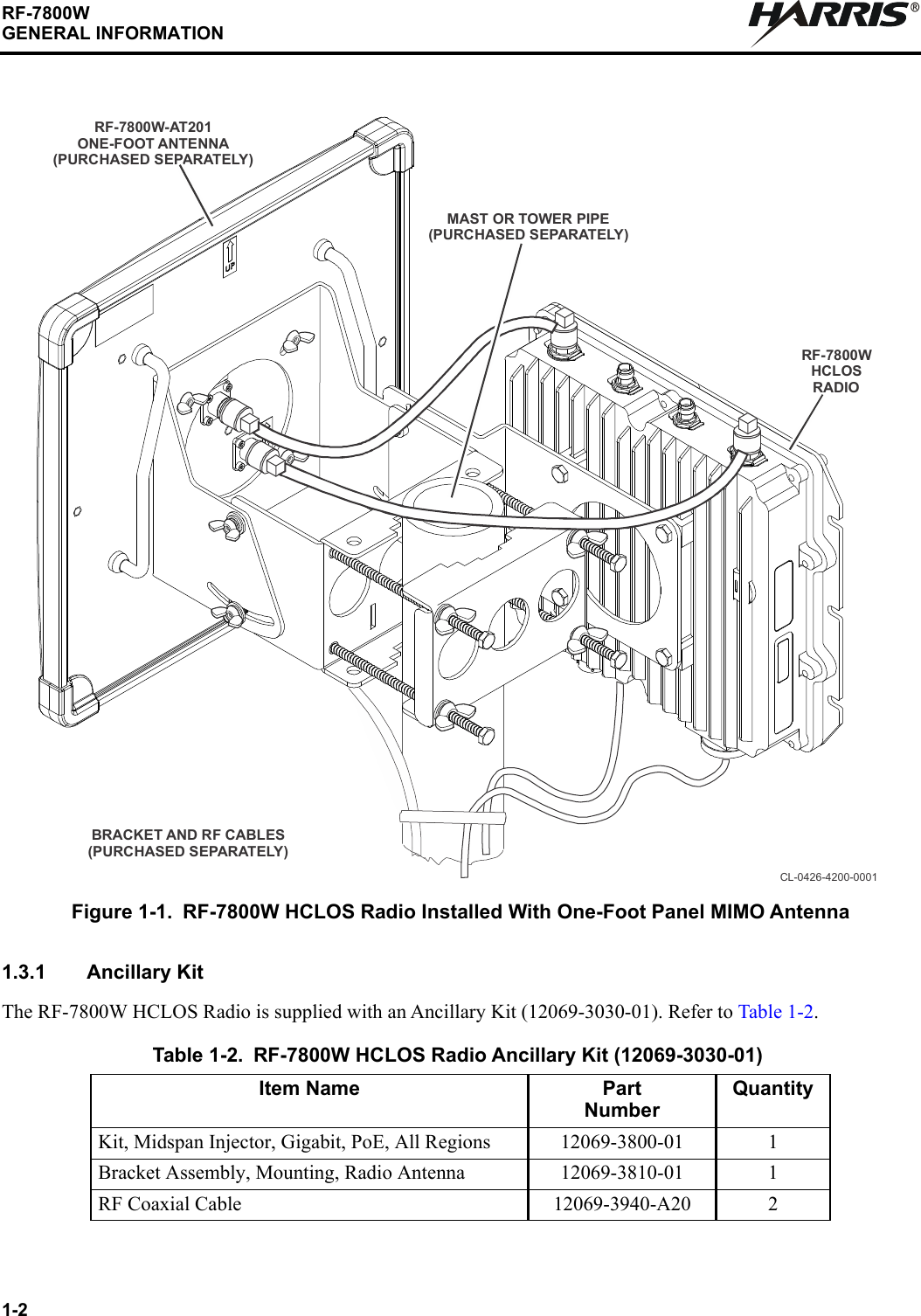
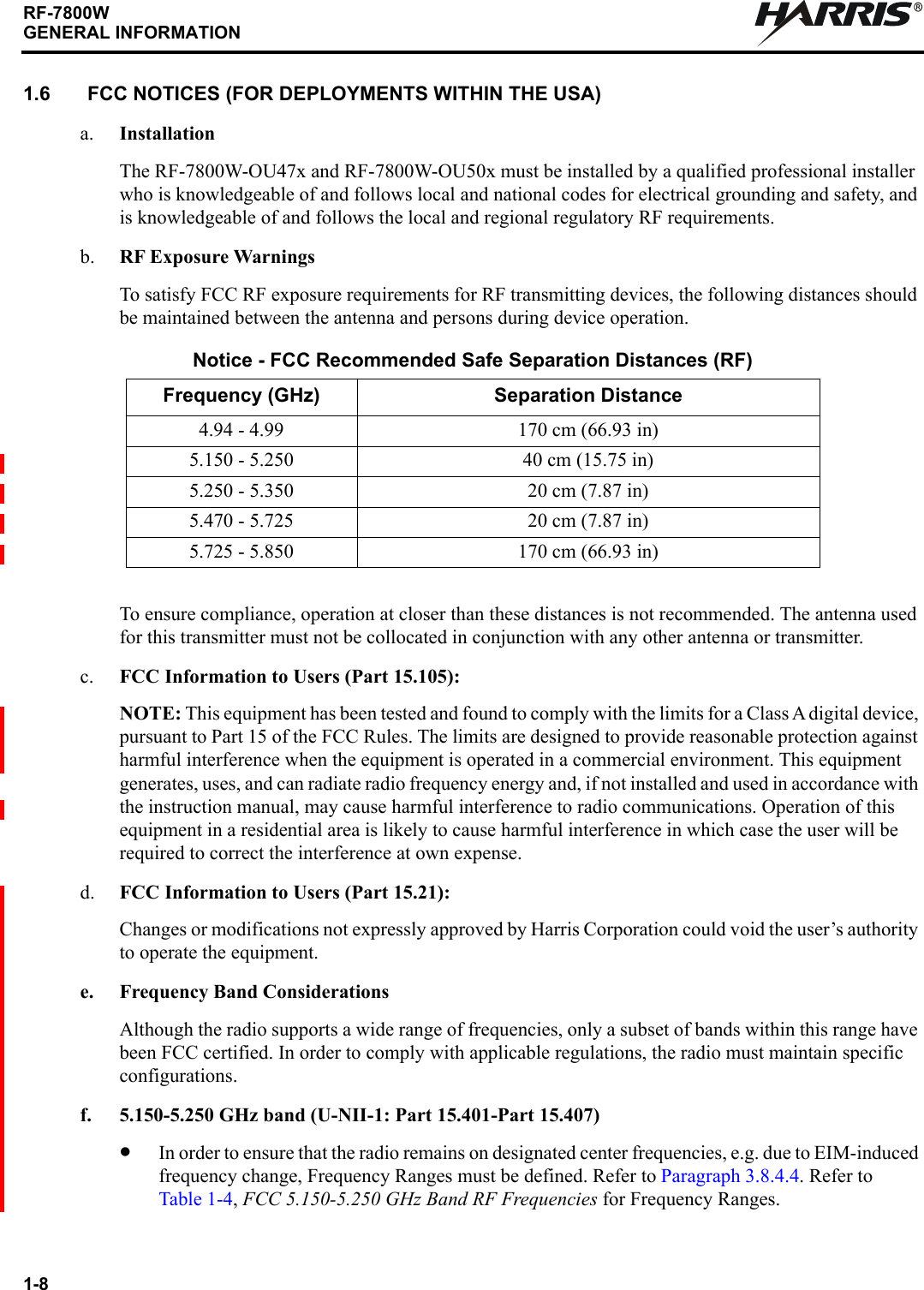
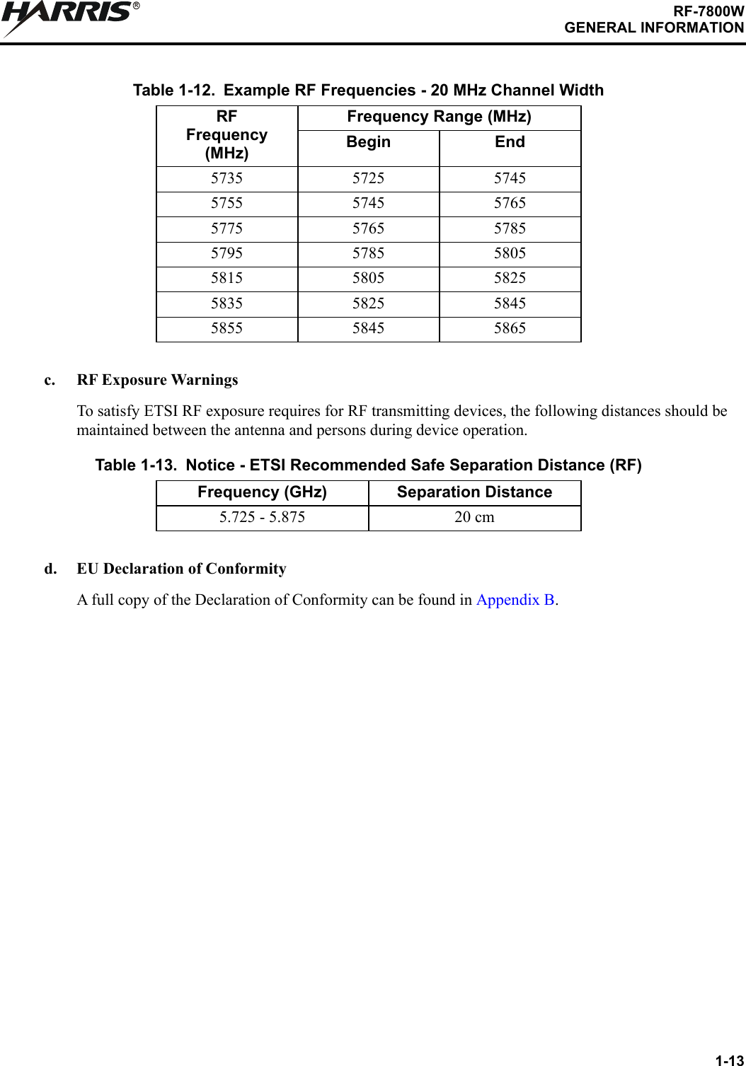
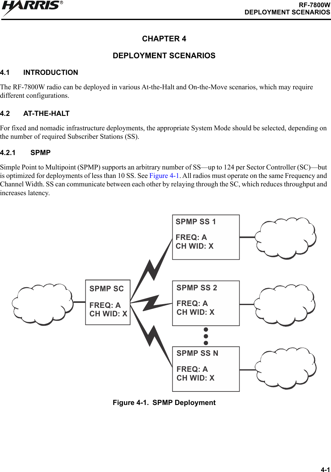
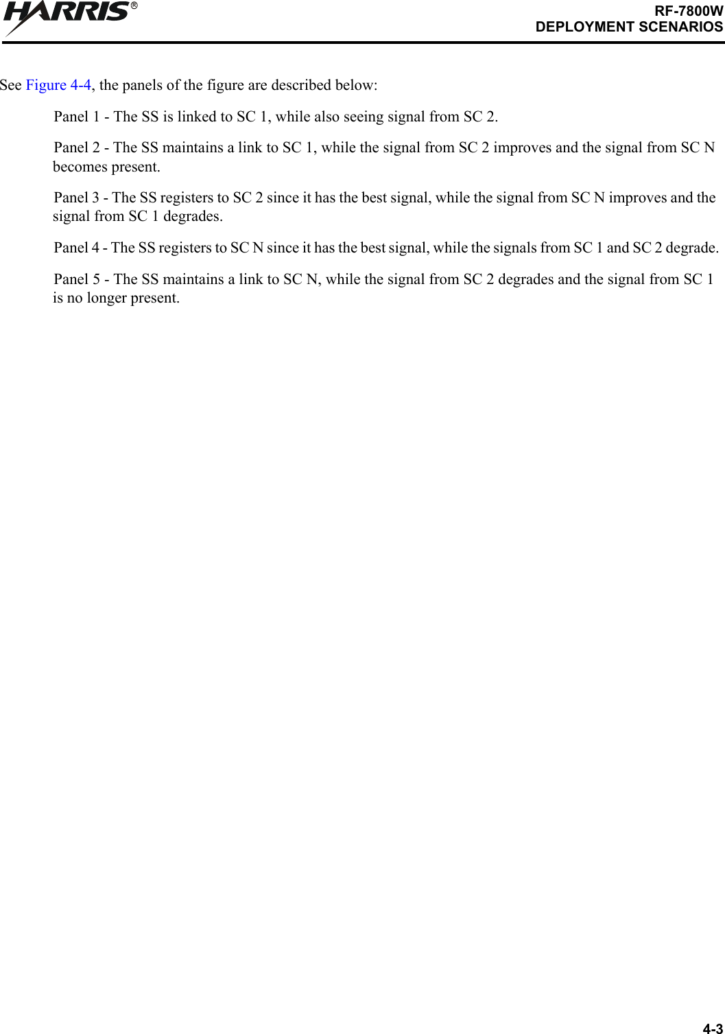
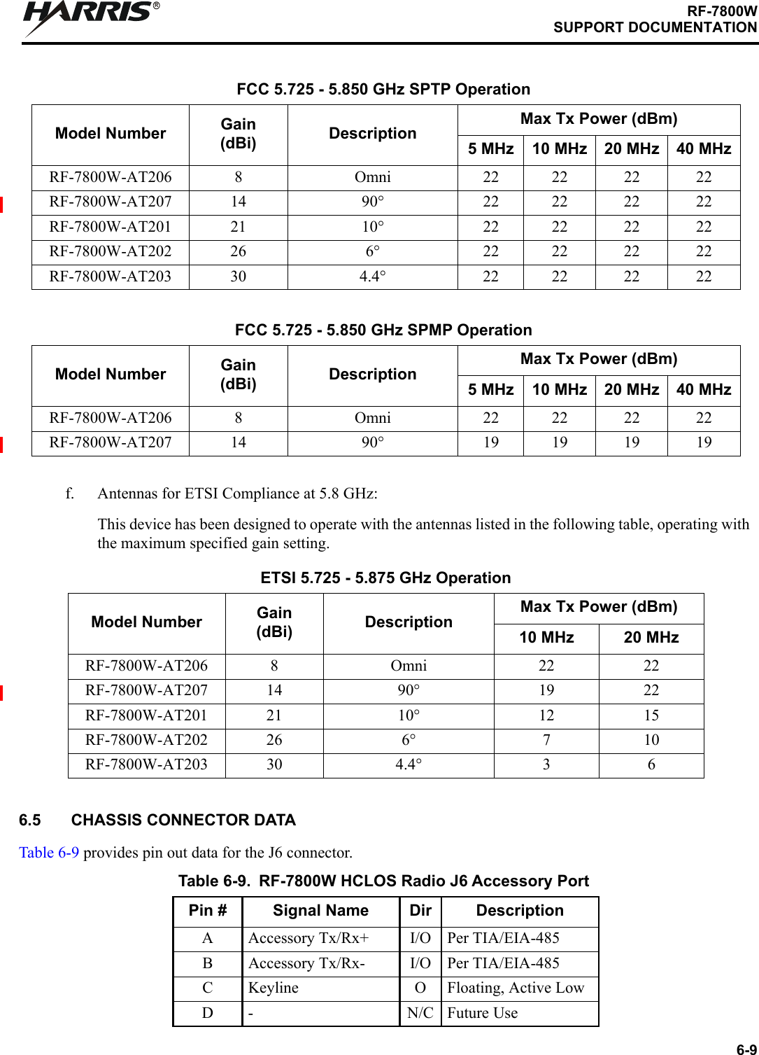
 20 MHz: 5725+(n*2.5) MHz [where n = 4 to 56]•In order to ensure that the radio remains on designated center frequencies, e.g. due to a DFS-induced frequency change, Frequency Ranges must be defined. Refer to Paragraph 3.8.4.4. Refer to Table 1-11 and Table 1-12 for example non-overlapping Frequency Ranges.•The Tx Power must be reduced in order to achieve Equivalent Isotropically Radiated Power (EIRP) limits. Refer to Paragraph 6.4.Table 1-11. Example RF Frequencies - 10 MHz Channel WidthRFFrequency(MHz)Frequency Range (MHz)Begin End5730 5725 57355740 5735 57455750 5745 57555760 5755 57655770 5765 57755780 5775 57855790 5785 57955800 5795 58055810 5805 58155820 5815 58255830 5825 58355840 5835 58455850 5845 58555860 5855 58655870 5865 5875](https://usermanual.wiki/Harris-RF-Communications-Division/RF-7800W-G2.Revised-User-Manual-Draft/User-Guide-3982570-Page-27.png)

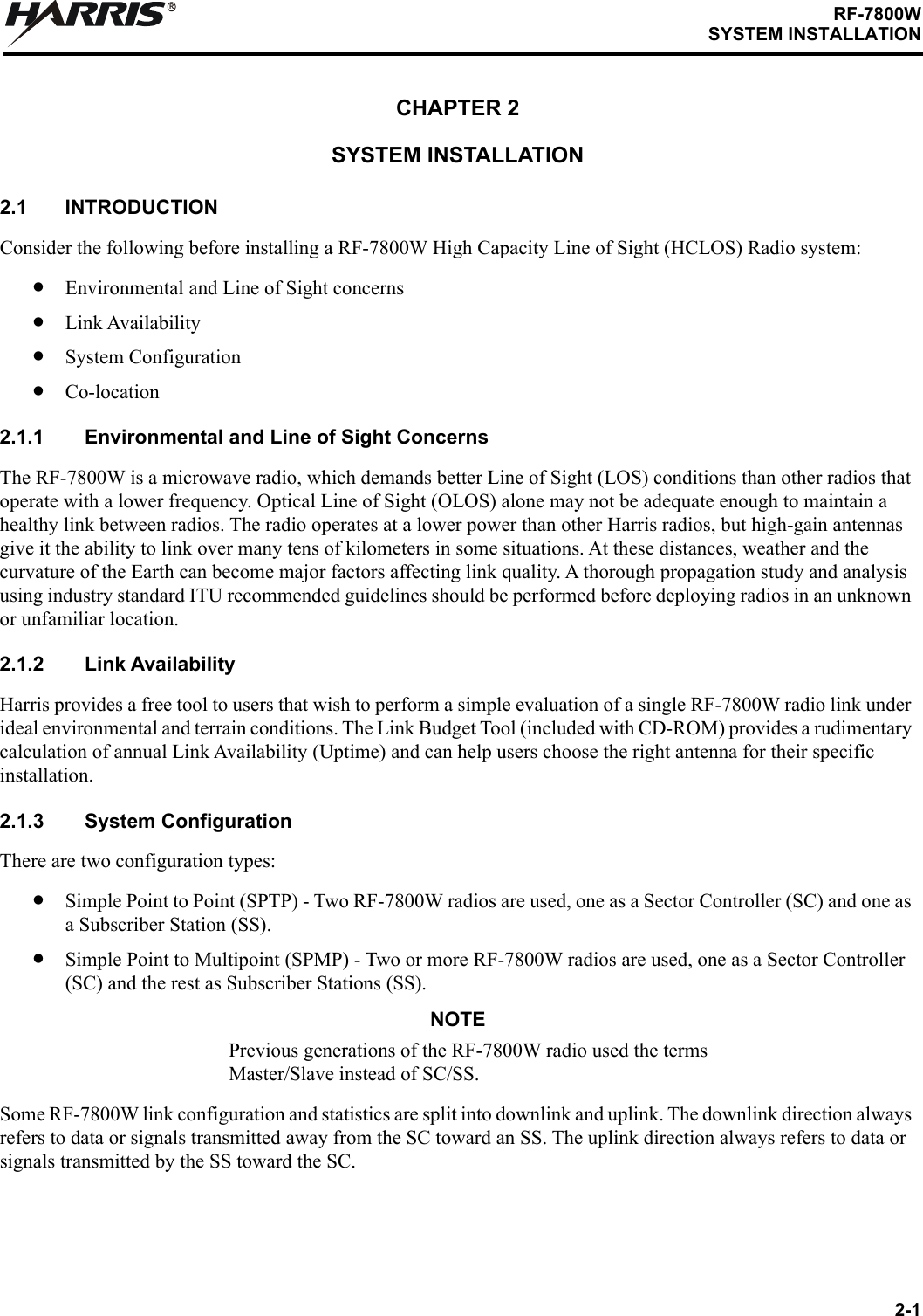

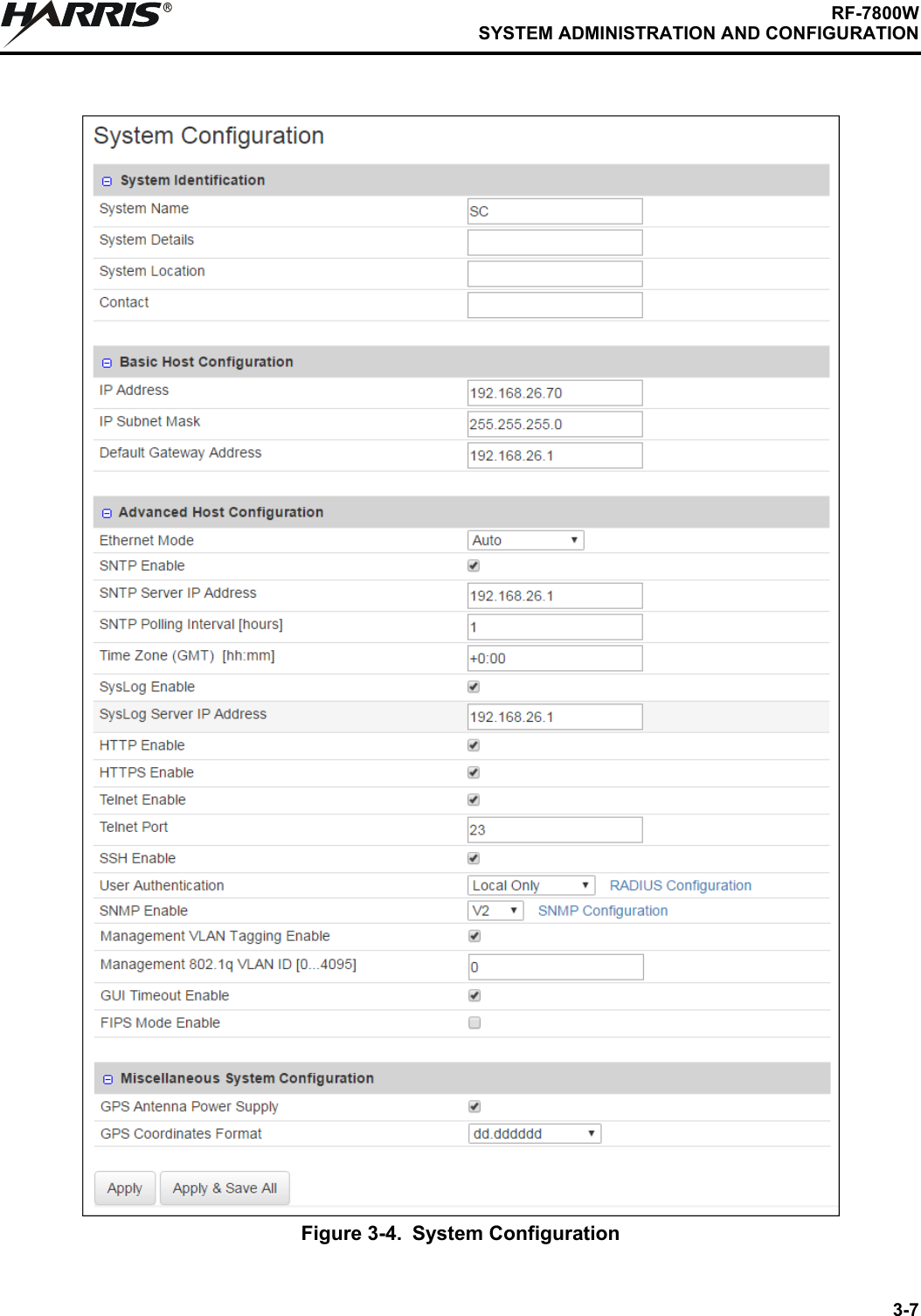
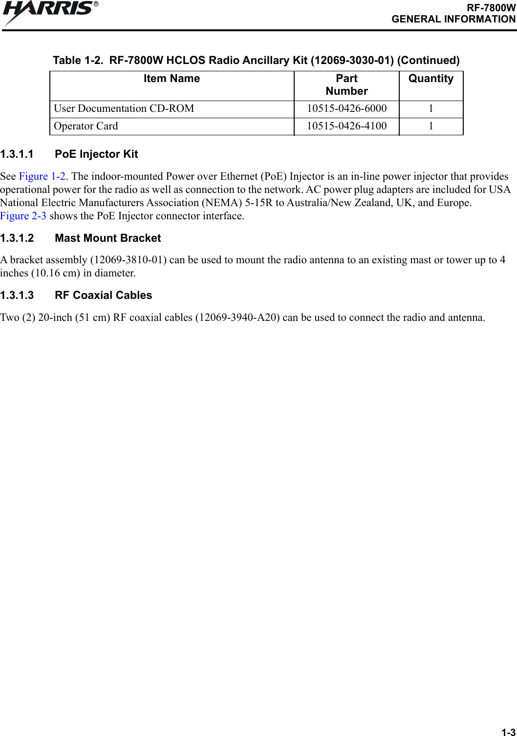
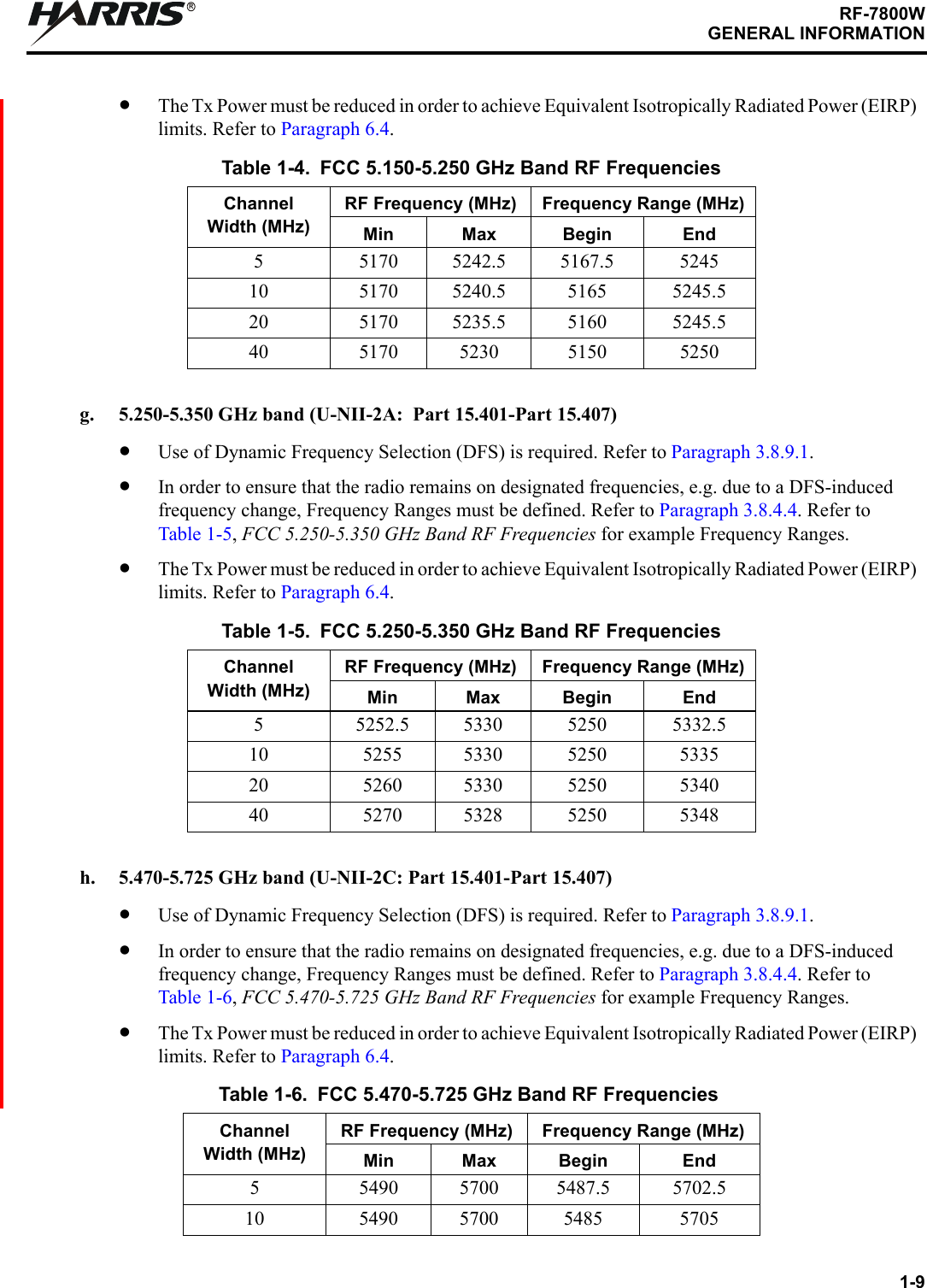
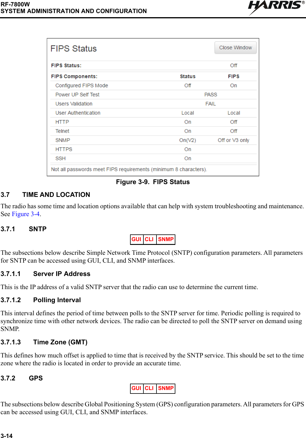
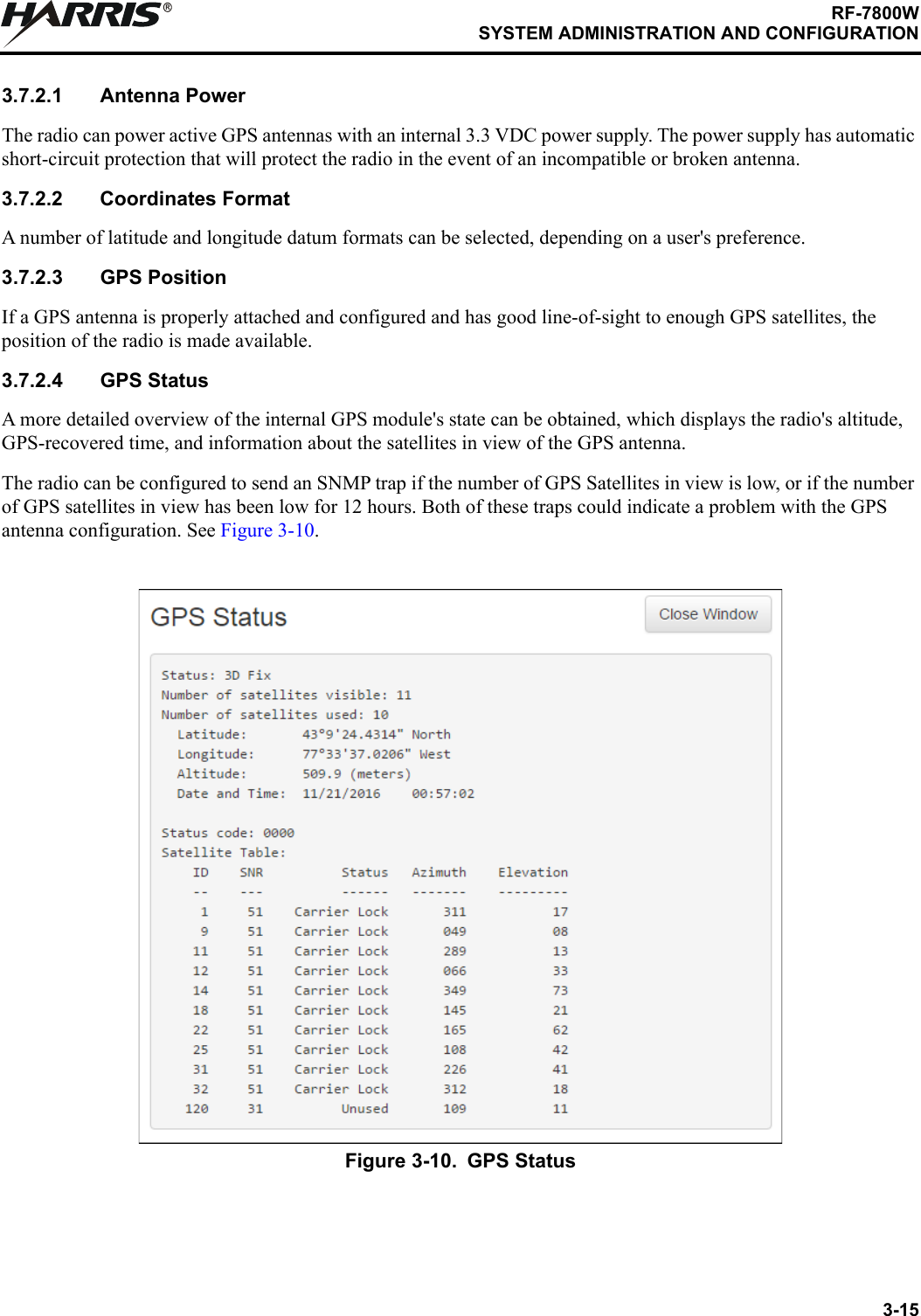
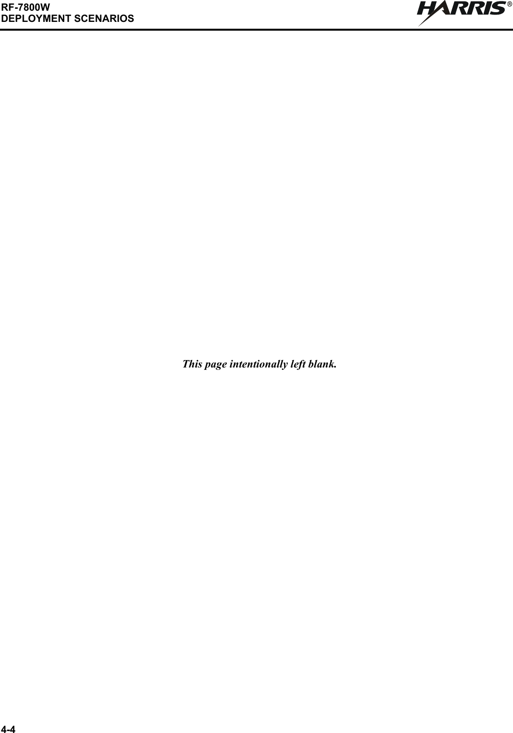
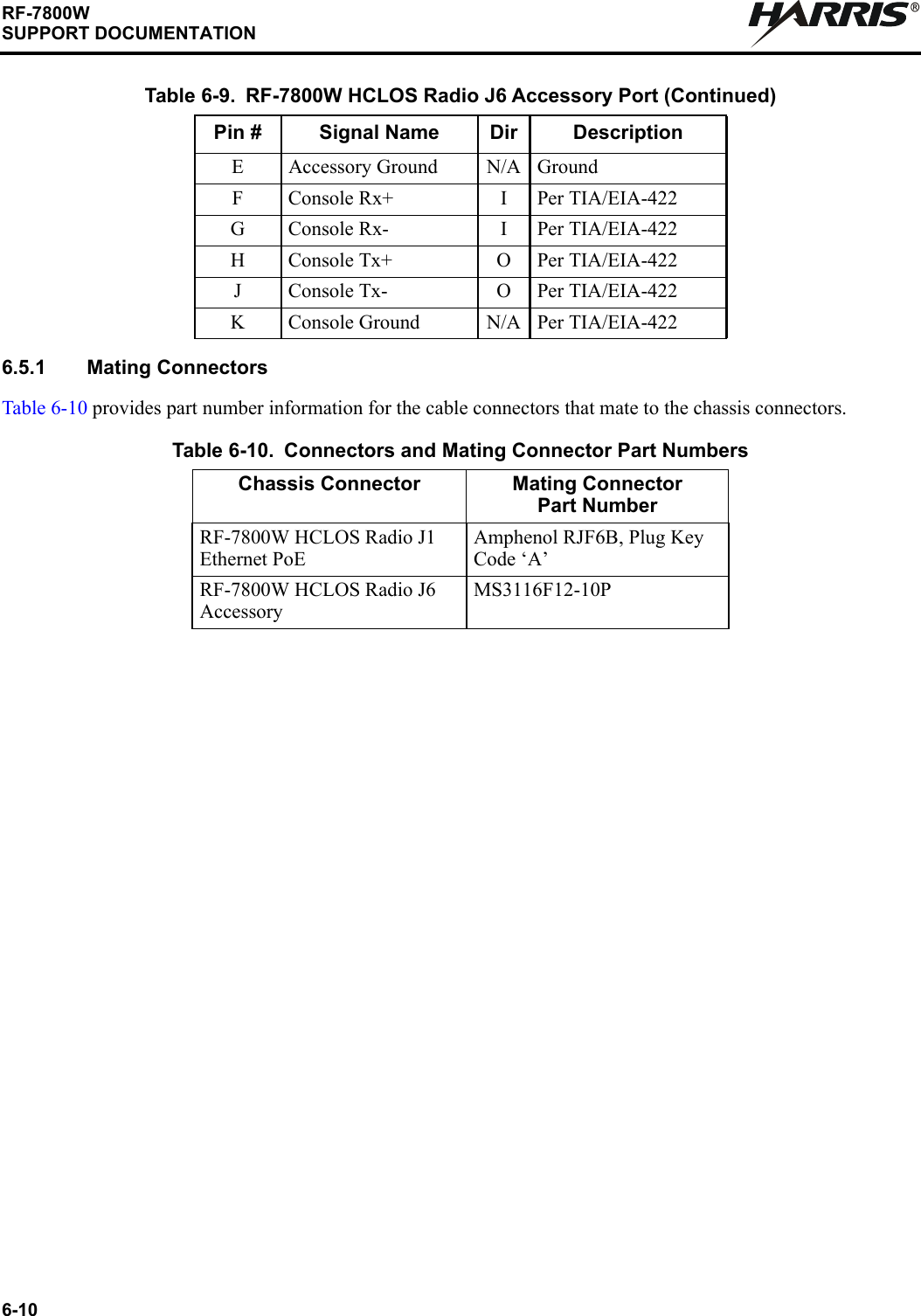
![3-11RF-7800WSYSTEM ADMINISTRATION AND CONFIGURATIONR3.6.4 SNMPThe subsections below describe SNMP Management Interfaces configuration parameters. Click on the blue [SNMP Configuration] link shown in Figure 3-4 to access the screen. See Figure 3-7.3.6.4.1 SNMP VersionsSNMP v2c and SNMP v3 are the supported network management versions. Only one version can be active at a time.3.6.4.2 CommunitiesCommunity configuration is required for SNMP v2c only. The communities are simple passwords for an SNMP polling agent that control whether the agent can perform read, write, or both types of operations on SNMP objects in the radio. The default communities are “public” and “private” with read-only and read-write operations permitted, respectively.3.6.4.3 TrapsSNMP traps are notifications that are sent to pre-defined destinations when certain events occur. These event notifications are useful in large, heavily managed network infrastructures because they simplify the network manager's monitoring responsibilities. Depending on the network management tool used, traps can initiate high-priority e-mails or SMS text messages to a network administrator that can be used to quickly diagnose a problem with the network.GUI CLIGUI CLIGUI CLI SNMP](https://usermanual.wiki/Harris-RF-Communications-Division/RF-7800W-G2.Revised-User-Manual-Draft/User-Guide-3982570-Page-50.png)
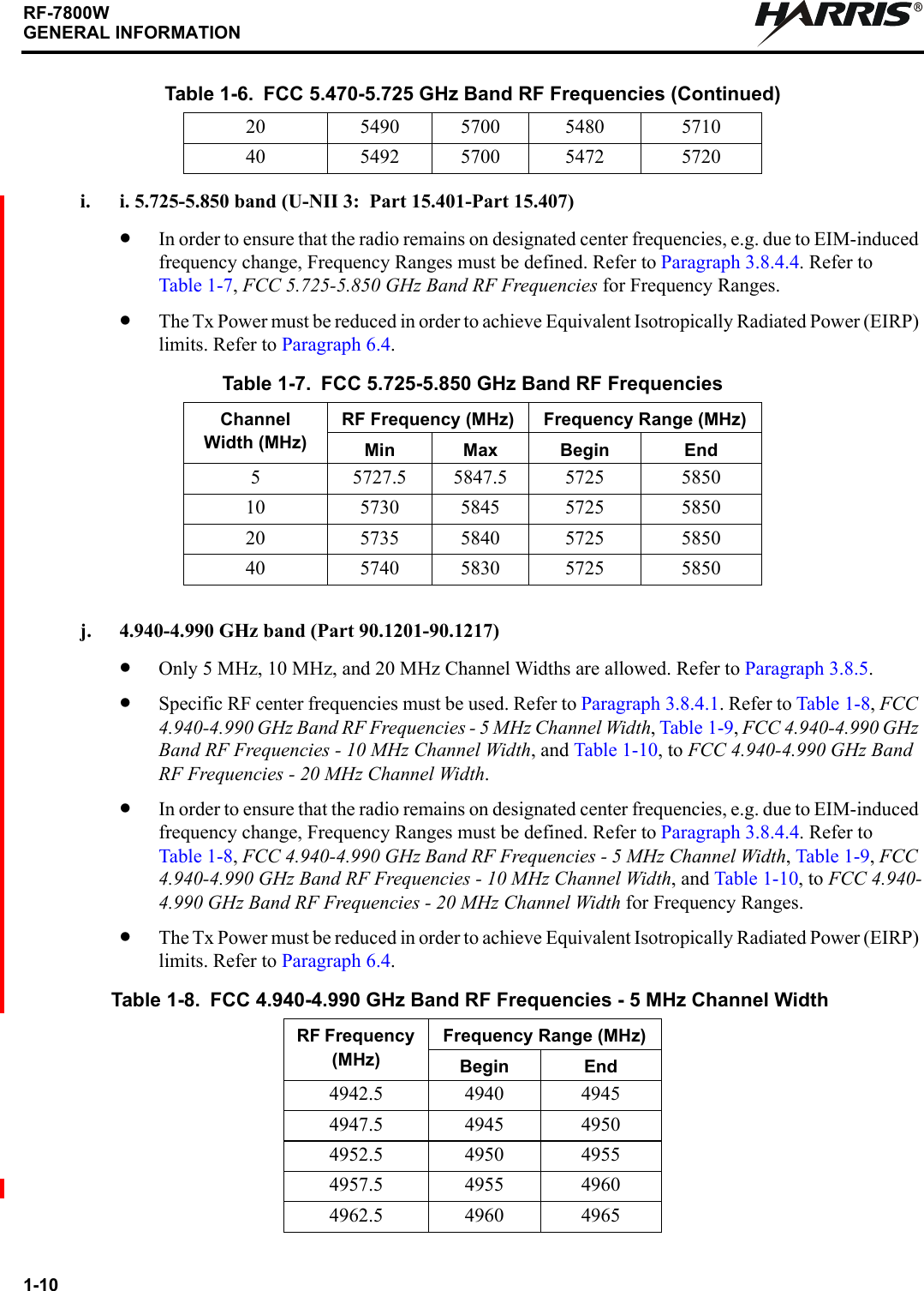
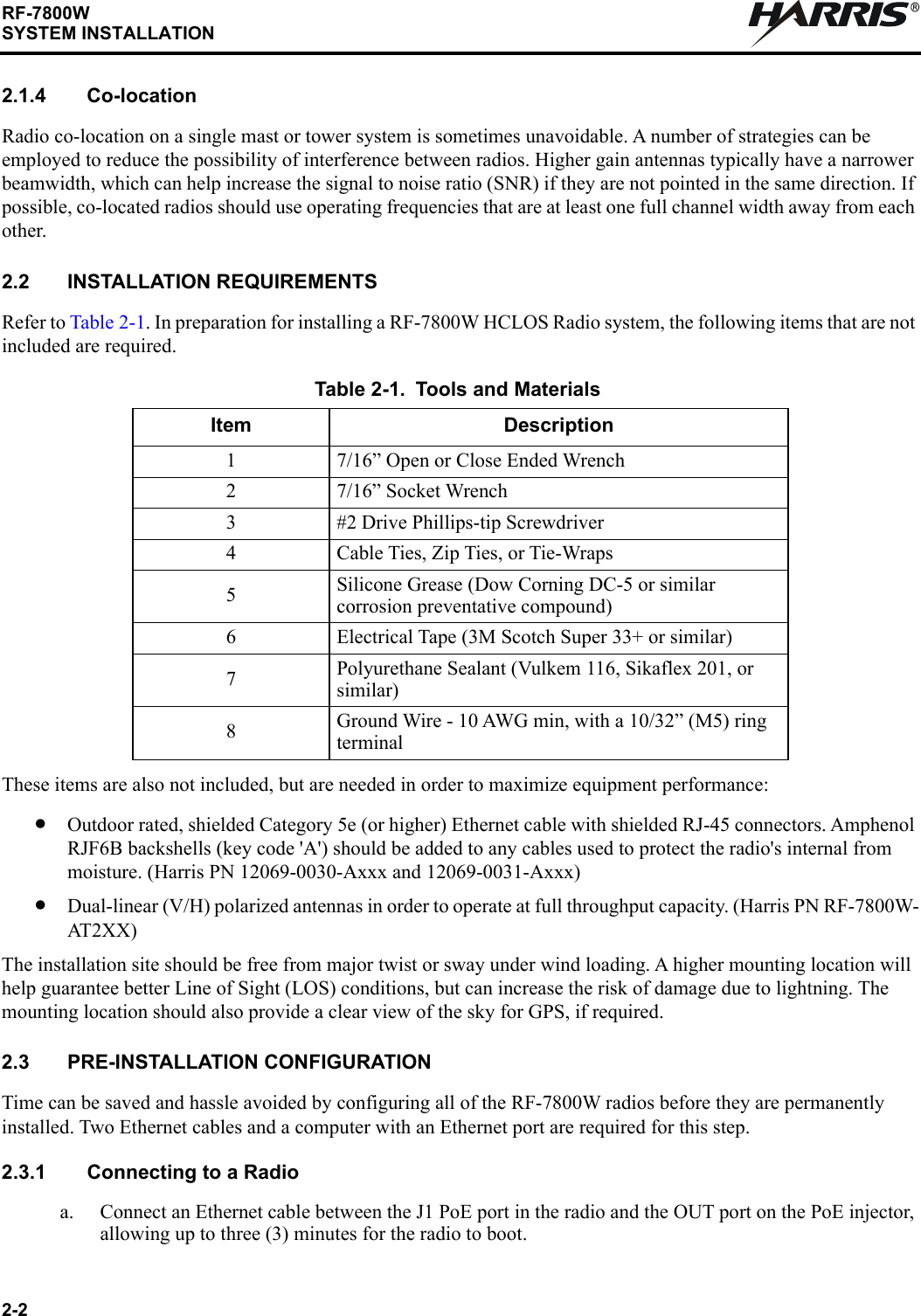
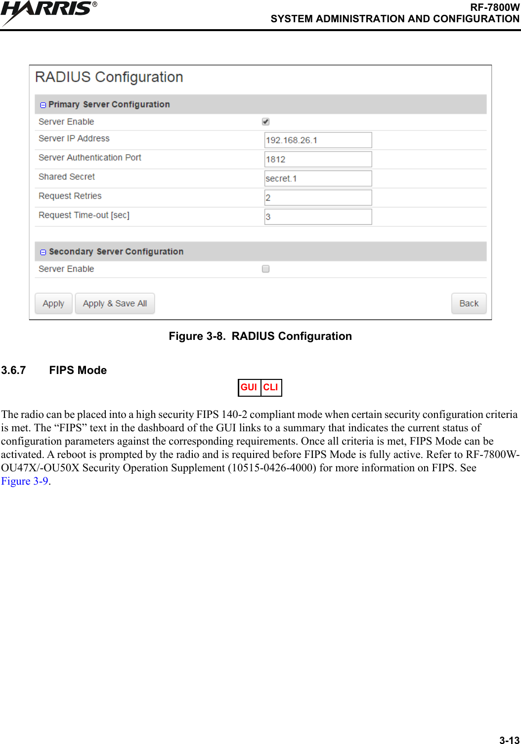
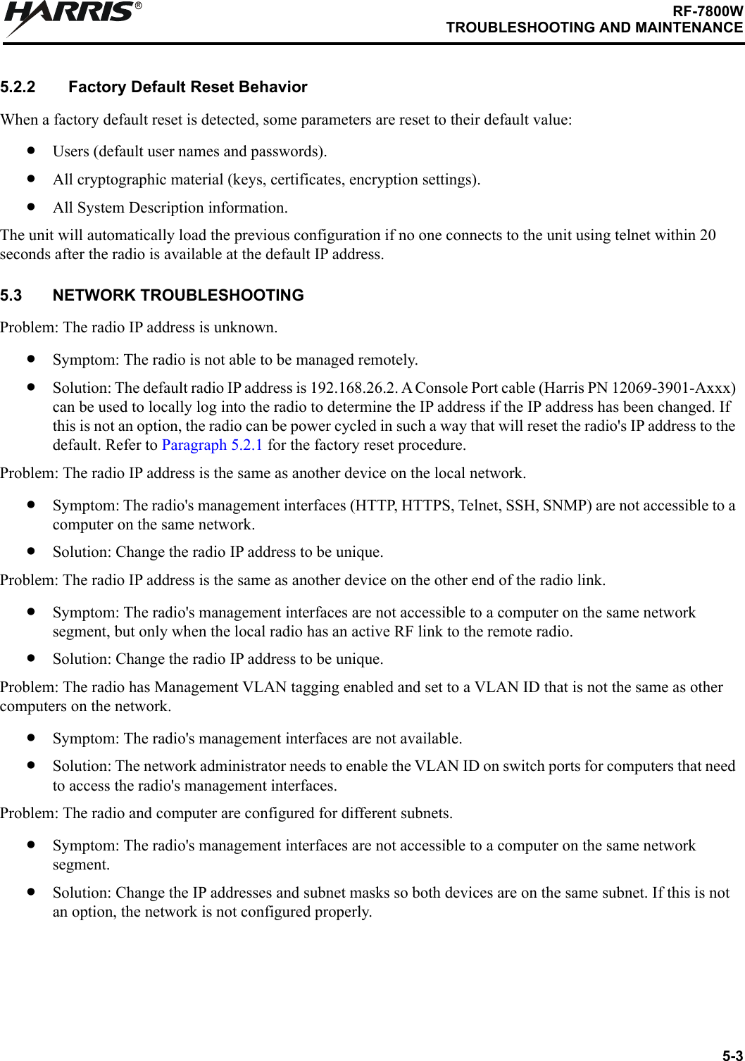
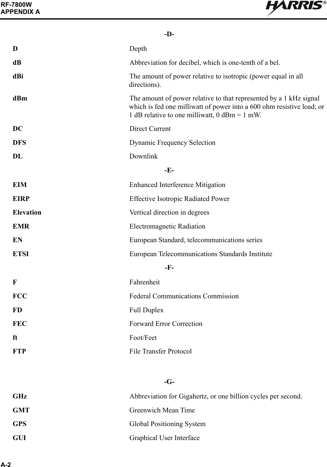
![3-12RF-7800WSYSTEM ADMINISTRATION AND CONFIGURATIONR3.6.5 AccessThe interface for radio management traffic and over-the-link traffic is shared on the Ethernet port. In certain situations, it may be desirable to separate the management traffic from the over-the-link traffic. This can be done within the radio by tagging management traffic with a specific 802.1Q Virtual Local Area Network (VLAN) Identification (ID).3.6.6 Remote Users (User-Based Authentication)The subsections below describe RADIUS Management Interfaces configuration parameters. Click on the blue [RADIUS Configuration] link shown in Figure 3-4 to access the screen. See Figure 3-8.3.6.6.1 RADIUSRADIUS support ties the radio's user-authentication system into an existing enterprise system to enable existing user names and passwords to be used to log into the radio. It can be configured to work with the radio's user-authentication system, or as a replacement for it.Figure 3-7. SNMP Configuration GUI CLIGUI CLI](https://usermanual.wiki/Harris-RF-Communications-Division/RF-7800W-G2.Revised-User-Manual-Draft/User-Guide-3982570-Page-51.png)
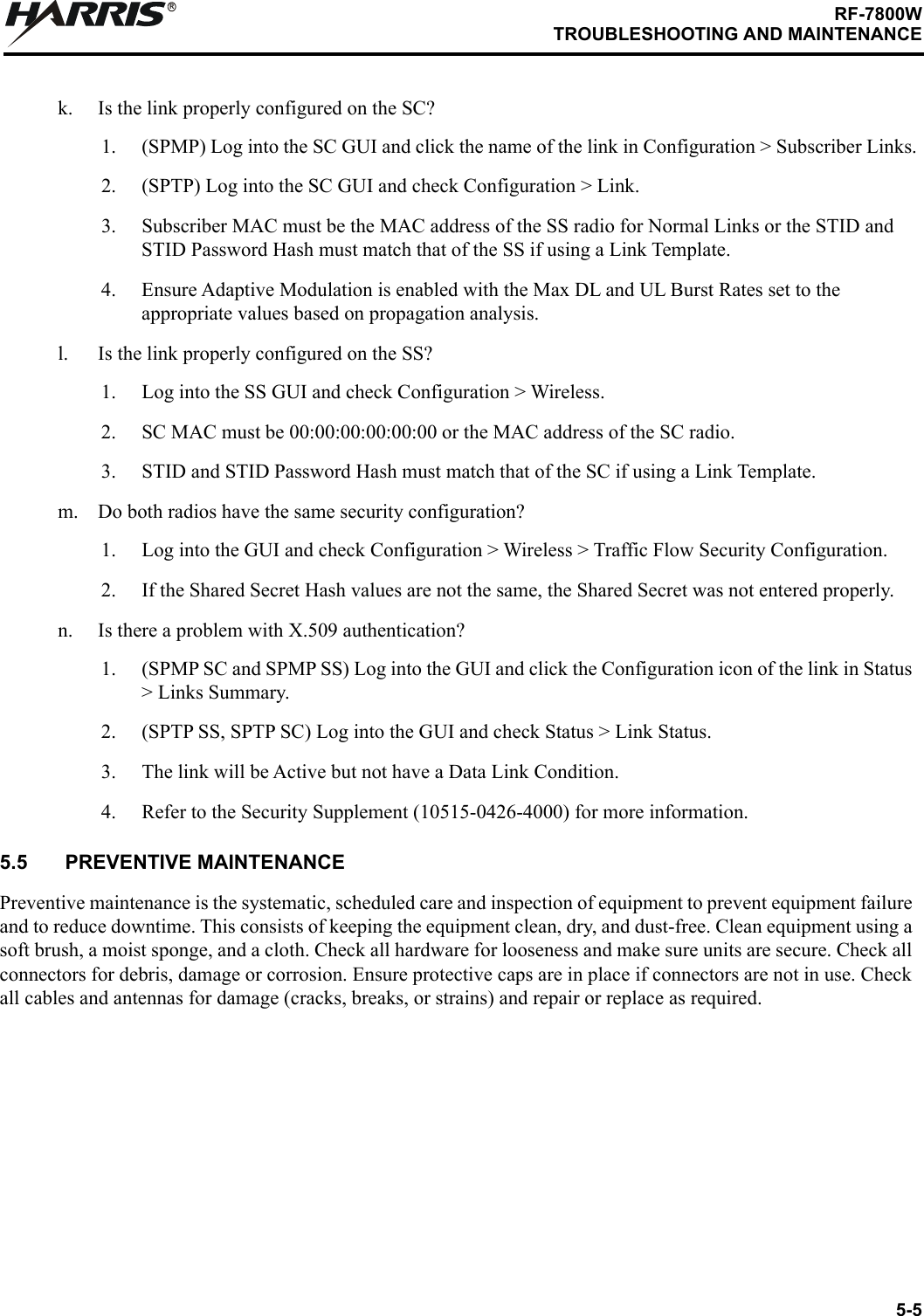
![5-1RF-7800WTROUBLESHOOTING AND MAINTENANCERCHAPTER 5TROUBLESHOOTING AND MAINTENANCE5.1 INTRODUCTIONThis chapter provides troubleshooting data necessary for fault isolation and preventive maintenance guidelines.5.1.1 Scope of this Chapter The procedures presented in this chapter assume that a Level I fault has led the user to suspect a fault with the RF-7800W HCLOS Radio. The user begins the troubleshooting process with the Factory Reset procedure.The maintainer will use the status code/system log troubleshooting procedures if there is a fault as a result of a status code or system log. The maintainer will use the non-BIT troubleshooting procedure if there is a non-Built-in Test (BIT) fault. The radio system is returned to operational readiness once the problem is found and corrected.5.2 TROUBLESHOOTING PROCEDURESTroubleshooting starts with the factory reset procedure described below. NOTEFactory defaults can be restored using either the Command Line interface (CLI) command of save defaultconfig [Enter] or Factory Defaults utility in the Navigation menu (left side pane) of the GUI.5.2.1 Factory Reset ProcedureSee Figure 5-1. It may be necessary to reset to the factory IP address (e.g. due to lost admin user name and password). This can be accomplished by having local access to the Power over Ethernet (PoE) Injector, the ability to power-cycle the RF-7800W HCLOS Radio, a PC with a Telnet client, and an Ethernet cable. Perform the following procedure to reset the factory default IP address:a. Connect a PC to the input connector of a PoE Injector using an Ethernet cable.b. Connect the RF-7800W HCLOS Radio to the output connector of the PoE supply using an Ethernet cable and leave the radio powered on for a few minutes. c. Open a command prompt window on the PC and type telnet 192.168.26.2 without pressing [Enter]. d. Open a second command prompt window, type ping 192.168.26.2 -t, and press [Enter].e. Remove power from the radio for approximately six to eight seconds by disconnecting the Ethernet cable from the Output connector of the PoE Injector and then reconnecting.f. Observe that pings return from 192.168.26.2 (approximately 2 minutes 40 seconds).g. Press [Enter] in the Telnet window on the PC. h. Observe the Login prompt, and if you do not see the Login prompt, repeat the command telnet 192.168.26.2 and press [Enter] until you see the prompt.](https://usermanual.wiki/Harris-RF-Communications-Division/RF-7800W-G2.Revised-User-Manual-Draft/User-Guide-3982570-Page-90.png)
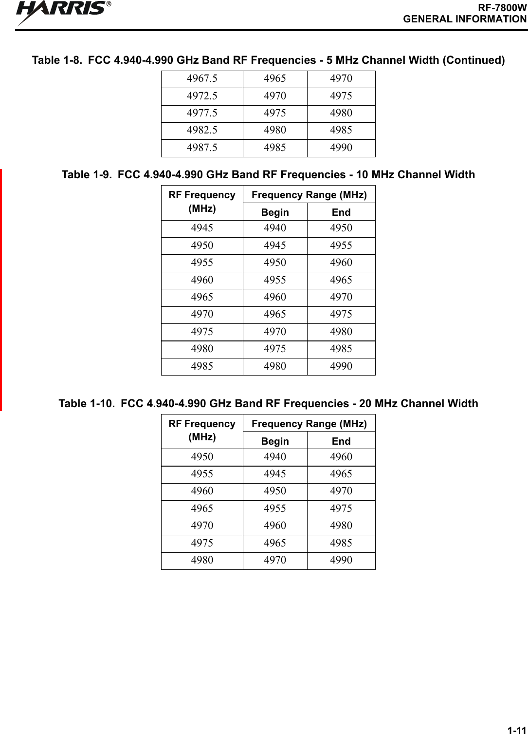
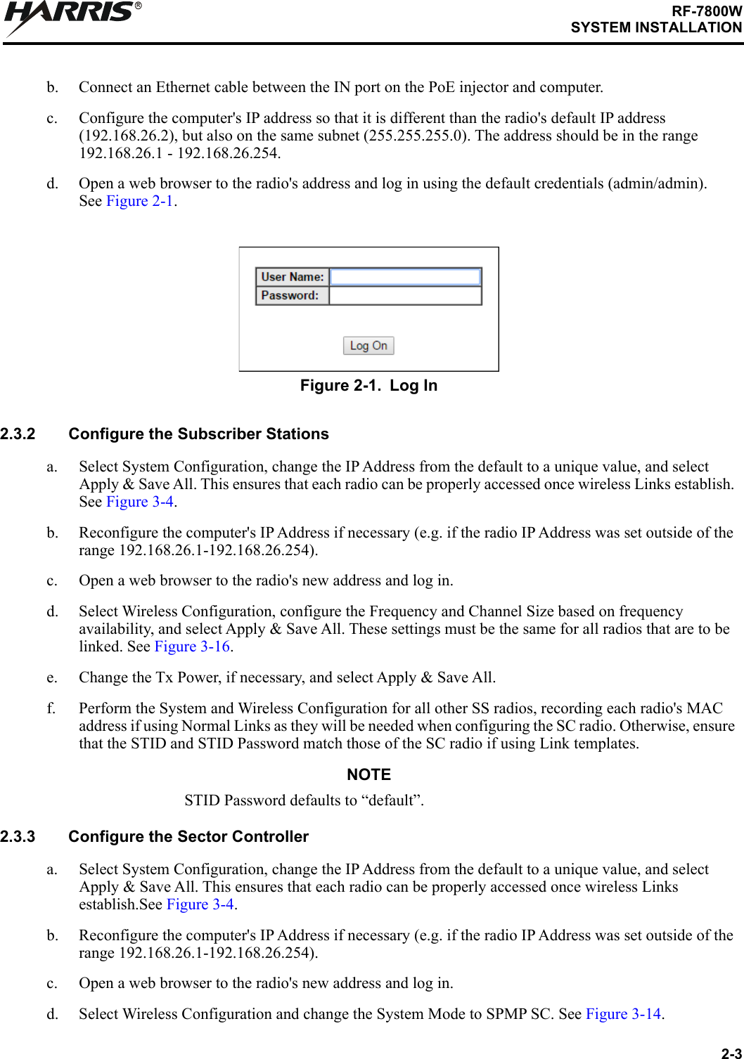
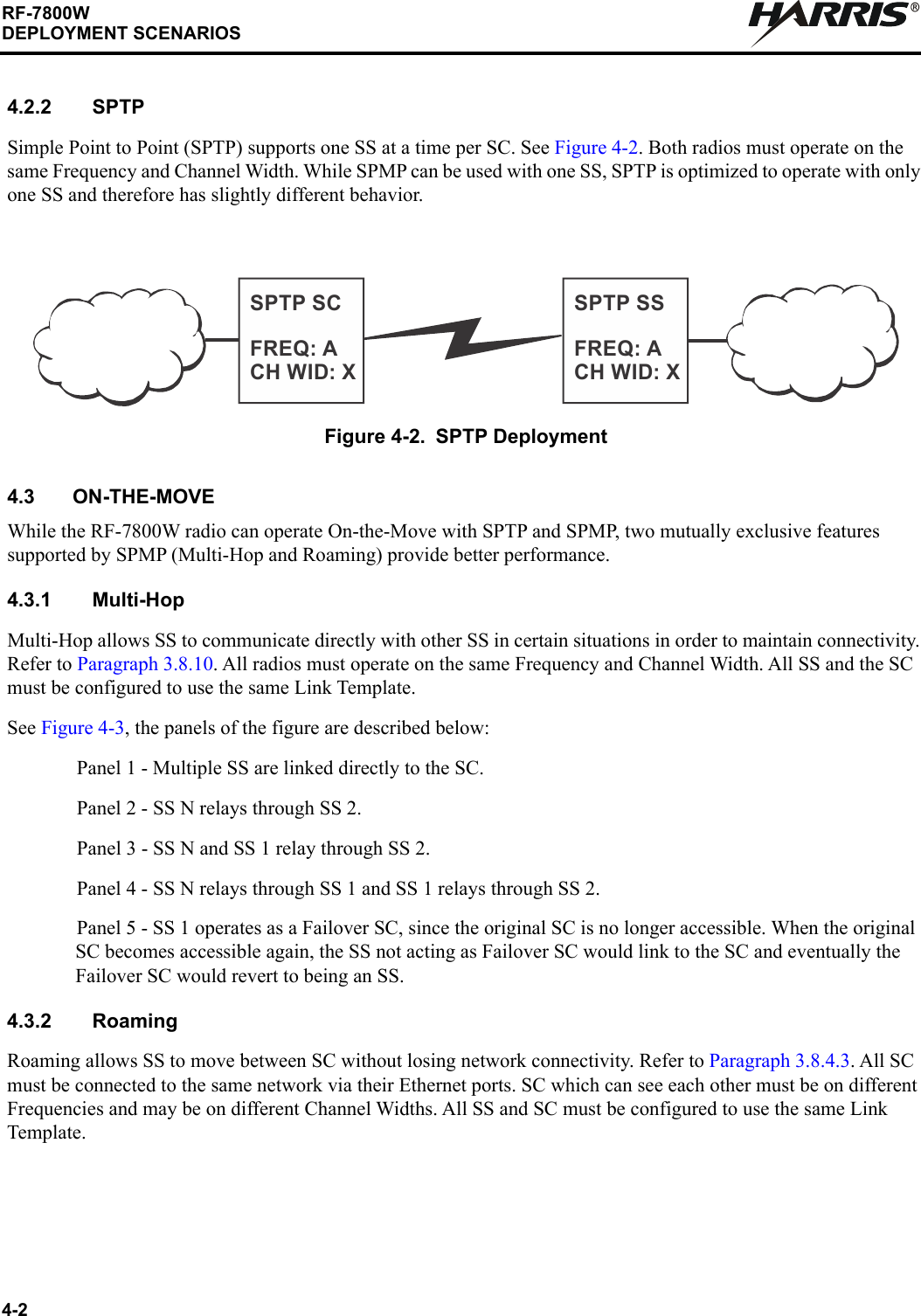
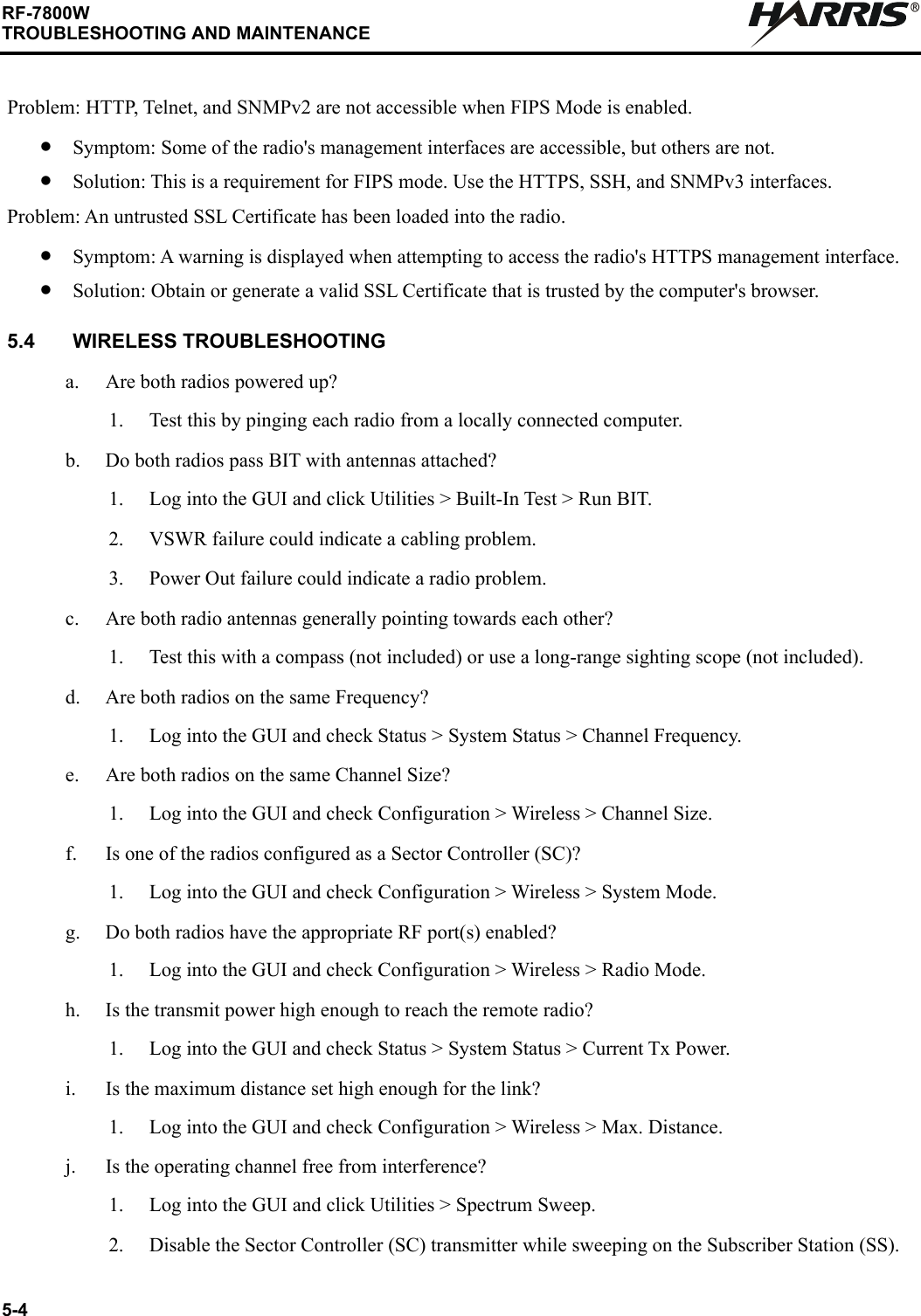
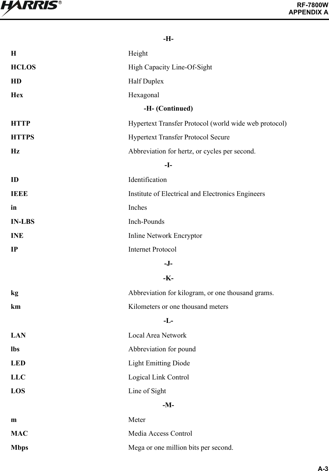
![5-2RF-7800WTROUBLESHOOTING AND MAINTENANCERNOTEThe Telnet session must connect to the RF-7800W HCLOS Radio within approximately 20 seconds from when the radio starts responding to pings. Logging into the default IP Address will cause the unit to be reset to the factory default configuration.i. Enter the following to log in:1. User Name - type admin and press [Enter].2. Password - type admin and press [Enter]. The password characters do not echo to the computer screen.j. Enter the command save defaultconfig and press [Enter] to ensure that all parameters are set to default values.k. Enter the following commands to set a new IP address. A 192.168.26.2# prompt is shown at each step.1. set ipaddr <IP Address> followed by [Enter]. Note the spaces in this example: set ipaddr 192.168.100.12. save config followed by [Enter]. A message such as, “Connection to host lost.” will display.l. Log in to the new IP address and use the user command to enter new user name and password information, if required.Figure 5-1. Factory Default Reset Time FrameCL-0426-4200-0020POWER OFF 6 TO 8 SECONDSPOWER ON GREATER THAN3 MINUTESPOWER ON APPROX. 2 MINUTES 40 SECONDSAND BEGIN TELNET SESSION](https://usermanual.wiki/Harris-RF-Communications-Division/RF-7800W-G2.Revised-User-Manual-Draft/User-Guide-3982570-Page-91.png)
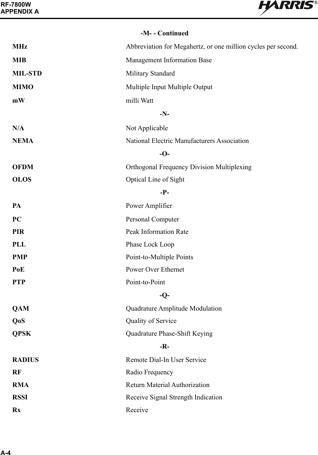
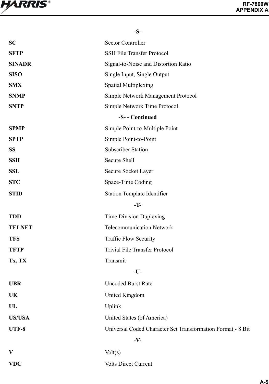
![A-1RF-7800WAPPENDIX ARAPPENDIX AGLOSSARYA.1 GLOSSARYThe following provides a glossary of terms used in this manual.-A-AC Alternating CurrentAdmin AdministratorAES Advanced Encryption StandardARP Address Resolution ProtocolATPC Automatic Transmit Power ControlAzimuth Horizontal direction containing bearing from Global Positioning System [GPS] or compass-B-bit A binary digit that can have a value of 0 or 1.BIT Built-in TestBPSK Binary Phase Shift Keying-C-CCelsiusCA Certification AuthorityCAGE Commercial and Government EntityCat5e Category 5e, Used in reference to Ethernet cabling that conforms to Cat5e specification.CD-ROM Compact Disk-Read-Only MemoryCE Conformité Européene (European Conformity)CIR Committed Information RateCLI Command Line Interfacecm CentimeterCN Common Nameconfig Configuration](https://usermanual.wiki/Harris-RF-Communications-Division/RF-7800W-G2.Revised-User-Manual-Draft/User-Guide-3982570-Page-104.png)

![TECHNICAL PUBLICATIONEVALUATION FORMTo the User of this Instruction Manual:HARRIS Corporation, continually evaluates its technical publications for completeness, technical accuracy, and organization. You can assist in this process by completing and returning this form. Please specify section, page number, figure or table number where applicable.MANUAL TITLE:MANUAL NUMBER: REVISION: COVER DATE:GENERAL EXCELLENT GOOD FAIR POORTEXT [ ] [ ] [ ] [ ]SETUP/ALIGNMENT INST. [ ] [ ] [ ] [ ]TROUBLESHOOTING INST. [ ] [ ] [ ] [ ]TABLES [ ] [ ] [ ] [ ]ILLUSTRATIONS [ ] [ ] [ ] [ ]PARTS LISTS [ ] [ ] [ ] [ ]SCHEMATIC DIAGRAMS [ ] [ ] [ ] [ ]GENERAL COMMENTS: Please include your suggestions for improvements to the manual. Specify chapter, page, paragraph, figure number, or table number as applicable. Attach examples or extra pages if more space is needed.CHAPTER EXCELLENT GOOD FAIR POORINTRODUCTION/GENERAL INFORMATION [ ] [ ] [ ] [ ]OPERATION [ ] [ ] [ ] [ ]FUNCTIONAL DESC/THEORY OF OPERATION [ ] [ ] [ ] [ ]SCHEDULED MAINTENANCE [ ] [ ] [ ] [ ]TROUBLESHOOTING [ ] [ ] [ ] [ ]CORRECTIVE MAINTENANCE [ ] [ ] [ ] [ ]DOCUMENTATION [ ] [ ] [ ] [ ]INSTALLATION [ ] [ ] [ ] [ ]ACCESSORIES [ ] [ ] [ ] [ ]CUT HERE LEAF-043A MAP](https://usermanual.wiki/Harris-RF-Communications-Division/RF-7800W-G2.Revised-User-Manual-Draft/User-Guide-3982570-Page-112.png)