Harris RF Communications Division VSR-4141-001 differential GPS ground station transmitter User Manual users manual
Harris Corporation RF Communications Division differential GPS ground station transmitter users manual
Contents
- 1. outline for exhibit
- 2. users manual
users manual
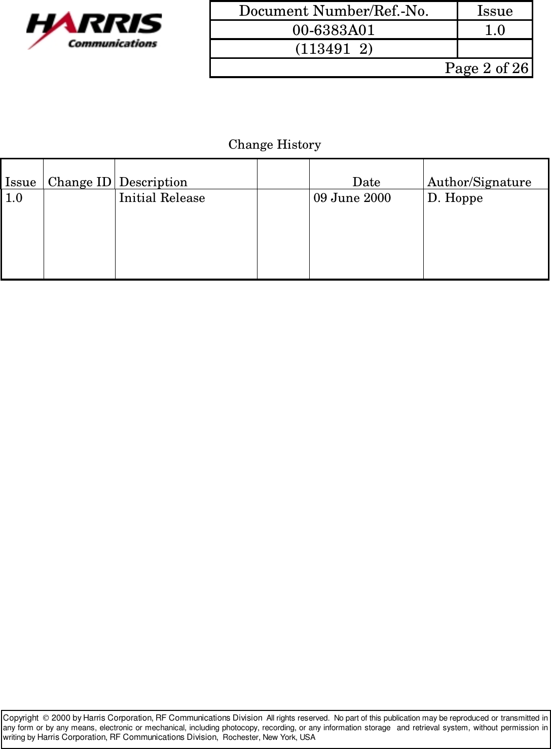
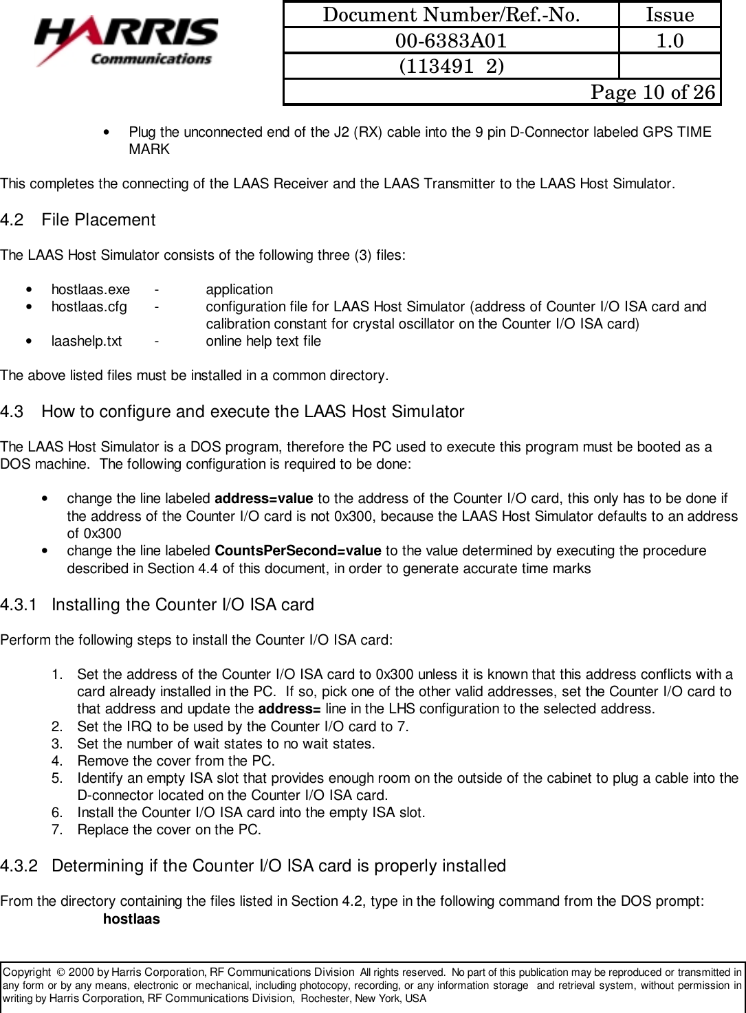

![Document Number/Ref.-No. Issue00-6383A01 1.0(113491 2) Page 15 of 26Copyright 2000 by Harris Corporation, RF Communications Division All rights reserved. No part of this publication may be reproduced or transmitted inany form or by any means, electronic or mechanical, including photocopy, recording, or any information storage and retrieval system, without permission inwriting by Harris Corporation, RF Communications Division, Rochester, New York, USAAppendix A – Help File Textbit [0/1] [r/t] [v/h] [s] [c]Requests the current BIT/Status from the receiver, transmitter, or both. With no argument requests BIT/Status from both the receiver and transmitter and displays the response in hex orverbose format. [0] disable automatic requests (nominally occur at 1 request per second) [1] enable automatic requests (nominally occur at 1 request per second) [r] command or option affects receiver only [t] command or option affects transmitter only [v] verbose (text description of response, 'sticky', i.e. applies to all subsequent requests until explicitly changed) [h] hex (response shown as hex characters, 'sticky') [s] suppress display of the BIT/Status response. Normally the response to the automatic request is displayed. This suppresses that display, this state is cleared by issuing a "bit v" or "bit h" command [c] send the BIT/Status Clear message to the transmitter or receiver (or both)--------------------txt q [s] b 1-249 [s] f file 0Commands the transmitter to start or stop a message transmission sequence. q [s] The message data transmitted is: "The quick brown fox jumped over the lazy dog 0123456789",0xD b 1-249 [s] The message data is the 511 BER data f file The message data is the 511 BER data, fil = filename of file containing transmission slots for Data Message and which slots to send the message from the LAAS Host Simulator to the transmitter 0 Stops a continuous transmission started by txt q, txt b, or txt f [s] Single Message Transmission (defaults to continuous)--------------------bfr 0, 6-222 [filename] d [0/1]Commands the transmitter to start or stop transmitting a message that contains 511 BER message data. Displays message transmission statistics. 0 Terminate Block Failure Rate test 6-222 The message data contains selected number of bytes of 511 BER message data](https://usermanual.wiki/Harris-RF-Communications-Division/VSR-4141-001.users-manual/User-Guide-113491-Page-15.png)
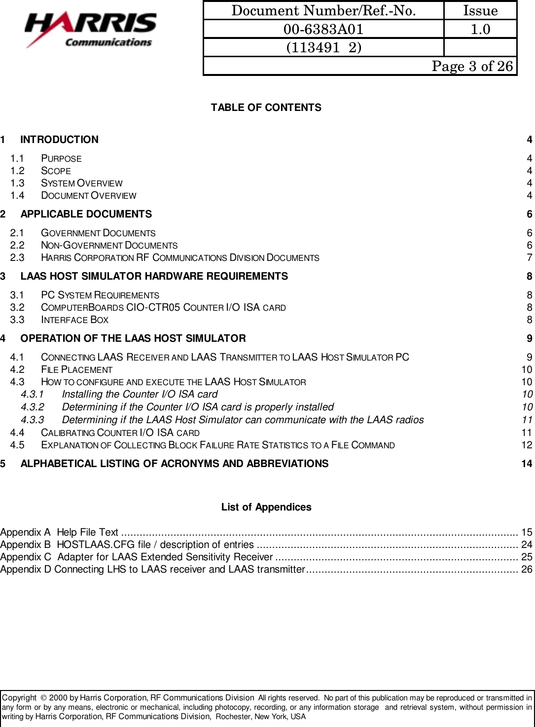
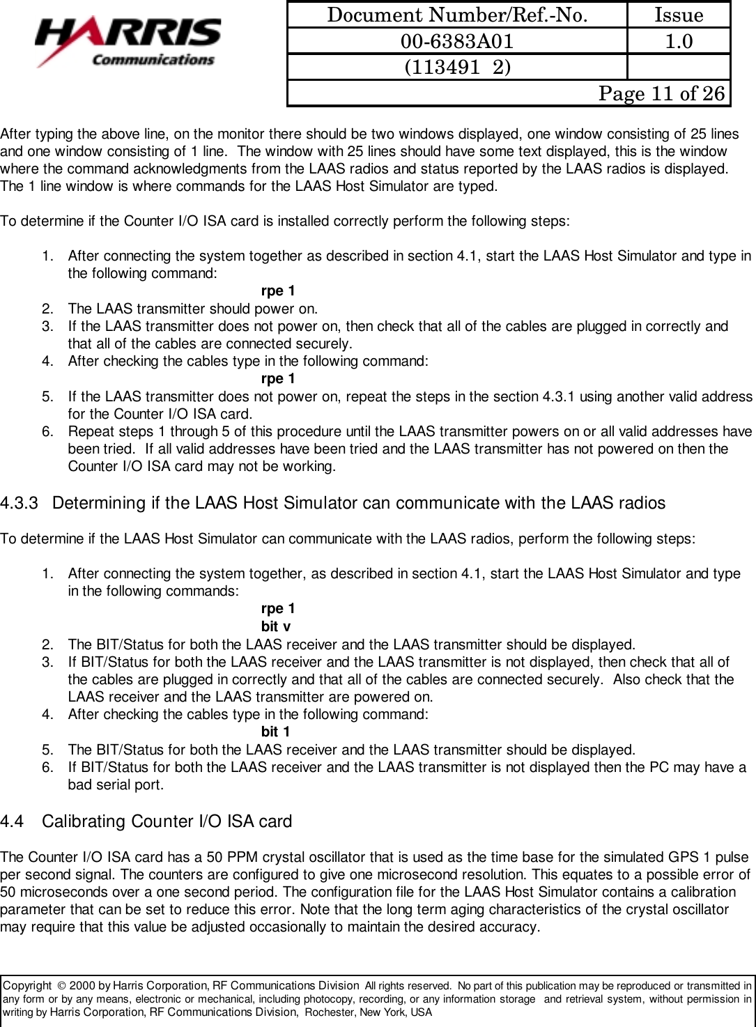
![Document Number/Ref.-No. Issue00-6383A01 1.0(113491 2) Page 16 of 26Copyright 2000 by Harris Corporation, RF Communications Division All rights reserved. No part of this publication may be reproduced or transmitted inany form or by any means, electronic or mechanical, including photocopy, recording, or any information storage and retrieval system, without permission inwriting by Harris Corporation, RF Communications Division, Rochester, New York, USA filename Limited to 8 characters, extension of bfr added to inputted filename Collects the following statistics to the inputted filename (in the order listed): received sequence number, missed bursts, accumulated missed bursts, CRC status (0-no error, 1-CRC error), accumulated CRC errors, FEC status (0-not used, 1-used), and received signal strength (dBm) d 0 Disables BFR statistics display d 1 Enables display of BFR statistics and displays last result--------------------dps [38400/57600/76800] [O/E/N]Allows the user to change the baud rate and the parity of the serial ports in use by the application. With no argument displays the current data port settings. [19200] - set the baud rate for both ports to 19,200 (This option added for debugging only!) [38400] - set the baud rate for both serial ports to 38,400 [57600] - set the baud rate for both serial ports to 57,600 [76800] - set the baud rate for both serial ports to 76,800 [O] - set the parity for both serial ports to Odd [E] - set the parity for both serial ports to Even [N] - set the parity for both serial ports to None (Note: the data bit count is fixed at 8 bits, and the stop bits are fixed at 1. )--------------------err [0] t MessageNumber r MessageNumberThis command is used to cause a command message sent from the LHS to a receiver or transmitter to have 1 fewerbyte or 1 more byte than specified by the ICD. In addition this command can be used to corrupt the CRC of aData Message. The chosen corruption (1 fewer byte, 1 more byte, or corrupted CRC) will occur the next time thecommand or Data Message is sent and only the next time. This command does not create a permanentcorruption of a command or Data Message. [0] Clear all errors t [1-18, 20] Transmitter only. 1 through 9 creates the selected command message with 1 fewer byte than specified in the ICD. 10 through 18 creates the selected command message with 1 more byte than specified in the ICD. 20 creates a Data Message with a corrupted CRC.](https://usermanual.wiki/Harris-RF-Communications-Division/VSR-4141-001.users-manual/User-Guide-113491-Page-16.png)
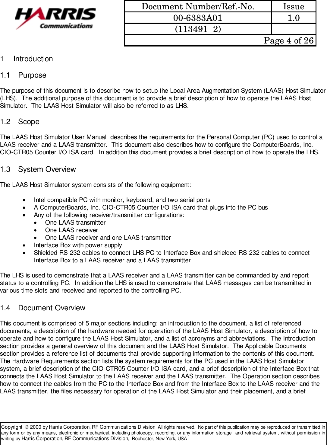
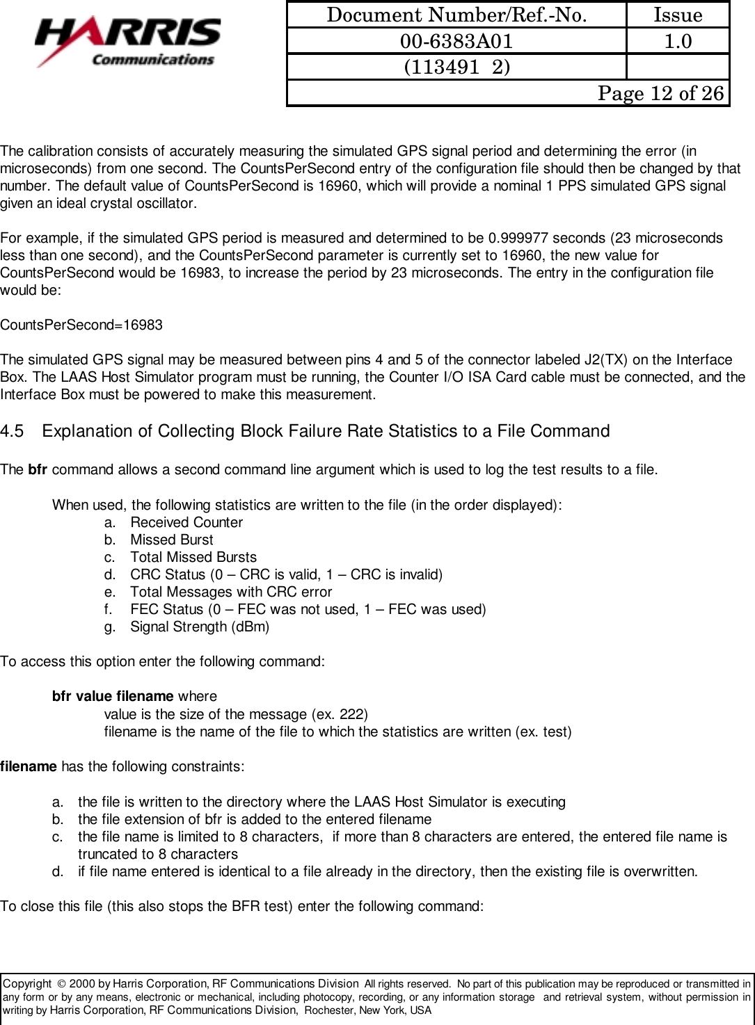
![Document Number/Ref.-No. Issue00-6383A01 1.0(113491 2) Page 17 of 26Copyright 2000 by Harris Corporation, RF Communications Division All rights reserved. No part of this publication may be reproduced or transmitted inany form or by any means, electronic or mechanical, including photocopy, recording, or any information storage and retrieval system, without permission inwriting by Harris Corporation, RF Communications Division, Rochester, New York, USA r [1-12] Receiver only. 1 through 6 creates the selected command message with 1 fewer byte than specified in the ICD. 7 through 12 creates the selected command message with 1 more byte than specified in the ICD.--------------------int frq pwr slt [v]Initializes the transmitter to the entered arguments. frq [1-400] Sets the Assigned Channel field of the Initialization Message to the entered value pwr [0-20] Sets the Assigned Power field of the Initialization Message to the entered value slt [1-ff] Bit field representing the assigned time slots. There are 8 assignable time slots. This bit field represents the 8 slots, with the LSB the earliest time slot (Assigned Time Slot 1). The bit in each position of the argument should be set to one if the corresponding slot is assigned, and to 0 if it is not assigned. A value of 0 is not allowed as input, but is the default value. [v] Display command response in verbose format--------------------inr frq [v]Initializes the receiver to the entered argument. frq [1-400] Sets the Assigned Channel field of the Initialization Message to the entered value [v] Display command response in verbose format--------------------mod [x/s/n] [t/r] [v]Reports/sets the current mode of the receiver, transmitter, or both. With no argument displays the current mode of the transmitter and receiver in hex format [x] Send a Mode Control Command Message to reset [t] transmitter, [r] receiver, or both [s] Send a Mode Control Command Message to set [t] transmitter, [r] receiver, or both to standby [n] Send a Mode Control Command Message to set [t] transmitter, [r] receiver or both to normal [v] Display the response in verbose format. The verbose switch is not sticky and applies only to the current request [r] Display the current mode of the receiver in hex format [t] Display the current mode of the transmitter in hex format--------------------](https://usermanual.wiki/Harris-RF-Communications-Division/VSR-4141-001.users-manual/User-Guide-113491-Page-17.png)
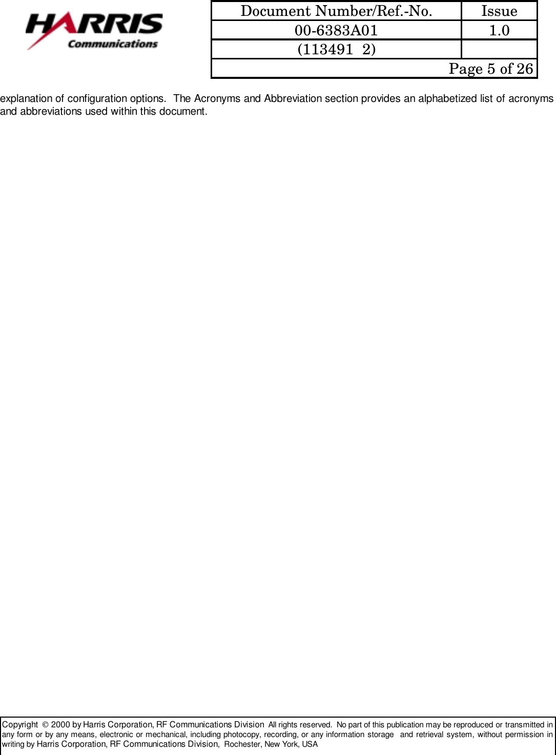
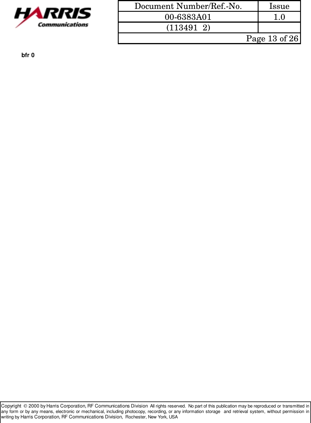
![Document Number/Ref.-No. Issue00-6383A01 1.0(113491 2) Page 18 of 26Copyright 2000 by Harris Corporation, RF Communications Division All rights reserved. No part of this publication may be reproduced or transmitted inany form or by any means, electronic or mechanical, including photocopy, recording, or any information storage and retrieval system, without permission inwriting by Harris Corporation, RF Communications Division, Rochester, New York, USAmon [0-8] [v/h]Controls the display of data from the receiver and provides a second method of controlling the display of BIT/Statusresponses from both the transmitter and receiver. With no agruments displays the current enable/disable status of displaying of data from the receiver and BIT/Status responses. [0-8] 0 = all BIT/Status and data display disabled 1 = Enable the transmitter BIT/Status response display 2 = Enable the receiver BIT/Status response display 3 = Enable both the receiver and transmitter BIT/Status display 4 = Enable display of transmitter and receiver BIT/Status responses and all the fields of the receiver data message with the exception of the data itself 5 = Enable display of all the fields of the receiver data message with the exception of the data itself 6 = Enable display of the data field of the receiver data message 7 = all BIT/Status, Data Message fields & data displays enabled 8 = Enable displaying of valid acknowledgement messages [v] Display response in verbose format [h] Display response in hex format--------------------bcr [t/r] Sends a Bit Clear Request to the receiver, transmitter or both. With no argument sends a BIT/Status Clear Command Message to both the receiver and the transmitter and displays the response in hex. [t] Sends a BIT/Status Clear Command Message to the transmitter and displays the response in hex [r] Sends a BIT/Status Clear Command Message to the receiver and displays the response in hex--------------------urm t/r [0-249] [v] Sends an unrecognized message to the receiver or the transmitter. t [0-249] Sends a message with the Message ID 0xFF to the transmitter having a Message Data of length [0-249] r [0-249] Sends a message with the Message ID 0xFF to the receiver having Message Data of length [0-249] [v] Display command response in verbose format--------------------](https://usermanual.wiki/Harris-RF-Communications-Division/VSR-4141-001.users-manual/User-Guide-113491-Page-18.png)
![Document Number/Ref.-No. Issue00-6383A01 1.0(113491 2) Page 19 of 26Copyright 2000 by Harris Corporation, RF Communications Division All rights reserved. No part of this publication may be reproduced or transmitted inany form or by any means, electronic or mechanical, including photocopy, recording, or any information storage and retrieval system, without permission inwriting by Harris Corporation, RF Communications Division, Rochester, New York, USAmra [0] [s/r] This command allows adjustment of the rate of data messages sent to from the LAAS Host Simulator to the transmitter. With no argument, displays the current skip value and the current message rate value. [0] Sets the message rate to be synchronized to the Transmitter Time Mark [s] Displays a menu alowing the user to select the SKIP value to be set (Range 0 - 255) [r] Displays a menu alowing the user to select the Message Rate to be set ( Range -25 to 25 (mS) )--------------------rpe [0/1]Remote Power Enable, controls the turning on and turning off of the transmitter. No argument displays the current state of the remote power enable line [0] Turns the transmitter off [1] Turns the transmitter on--------------------sdc [0/1] [v]Displays the current power source and allows changing the current power source. No argument displays the response to the current power source request in hex format [0] Sends a command message to switch the transmitter to the AC power source [1] Sends a command message to switch the receiver to the DC power source [v] Display command response in verbose format--------------------cwt 0/1 [v]Enables/disables the transmission of a constant waveform. 0 Stops the transmission of the CW signal 1 Starts the transmission of the CW signal. The current frequency and power settings are to be used](https://usermanual.wiki/Harris-RF-Communications-Division/VSR-4141-001.users-manual/User-Guide-113491-Page-19.png)
![Document Number/Ref.-No. Issue00-6383A01 1.0(113491 2) Page 20 of 26Copyright 2000 by Harris Corporation, RF Communications Division All rights reserved. No part of this publication may be reproduced or transmitted inany form or by any means, electronic or mechanical, including photocopy, recording, or any information storage and retrieval system, without permission inwriting by Harris Corporation, RF Communications Division, Rochester, New York, USA [v] Display command response in verbose format--------------------tce t/r [v]Sends a TCXO Adjustment Enable message to the receiver or the transmitter. t Send a TCXO Adjustment Enable Command Message to the transmitter r Send a TCXO Adjustment Enable Command Message to the receiver [v] Display command response in verbose format--------------------tcd t/r 0/1 [v]Sends a TCXO Adjustment Direction message to the receiver or the transmitter. t Send a TXCO Adjustment Direction Command Message to the transmitter r Send a TXCO Adjustment Direction Command Message to the receiver 0 Decrease the frequency 1 Increase the frequency [v] Display command response in verbose format--------------------verDisplays the version of the LHS, receiver software (DSP and MICRO), receiver hardware, transmitter software (DSPand MICRO), and transmitter hardware (PA and PS) An example printout: LHS 23 TX DSP 10 TX MICRO 11 TX PA 11 TX PS 20 RX DSP 20 RX MICRO 11--------------------](https://usermanual.wiki/Harris-RF-Communications-Division/VSR-4141-001.users-manual/User-Guide-113491-Page-20.png)
![Document Number/Ref.-No. Issue00-6383A01 1.0(113491 2) Page 21 of 26Copyright 2000 by Harris Corporation, RF Communications Division All rights reserved. No part of this publication may be reproduced or transmitted inany form or by any means, electronic or mechanical, including photocopy, recording, or any information storage and retrieval system, without permission inwriting by Harris Corporation, RF Communications Division, Rochester, New York, USAtme [t/r] 0/1 Time Mark Enable control. Not selecting t or r enables/disables time marks for both the receiver and the transmitter. [t] Enable/Disable transmitter time mark [r] Enable/Disable receiver time mark 0 Disables time mark1 Enables time mark--------------------tmp [0] t/r Time Mark Period control. t Menu for adjusting the time mark period of the transmitter is displayed r Menu for adjusting the time mark period of the receiver is displayed [0] Selects "perfect" time mark period setting for both the transmitter and the receiver t 0 Sets "perfect" time mark period for the transmitter r 0 Sets "perfect" time mark period for the receiver--------------------tmo [0] Receiver Time Mark Offset With no arguments, displays a menu which allows the user to change the time mark offset for the Receiver. [0] Sets the receiver time mark offset back to zero (i.e. perfect synchronization with the transmitter time mark signal)--------------------clsThis command causes the application to clear the screen.--------------------](https://usermanual.wiki/Harris-RF-Communications-Division/VSR-4141-001.users-manual/User-Guide-113491-Page-21.png)
![Document Number/Ref.-No. Issue00-6383A01 1.0(113491 2) Page 22 of 26Copyright 2000 by Harris Corporation, RF Communications Division All rights reserved. No part of this publication may be reproduced or transmitted inany form or by any means, electronic or mechanical, including photocopy, recording, or any information storage and retrieval system, without permission inwriting by Harris Corporation, RF Communications Division, Rochester, New York, USAexitThis command causes the application to terminate.--------------------log [start/stop/reset/filename] [filename.ext] Control the logging of data. With no arguments, terminates data logging. [start] Begin logging all transmitted and received data to a data log file named "LOGFILE.TXT". Data is appended to the existing log file if one exists, else a new file is created. [stop] Terminate data logging [reset] Causes the log file to be deleted and, if logging is currently enabled a new log file is created [filename.ext] logfile.txt Sets the logging file name to "logfile.txt"--------------------scrn 0/1Set the number of rows displayed on the screen. This command clears the screen and repositions the cursor to thetop line of the screen. 0 Set number of lines on screen to 25 1 Set number of lines on screen to 50--------------------tick [0/1] Causes a single character, a '-', to be displayed once per second. With no arguments, displays whether the tick option is enabled or disabled. 0 disables this option1 enables this option--------------------show [text] Causes the text following the command "show" to be displayed on the screen. This text is displayed in Light Grey.--------------------](https://usermanual.wiki/Harris-RF-Communications-Division/VSR-4141-001.users-manual/User-Guide-113491-Page-22.png)
![Document Number/Ref.-No. Issue00-6383A01 1.0(113491 2) Page 23 of 26Copyright 2000 by Harris Corporation, RF Communications Division All rights reserved. No part of this publication may be reproduced or transmitted inany form or by any means, electronic or mechanical, including photocopy, recording, or any information storage and retrieval system, without permission inwriting by Harris Corporation, RF Communications Division, Rochester, New York, USArun filename.extCauses the application to read "filename.ext" and accept commands from this file as though they were typed in on thecommand line.--------------------pause 0/1This command stops the displaying of data or re-enables the displaying of data on the screen. 1 Stops all data display activity 0 Re-enables data display activity.--------------------flag [v/h/s/d] [0/1] Displays/Controls the states of the "Sticky" flags. With no command parameters this command displays the enable/disable state of all of the "Sticky" flags. v Verbose Flag h Hexidecimal Display Flag s Show Bit/Status Flag d Debug Flag (much debug data displayed) 0 Disabled1 Enabled--------------------txmsg xx xx xx xx xx xx xxCauses the message described by "xx xx xx xx xx xx xx" to be sent to the Transmitter. The message is made up of 1or more hexadecimal bytes shown above as "xx". A message is made up of a series of 2 character ASCII/hexcharacters, each representing a byte of data. For example: txmsg aa 55 01 01 f0 0f--------------------rxmsg xx xx xx xx xx xx xxCauses the message described by "xx xx xx xx xx xx xx" to be sent to the Receiver. The message is made up of 1 ormore hexadecimal bytes shown above as "xx". A message is made up of a series of 2 character ASCII/hexcharacters, each representing a byte of data. For example: rxmsg aa 55 01 01 f0 0f](https://usermanual.wiki/Harris-RF-Communications-Division/VSR-4141-001.users-manual/User-Guide-113491-Page-23.png)