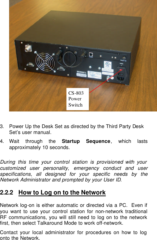
HARRIS CS803 Digital Trunked Control Station User Manual CS 803 Operators Manual Rev C
Harris Corporation Digital Trunked Control Station CS 803 Operators Manual Rev C
UserManual.wiki
>
HARRIS
>
CS803 User Manual
Manual
Navigation menu
Upload a User Manual
Namespaces
Wiki Guide
HTML
PDF
Info
Views
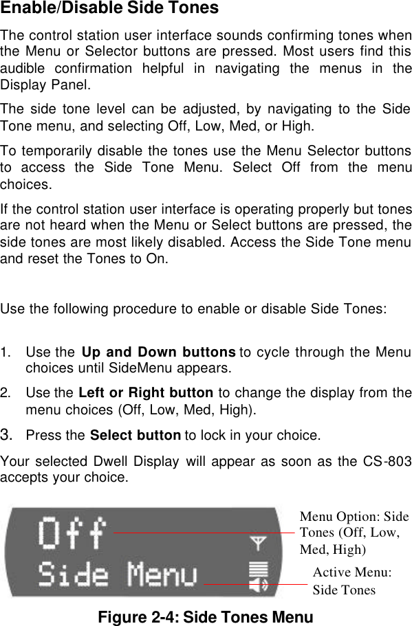
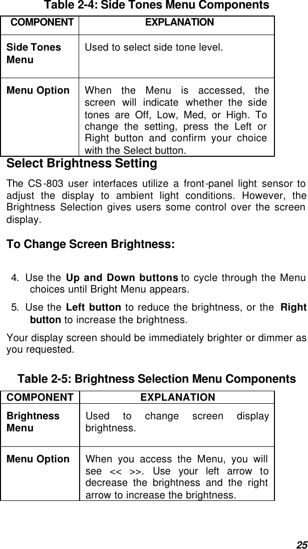
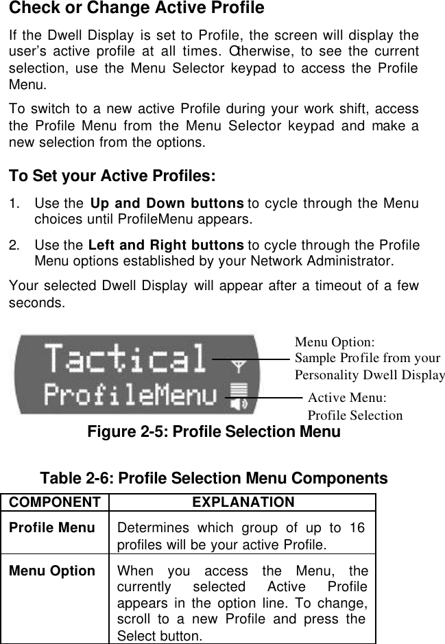
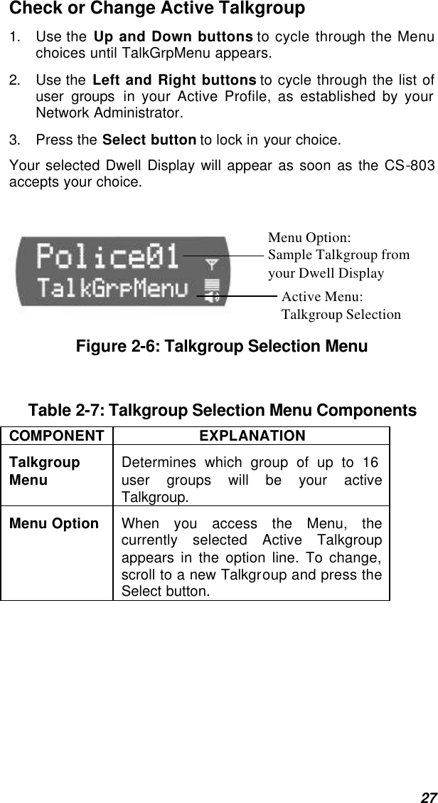
User Manual
Discussion / Help
Navigation