HARRIS MBS800B075 OpenSky 800 MHz Base Station User Manual Manual
Harris Corporation OpenSky 800 MHz Base Station Manual
UserManual.wiki
>
HARRIS
>
MBS800B075 User Manual
Manual
Navigation menu
Upload a User Manual
Namespaces
Wiki Guide
HTML
PDF
Info
Views
User Manual
Discussion / Help
Navigation

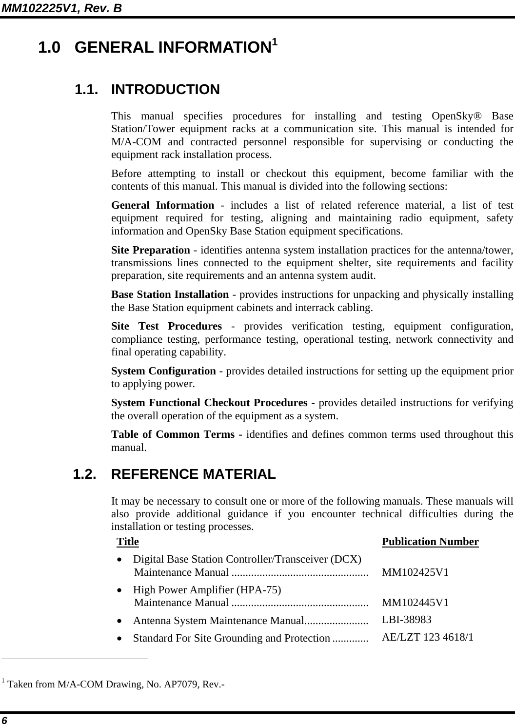
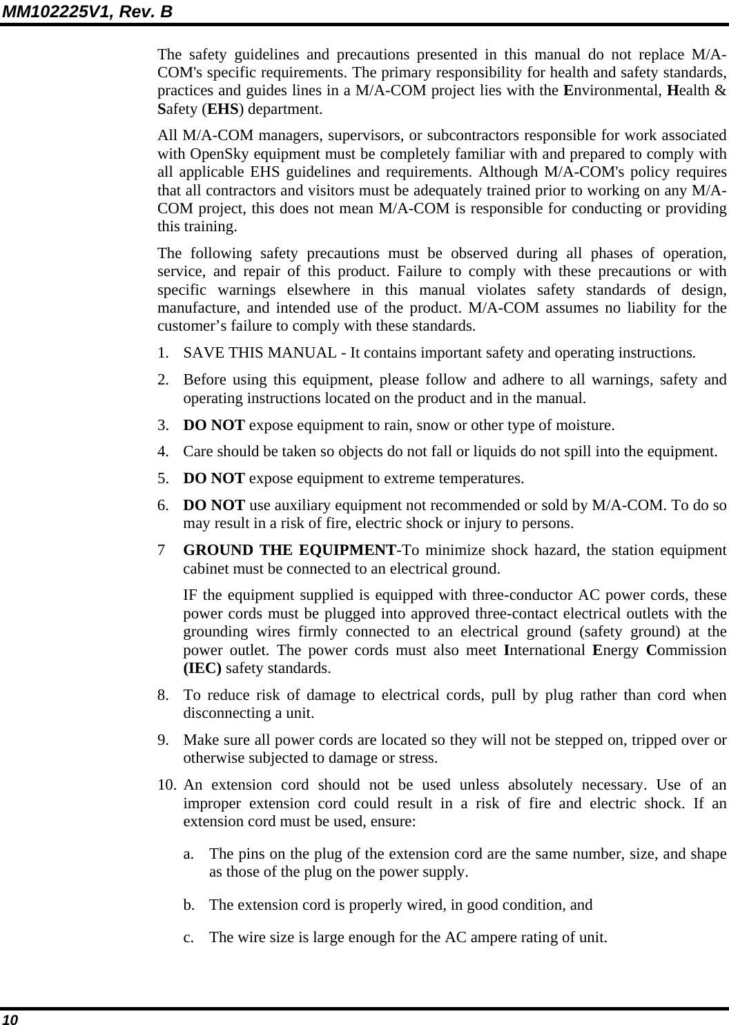
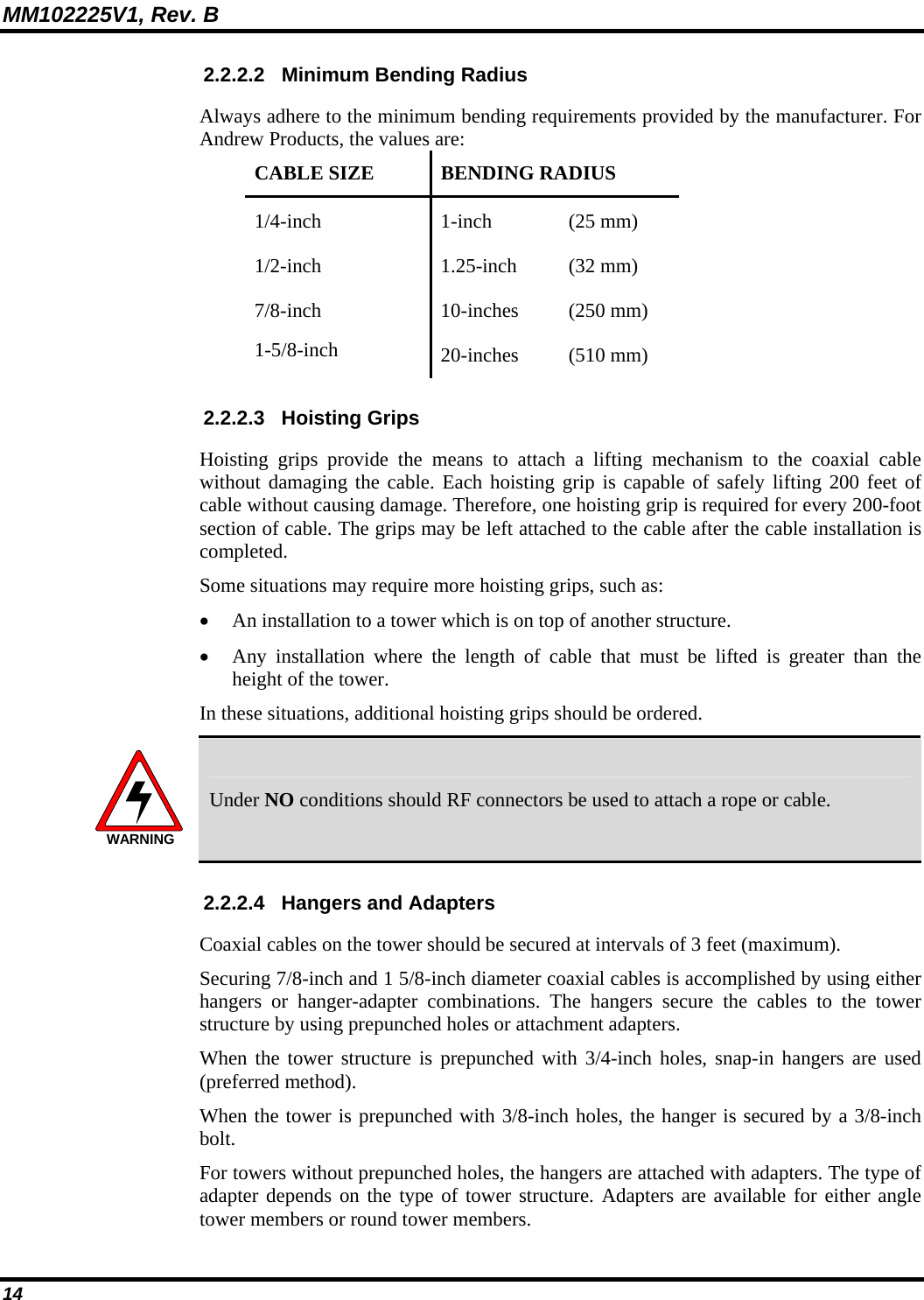
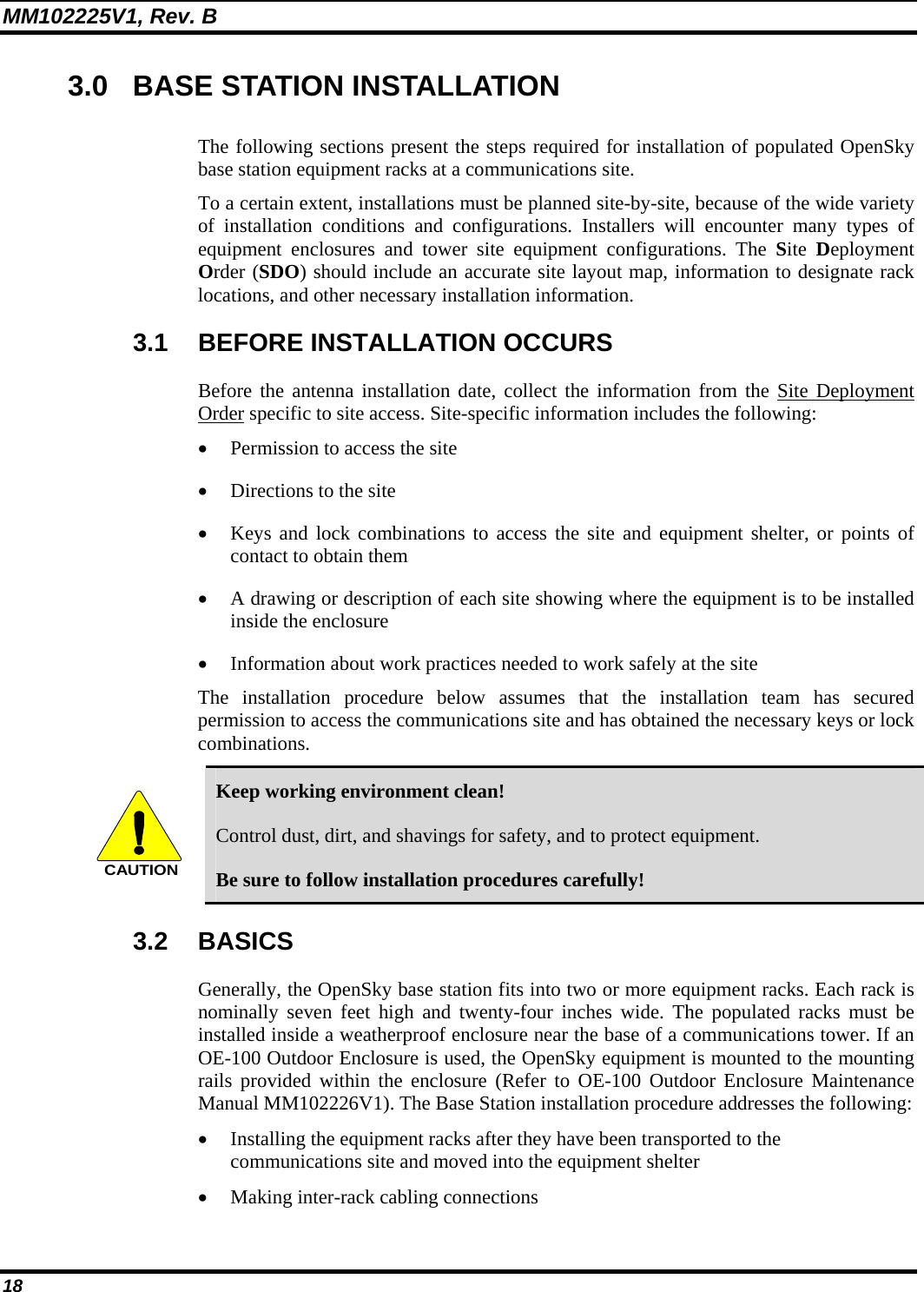
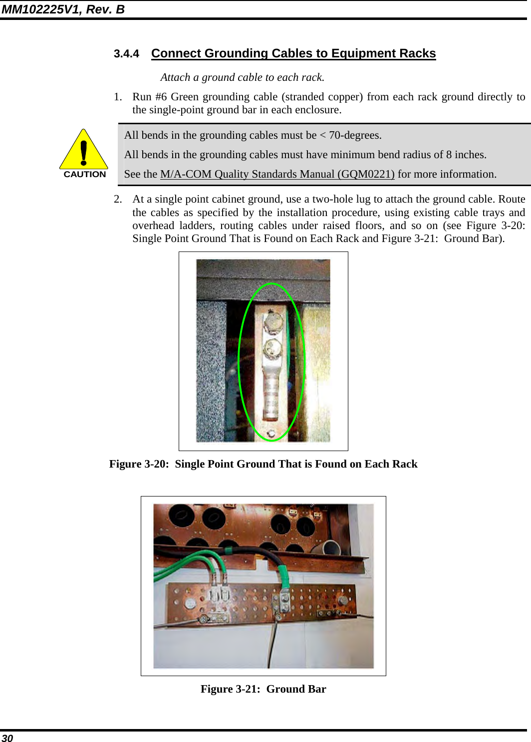
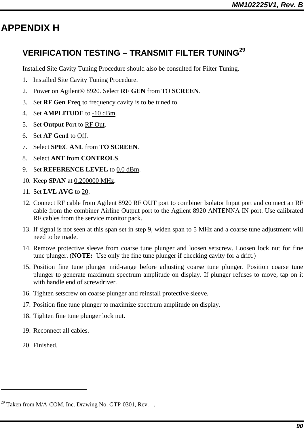
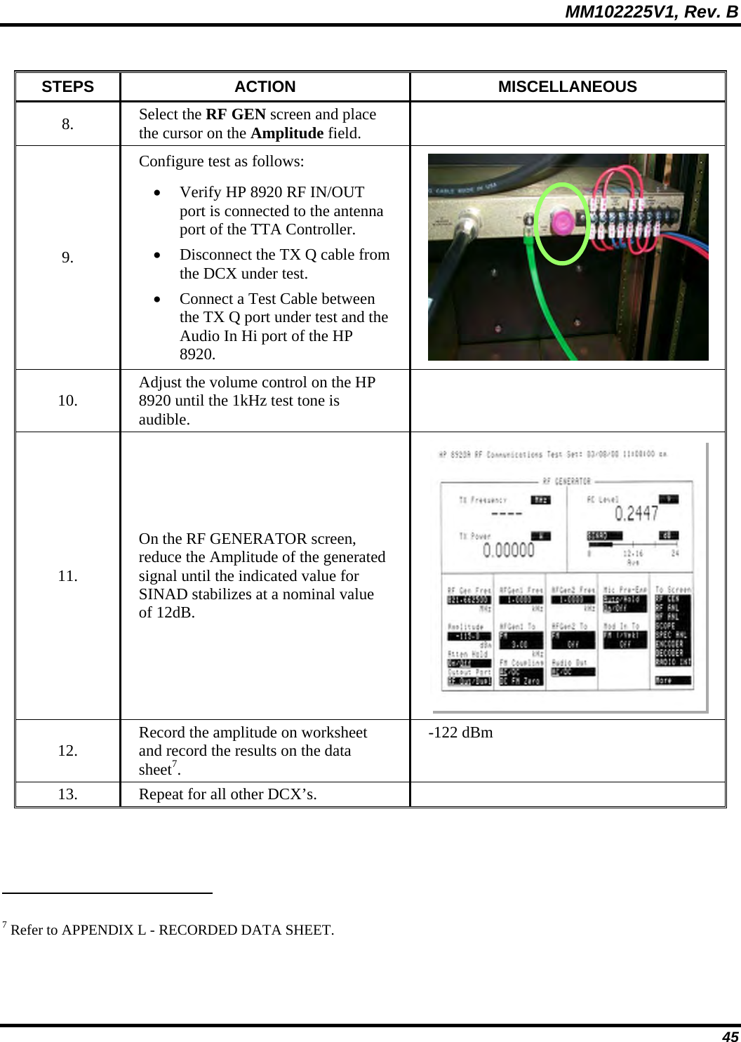
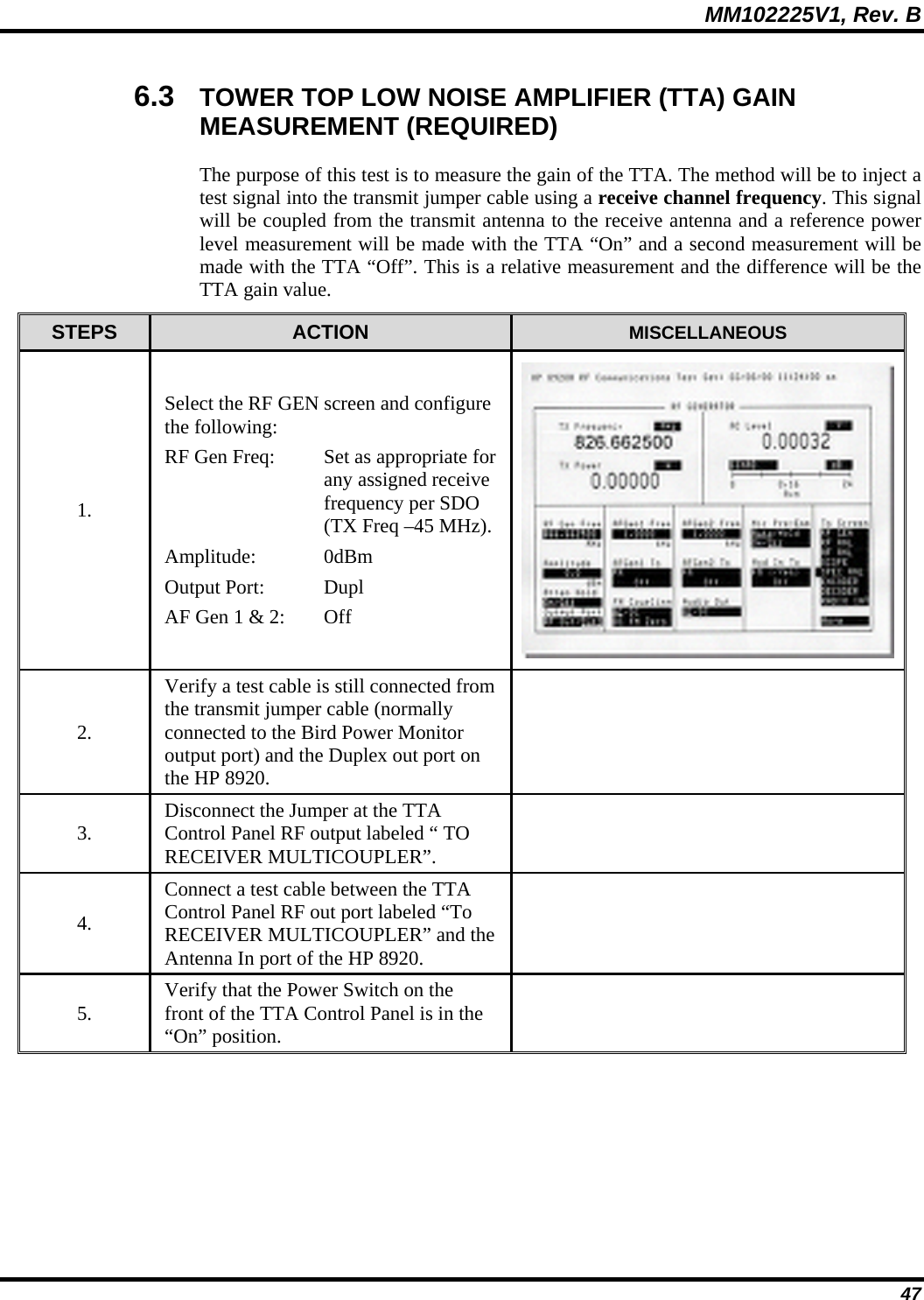
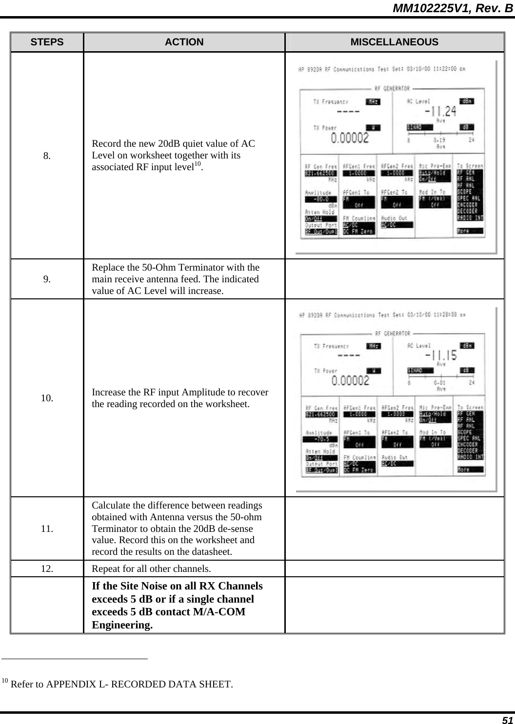
![MM102225V1, Rev. B 44 STEPS ACTION MISCELLANEOUS 3. To place the DCX in Analog Mode, enter the sequence of commands indicated by bold script in the example seen to the right. Offline [CR] ;<Various status messages> at@outmode0 [CR] OK save_config [CR] OK Reboot [CR] ; < The Base Station Reboots> 4. Repeat Steps 1 and 2 for all other DCX units. 5. Ensure that the DCX and HPA under test are powered up and the HPA is offline. 6. On the HP 8920, select the RF GEN screen and set the following configuration, (see adjacent photo): RF Gen Freq: Set for the receive frequency of the RF path under test (45MHz below the Transmit Frequency) . Amplitude: -80 dBm Output Port: RF Out AFGen1 Freq: 1kHz AFGen1 To: FM 3kHz AFGen2 To: Off AC Level: Set to dBm plus 10 sample averaging SINAD dB: Set for an averaging value of 10 samples 7. Select the AFANL screen and set the following configuration: AF Anl In: Audio In Filter 1: 300Hz HPF Filter 2: 3kHz LPF De-Emphasis: 750 µsec Detector: rms](https://usermanual.wiki/HARRIS/MBS800B075/User-Guide-964953-Page-45.png)
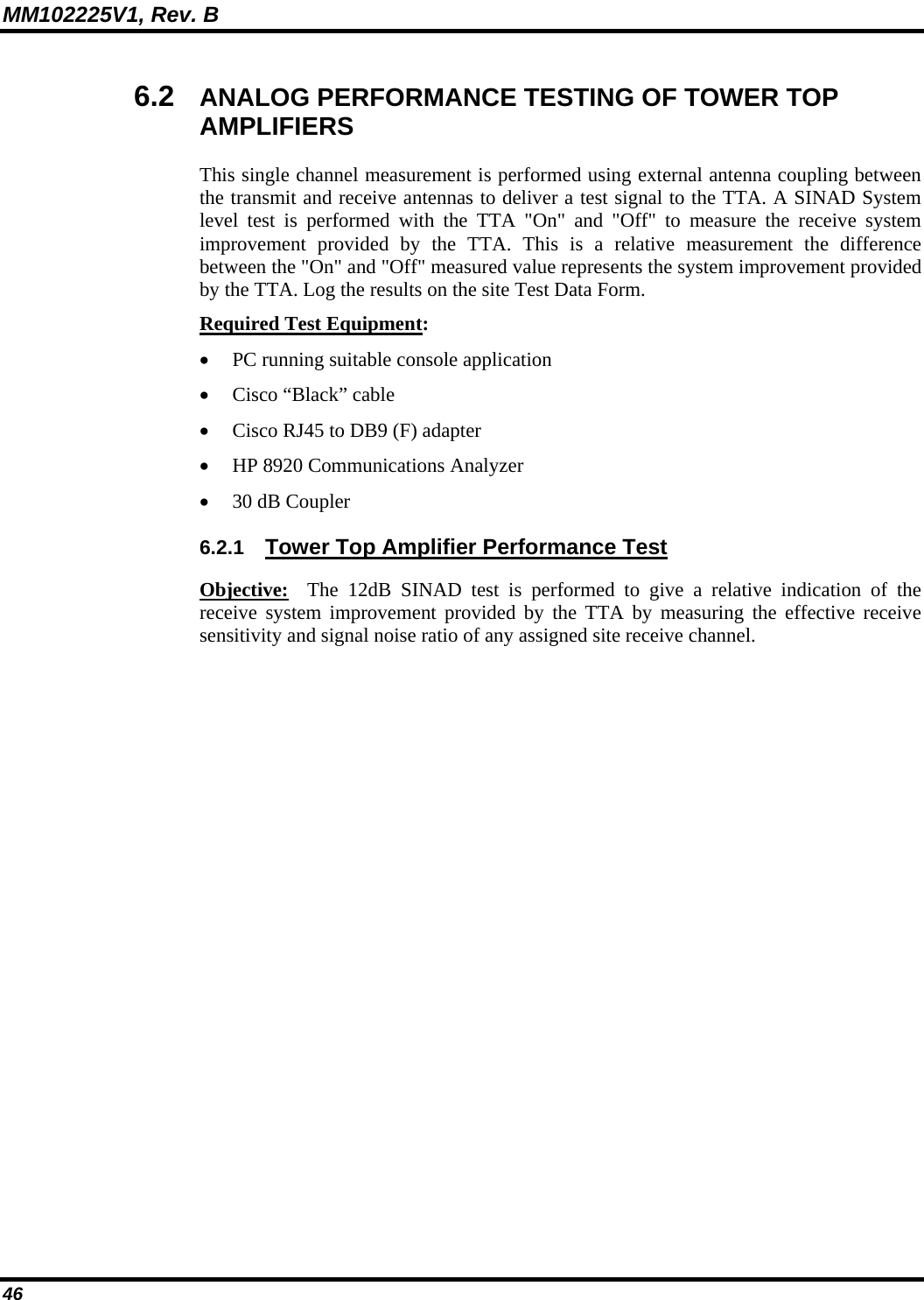
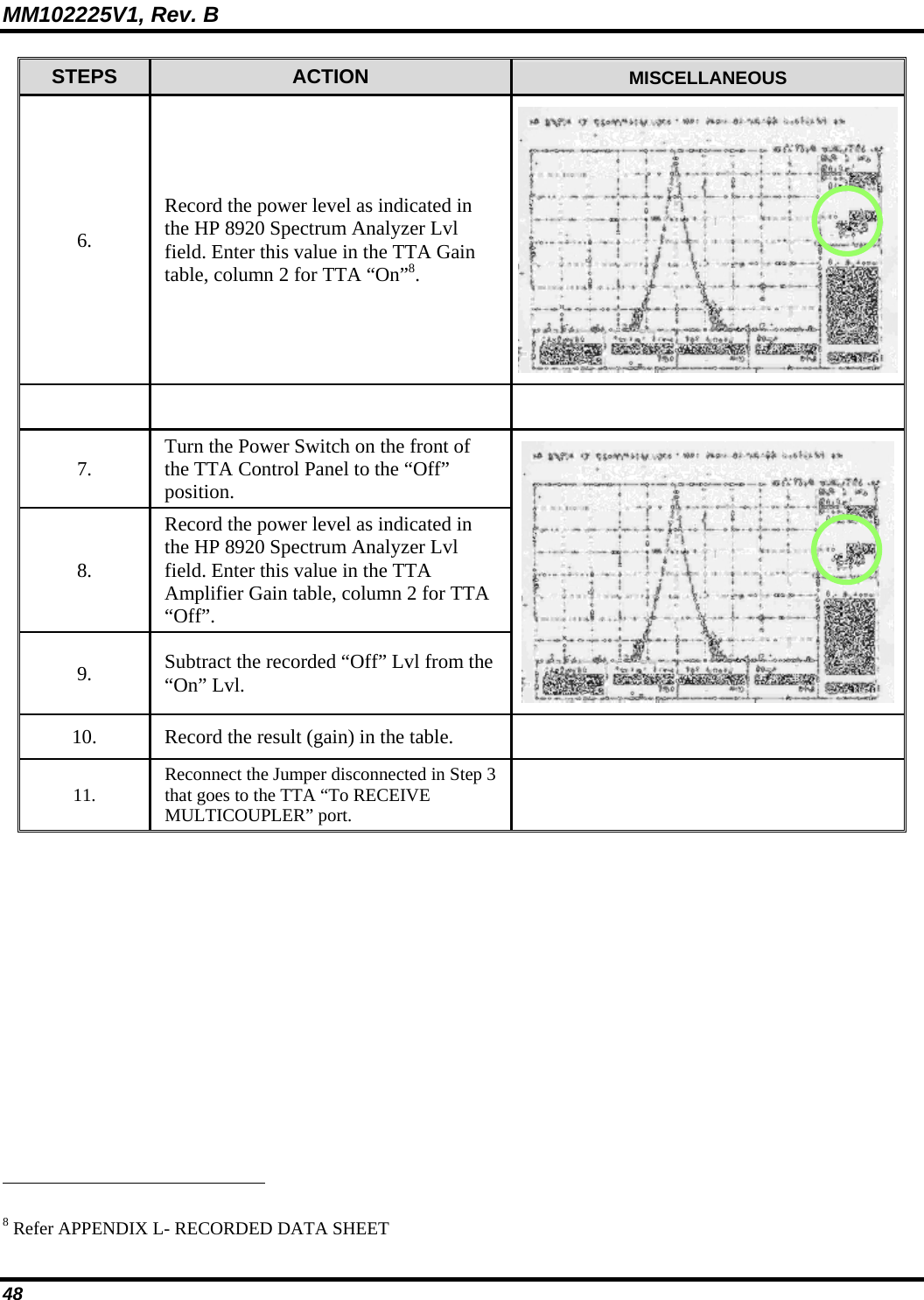
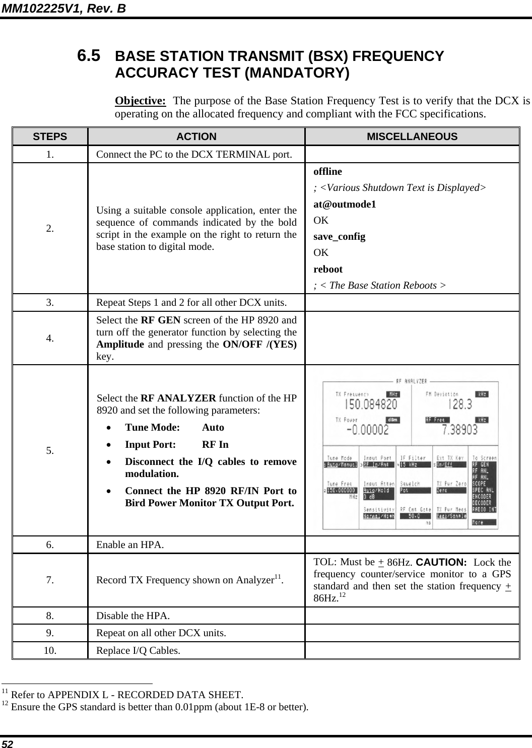
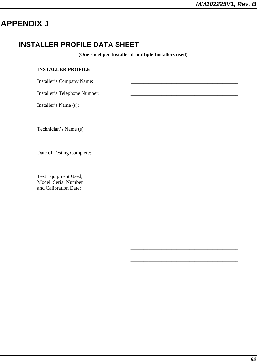
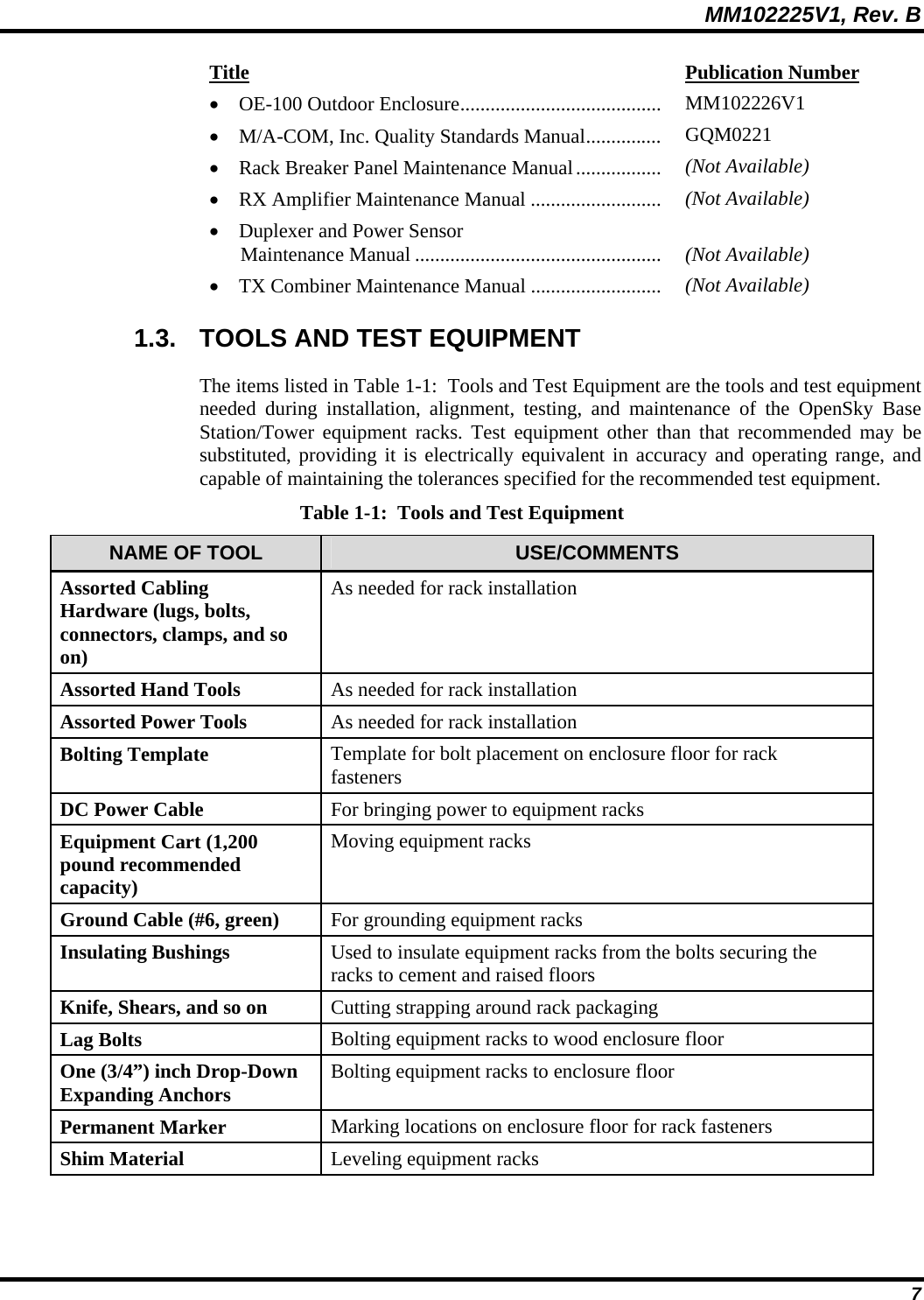
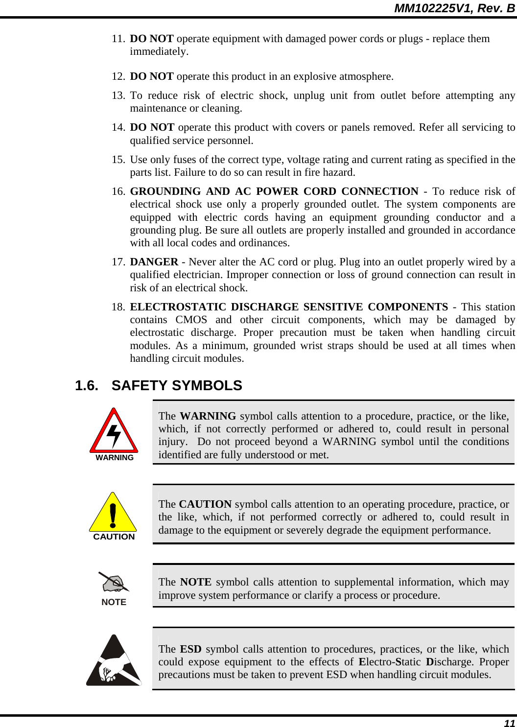
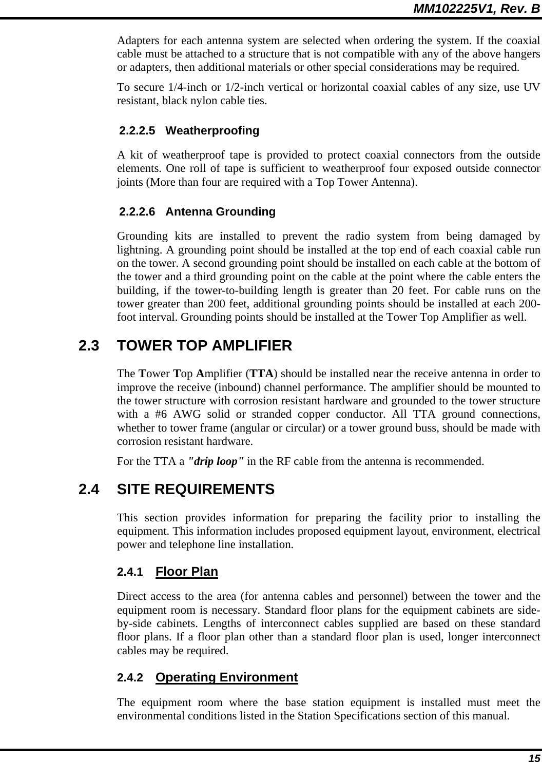
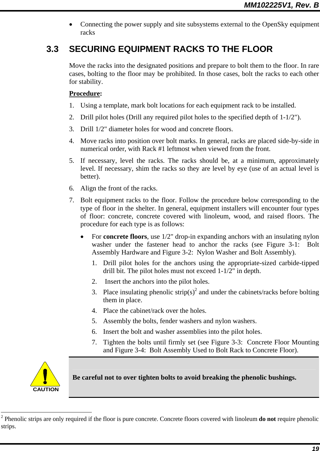
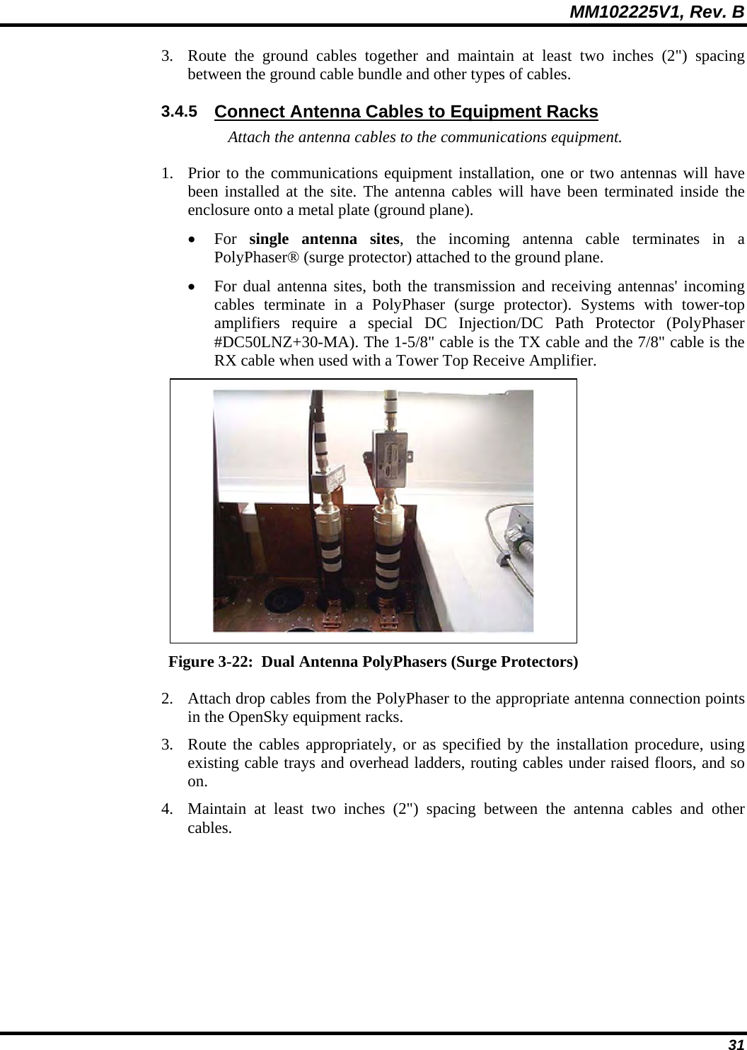
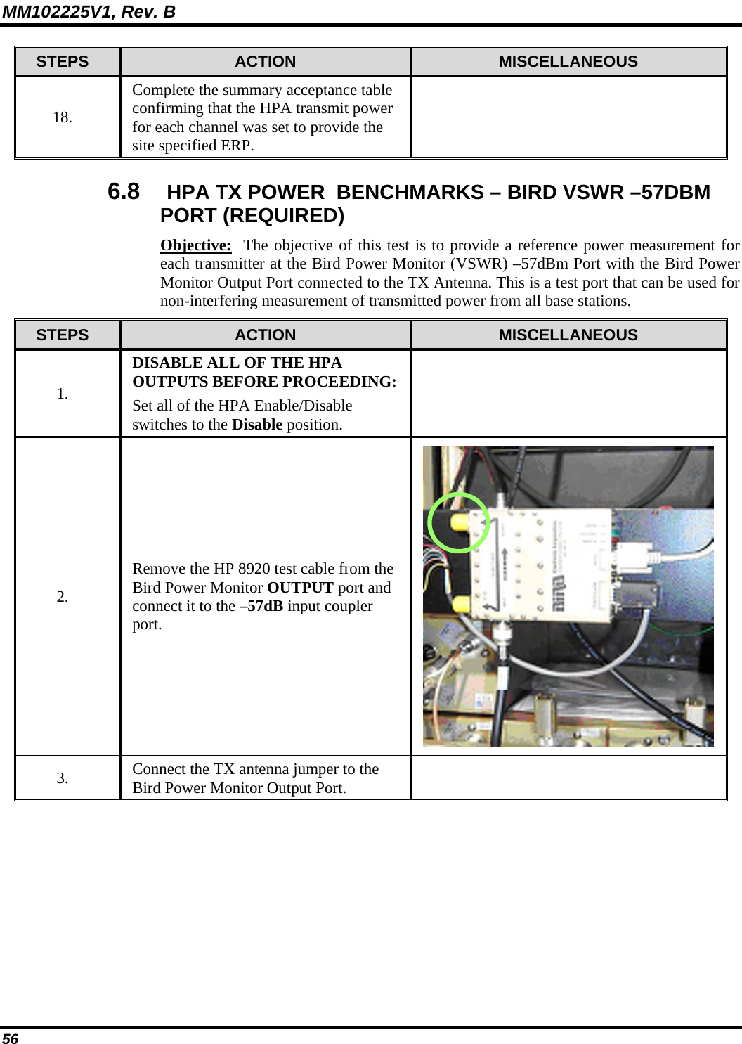
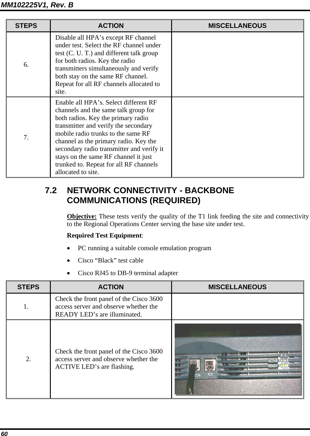
![MM102225V1, Rev. B 55 STEPS ACTION MISCELLANEOUS 9. Press the Enter key on the laptop keyboard. The status information on the right will be displayed on the PC console application. Similar to the text found on the right. Example: buck40:14 buck40-bs1> Setting the HPA TX Power 10. Enter the command: at@hpapowerN [CR] Example: Where N is the desired HPA power setting to overcome rack losses. 11. Set the HPA Disable/Enable switch to Enable. 12. The HPA will send the message shown on the right via the DCX to the console display and start transmitting. HPA> RF enabled by front panel switch. 13. Compare the measured value TX Power on the HP 8920 to the desired level, repeating steps 10-12 as necessary to fine-tune the measured level to set the prescribed Site ERP. Note: There may be a slight variation between the commanded and measured power levels. This may be due to test cable losses. Be sure to factor these into the measurement process. Example: Output Power 43dBm Test Cable Loss -.8dB HP 8920 Reading 42.2dBm 14. When the final value for TX Power is achieved, enter the commands on the right. save_config [CR] reboot [CR] 15. After the DCX has completed its boot cycle record the final measured HPA TX Power level on the collection sheet and data sheet15. 16. Set the tested HPA Enable/Disable switch to the Disable position. 17. Repeat for each RF channel, leaving tested HPA’s in the DISABLED mode. 14 "Buck40", where used in this manual, is only an example of the applicable code. 15 Refer to APPENDIX L - RECORDED DATA SHEET.](https://usermanual.wiki/HARRIS/MBS800B075/User-Guide-964953-Page-56.png)
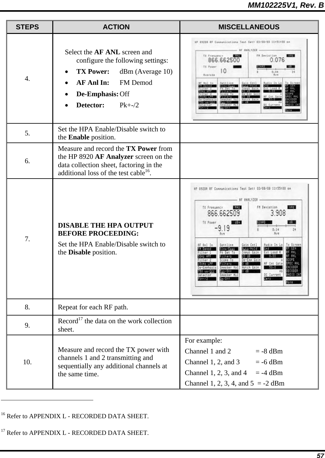
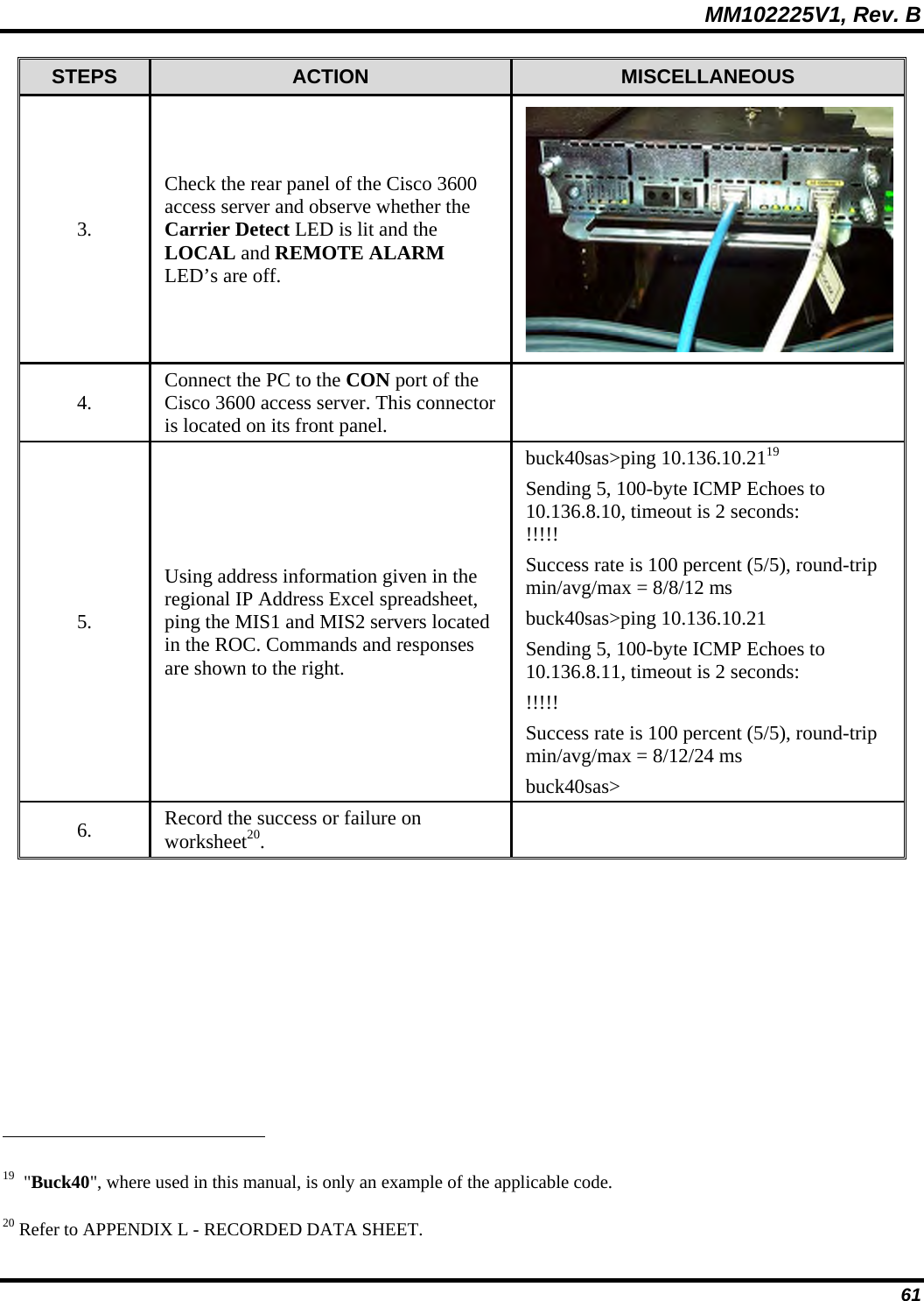
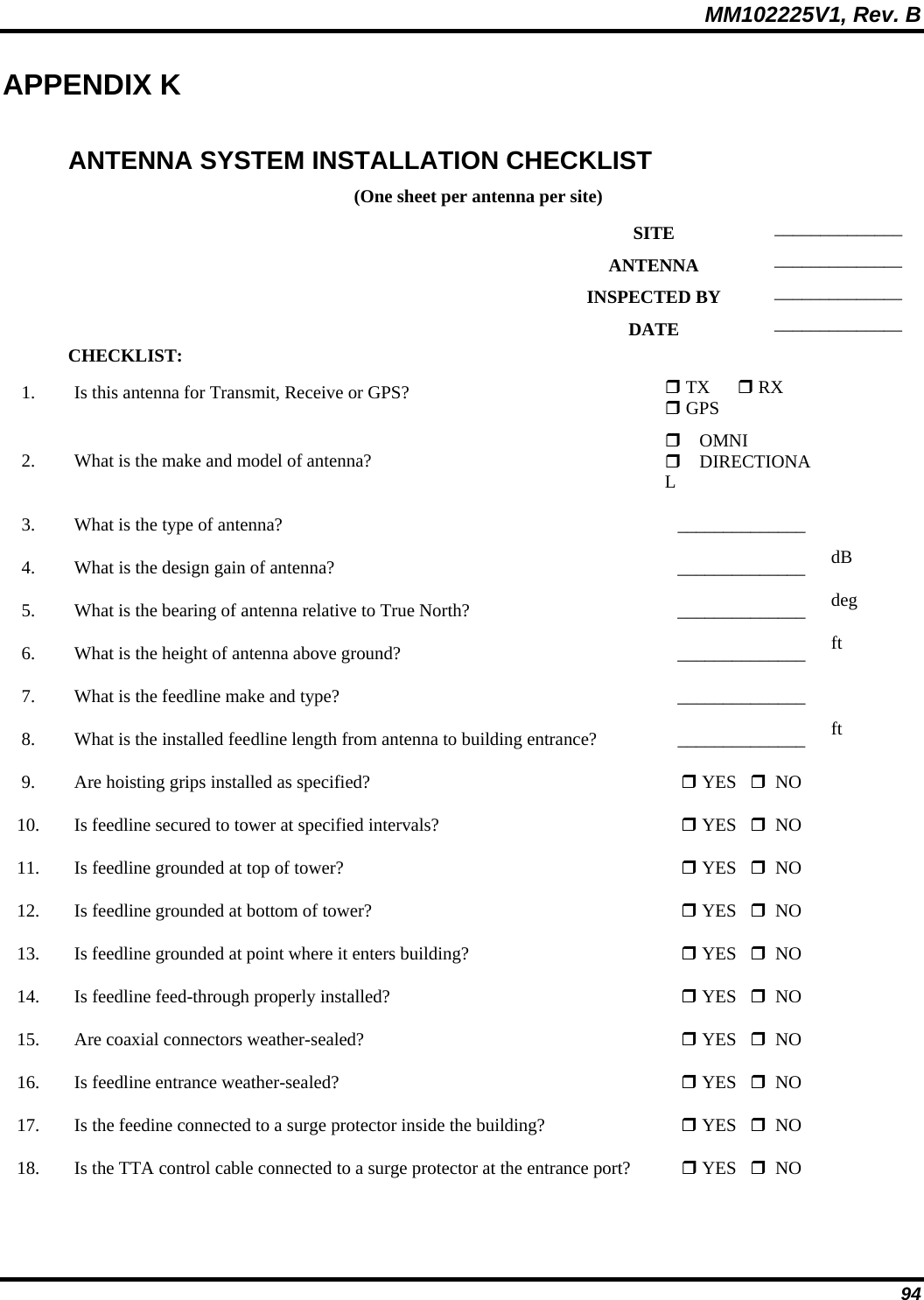
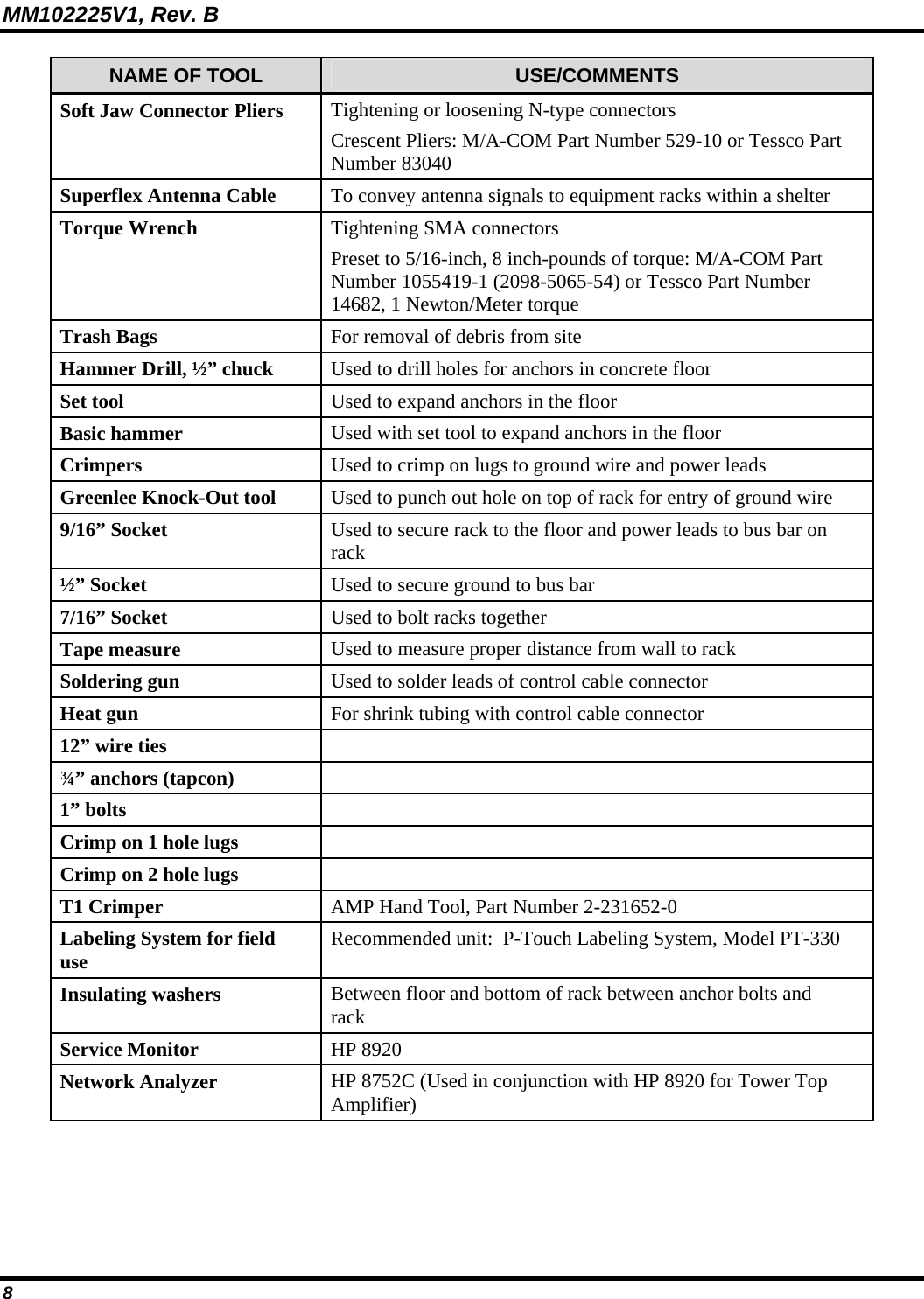
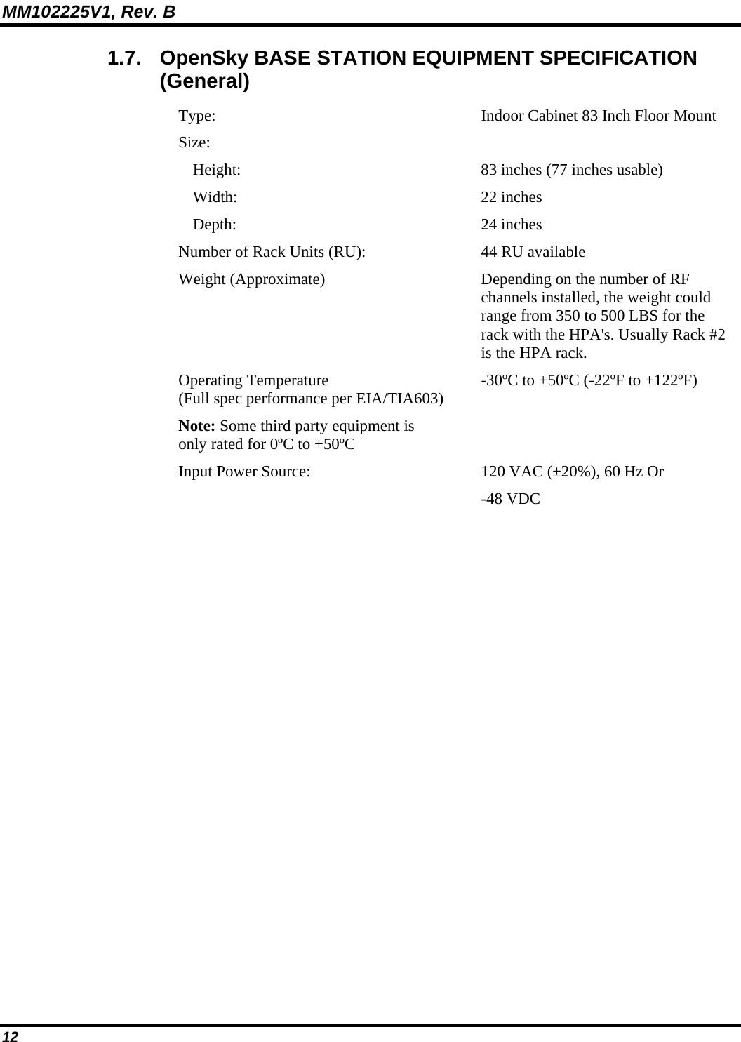
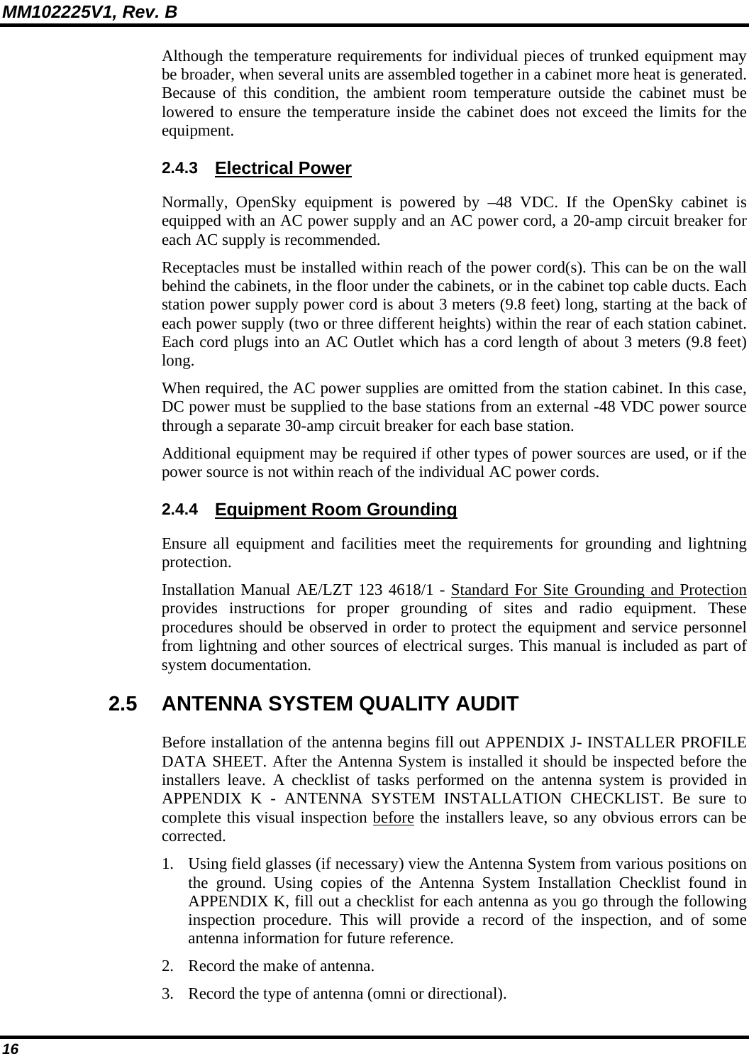
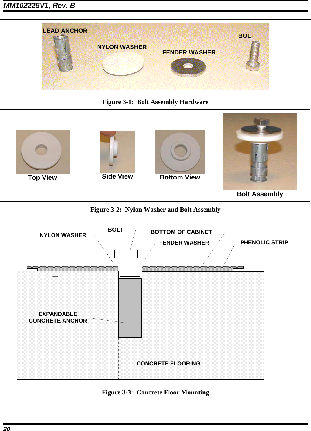
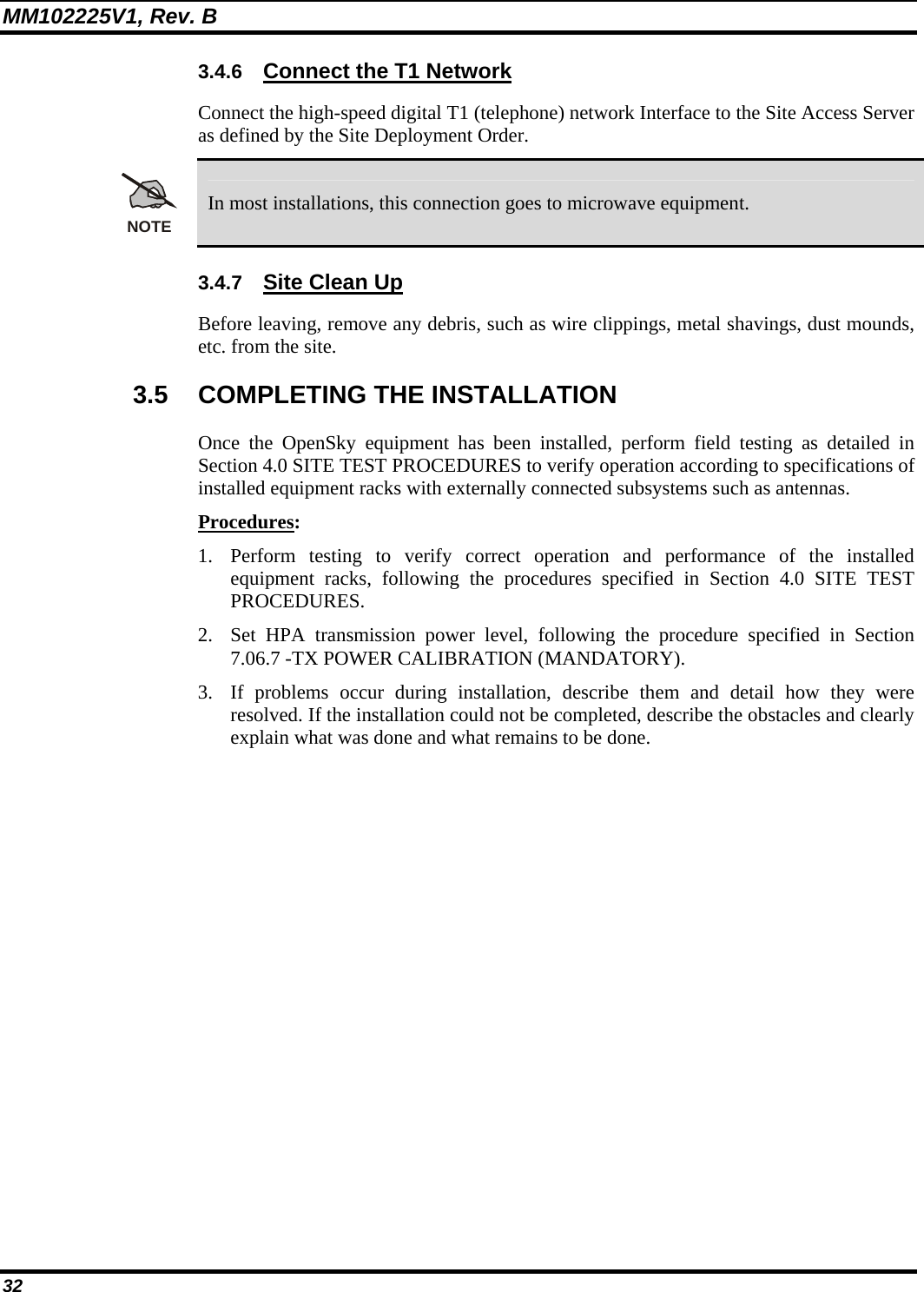
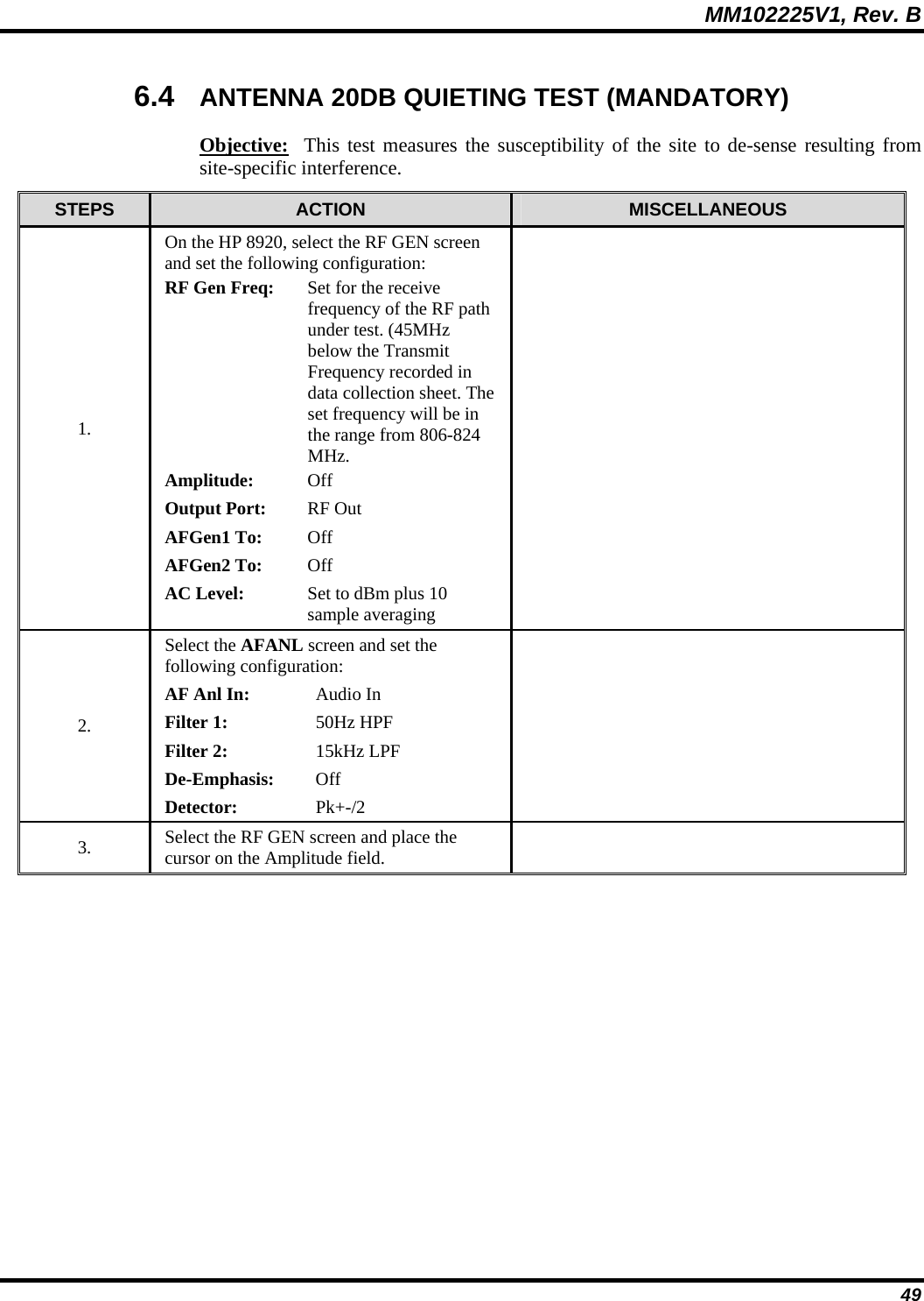
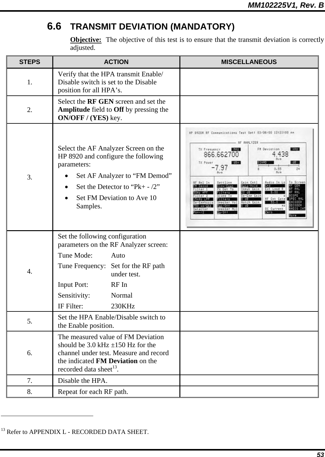
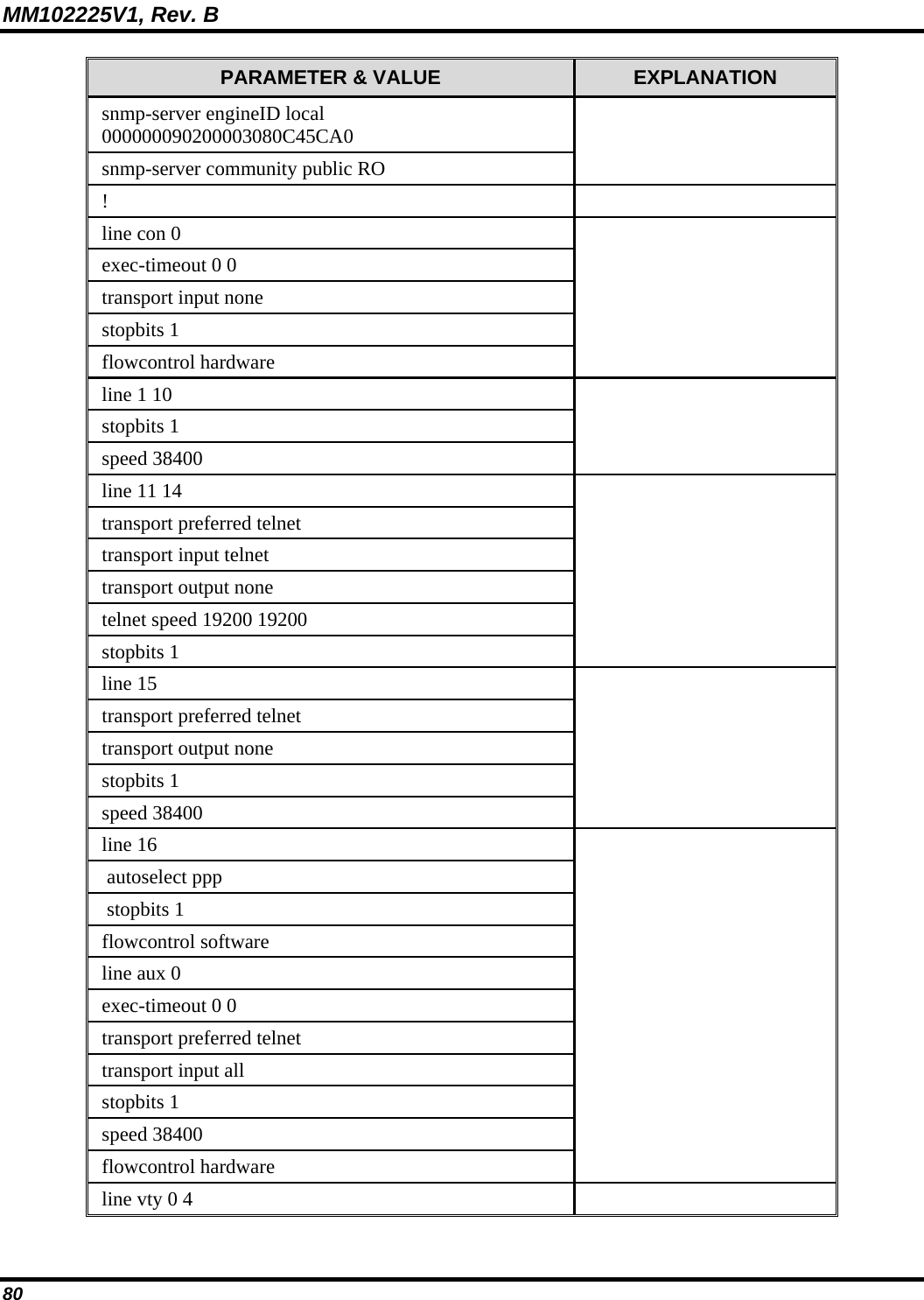
![MM102225V1, Rev. B 62 7.3 T1 QUALITY LINK Objective: The Cisco 3600 provides comprehensive monitoring capabilities for the T1 port that carries data traffic over the communications backbone. The showcontroller command accumulates statistics over sixteen 15-minute intervals. This test does not form part of the site acceptance testing but is included as a diagnostic tool to aid resolution of link related issues. STEPS ACTION MISCELLANEOUS 1. Allow the Unit to operate with the T1 connected for at least 5 minutes. 2. Using a PC connected to the Cisco CONSOLE port, enter the following command from the enabled prompt: buck40sas# show contr t1 1/0 [CR]21 The 3600 will respond with the Status Information on the right. T1 1/0 is up Applique type is Channelized T1 Cable length is long gain36 0db No alarms detected Framing is ESF, Line Code is B8ZS, Clock Source is Line Data in current interval (741 seconds elapsed): 0 Line Code Violations, 0 Path Code Violations 0 Slip Secs, 0 Fr Loss Secs, 0 Line Err Secs, 0 Degraded Mins 0 Errored Secs, 0 Bursty Err Secs, 0 Severely Err Secs, 0 Unavail Secs Data in Interval 1: 0 Line Code Violations, 0 Path Code Violations 0 Slip Secs, 0 Fr Loss Secs, 0 Line Err Secs, 0 Degraded Mins 0 Errored Secs, 0 Bursty Err Secs, 0 Severely Err Secs, 0 Unavail Secs Data in Interval 2: 0 Line Code Violations, 0 Path Code Violations 0 Slip Secs, 0 Fr Loss Secs, 0 Line Err Secs, 0 Degraded Mins 0 Errored Secs, 0 Bursty Err Secs, 0 Severely Err Secs, 0 Unavail Secs Continued 21 "Buck40", where used in this manual, is only an example of the applicable code.](https://usermanual.wiki/HARRIS/MBS800B075/User-Guide-964953-Page-63.png)
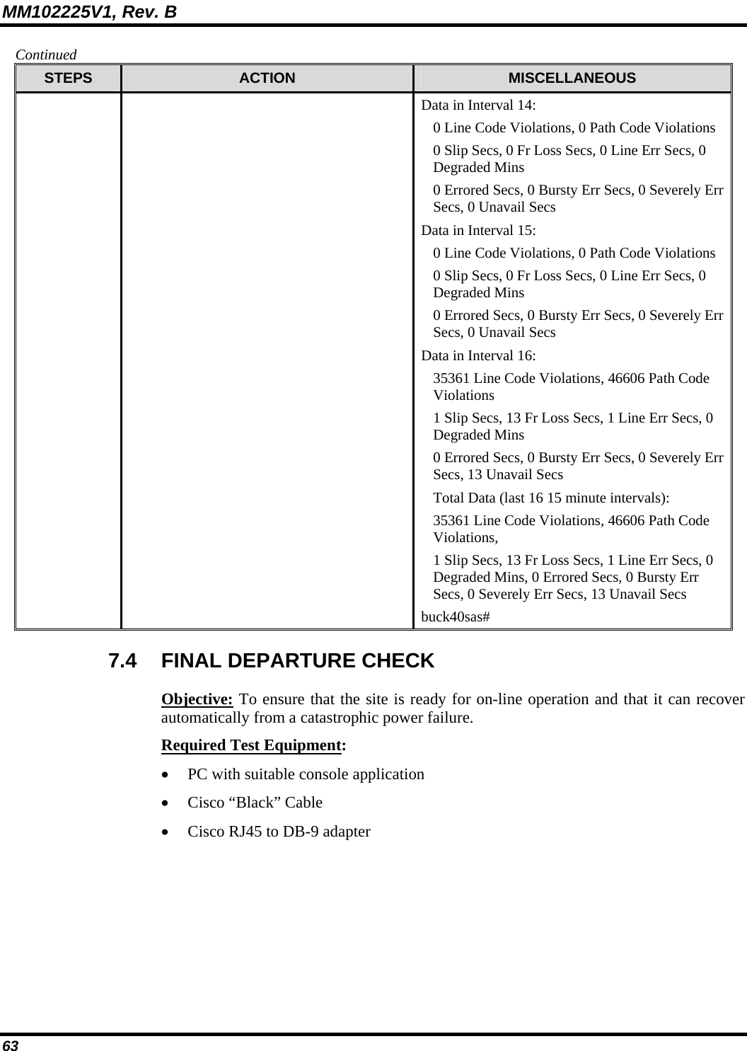
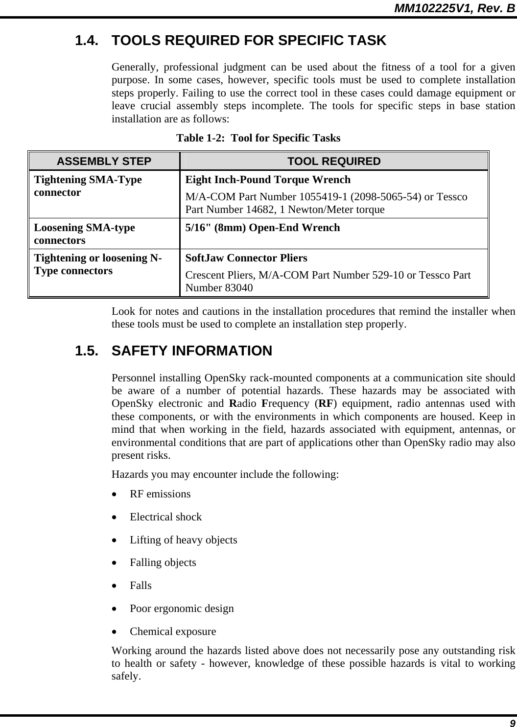
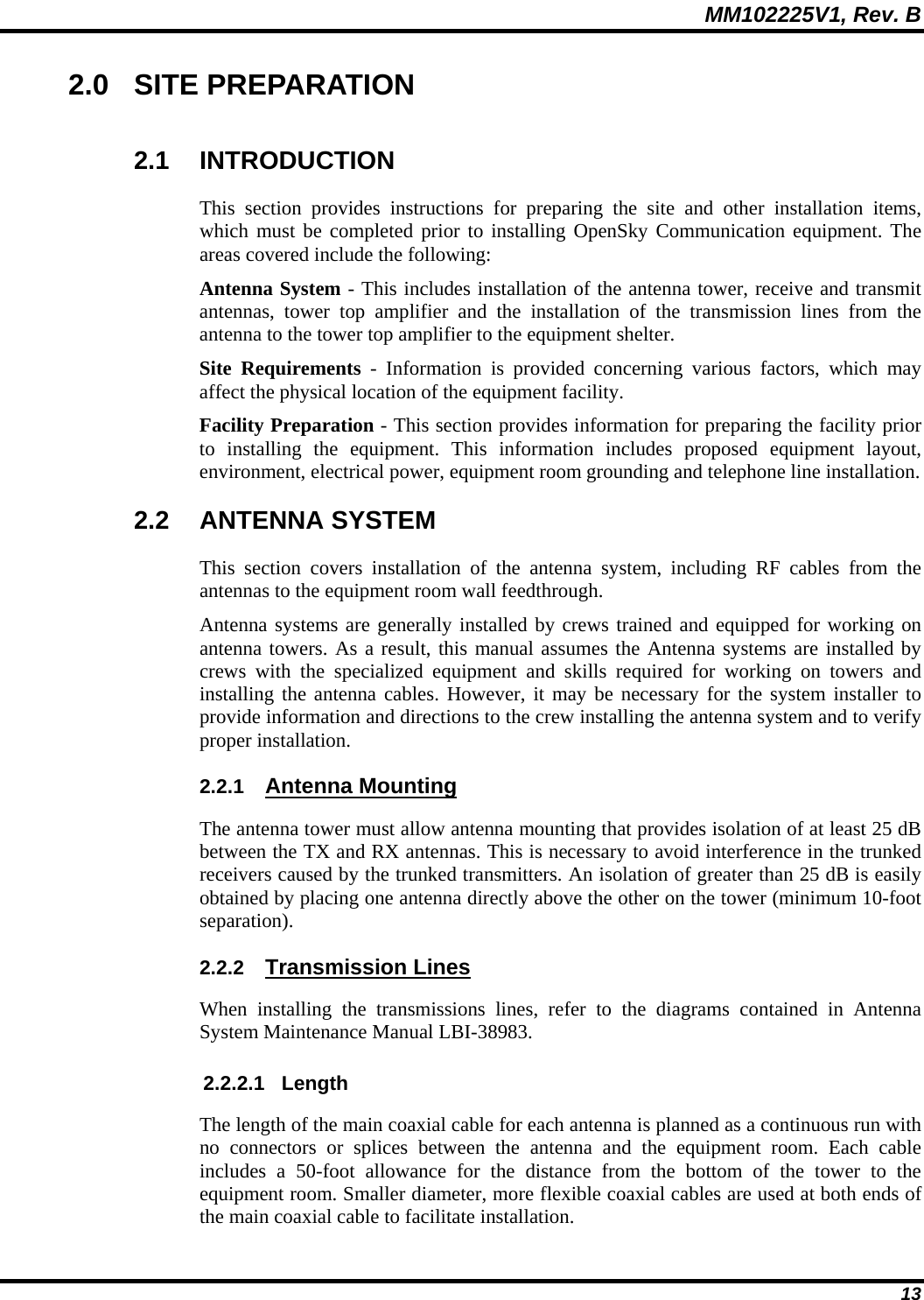
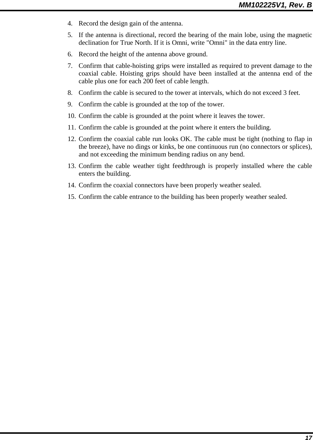
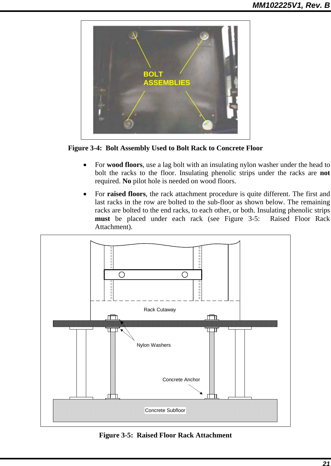
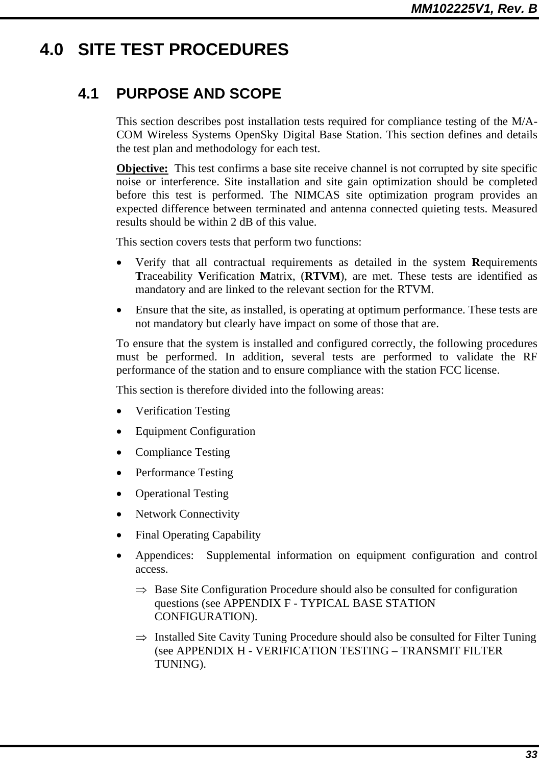
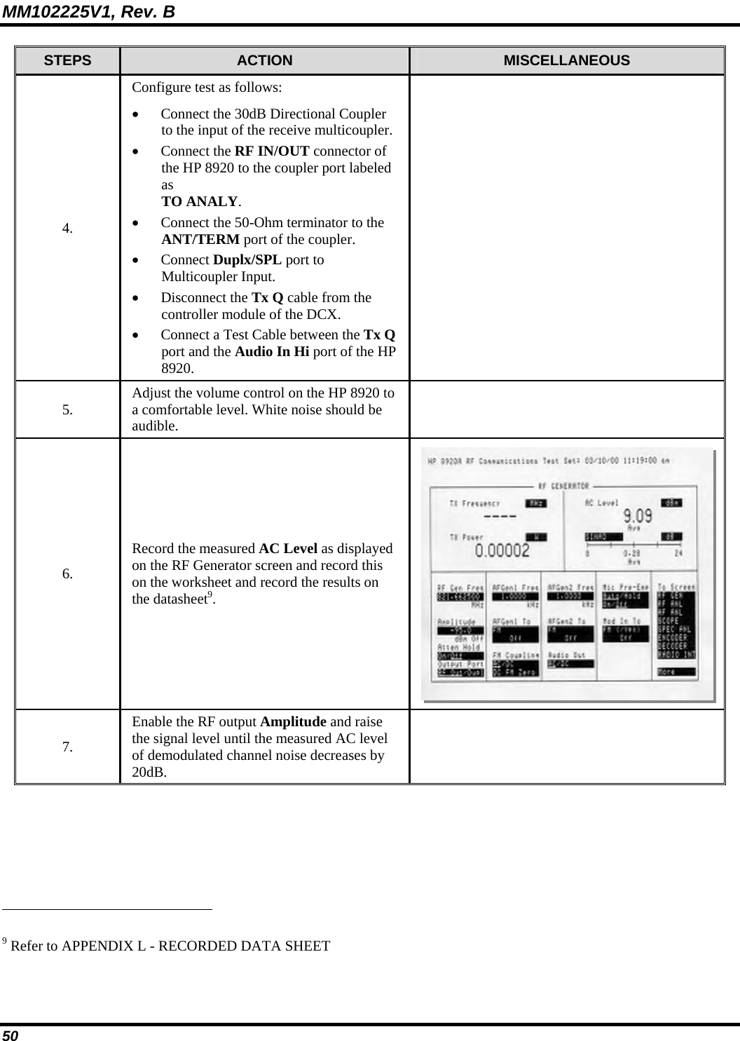
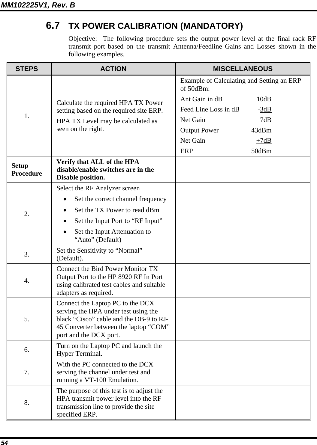
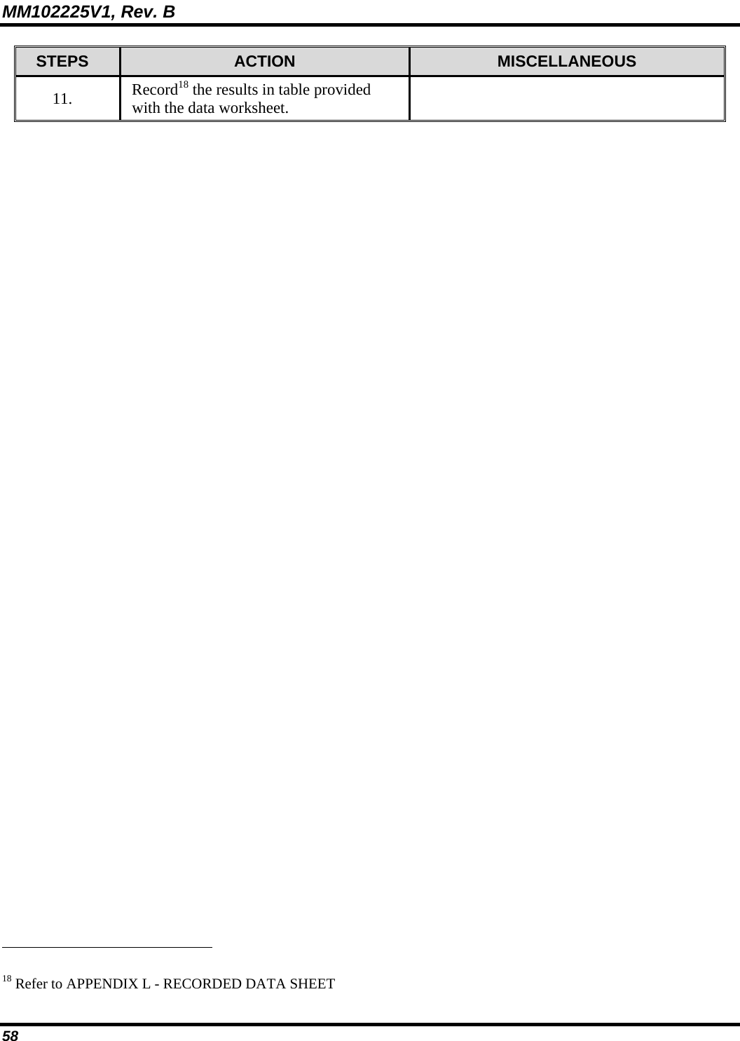
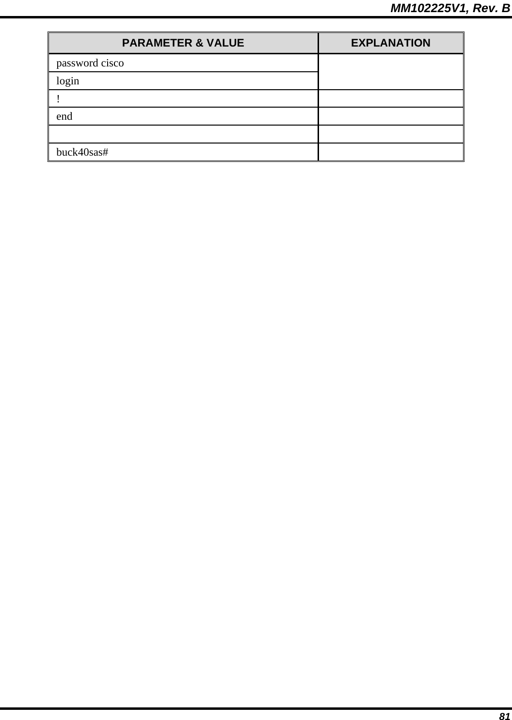
![MM102225V1, Rev. B 64 7.4.1 Power Failure STEPS ACTION MISCELLANEOUS 1. Connect the PC to the TERMINAL port of the DCX. 2. Type the command: opred ? [CR] 3. The DCX will respond with the information on the right. Manadabs2> opred? OPRED: BssN Status: Socket: 7 MCAddr: 225.1.2.35[6801] Cond: 1 OPRED: SasN Status: Socket: 8 MCAddr: 225.1.1.32[6802] Cond: 1 OPRED: Device Status: BSC:Up HPA:Keyed BSX:Up BSIB:Undef OPRED: Expected/Actual Peers - Normal: 1/1 Standbys: 0/0 MCD: 2 OPRED: Operating State: Normal Mode: 0x3e Does Standby: 0 OPRED: SCI CHN CDS BSC HPA BSX BSS_Address SAS_Address Reach OPRED: 2 2 68 Up Keyed Up 172.18.16.168 172.18.112.202 0xb OPRED: 1 1 68 Up Keyed Up 172.18.16.167 172.18.112.201 0xb OPRED: ------- OPRED: OK 4. Verify that the items shown in bold are indicated. 5. Turn off all circuit breakers feeding both racks of equipment. 6. Wait for 30 seconds before reverting all breakers to the ON position. 7. Verify that all equipment powers up. 8. Verify MES registration. 9. Repeat Steps 2 and 3 to verify the data once more.](https://usermanual.wiki/HARRIS/MBS800B075/User-Guide-964953-Page-65.png)
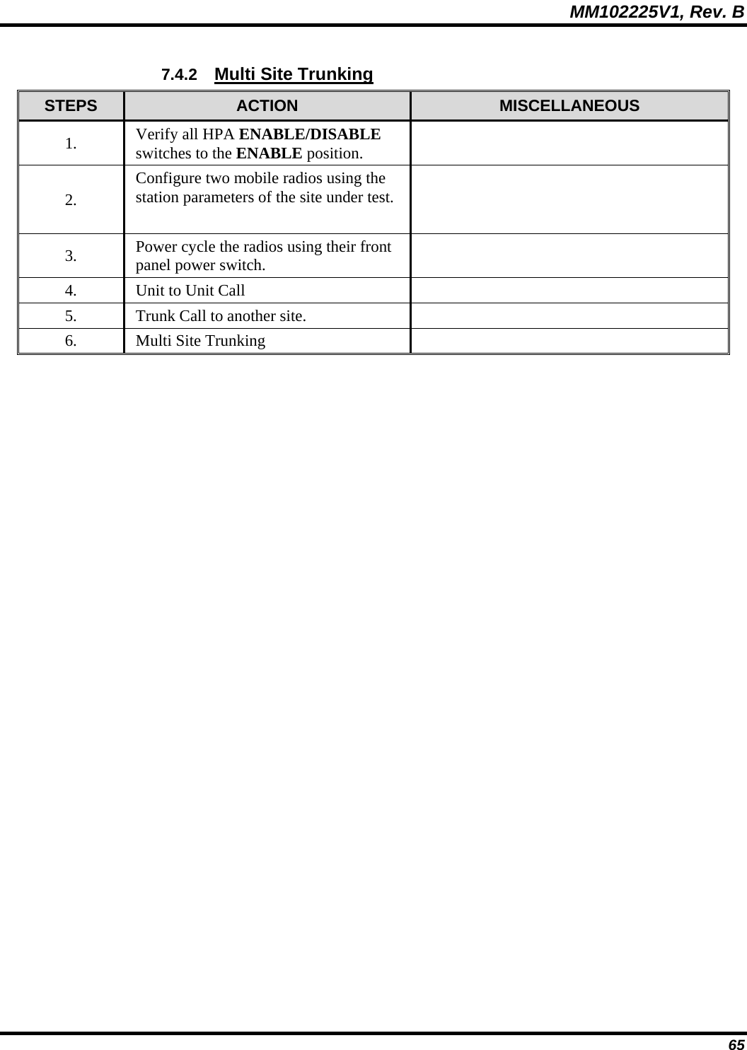


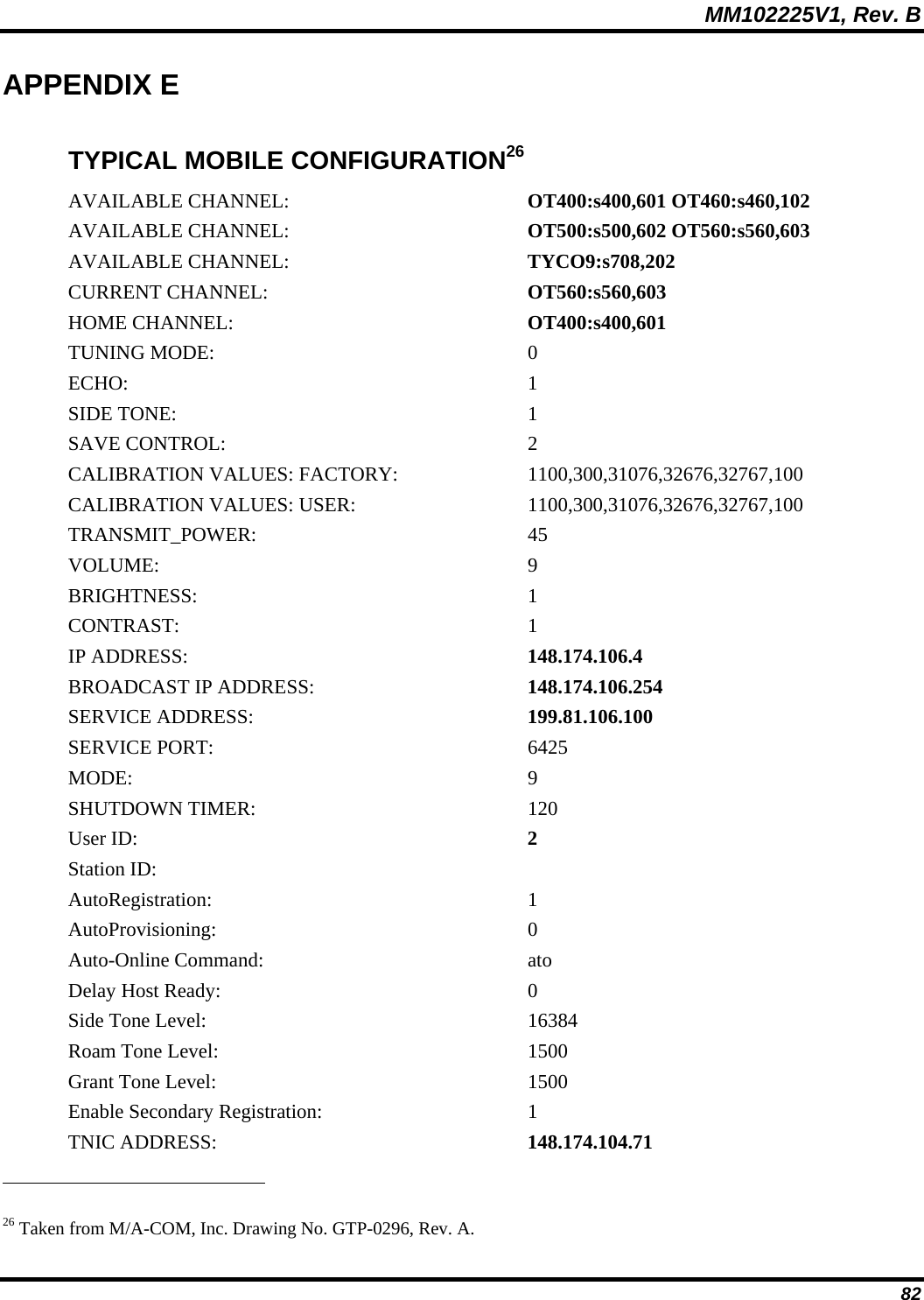
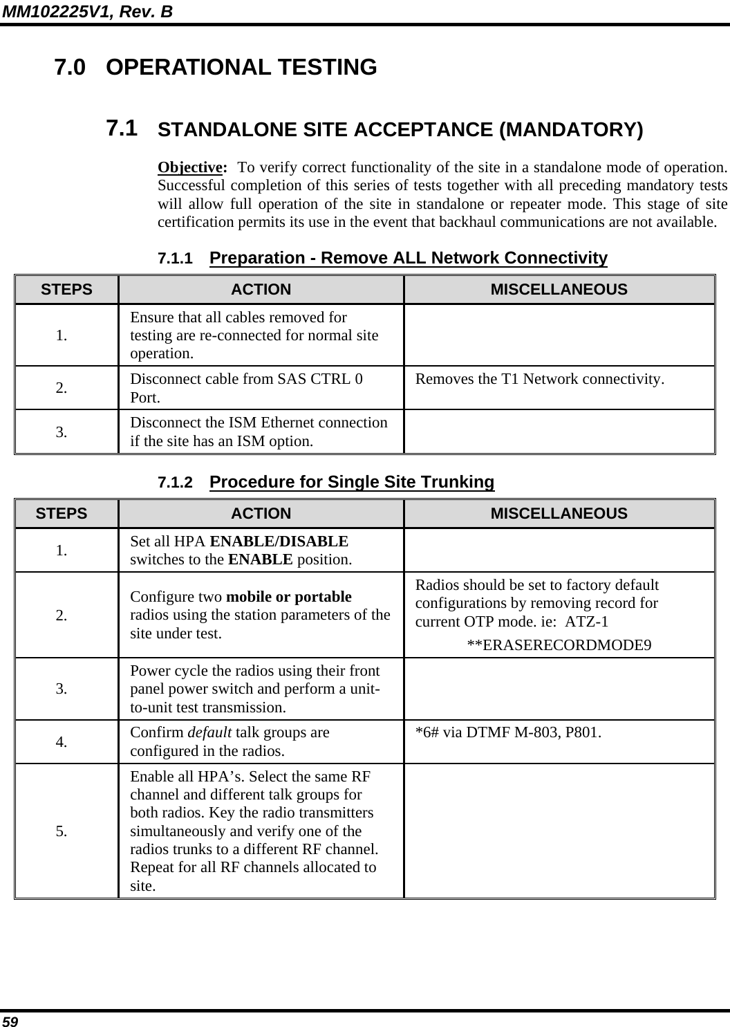
![MM102225V1, Rev. B 84 APPENDIX F TYPICAL BASE STATION CONFIGURATION27 manadabs2> at&v BSC INFORMATION: S/N: 000000010005 BSC INFORMATION: BSC S/W Version: BSC-1000 Version OTP 4.00 Sep 28 1999 14:58:02 BSC INFORMATION: BSC H/W Version: 50 MHz NGP Rev B with 1M of Memory BSC INFORMATION: M/A-COM HPA Version: 0.01e BSC INFORMATION: M/A-COM HPA Product String: 13-09-99 (0x01, 0x02) BSC INFORMATION: M/A-COM HPA Serial Number: 00000101 BSC INFORMATION: MACOM BSX Version: 802: 19 09/03/99 BSC INFORMATION: MACOM BSX Serial Number: 000000010004 Switch to Another Process: BSC I/P Address: 172.18.16.168 MDIS I/P Address: 172.18.16.200 MDIS PORT: 16962[4242] Voice Grant Timeout: 0[0] Null Voice Frame Limit (missed end): 15[f] Null Voice Frame Limit (after grant): 15[f] Null Voice Frame Limit (after trunk): 20[14] MSF Pause Interval: 3600[e10] MSF Pause Duration: 0[0] Set Channel Characteristics: MANA2[0 698]: Col:[1 4]/4/2 402 2 0 (0.0000,0.0000) Change Slip Interface Rate: 38400[9600] RSSI Hysteresis Value: 8[8] RSSI Scan Time: 90[5a] RSSI Scan Delta: 8[8] RSSI Average Time: 5[5] BLER Threshold: 10[a] BLER Average Time: 5[5] CBLER Threshold: 20[14] CBLER Average Time: 10[a] RRM CSI Epoch: 60[3c] 27 Taken from M/A-COM, Inc. Drawing No. GTP-0296, Rev. A.](https://usermanual.wiki/HARRIS/MBS800B075/User-Guide-964953-Page-85.png)
![MM102225V1, Rev. B 85 RRM Cell Configuration Epoch: 30[1e] RRM Quality Parameters Epoch: 120[78] RRM RC Roaming Epoch: 10[a] RRM RC Roaming Parameters: 80[50] 40[28] 2[2] 25[19] 10[a] RRM RC Utilization Epoch: 0[0] RRM Utilization Roaming Parameters: 10[a] 40[28] 0[0] 60[3c] 30[1e] RRM Deactivation Roaming Parameters: 4[4] NMS Port: 6100[17d4] Deviation Scale Factor: 1.000 Output Mode: 1[1] I/Q Max Deviation: 4000[fa0] I/Q Offsets: 70[46] -130[ffffff7e] I/Q Vector: 32767[7fff] 32067[7d43] 32767[7fff] 0[0] I/Q Amplitude: 16384[4000] BSC TYPE: 2[2] BSX oven oscillator warm-up time: 5[5] RPS I/P Address: 0.0.0.0 RPS PORT: 6222[184e] Tracking Receive (net->bs) PORT: 6667[1a0b] HPA Power Level: 44.900 [Current: 44.800] Reset RRM Parameters to Defaults: Show Adjacent Channels: MANA1[0 794]: Col:[1 4]/4/1 401 2 0 (0.0000,0.0000) Add Adjacent Channel: Remove All Adjacent Channels: Remove Specific Adjacent Channels: TNIC I/P Address: 172.18.16.200 TNIC Receive/Send PORT: 5762[1682] OpenSky NMS Port: 6102[17d6] Define NMS Trap Target: 0: 172.18.16.205,4000,0xffff Define NMS Trap Target: 1: 0.0.0.0,0,0xffff Define NMS Trap Target: 2: 0.0.0.0,0,0xffff Define NMS Trap Target: 3: 0.0.0.0,0,0xffff Define NMS Trap Target: 4: 0.0.0.0,0,0xffff Set NMS Operating Mode: 62 [0x3e] BSC Local Network I/P Address: 172.18.112.202 BSC Local Network Netmask: 255.255.240.0](https://usermanual.wiki/HARRIS/MBS800B075/User-Guide-964953-Page-86.png)
![MM102225V1, Rev. B 86 Dispatch Network Netmask: 255.255.240.0 Peer Port: 6800[1a90] Redundancy SAS Multicast Address: 225.1.1.32 Redundancy SAS Multicast Port: 6802[1a92] Redundancy BSS Multicast Address: 225.1.2.35 Redundancy BSS Multicast Port: 6801[1a91] Redundancy Peers: 1[1] Redundancy Standbys: 0[0] Redundancy Peer Heartbeat Timeout: 10[a] Redundancy Peer Query Timeout: 5[5] Redundancy Discovery Timeout: 90[5a] Redundancy Device Query Timeout: 10[a] Channel ID: 2[2] Site Component ID: 2[2] BSC Does Standby: 0[0] Both network links fail option: 0[0] Terminal prompt: manadabs2> Over the network download port: 6425[1919] Private Voice Group Boundary: 2000 Emergency Priority Boundary: 4 Default Voice Group info: private VG PRI:14, HT:0 sec. public VG PRI:16, HT:0. Voice Group Delete: Voice Group Add: 0: 101 2 30 Voice Group Add: 1: 102 4 30 Voice Group Add: 2: 201 6 10 Voice Group Add: 3: 301 6 0 Voice Group Add 4: 302 6 0 Voice Group Add: 5: 303 6 0 Voice Group Add: 6: 304 6 0 Voice Group Add: 7: 305 6 0 Voice Group Add: 8: 401 8 0 Voice Group Add: 9: 402 8 0 Voice Group Add: 10: 403 8 0 Voice Group Add: 11: 404 8 0 Voice Group Add: 12: 405 8 0 Voice Group Add: 13: 501 10 0 Voice Group Add: 14: 502 10 0 Voice Group Add: 15: 503 10 0](https://usermanual.wiki/HARRIS/MBS800B075/User-Guide-964953-Page-87.png)
![MM102225V1, Rev. B 87 Voice Group Add: 16: 504 10 0 Voice Group Add: 17: 505 10 0 BSIB is present: 0[0] BSIB should key: 0[0] ** NOT USED **: 0[0] BSIB VSWR Alarm Levels: 0.000 1.200 0.000 0.000 0.000 1.200 BSIB power Alarm Levels: 0.000 0.000 0.000 0.000 0.000 0.000 RX I/F Eq Tap: 7000[1b58] Dataflow Mark: 60[3c] Redundancy disable: 0[0] MAC continuity sum: 15[f] VERBOSITY : 1[1] OK](https://usermanual.wiki/HARRIS/MBS800B075/User-Guide-964953-Page-88.png)
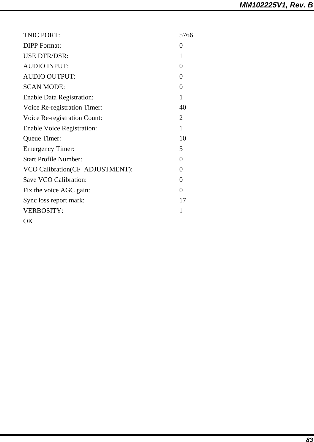
![MM102225V1, Rev. B 88 APPENDIX G TVARB STATUS28 TVARB show the status of the Transmit Voice Channel ARBitration (TVARB) process. Returned parameters provide useful insight to voice channel access information allowing system problems to be readily diagnosed. manadabs2> tvarbstate ************************************************************* num BSCs this site: 2 snooping: OFF bsc_info[0]= sci:2 chid:2 free_rev:2 free_fwd:2 bsc_info[1]= sci:1 chid:1 free_rev:2 free_fwd:2 free_rev_slots_site: 4 free_fwd_slots_site: 4 ************************************************************* OK manadabs2> tvarbvg2 ************************************************************* current number of queued requests: 0 max. number of queued requests: 0 state->next_rev_res_ctl entries: 0 state->new_tams_ctl entries: 0 state->active_tams_ctl entries: 0 state->deleted_tams_ctl entries: 0 bsc[0] {chnid:2 nports:2 free_fwd:2 free_rev:2} bsc[1] {chnid:1 nports:2 free_fwd:2 free_rev:2} TVARB: current calls: private_public_group_boundary: 2000 emergency_priority_boundary: 4 default PRIVATE_VG priority: 14 default PRIVATE_VG hang time: 0 sec. default PUBLIC_VG priority: 16 default PUBLIC_VG hang time: 0 sec. maximum_grant_time: 0 sec. ************************************************************* OK Test Cables: 28 Taken from M/A-COM, Inc. Drawing No. GTP-0296, Rev. A.](https://usermanual.wiki/HARRIS/MBS800B075/User-Guide-964953-Page-89.png)