HARRIS VMXBA VIDAMAX Base Station User Manual Part 90
Harris Corporation VIDAMAX Base Station Part 90
UserManual.wiki
>
HARRIS
>
VMXBA User Manual
Manual
Navigation menu
Upload a User Manual
Namespaces
Wiki Guide
HTML
PDF
Info
Views
User Manual
Discussion / Help
Navigation


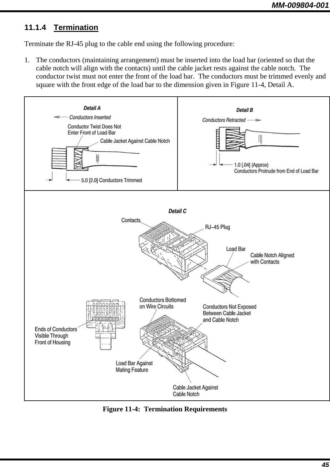
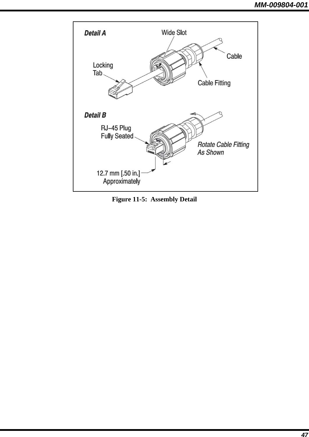
![MM-009804-001 2. The conductors must be retracted from the load bar so that the conductors protrude from the end of the load bar to the dimension given in Figure 11-4, Detail B. The top of the load bar must not be deformed. If the load bar is deformed, the conductor twist entered the front of the load bar 3. The load bar (oriented so that the cable notch is aligned with the contacts) must be inserted into the RJ-45 plug until it butts against the mating feature of the RJ-45 plug, and the conductors are bottomed on the wire circuits. The cable jacket must be against the cable notch after the load bar is fully seated. The conductors must not be exposed between the cable jacket and cable notch. The ends of the conductors must be clearly visible through the front of the RJ-45 plug. See Figure 11-4, Detail C. If the conductors do not bottom on the wire circuits, they must be re-trimmed (after removing the load bar/cable assembly from the RJ-45 plug), and re-inserted into the RJ-45 plug. If the conductors are too short, the cable must be re-stripped. 4. The RJ-45 plug must be terminated to the cable according to the instructions included with the tooling. 11.1.5 Assembly Assemble the RJ-45 connector into the plug assembly using the following procedures: 1. Align the locking tab of the RJ-45 plug with the wide slot at the front (end opposite the cable fitting) of the plug assembly. See Figure 11-5, Detail A. 2. Depress the locking tab, and insert the RJ-45 plug into the plug assembly. Gently pull the cable until the RJ-45 plug is fully seated. There should be approximately 12.7 mm [.50 in.] of the RJ-45 plug protruding from the front of the plug assembly. See Figure 11-5, Detail B. CAUTION To avoid damage to the connection, the cable must be pulled GENTLY when seating the RJ-45 plug. 3. While holding the RJ-45 plug in position, rotate the cable fitting as shown in Figure 11-5, Detail B until tightened to a torque of 1.13 N–m [10 lbf–in.]. The given torque must be met in order for the cable fitting to seal the plug at the cable end. 46](https://usermanual.wiki/HARRIS/VMXBA/User-Guide-686497-Page-47.png)