Harvest One WFTV6II Cactus Wireless Flash Transceiver V6 II User Manual V6II
Harvest One Limited Cactus Wireless Flash Transceiver V6 II V6II
UserManual.wiki
>
Harvest One
>
WFTV6II User Manual
User manual
Navigation menu
Upload a User Manual
Namespaces
Wiki Guide
HTML
PDF
Info
Views
User Manual
Discussion / Help
Navigation
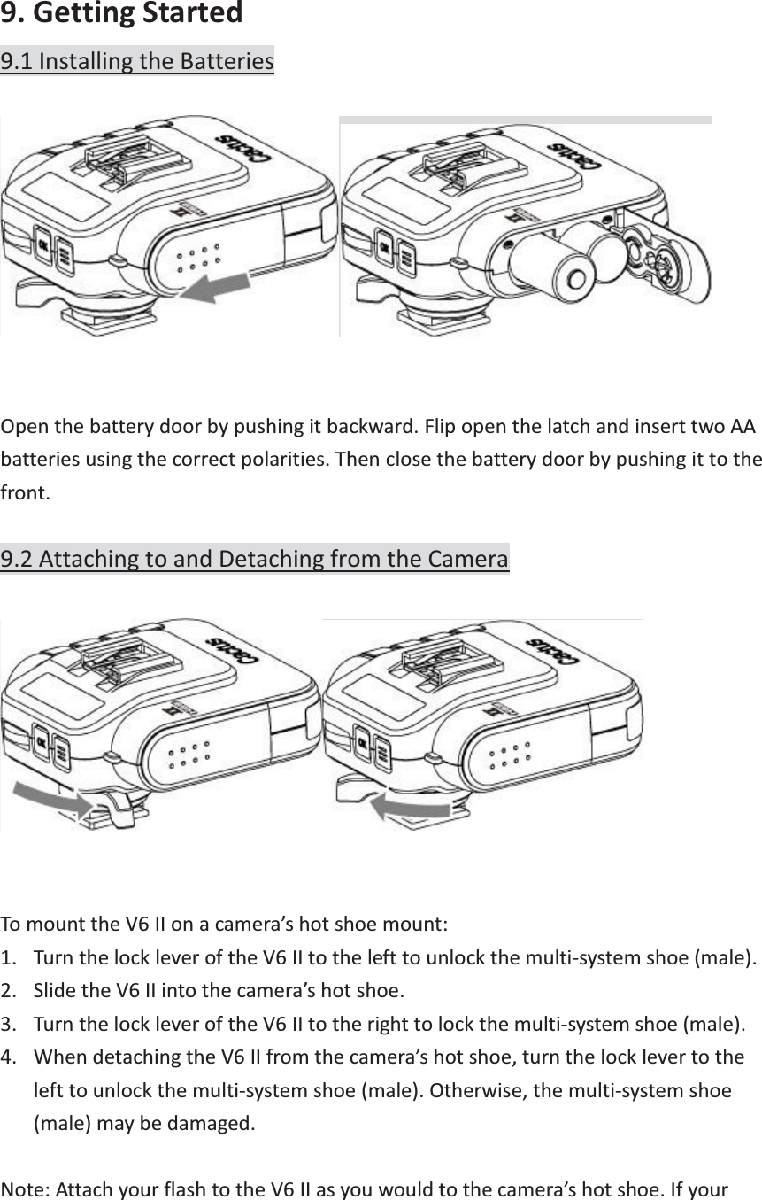
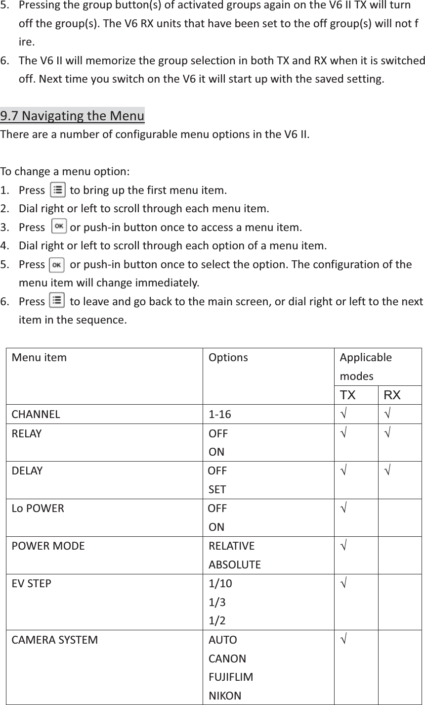
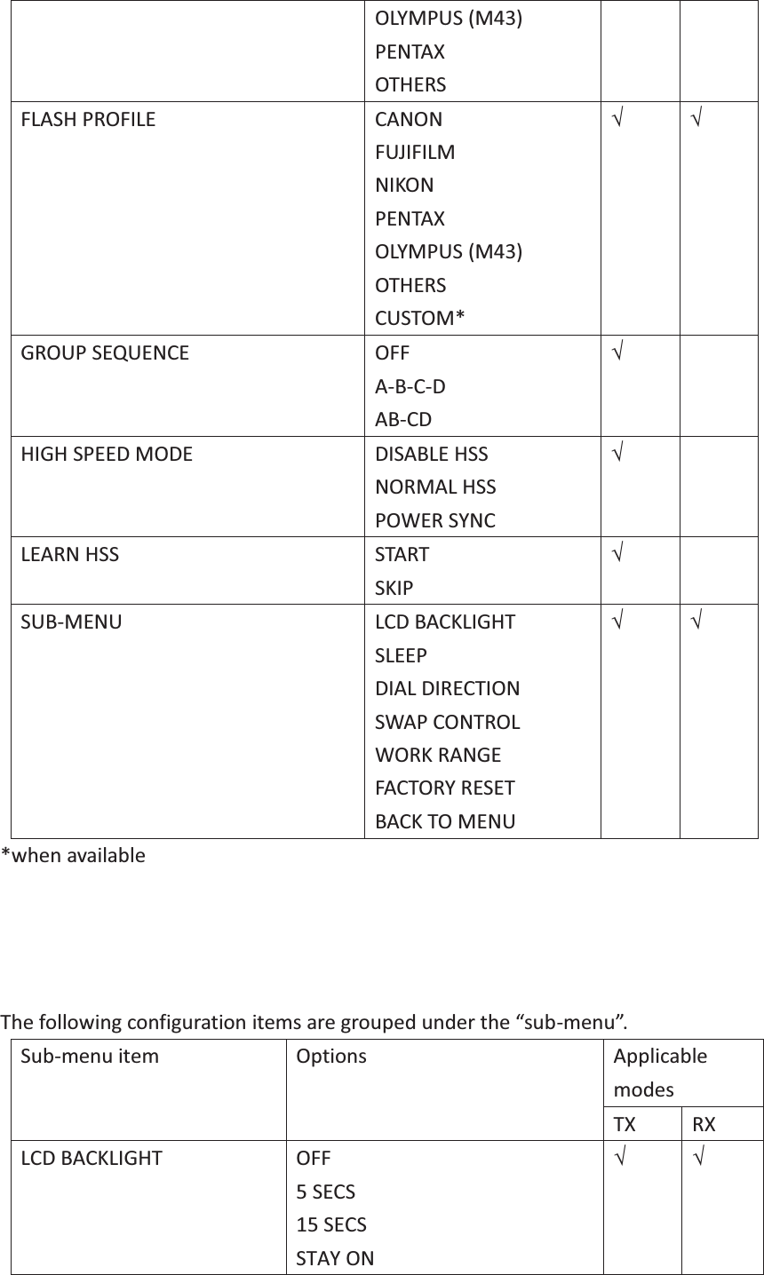
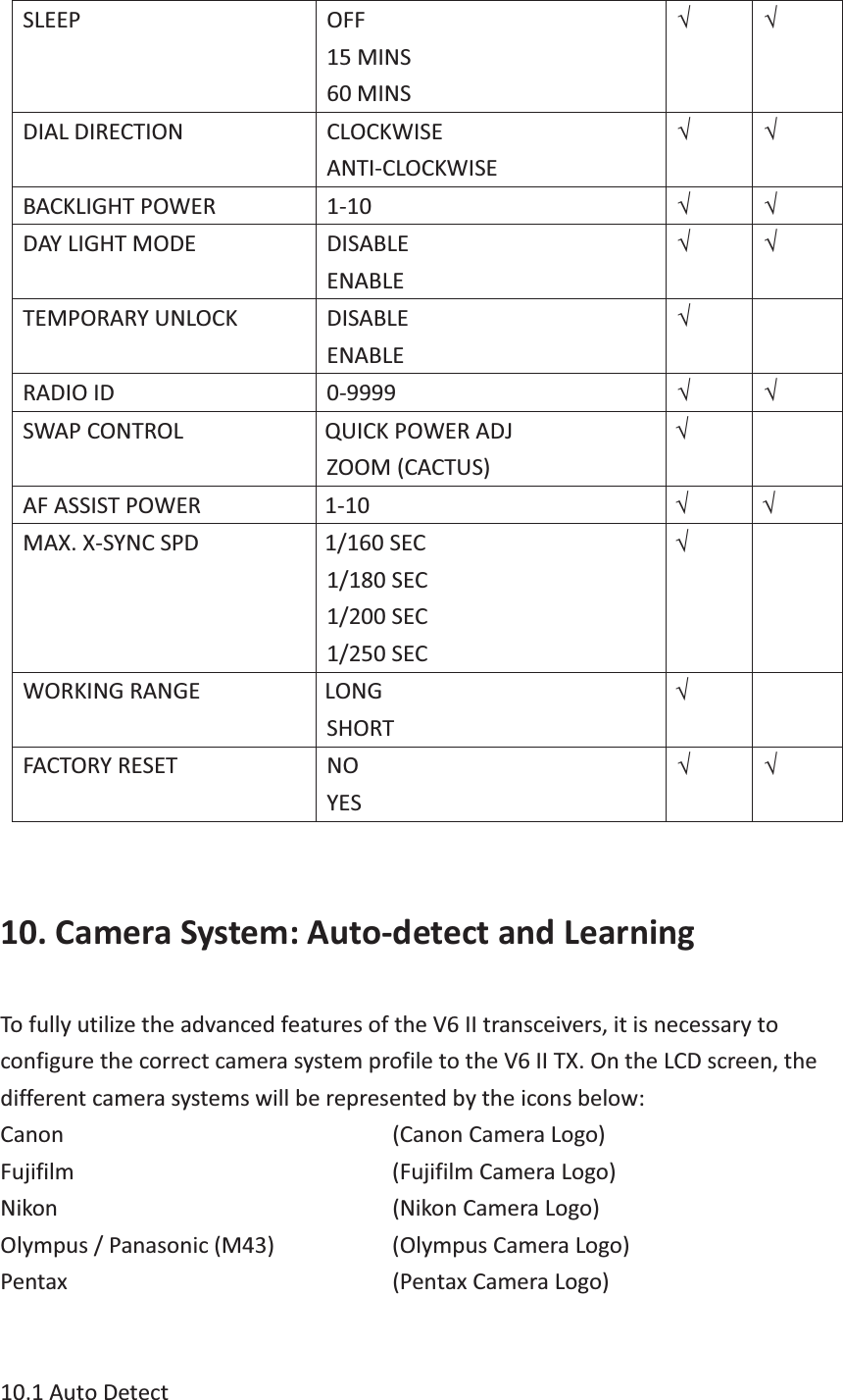
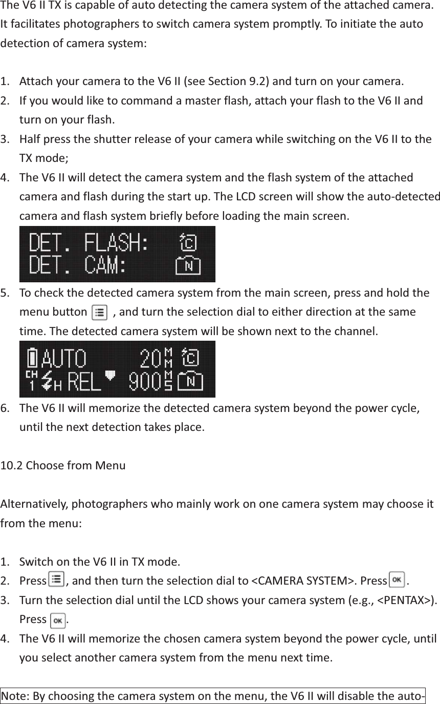
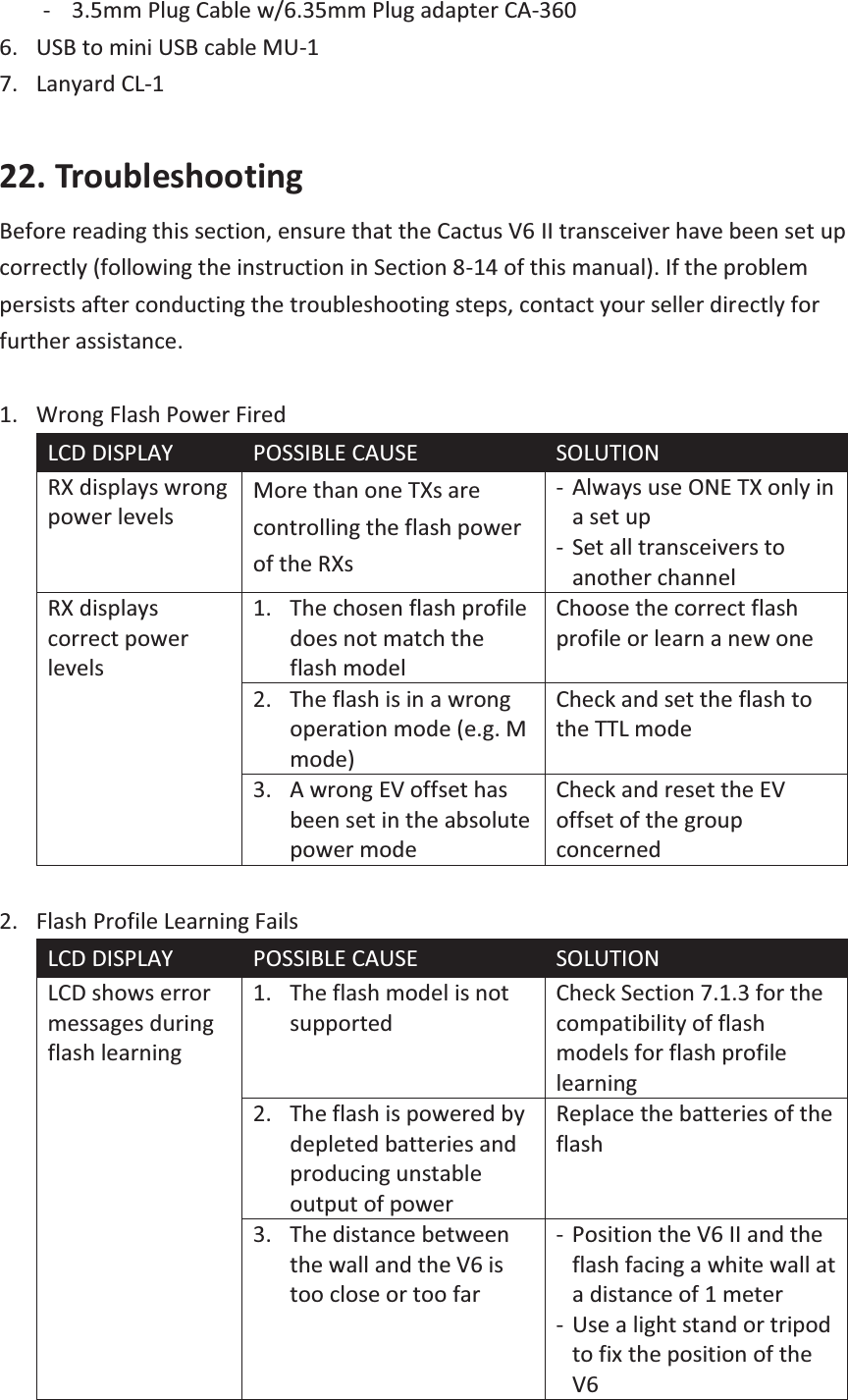
![In <DIAL DIRECTION>, the selection dial of the V6 can be configured to operate in a <CLOCKWISE> or <ANTI-CLOCKWISE> direction. To increase the power level in the main screen, for example, you would have to turn the selection dial to the left in the clockwise setting, or turn it to the right in the anti(counter)-clockwise setting. 17.2 Selection Dial Lock To prevent unintended turning of the selection dial and its consequence of affecting the power levels, the dial can be locked in the main screen of the TX mode: 1. To lock the selection dial, press and hold the selection dial or for 2 seconds. The LCD will show [lock] at the left upper corner. 2. To temporarily unlock the selection dial, press the selection dial or once. Alternatively, press and hold any group button to select a group for power level adjustment. The LCD will show [unlock] to indicate the temporary unlock status. The dial will be locked again when no button or dial is pressed or turned in 2 seconds. 3. The temporary unlock mechanism can be enabled or disabled in the <TEMPORARY UNLOCK> sub-menu. 4. To permanently unlock the selection dial, press and hold the selection dial or for 2 seconds. Note: The short-cut for adjusting the power level of a single group by pressing a group button and turning the dial simultaneously (see Section 12.1.1) will be unaffected. 17.3 Swap Control In the main screen of the V6 II TX, pressing or the push-in selection dial once will change it to one of the following modes: yQuick Power Adjustment Mode <QUICK POWER ADJ>: expanding the power adjustment to 1EV step (see Section 12.1.3). yZoom (Cactus) Mode <ZOOM (CACTUS)>: controlling the zoom level of the Cactus RF60 (see Section 16.1.1). This can be conf igured in <SWAP CONTROL>. 17.4 LCD Options The LCD screen of the V6 II can be configured in the following ways:](https://usermanual.wiki/Harvest-One/WFTV6II/User-Guide-2991288-Page-33.png)