Hasselblad 503 Cw Service Manual Omslag
Hasselblad-503-Series-10026-Users-Manual-564123 hasselblad-503-series-10026-users-manual-564123
10026 to the manual 1d49879d-7519-47a5-89e6-6f7bbcad0a6d
503 CW - Service Manual 500-503_sm_en Free User Guide for Hasselblad Camera, Manual
2015-07-27
: Hasselblad Hasselblad-503-Cw-Service-Manual-775197 hasselblad-503-cw-service-manual-775197 hasselblad pdf
Open the PDF directly: View PDF ![]() .
.
Page Count: 93
- Back to start
- Service Manual 503CW Cover
- Contents list
- Related Service Infos
- 1. General description
- 2. Tools
- 3. Disassembly
- 4. Reassembly
- 5. Adjustment
- 6. Sub-assembly
- 7-19. Exploded Views and Spare Part lists
- 7. Shell
- 8. Gear housing
- 9. Mechanism plate
- 10. Auxillary shutter and mirror assembly
- 11. Front bayonet plate
- 12. Right hand wall
- 13. Left hand wall and electronics
- 14. Winding crank
- 15. Camera body - 501C
- 16. Camera body - 503CXi
- 17. Camera body - 503CX
- 18. Camera body - 500C/M (Classic)
- 19. Camera body - 501CM
503CWOMS.EPS
960807
COPYRIGHT © 1996 ANDERS ENGSTRÖM
ANDERS ENGSTRÖM, ILLUSTRATÖR
Östra vägen 46
430 91 HÖNÖ
tel/fax 031- 96 84 64
anders@aeillustr.se
Victor Hasselblad AB
Göteborg Sweden
Service Manual
Copyright © 1998 by Victor Hasselblad AB. All rights reserved. No parts of this material may be reproduced, stored
in retrieval system or transmitted, in any form or by any means, electronic, mechanical, photocopy, recording, or
otherwise, without the prior written permission of the Company.
October 1996

1.
2.
3.
4.
5.
6.
7.
8.
9.
10.
11.
12.
13.
14.
15.
16.
17.
18.
19.
Camera body 503CW
Contents list
Revision 1 May 1997
General
Camera body 501C
Camera body 503CXi
Camera body 503CX
Camera body 500C/M (Classic)
Exploded view: Winding crank
Exploded view: Left hand wall and electronics
Exploded view: Right hand wall
Exploded view: Front bayonet plate
Exploded view: Auxiliary shutter and mirror assembly
Exploded view: Mechanism plate
Exploded view: Gear housing
Exploded view: Shell
Sub-assembly: Front bayonet plate and auxiliary shutter with mirror
Adjustment, final assembly and calibration of the flash meter
Reassembly
Disassembly
Tools
Camera body 501CM

Related Service Infos
Revision 4 January 2001
503CW - 501C - 503CX/CXi - 500C/M - 501CM
20/93 Flash metering circuit redesigned - 503CX
04/94 New camera - 501C
05/94 Exploded views and spare part specifications - 501C and 503CXi
06/94 Spare part No. changed - 500C/M and 503CX
12/94 Pin fitted in bayonet plate - 501C
04/95 Tripod foot modified - 501C and 503CXi
09/95 New tool - 503CXi
10/95 Updated pages - 503CXi
02/96 Signal arm shortened - 501C and 503CXi
14/96 New Service Manual - 503CW
14/97 New camera body - 501CM
15/97 Modifications - 501C and 503CW
28/97 Camera body in black finish - 501CM
12/98 New film speed range - 503CW
02/99
10/99 Discontinued parts - 501C, 503CXi, 503CX and 500C/M
Stray-light - 503CW, 501CM, 501C, 503CX/CXi and 500C/M
08/00
New CD-ROM - Version 1.3
09/00 Washer added in the gear box - 501CM and 503CW
01/00 New CD-ROM - Version 1.2
14/00 Discontinued parts - 500 series cameras
12/96 Tripod foot adapter/kits
17/93 Fitted with wrong spacers - 503C/M and 503CX
01/01 Modified magazine hook - 501CM and 503CW
1.

Related Service Infos
Revision 4 January 2001
503CW - 501C - 503CX/CXi - 500C/M - 501CM 2.
New CD-ROM - Version 2.0
04/01

June 1998
Camera body 503CW General description
1:1
Revision 1
Camera type: Single lens reflex camera with 6 x 6 (2 1/4 x 2 1/4 in) max.
film size. Interchangeable lenses, film magazines, viewfinders
and focusing screens.
Weight: 610 g.
Lens mount: Hasselblad bayonet mount for CF and C lenses.
External
dimensions: 91L x 114W x 110H (3 9/16 x 4 1/2 x 4 11/32 in).
*Acute-Matte D designed by Minolta
Design: Mechanical, with an aluminium alloy camera body shell cast in
one piece.
Viewfinders: Folding focusing hood interchangeable with reflex viewfinder,
prism viewfinders with or without built-in exposure meter or
magnifying hoods.
Film advance: Manual advance or motor driven with Winder CW.
Simultaneous shutter cocking.
Winder CW winding time: 1.05 sec, approx. 0.8 frames/sec
in continuous mode.
Flash control: TTL/OTF-metering. ISO 16 - 1000 with flash adaptors
SCA390 or SCA590 for connection with flash units from the
SCA300 or SCA500 systems respectively. Metering area within
40 mm diameter in the centre of the image area.
Note! From camera serial No. 19ER18271 the ISO range is
changed to 64 - 4000.
Tripod coupling: 1/4 in and 3/8 in socket threads and base plate for quick
coupling attachments.
Focusing screen: Hasselblad Acute-Matte D* focusing screen.
Sales code No. 42204.

0 319°
300
280
260
240
220
200
180
160
140
120
100
80
60
40
20
0
20
40
60
80
100
120
140
160
180
200
220
240
260
280
300
320
340
360°
503DGRM1
961018
COPYRIGHT © 1996 ANDERS ENGSTR
Ö
M
ANDERS ENGSTRÖM, ILLUSTRATÖR
Östra vägen 46
430 91 HÖNÖ
tel/fax 031- 96 84 64
anders@aeillustr.se
October 1996
1:2
Camera body 503CW Camera release sequence
April 1998
Revision 0
Release sequence
Pre-
released
position
Variable
timing
interval
Key
position
Mirror
Auxiliary
shutter
Lens shutter
Aperture f 2.8 f 22
1/500 sec

Tools
Camera body 503CW
October 1996
Revision 0
Tool No. Description Used for
2:1
V-2200 Bender Signal arm adjustment
V-2201 Bender Mirror arm adjustment
V-2202 Bender S-arm adjustment
V-2203 Bender Release arm adjustment (aux. shutter)
V-2205 Bender Supporting tool when using V-2201
V-2206 Winding knob Substitutes regular winding crank during
repair work
V-2211 Pin driver Fitting the locating pin in the front plate
and the front gear bracket
V-2224 Bender Release arm adjustment
V-2229 Focal length gauge Adjustment of the focal length,
mirror 45ºangle and focusing screen
V-2236 Microscope Focusing screen adjustment
V-2354 Exposure gauge Release sequence control
V-4151/52 Focusing tester Focusing screen adjustment
V-4704 Key Focusing screen adjustment
V-4705 Focusing screen adapter Focusing screen adjustment

Tools
Camera body 503CW
October 1996
Revision 0
Tool No. Description Used for
2:2
V-5423 Riveting jig Replacement of aux. shutter flaps
V-5942 Exp. gauge Release mechanism adjustment
902474 Test box ELX/CX Calibration of the TTL flash meter
902658 Key angle gauge Adjustment of the front key angle
(V-2075)
904644 Bayonet plate Stop lever adjustment
970600 Service Test System Calibration of the TTL flash meter
905020 Screwdriver Screws in the mirror box
January 2001
Camera body 503CW Disassembly
3:1
Revision 1
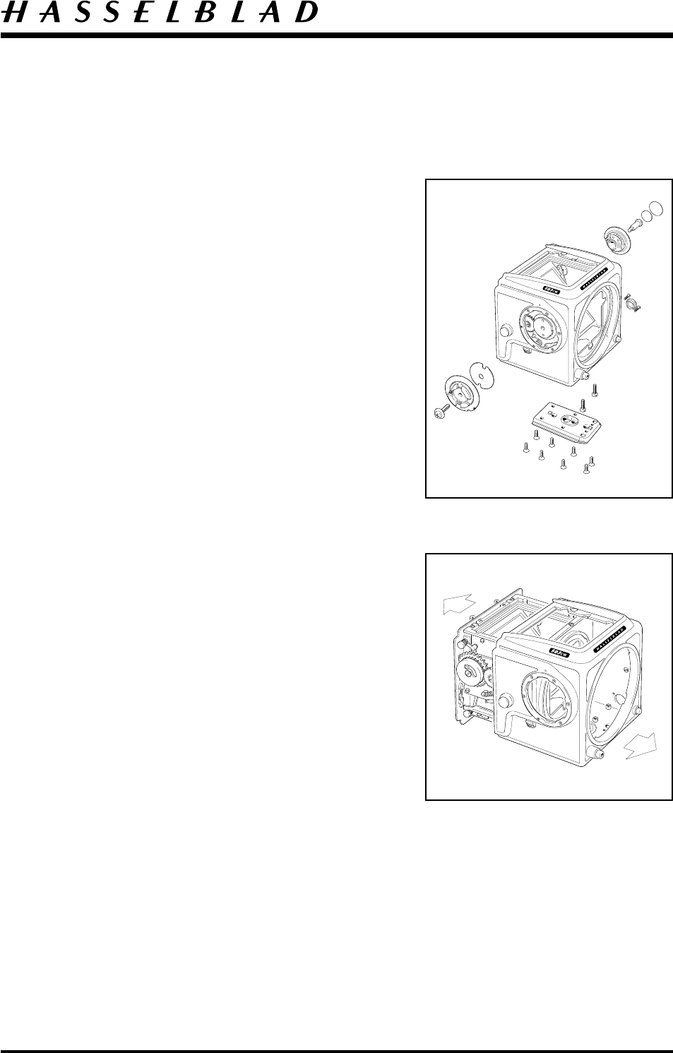
Camera shell
Remove the lens, film magazine, view finder, focusing
screen and winding knob.
Remove the screw (830060), coupling (22767) and
washer (22799).
Remove the leather (13374), shim (22473), screw
(822701) and ISO selector knob (22495).
Do not damage the sliding contacts.
Remove the cap (22470) from the chassis connector and
peel back the leather covering two screws
(823335). Remove these screws and firmly push the
chassis connector into the body of the camera.
Remove the tripod foot (30763) held by six screws
(829755). Remove the two rear screws (829755) and
the two front screws (820781).
Fig. 1.
The chassis can now be separated from the camera shell.
Ensure that the lens release button (13139), release
button (22759), buffer (22367), teflon cone (103773)
and distance washers (810620) are not dislodged from
the camera shell and lost.
Fig. 2.
Operate the S-release on the camera by pressing the
S-arm (21167) towards the stop. Remove the front gear
cover (22876). Do not remove the side cover (22813)
unless it is absolutely necessary.
The side cover is held in position by the spring (30775)
secured with two screws (829425) and double sided
tape.
Note! If removed, a new cover must be used when the
camera is reassembled.
Fig. 1
Fig. 2
May 2000
Camera body 503CW Disassembly
Revision 2
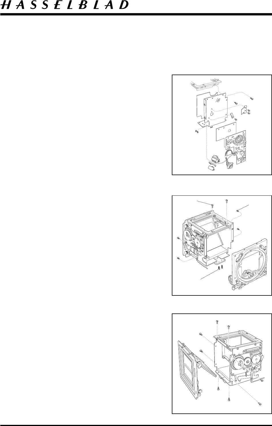
Circuit board (22575) *22882
CAUTION! When handling the circuit board a
grounded bench mat and a wrist strap must be
used to prevent ESD damage.
Lift the chassis connector out of the hole in which it is seated
in the left hand wall. Remove the two screws (820325) that
secure the photodiode. Gently ease the photodiode through
the hole in the left wall.
Remove the two screws (820011) and the grounding
attachment (22453). Remove the screw (820011) and the
cable holder (12453). Remove the two screws (820015) and
separate the circuit board from the chassis.
Finally, remove the insulating plate (22746).
* Note! The circuit board (22882) is fixed to the wall by an
insulating double-sided tape, screws and attachment.
Fig. 3.
Front bayonet plate (30777)
Disconnect the spring (814512) from the push rod (22369).
Remove the release bar (30375) by gently lifting it with a
screwdriver so that it is freed from the front gear wheel and
then easing it forward.
Remove the front bayonet plate (30777) by removing two
screws (820015) in each of the right and left sides, two
(821017) in the view finder screen frame and two (823655)
in the bottom plate. Carefully draw the front plate forward.
Fig. 4.
Note! The drive spring should be held when the gear wheel
is released to prevent damage to the drive spring by
releasing the tension too quickly.
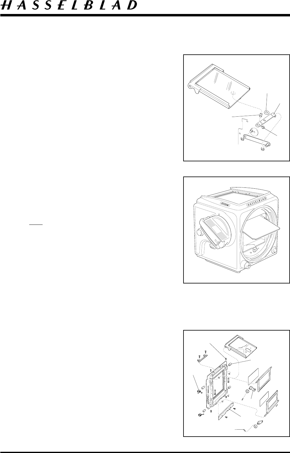
Rear plate (30300)
(including auxiliary shutter)
Disconnect the arm (22781) secured to the mirror frame by
a clip (817115). Remove the washer (810649) underneath
the arm. Remove two screws (821017) on top of the
focusing screen frame and six (820015) then partly withdraw
the rear plate. When partly removed, disconnect both the
upper and lower connecting rods. The rear plate can now be
removed completely.
Fig. 5.
3:2
Fig. 3
Fig. 4
Fig. 5
823655
820015
821017
Camera body 503CW Disassembly
October 1996Revision 0
3:3
Focusing screen frame (22812)
Remove the two remaining screws (820015) holding the
focusing screen frame to the right hand wall and lift the
frame off.
Right hand wall (21095-1)
Remove (or cut) the foam plastic pad (22582) to get
access to the three screws (820014). Remove the right
hand wall.
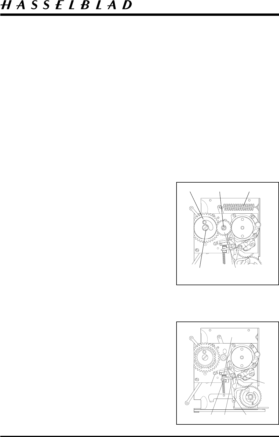
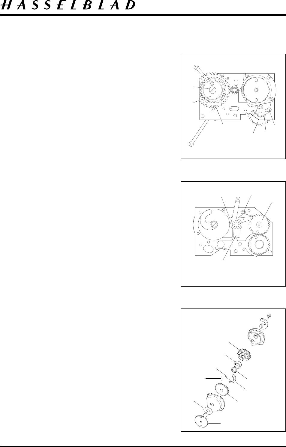
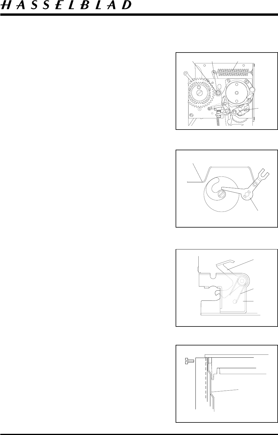
Mechanism plate (21125-1)
Remove the damping ring (22287) by first removing
screw (822605) and washer (810836). Put the screw
(822605) back, to keep the spring (30384) in place.
Remove the screw (821631), washer (810532) and gear
wheel (13112). Beneath the gear wheel remove washer
(810826). Remove the mirror spring (814827).
Fig. 6.
Remove the mirror actuating lever (13362) from the
rear of the right hand side wall together with the lens
lock (13280).
Remove the following parts shown in Fig. 7.
1. Spring (814826)
2. Screw (821032)
3. Spring (816914)
4. S-arm (21167) and hub (840701)
5. Release arm (13357) including push rod (22369)
6. Stop lever (22769), clip (817119) and spring
(816752)
Remove the remaining six screws, the stop angle
(13432) and adjustable pawl (13170).
Separate the mechanism plate from the right hand wall.
Fig. 7
3
6
1
425
Fig. 6
13112
822605
22287 821631 814827
DIS10.EPS
Camera body 503CW Disassembly
3:4
May 2000
Revision 1
Remove the lower (13101) and the upper (13100)
connecting rods and dismantle the remaining parts on
the mechanism in the following order.
Fig. 8.
1. Screws (820016) 2 pcs
2. Bearing bracket (13171) and nut (13116)
3. Gear wheel (13167)
4. Screw (822605)
5. Lid (14280)
6. Gear (22699)
Note!
When removing the gear (22699) care should be taken
to ensure that the spring (30384) does not become
displaced.
Reverse side.
Fig. 9.
10. Gear (13182)
11. Auxiliary shutter stop (22436)
12. Clip (817112) washer (810404) spring (816802)
13. Shutter bar (20912) (Note. The gear housing must
be rotated)
Gear housing (30324)
Remove the gear housing from the mechanism plate and
remove the screw (821033) and the cam (22355).
Separate the front and rear section of the gear housing
and disassemble as follows.
Fig. 10.
1. Disconnect spring (816504)
2. Remove activating hook (20919)
3. Locking ring (810938)
4. Washer (810826)
5. Locking pin (812106)
6. Gear wheel (13169)
7. Ratchet wheel (20924)
8. Washer (810840)
9. Gear wheel (13509)
Fig. 8
Fig. 9
Fig. 10
12
13
6
3
5
21
4
10
11
3
4
1
2
6
5
7
9
8
DIS10.EPS
Camera body 503CW Reassembly
May 2000Revision 1
4:1
The lubricants mentioned in the text are:
Grease = Isoflex Topas L32
Oil = Isoflex PDP 48
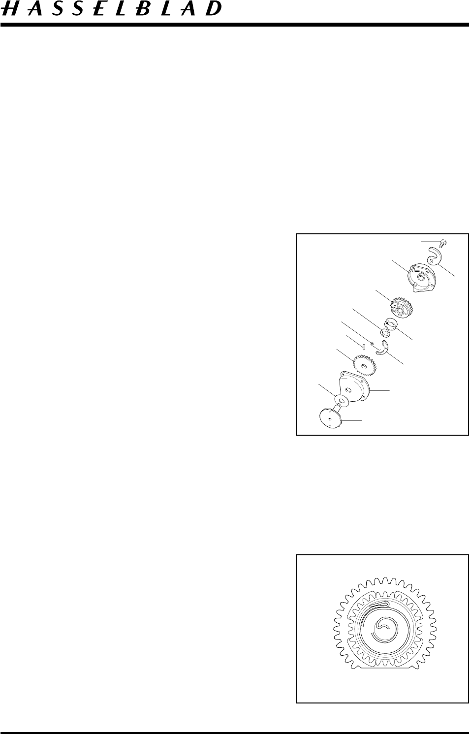
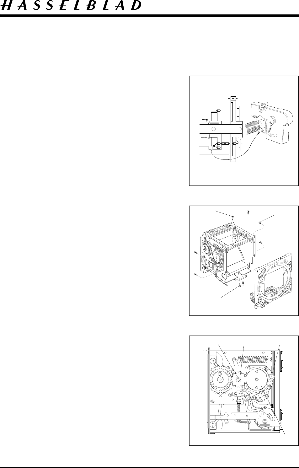
Gear housing (30324)
Lubricate carefully the washer (810840) with
oil. Lubricate with grease and fit (incl. the above
mentioned washer) the ratchet wheel (20924) into the
front section of the gear housing (30304).
Lubricate with grease and fit the gear wheel (13169).
Note. The correct relationship between the two gears
before inserting the locking pin (812106) into the shaft.
Fit the locking ring (810938) and the activating hook
(20919), lubricate carefully with oil. Fit the spring
(816504) and the washer (810826).
Place the stop gear (13509) into the rear section of the
gear housing (13157).
Lubricate the shaft of the ratchet wheel (20924) and
put the front and rear section together.
Fit the mirror cam (22355) and secure with the screw
(821033).
Note! The position of the mirror cam (22355) relative
to ratchet wheel (20924).
Fig.11.
Mechanism plate (21125-1)
Ensure the auxiliary shutter release connecting rod
coupling and the control gear wheel move freely (i.e.
with no friction). Lubricate lightly with oil. Lubricate
the gear wheel’s cam with grease.
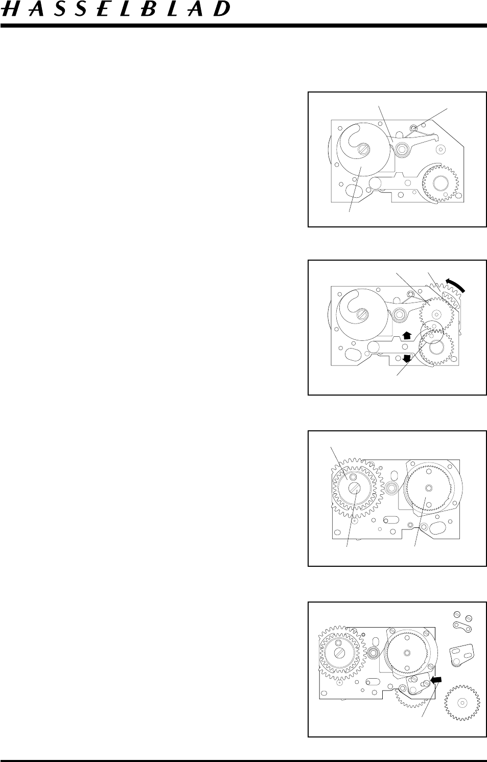
If it is necessary to replace the coil spring (30384) fit it
into the spring mounting on gear wheel (22699) as
shown in fig.12. Use a new spring, contained in its
plastic ring. Lubricate with grease.
20924
30304
810938
20919
812106
13169
816504
810826
13509
13157
22355
821033
Fig. 12
Fig. 11
810840
Camera body 503CW Reassembly
May 2000Revision 2
4:2
Fig. 13
Fig. 14
Fig. 15
Fig. 16
Gear alignment
13182 22699
14280
822605 Gear housing
13167
13171
13116
820016
Mount the gear housing (30324) to the mechanism
plate.
On the reverse side of the mechanism plate lubricate
the hub with grease and fit the shutter stop bar (20912)
spring (816802), washer (810404) and clip (817112).
Fig. 13.
Note! The gear housing must be rotated when fitting
the stop bar (20912).
Lubricate the cam of the gear wheel (13182) with
grease and fit to the mechanism plate.
Note! The position of the gear wheel engagement
according to fig.14.
Hold the gear wheels in position and on the reverse side
of the mechanism plate, position washer (810932) and
lubricate the hub with grease. Fit gear wheel (22699)
together with the coil spring. Lubricate the coil spring
with grease.
Assemble the lid (14280) and temporarily secure with
the screw (822605). Fig. 15.
Tension the spring by rotating the gear wheel (22699)
in the direction shown in fig. 14. Test the operation by
pushing the shutter release connecting rod up and down
several times (tension the spring after each operation).
The gear wheels should rotate freely. Fig. 14.
Lubricate with grease and fit the intermediate gear
wheel (13167), bearing bracket (13171), nut (13116)
and two screws (820016).
Position the bearing bracket (13171) and mesh the gear
teeth, secure the two mounting screws (820016).
Fig. 16.
Mounting
position
816802
810404
817112
20912
30324
Camera body 503CW Reassembly
May 2000
Revision 1
4:3
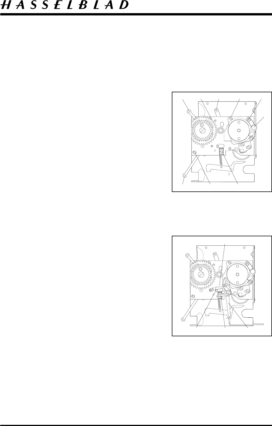
Fitting the mechanism plate to the right hand wall
On the mechanism plate fit the upper and lower
connecting rods to the pins on the gear wheels. (13100)
for the upper shutter and (13101) for the lower shutter.
Lubricate with grease. Position the auxiliary shutter stop
(22436) in place.
Place the mechanism plate in position on the right hand
wall. Attach the adjustable pawl assembly (13170) with
two screws (820022). Lubricate the pawl with a drop of
oil and ensure that it is free to operate. Attach the stop
angle (13432) with screw (821017).
Secure the mechanism plate with the remaining three
screws (823015), (820020) and (820015).
Note! The longer connecting rod (13101) which
operates the lower shutter is fitted below the lower-left
mounting post behind the signal arm.
Fig. 17.
Connect the push rod (22369) to the release arm
(13357). Place the arm on the pre-greased pin
(836514).
Fit the S-arm (21167), hub (840701), spring (816914)
and secure into position using screw (821032). Check
for ease of operation.
Connect the spring 816914 to the S-arm and position
the straight end to the pin on the shutter release
connecting rod reverse side. Connect spring (814826)
between the two pins. Check for ease of operation.
Fig. 18.
Fig. 17
Fig. 18
82301513100 820020 820022
13170
13101 820015 13432
13357
21167
816914
814826
22436
Camera body 503CW Reassembly
January 2001Revision 1
4:4
Fig. 19
Fig. 20
Fig. 21
Fig. 22
13355
13362
13280
13356-1
816720
30727
Cover 22813
814827
13108
821631
Fit the stop lever (13355) and spring (816752) to the
pre-greased hub. Secure with the clip (817119).
Lubricate the hub (13108) with grease and place a shim
onto it. This shim can be in several thicknesses for
adjustment as follows: 0.10; 0.20; 0.30 mm with
corresponding part numbers 810826, 810827, 810828.
Attach spring (814827) between the auxiliary shutter
stop (22436) and the right hand wall.
Fig. 19.
On the reverse side of the right hand wall fit the mirror
actuating lever (13362) and the lens lock (13280).
Lubricate with grease. The lens lock pin (13280) fits
into a pin on the mirror actuating lever.
Fig. 20.
Secure the mirror actuating lever (13362) temporarily
with screw (821631) from the other side according to
Fig. 19.
Fit the mirror catch 13356-1 onto the pin. Lubricate
with grease. Connect the spring (816720) with its long
shackle in the hole in the right hand wall and the short
one under the mirror catch.
Hold the blocking lever and spring and install the push
fit cover (30727). Check that the mirror catch moves
freely.
Fig. 21.
Connect the right and left hand walls to the bottom
plate (30686), secure with six screws (820014).
Apply safety lacquer to screw-threads.
Put back the foam plastic pad (22582).
Focusing screen frame (22812)
Put the focusing screen frame back and at the same time
secure the upper part of the inner side cover (22813).
Fit the spring (30755) and secure with screws (829425).
Fit four screws (820015), two through the right hand
wall and two (temporarily) through the left hand wall.
Fig. 22.
Camera body 503CW Reassembly
October 1996Revision 0
4:5
Rear plate (30300)
Fitting the rear plate
Fig. 23 and 24.
Lubricate the shutter driving arm’s shaft hub and the
mirror’s moving peg with grease. Connect the arm and
the connecting rods and fix the rear plate into the
chassis. Ensure that the mirror actuating lever grips the
pin on the mirror frame and that the mirror is
positioned correctly on the upper side of the mirror
support.
Connect the driving arm (22781) to the mirror frame
and secure with a clip (817115). Do not forget the
washer (810649) between the frame and the arm.
Check that the mirror and shutter driving arms move
freely.
Secure the rear plate to the camera using six screws
(820015) and two screws (821017).
Check that the mirror and the auxiliary shutters are
centred and move freely. Adjust if necessary the
brackets (Qty. 4) in the side hinges of the auxiliary
shutter and mirror frame.
If the magazine hook (22423) has been removed, put it
back with two screws (823640) and seal the screws with
loctite.
Seal between the rear plate and both side walls using
black silicone or similar. (Lower and upper end).
Fig. 23
Fig. 24
820015 820017
Camera body 503CW Reassembly
October 1996
Revision 0
4:6
Front plate (30777)
Fitting the front bayonet plate to the camera body
Tension the drive spring by turning the outer gear wheel
clockwise four turns. The front key will be positioned at
the red index dot.
A locking pin can be inserted through the inner cog
wheel and the bracket to prevent the spring from
unwinding.
Install the winding knob V-2206 and tension the gear
housing.
Note! Make sure the aux-shutter is closed at this time.
Fig.25.
Install the front bayonet plate. Ensure that the push rod
(22369) passes through the hole in the front plate and
that the lens lock pin (13280) passes through the
appropriate hole when the front plate is fitted and
secured.
Secure the two screws (823655) in the bottom plate
and seal with loctite. Secure the four screws (820015)
in the left and right hand walls, and the two screws
(821017) in the focusing screen frame.
Remove the temporary locking pin.
Fig. 26.
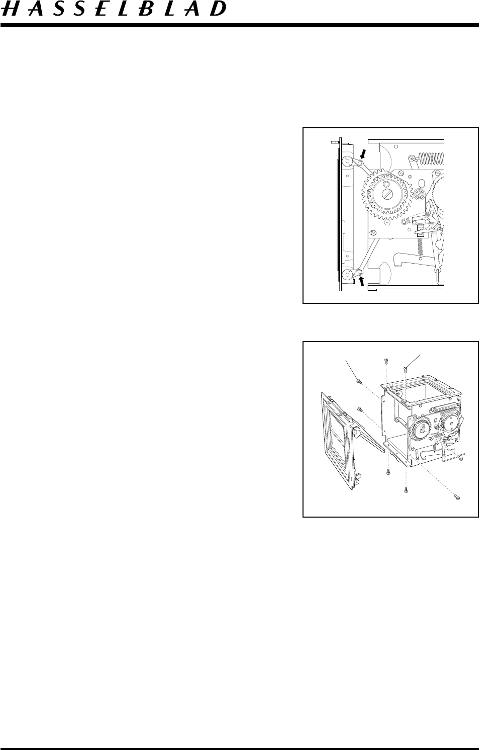
Intermediate gear (13112)
Remove the screw (821631) and fit gear wheel (13112).
Before meshing, align the gear (22699) with the rear
plate and ensure that the adjustable pawl (13170) is in
the middle cut out of ratchet wheel (20924).
Hold the mirror actuating lever from the inside and
secure the gear wheel (13112) with washer (810532)
and screw(821631).
Fig. 27.
Fit the release bar (30375) and the spring (814512).
Perform the necessary adjustment as described
in section 5.
Fig. 25
Fig. 26
Fig. 27
821631 13112 13170
20924
821017 820015
823655
Camera body 503CW Adjustment
October 1996
Revision 0
5:1
The lubricants mentioned in the text are:
Grease = Isoflex Topas L32
Oil = Isoflex PDP 48
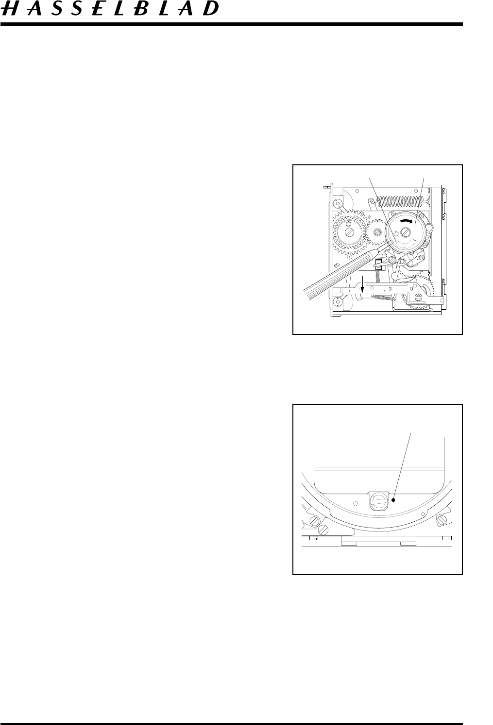
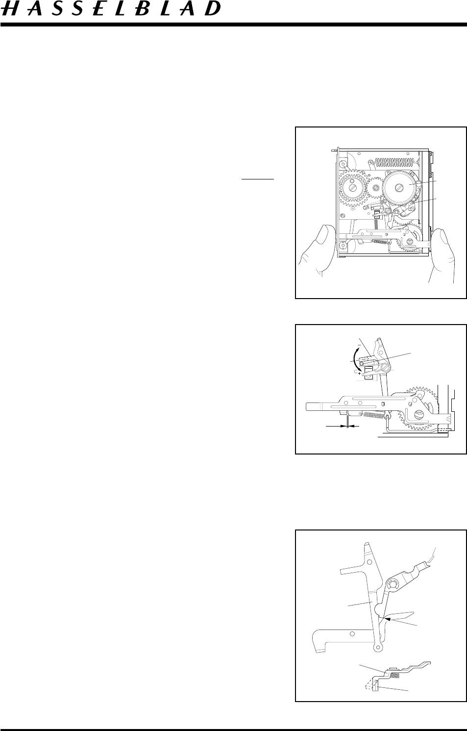
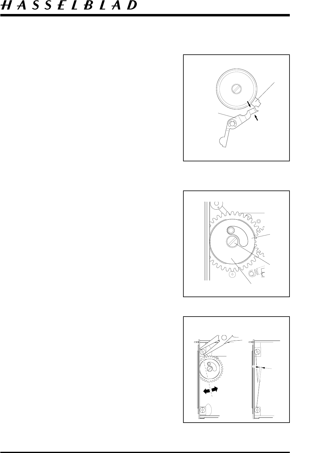
Install the winding knob V-2206 and tension the
auxiliary shutter spring (30384) by releasing the pawl
(20919). Turn the knob clockwise and tension the
spring two turns at this time. Test the camera’s
function.
If the spring is too tight the pressure can be reduced by
operation of the shutter mechanism and then pressing
the signal arm down.
Fig. 28.
Note! Always check that the auxiliary shutter is closed
before turning the winding knob, otherwise there is a
risk that the top flap of the shutter will be damaged
when the mirror moves downwards.
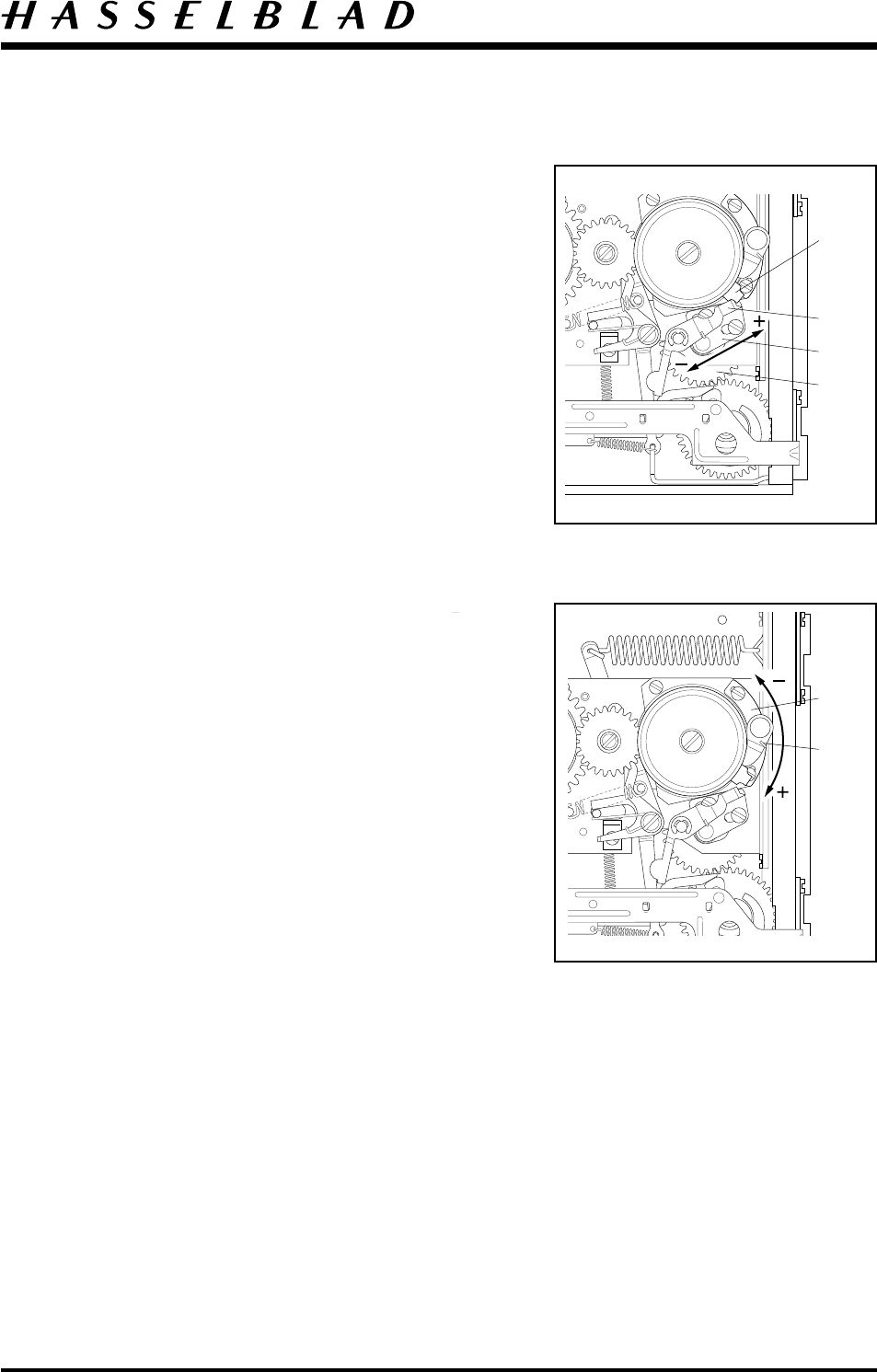
Temporarily adjust the key position by loosening the
screws and moving the bearing bracket (13171) forward
until the key position is aligned to the red index dot on
the front plate. If the adjustment is insufficient
disengage the cogs between the front gear wheel and the
gear wheel (13167). Hold the gear by hand during this
operation so that the drive spring tension is not lost.
Fig. 29.
Loosen the front plate just sufficiently to ensure that the
mesh of the teeth is removed and turn the gear one
tooth at a time.
Retighten the screws.
The camera body should now function normally, i.e.
shutter release and winding on can be carried out in the
normal manner.
Fig. 28
Fig. 29
20919 V-2206
Red dot
Camera body 503CW Adjustment
October 1996
Revision 0
5:2
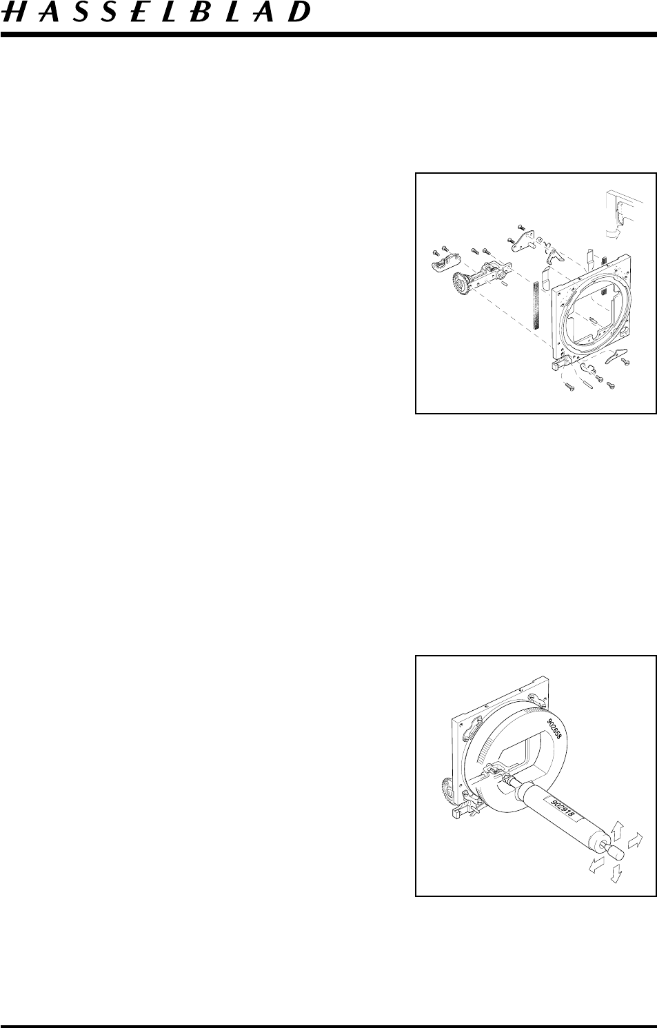
Focal length
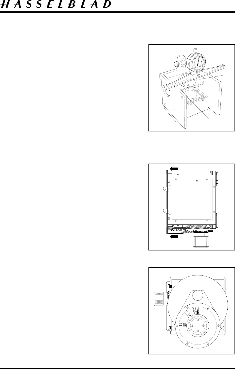
The camera body’s focal length is inspected and
adjusted by using tool V-2229. The focal length is
71.40 mm ± 0.03 mm.
Zero the dial indicator by placing it on surface ”A”.
Mount the front plate ”B” into the front bayonet of the
camera.
Connect the camera to the focal length gauge. Ensure
that the rear plate is flat. In the event of any unevenness
loosen the screws which hold the rear plate and push it
in the desired direction. Place the ruler with indicator
clock onto the gauge and move the indicator around the
periphery of the front plate and check that the length is
within the tolerance.
Fig. 30.
Adjustment is carried out by moving the camera rear
plate forward or backward.
Minor adjustments can be done by striking the front
plate tool with a plastic faced hammer.
Fig. 31.
Tighten up all screws.
Note! The focal length is checked once more when
the camera body is mounted in to the camera shell.
Adjustment of the front key’s angular position
Remove the knob V-2206 and insert the bayonet plate
tool 904644. Mount V-2206 again.
Mount the key inspection tool 902658 (V-2075) to the
camera’s front bayonet plate. Ensure the indicator is
pointing upwards when the camera is cocked.
Fig. 32.
Fig. 30
Fig. 32
"B"
Fig. 31
902658
"A"
Camera body 503CW Adjustment
October 1996
Revision 0
5:3
Adjustment No. 1 (Overtravel)
With the film winding mechanism tensioned, check the
angle 15-16o with the bayonet plate tool 904644 pushed
hard against the stop arm (13355). Measure the angle
with a spring tension of 300 gm/cm. Adjust by altering
the position of the bearing bracket (13171). When the
correct angle is achieved tighten the screws. Check that
meshing between intermediate gear (13167) and the
front drive gear is as close as possible without binding.
Fig. 33.
Adjustment No. 2 (Cocked position)
With the winding mechanism in the "free" position,
(no tension on the winding crank) adjust for an angle
of 8-9o by loosening the screws holding the adjustable
pawl (13170), and move it until the correct angle is
obtained. This measurement should also be carried out
at 300 gm/cm. When the adjustment is complete
tighten the screws.
Recheck adjustment No. 1 and secure the spring
(816507) with safety lacquer.
Fig. 34
Possible wear in the front gear (30383) can be checked
by increasing the spring pressure of the inspection tool
to 1400 gm/cm. The angle value should not fall below
3o. If it does the front gear (30383) should be replaced.
Inspection of the release sequence (angular value):
Free the mechanism by holding the release button
depressed (B-position). The indicator should read
between 268-273o at 300 gm/cm.
Let the mechanism turn to fully released position. The
angle should be 311o, tolerance: 306.5-321o.
Inspect the pre-released position, this should be 118o
with a tolerance 113-122o. If any of the measurements
are incorrect the possible cause will be in the bevel gear
or the stop gear (13509).
Remove tool 902658( V-2075).
Fig. 33
Fig. 34
904644
13167
13171
13355
816507
V-2206
V-2206
13170

Camera body 503CW Adjustment
October 1996
Revision 0
5:4
Adjustment of the release mechanism
Check that the release bar (30375) is free from the
signal arm pawl. Adjust by carefully bending the
forward part of the signal arm. Use tool V-2200.
Minimum free play: 0.2 mm.
With the camera fully cocked the release bar should
protrude a maximum of 0.9 mm through the rear plate.
Adjust this by bending the release arm (13357) using
tool V-2224.
Fig. 35.
The mirror function should be checked and possibly
adjusted before proceeding to adjust the release
mechanism.
The mirror should be locked by the mirror catch lever
(13356-1). Movement can be increased or reduced by
adjusting the mirror actuating lever (13362).
Adjustment is carried out by holding the arm fixed
using tool V-2205 and gently bend the forward part of
the arm using tool V-2201. Bend downwards for
increased mirror movement.
Note! The inner side cover (22813) must be removed
before an adjustment can be made.
The mirror’s overtravel should be min. 1 mm. Lubricate
the mirror cam (22355) with grease.
Fig. 36.
Fig. 36
min. 1 mm
1336222335
13357
max. 0.9mm Fig. 35
min. 0.2 mm 30375
13356-1
Camera body 503CW Adjustment
October 1996
Revision 0
5:5
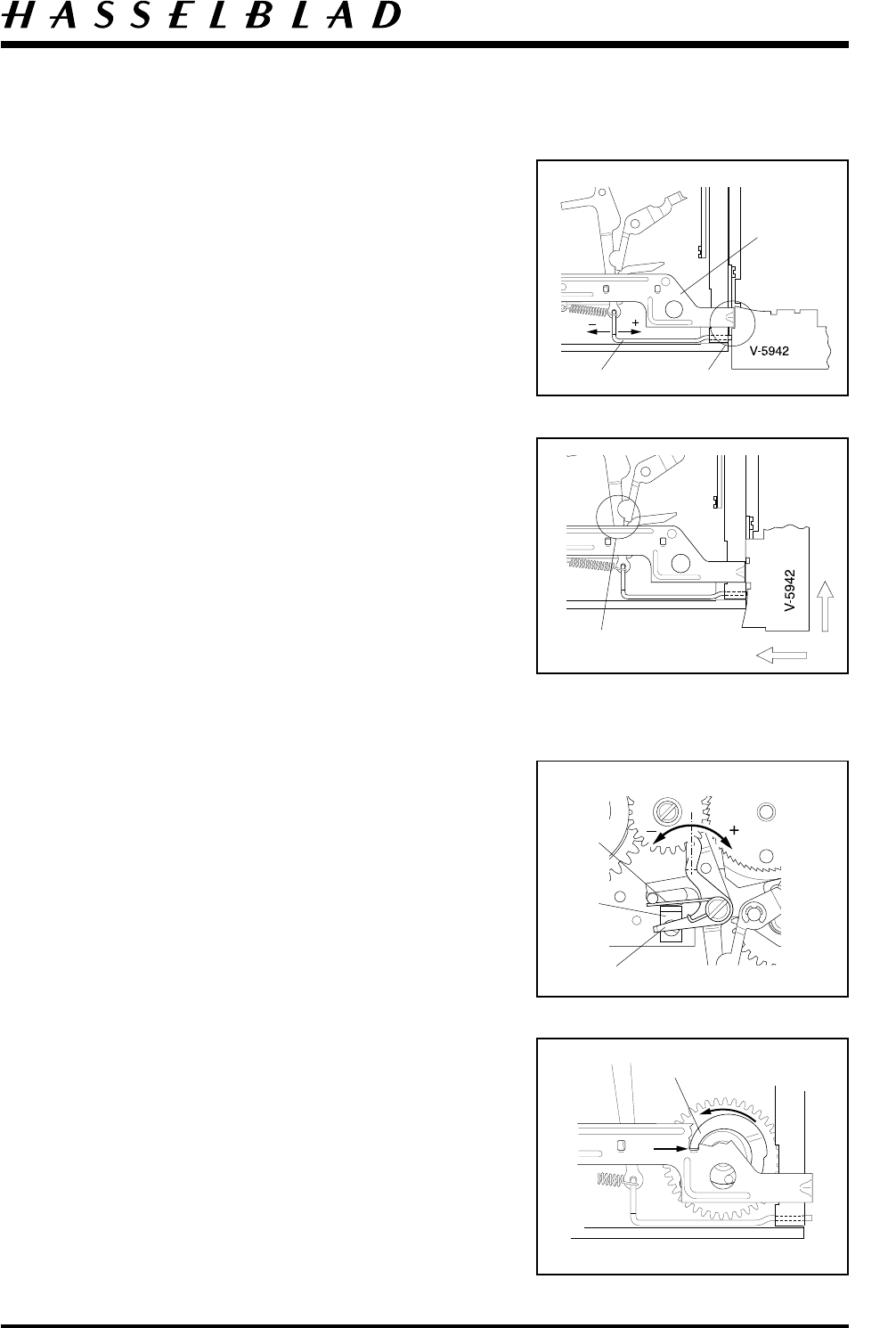
The push rod (22369) is adjusted so that it is set 0.15
mm below the release bar (30375) forward angle
setting. Check by using the tool V-5942.
Adjust by gently bending (22369).
Fig. 37.
Position tool V-5942 as shown and press against the
front plate. The mechanism should not release.
When the tool is moved upwards the mechanism should
release.
If a large adjustment is needed bend the release arm
(13357) using tool V-2224. Bend forward for an earlier
release and backwards for a delay in release. For a small
adjustment the push rod (22369) can be bent.
Fig. 38.
Fig. 39 and 40.
Pre-release the camera shutter by operating the S-arm
(21167) towards the angle stop (13432).
Shutter release should occur just as the S-arm strikes the
angled stop and at the same time cam ”A” should
be positioned on stop ”B”.
Adjust by bending the S-arm with tool V-2202.
Do not forget to re-adjust the angle stop (13432).
Minor adjustments can be carried out by just moving
or bending the angle stop (13432) without any
adjustments to the S-arm.
Note! That spring 816914 should not rest against the
angle stop when the camera is completely released.
Fig. 37
Fig. 38
Fig. 39
Fig. 40
22369 0.15 mm
30375
13357
Adjust here
with V-2224
13432
21167
816914
"B"
"A"
Camera body 503CW Adjustment
October 1996
Revision 0
5:6
Adjustment of the release sequence
Make sure the winding knob V-2206 and the bayonet
plate tool 904644 are installed.
Release the camera and keep it released by holding the
release bar and push rod back.
Move the release bar and push rod to the front slowly
and observe the closing sequence.
Fig. 41.
1. Key releases to fully released position.
2. Auxiliary shutter closes. Note that the winding knob
is blocked all the time until the auxiliary shutter
closes.
3. The stop lever disengage giving clearance for the
winding knob.
The auxiliary shutter closing position can be adjusted by
bending the rear of the release arm (13357) which bears
on pin ”A” as shown.
Use the tool V-2203.
Check for free play between the release bar and signal
arm when the camera is fully released.
Fig. 42.
Note! The final sequence check is done when the
chassis is mounted in to the shell by using the
exposure gauge V-2354. (See page 5:11).
Check that the auxiliary shutter does not close
spontaneously when the camera is pre-released. Carry
out a number of operations of the release arm (13357).
If the auxiliary shutters do close using this test, adjust
the tongue on lever (22769) which stops the release arm
against the signal arm.
Check the lever does not jam between the release arm
and the signal arm when the camera is released.
Test by operating the shutter and letting the release bar
return slowly. Check that the lever has a small amount
of play during this movement.
Fig. 43.
Fig. 41
Fig. 42
Fig. 43
904644
V-2206
"A"
13357
Free play
when fully released
Free play
Adjust here
22769
13357
Camera body 503CW Adjustment
October 1996Revision 0
5:7
Operate the winding knob V-2206 to cock the shutter.
Check that the bayonet plate tool 904644 is blocked by
the stop lever (22769) when the camera is completely
cocked.
Adjust by bending the front of the lever. The lever
engagement should be retained until the camera is fully
released.
Fig. 44.
Fitting the damping ring (22287)
Hold the lid (14280) in position and unscrew (822605).
Position the damping ring (22287). Lubricate carefully
with grease and insert washer (810836) with the
concave side facing up. Refit the screw and tighten.
Check for ease of movement. Operate the camera and
check that the auxiliary shutters close distinctively
without slamming.
Fig. 45.
Adjust the spring pressure if necessary. Test the
function by opening the shutter and letting it close
slowly. Both shutters should close steadily. Check that
the shutters are level to ensure a light seal around the
edge.
Operate the pre-release lever so that the camera
auxiliary shutters opens to the B-position.
Check that the auxiliary shutter blinds do not influence
on the light path. Alignment of the blinds can be
adjusted by holding the shaft using pliers and carefully
bending in the desired direction.
Check that the shutter pivot point is not loose on the
shaft. If this is the case a new shutter must be fitted.
Check that the top shutter is positioned 4-5 mm in
front of the lower shutter blind on closing.
Fig. 46.
Secure all screws with safety lacquer.
Fig. 44
Fig. 45
Fig. 46
904644
V-2206
22769
4 - 5 mm
14280
22287
822605
Camera body 503CW Adjustment
May 2000Revision 3
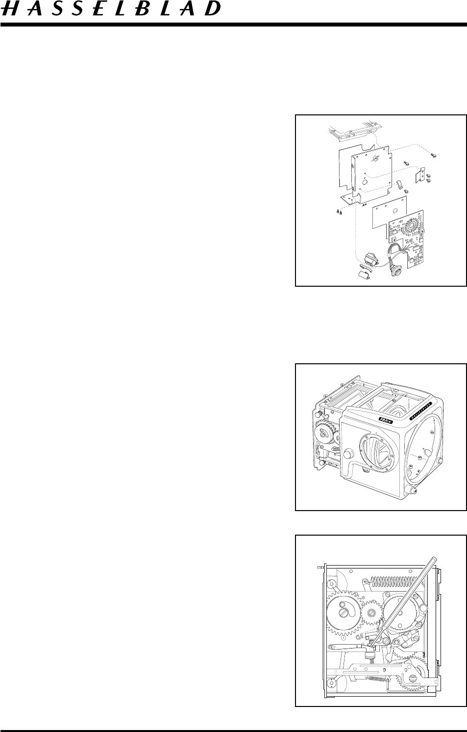
Fitting the Circuit board (22575) *22882
CAUTION! When handling the circuit board a
grounded bench mat and a wrist strap must be
used to prevent ESD damage.
Put the insulating plate (22746) in position and place
the circuit board on top of it. Secure the board by first
fitting the two screws (820015) followed by the
attachment (22453).
* Note! The circuit board (22882) is fixed to the wall
by an insulating double-sided tape, screws and
attachment.
Put the photo diode in position on the inside of the
bottom part of the left hand wall and secure from the
outside with two screws (820325).
Fit the cable holder (12453) and securing the cables
with screw (820011).
Fig. 47.
Fitting the camera body into the shell
Install the lens release button (13139), release button
(22759), buffer (22367), and the distance washers
(810620) into the shell.
Put the teflon cone (103373) in position on the camera
body.
The camera body can be fitted into the shell.
Fig. 48.
Note! That the S-arm (21167) has to be fitted using a
spring hook to ensure that the pre-lease button (22385)
is positioned beneath the S-lever.
Fig. 49.
* From camera serial No. 19ER18271
5:8
Fig. 48
Fig. 49
Fig. 47
Camera body 503CW Adjustment
January 2001
Revision 1
5:9
Adjust the lower rear plate/shell alignment and tighten
the two rear screws (829755)and seal with loctite.
Fit and tighten the two front screws (820781).
Check the upper edge alignment of rear plate and shell.
Adjust, if necessary, the two screws (825760) which are
accessible behind the leathers mounted on the shell.
Note! The rear edge of the shell must not protrude over
the rear plate at any point.
Fit the tripod foot (30763) with the remaining six
screws (829755). Screws sealed with loctite.
Fit the washer (22799) and coupling (22767). Secure
with screw (830060).
Fit the ISO selector knob and secure it with the screw
(822701). Fit the shim (22473) and leather (13374).
Do not damage the sliding contacts.
Fit the two screws (823335) behind the leather securing
the chassis connector.
Operate the pre-release on the camera body and fit the
front gear cover (22876) and a new side cover (22813),
if it has been removed.
The side cover is held in position by double sided tape
and the upper part of it held by the screen frame.
Mount the spring (30775) in the mirror box using the
small screwdriver (Tool No. 905020).
Mount the winding crank.
Operate the camera body and make sure it is working
properly.
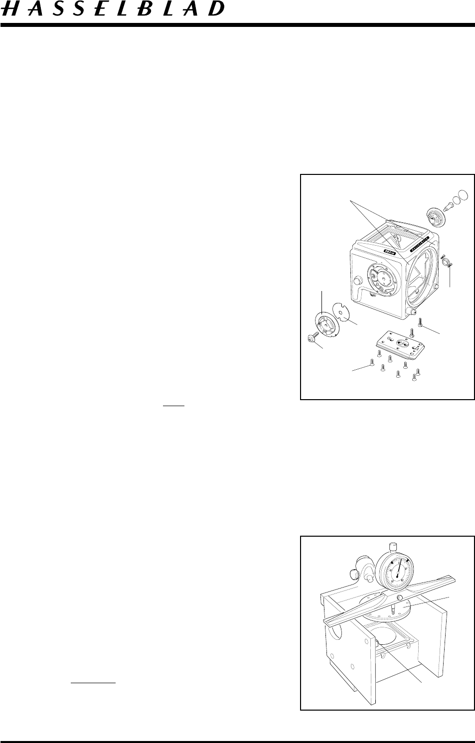
Final checks
Place the camera in the focusing gauge V-2229.
Zero the dial indicator by placing it on surface ”A”.
Mount the front plate ”B” into the front bayonet of the
camera. Place the ruler with indicator clock onto the
gauge and move the indicator around the periphery of
the front plate and check that the length is within the
tolerance ± 0.03 mm. If to long, the camera can be
shortened by carefully striking the plate with a plastic
hammer. (Focal length is 71.40 mm).
Note! If the camera is to short it must be taken out
from the shell again for an adjustment.
Fig. 50
Fig. 51
825760 are accessible
behind the leathers
829755
830060
22799
22767
ISO knob
820781
823335
"A"
"B"
Camera body 503CW Adjustment
January 2001
Revision 1
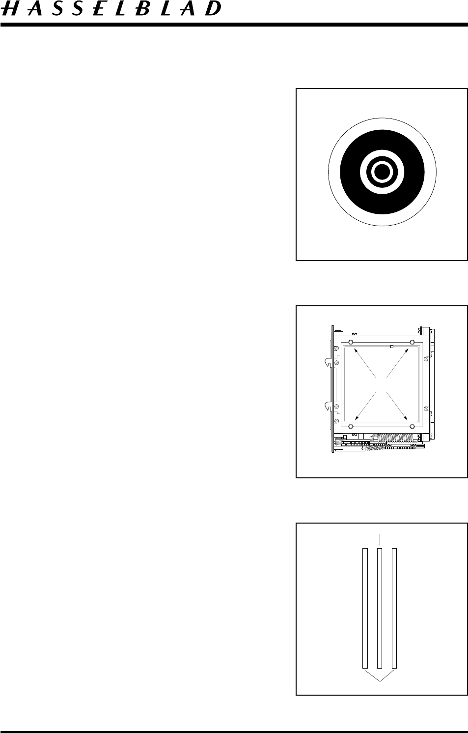
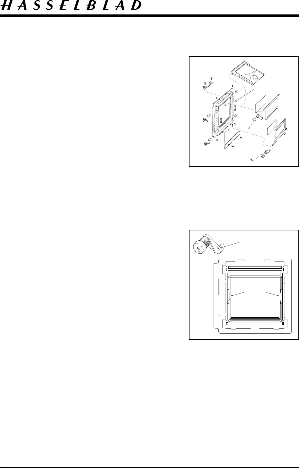
Check the mirror 45o angle using the sighting tube
which fits in the holder on the gauge. Tighten the
locking screw. Shine a light source towards the oval
cut-out in the upper part of the tube so that the white
ring of the ocular is illuminated.
When the mirror is at 45o the pattern in the sighting
tube will appear as shown.
Check that the inner white circle is symmetrical and
does not lie outside the inner black field.
The mirror level is adjusted by bending the mirror
support (13121) on the left hand wall and/or the mirror
catch lever (13356-1).
Fig. 52.
After adjustment is completed remove the sighting
tube.
To adjust the screen position there are four special
screws (21606) in the screen frame. Use key V-4704
for the adjustment. Each rotation of the screw alters the
height by 0.35 mm. A cross is engraved on the tool’s
upper surface to help determine the amount of
adjustment that has been carried out.
First check the flatness of the screen. Use the screen
adapter V-4705 and the ruler with the indicator clock.
The same measurement should be obtained at all four
corners.
Fig. 53.
Then fit tool V-4151 into the camera’s front bayonet
plate. The tool should be powered by 6 volt DC.
Position the microscope V-2236 on the screen adapter
V-4705. Adjust (all four screws) the screen height with
V-4704 until the green line is central between the two
red lines.
Use the engraved cross on tool as reference.
Fig. 54.
Remove the camera body from V-2229 and secure the
screws (21606) with safety lacquer.
5:10
Fig. 52
Fig. 53
Fig. 54
21606
Green line
Red lines

Camera body 503CW Adjustment
October 1996
Revision 0
5:11
Check the camera functions. Check that the auxiliary
shutter is clear of the internal covers.
Check the release sequence using a micrometer V-2354.
Mount the micrometer in the exposure button’s cable
release socket. Carefully screw in the micrometer’s
screw until the camera releases. After releasing it should
be possible to turn the micrometer a further 3 to 5
notches before it bottoms. Screw out the micrometer
slowly and observe the closing sequence.
1. Key releases to fully released position.
2. Auxiliary shutter closes. Note that the winding knob
is blocked all the time until the auxiliary shutter
closes.
3. The stop lever disengage giving clearance for the
winding knob.
Note! If the release sequence is incorrect the camera
should be dismantled from the camera shell and
adjusted as previously described in section "adjustment
of the release mechanism", page 5:6.
Check that a magazine can be fitted on the camera and
that the locking functions work properly.
If the lock does not function the magazine hook can be
adjusted by filing.
Ensure when filing that tests are made often and finally
that the magazine fits snugly otherwise it will result in
play between the camera body and the magazine.
Mount the screen and the focusing hood.
Test run the camera with loaded magazine and a lens
fitted.
Check the flash metering system.

Camera body 503CW Adjustment
June 1998Revision 1
5:12
Calibration and control of the flash metering system TTL
Control/calibration should be carried out each time the camera has been in for repair.
The tolerance for the flash meter is ±0.3 EV at all settings.
If the Hasselblad Service System 970600 is used, follow the step by step instruction in the
STS user manual.
Note! For calibration work use ISO 100 and LV15. * (ISO 400/LV12).
If the Test box 902474 is used follow the instruction below.
Calibration requires the following test equipment:
- Planar CF80 mm lens with controlled diaphragm values.
Deviation max. ±10%.
- Magazine fitted with Kodak´s grey card.
- Stabilized DC power supply adjustable to 7.5 volt ± 0.1 volt.
- Calibrated light box with LV12 and 15.
- Test box 902474.
- Non-conductive trimmer, 2 - 2,5mm.
Set-up for calibration:
Lens Shutter B or F
Aperture f 5.6
Camera body ISO 100 * (400)
Magazine Fitted with
grey card
Test box 902474 Exposure knob 0 * (+1)
Tolerance knob Trim
Power supply Voltage 7.5 ± 0.1v
Light box LV 15 * (12)
K-factor 1.3
* From camera serial No. from 19ER18271 - See Service info No. 12/98
Link to: VHABSTS
Camera body 503CW Adjustment
June 1998
Revision 1
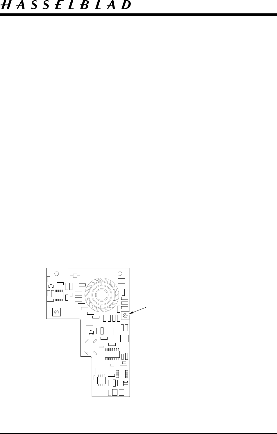
Calibration
On pressing the MEASURE button one of the three LED´s will light. The variable resistor
in the camera (access behind the leather beside the ISO dial) should be turned so that the
green LED lights when the MEASURE button is pressed again.
If the red LED lights, the resistor is turned anticlockwise and if the yellow LED lights, it is
turned clockwise. At least two seconds must be allowed between measurements.
Control
To ensure the ISO dial functions, the measurement should also be made for two other
ISO settings (50 and 800). * (100 and 1600).
In each case the green LED should light when the MEASURE button is pressed.
ISO Exposure knob Tolerance knob LV
50 + 1 1/2 15
800 0 1/2 12
100 0 1/2 15
1600 - 1 1/2 12
5:13
Variable resistor
* From camera serial No. from 19ER18271 - See Service info No. 12/98
Camera body 503CW
October 1996Revision 0
6:1
Front bayonet plate
Front plate reassembly
Fit the four bayonet tongues (103439) and secure with
eight screws (820425).
Fit the release button return spring (21096) with one
screw (820015).
Behind the front plate glue the two sponge seals
(13212) and (13213) as well as the foils (22829) and
(22832) into place.
Place the lens catch lever (103440) in position and fit
the cover plate (105107). Secure with screw (823440).
Install the spacer (810409) and the spring (816858).
Secure the second screw (823440). Check the lens catch
lever for ease of operation.
Front gear (30383)
Check the front gear ease of operation. The long shaft
from the drive gear wheel to the bevel gear wheel
sometimes has too little play which can give rise to
tightness. A light blow with a plastic faced hammer on
the cog wheel end of the shaft will generally overcome
the problem.
Fit the front gear on the front bayonet plate using one
screw (823019) in the front and one (820018) from the
rear. Check the freedom of operation. Do not tighten
the screws to much.
Centring the front gear key.
Mount the tool 902658 (V-2075) into the lens bayonet
plate and connect tool 902918 (V-2219). Turn the key
using 902918 to a vertical position. Check that the free
play is even in both directions. If there is more
resistance at one direction than the other move the front
gear to obtain a balance. Carry out the same procedure
with the key in a horizontal position. Also check at the
180o points in both vertical and horizontal position.
When the key is centralised tighten both screws in the
front gear and secure with safety lacquer.
Fig. 55
Fig. 56

Camera body 503CW
October 1996
Revision 0
6:2
The hole for the locating pin (812202) is bored with
1.15 mm drill. Use tool V-2211 for driving in the pin.
Drive the pin in until the face of the tool touches the
front bayonet plate. When a new front plate is installed
the hole must be drilled using tool 902658 (V-2075),
which is equipped with two drill bushes.
Fit the governor (30386) using two screws (820014),
ensure the gears mesh and then secure the screws.
Remove the swarf and lubricate the bevel gears with
grease. Force grease using a syringe into the three small
holes and lubricate the weight of the centrifugal brake.
Note! Do not over lubricate.
Front bayonet plate
Fig. 57
V-2211
1.40 mm
Camera body 503CW
October 1996Revision 0
6:3
Auxillary shutter & Mirror
Exchanging the mirror (22775)
Release the camera.
Inside the mirror box, remove the clip "A" and
disengage the arm (22781) from the mirror frame.
Remove the washer (810649) located behind the arm
and the frame.
Remove the sleeve (22800).
Fig. 58.
Carefully wind on until the mirror is visible in the front
plate cut-away.
Remove the mirror (22775) and the light trap (22776)
which is placed underneath the mirror.
Fig. 59.
After a new mirror has been mounted in to the frame
check for ease of operation.
Mount a new sleeve (22800) with the counter sunk side
facing out.
Note! If the spring (22804) has to be replaced, the new
one should be glued in the mirror frame with
Loctite 480.
Exchanging the auxiliary shutter
Note! For convenience use the aux. shutter jig V-5423
when removing/mounting the pins (811108).
Remove the two pins (811108), spring retainer, spring
(816805) and lever 13185.
Remove the safety lacquer and loosen the locking screws
(825661). Remove the hubs (840514).
The upper shutter flap and mirror frame can now be
removed. Ensure that all adjustment washers on the
shaft are retained. The lower shutter flap is dismantled
in a similar manner. The light trap 13125 is held in
place by two screws (821203).
Fig. 60.
Fig. 58
Fig. 59
Fig. 60
816805
811108
13125
13185
840514
825661
"A"
22800
22781
810649
Camera body 503CW
October 1996Revision 0
6:4
Remount the mirror frame and the upper shutter flap
by holding the frame in position and aligning the upper
shutter flap to the bearing holes.
Push in both bearing hubs and centralise the mirror and
shutter flap side movement by using shim washers.
These come in two thicknesses 0.10 and 0.20 mm
(810503) and (810505) respectively.
Tighten up both screws (825661) and secure with safety
lacquer.
Fit a washer (810503) on each side of the lower shutter
flap shaft and mount in the same way as the upper one.
Check that the shutter flaps and the mirror frame move
freely and that the flaps are central to the rear plate
inner frame.
Fig. 61.
Check that the foam plastic dampers (13397) are in
place and glued to the rear plate where the flaps meet.
Assemble the lever, spring and spring retainer. Locate
the spring so the three items are together.
Connect the three items to the shutter shaft and secure
it with pin (811108).
Fig. 62.
The lower shutter is completed in the same manner but
note that a weaker spring is used, (816804).
Check that the upper shutter spring pressure is
approximately twice as strong as the lower shutter.
Auxillary shutter & Mirror
Fig. 61
Shim washers
Fig. 62
13397
Spring retainer
assembly
BOD50301.EPS
970512
COPYRIGHT © 1997 ANDERS ENGSTRÖM
ANDERS ENGSTRÖM, ILLUSTRATÖR
Östra vägen 46
430 91 HÖNÖ
tel/fax 031- 96 84 64
anders@aeillustr.se
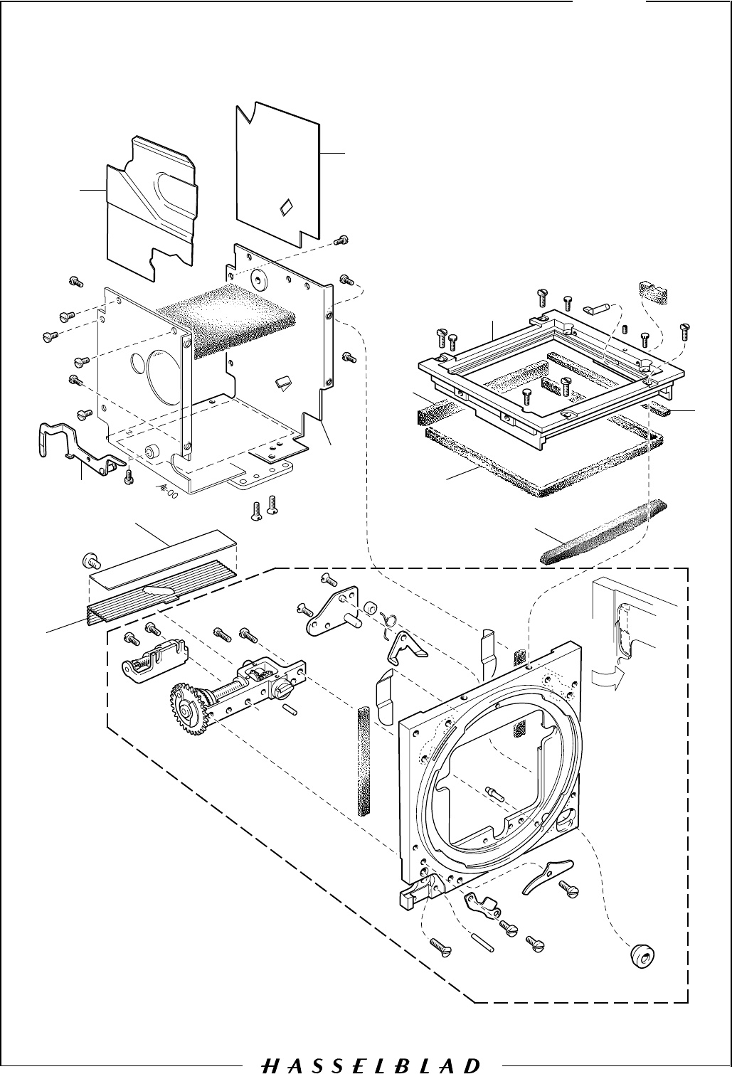
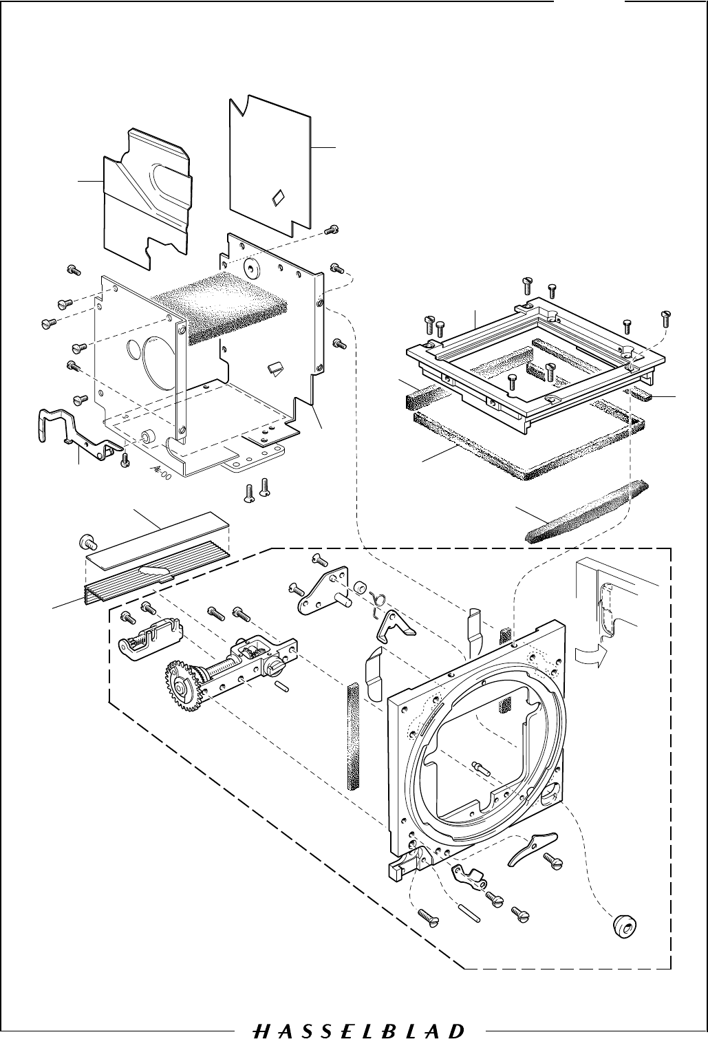
7
Camera body 503CW
May 1997
Revision 1
14
234
5
6
7
8
9
10
12
13
15
16
17
18
19
15
20
21
23
22
24 25 26 27 28
29
30
31
32
35 36
37
38
40 41 4243
44
45
47
48
49
50
51
52
53
54
55
11
14
39
46
33
34
1
56

Description
Pos
No. Pcs Spare
Part No. Remark
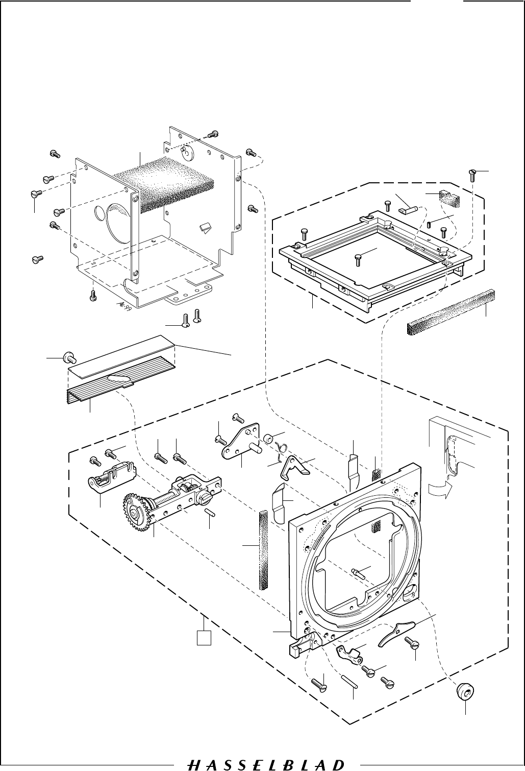
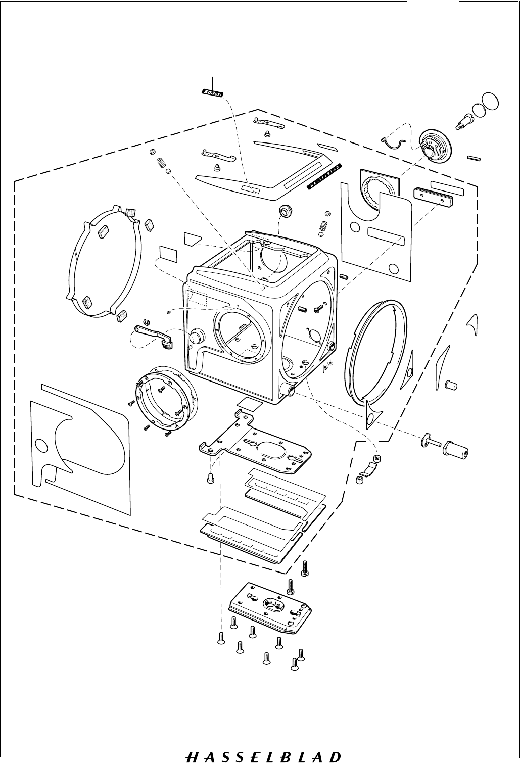
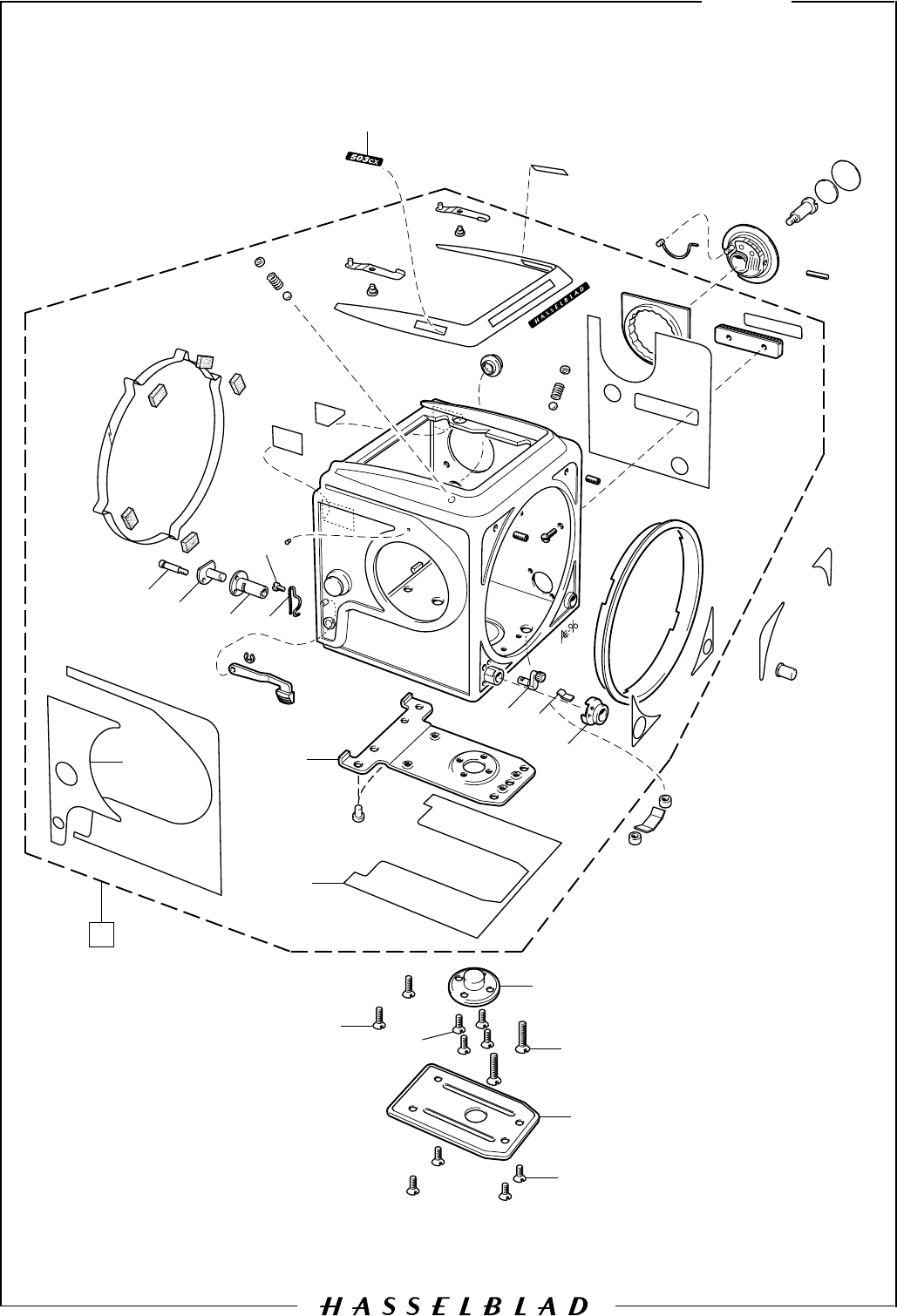
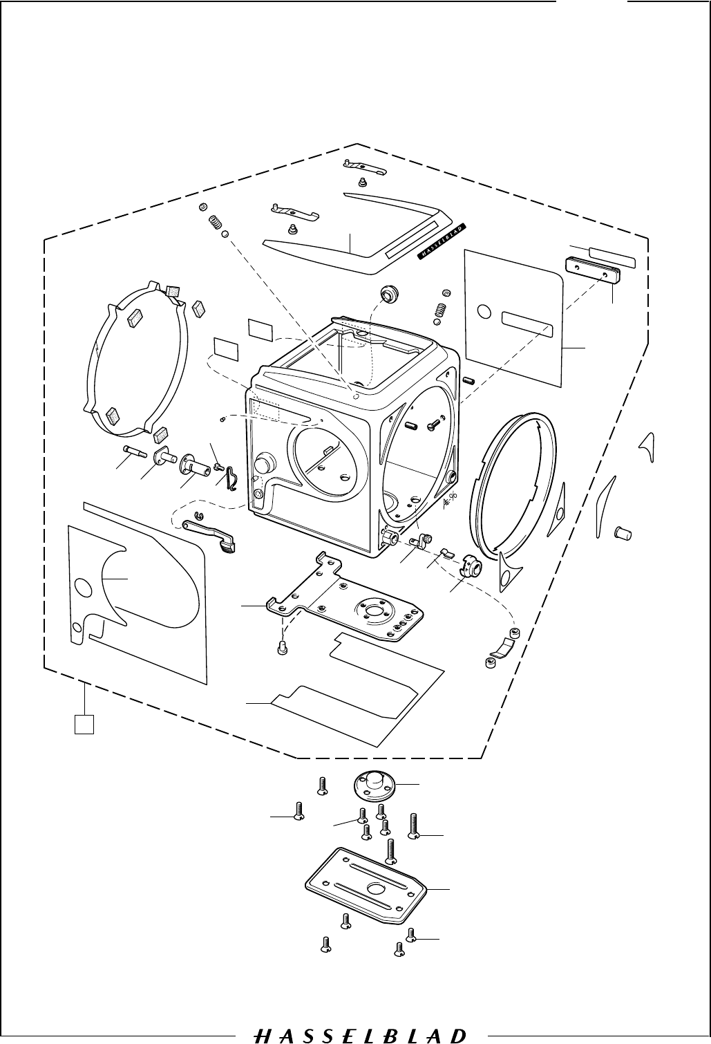
Camera body 503CW 7
June 1998
Revision 2
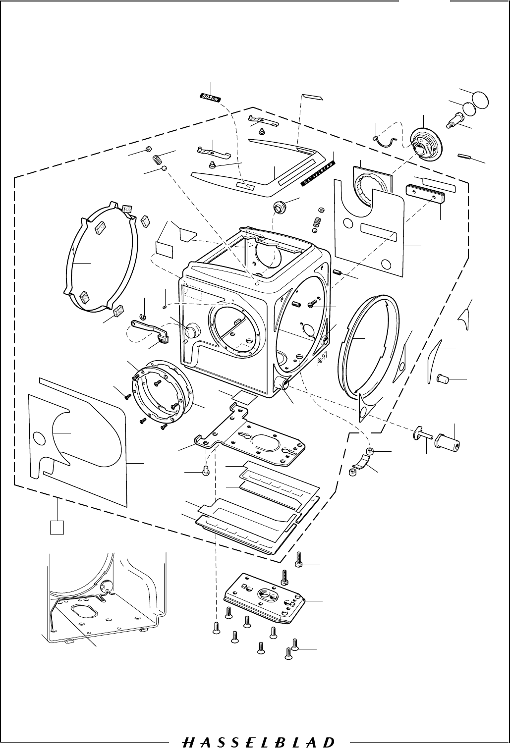
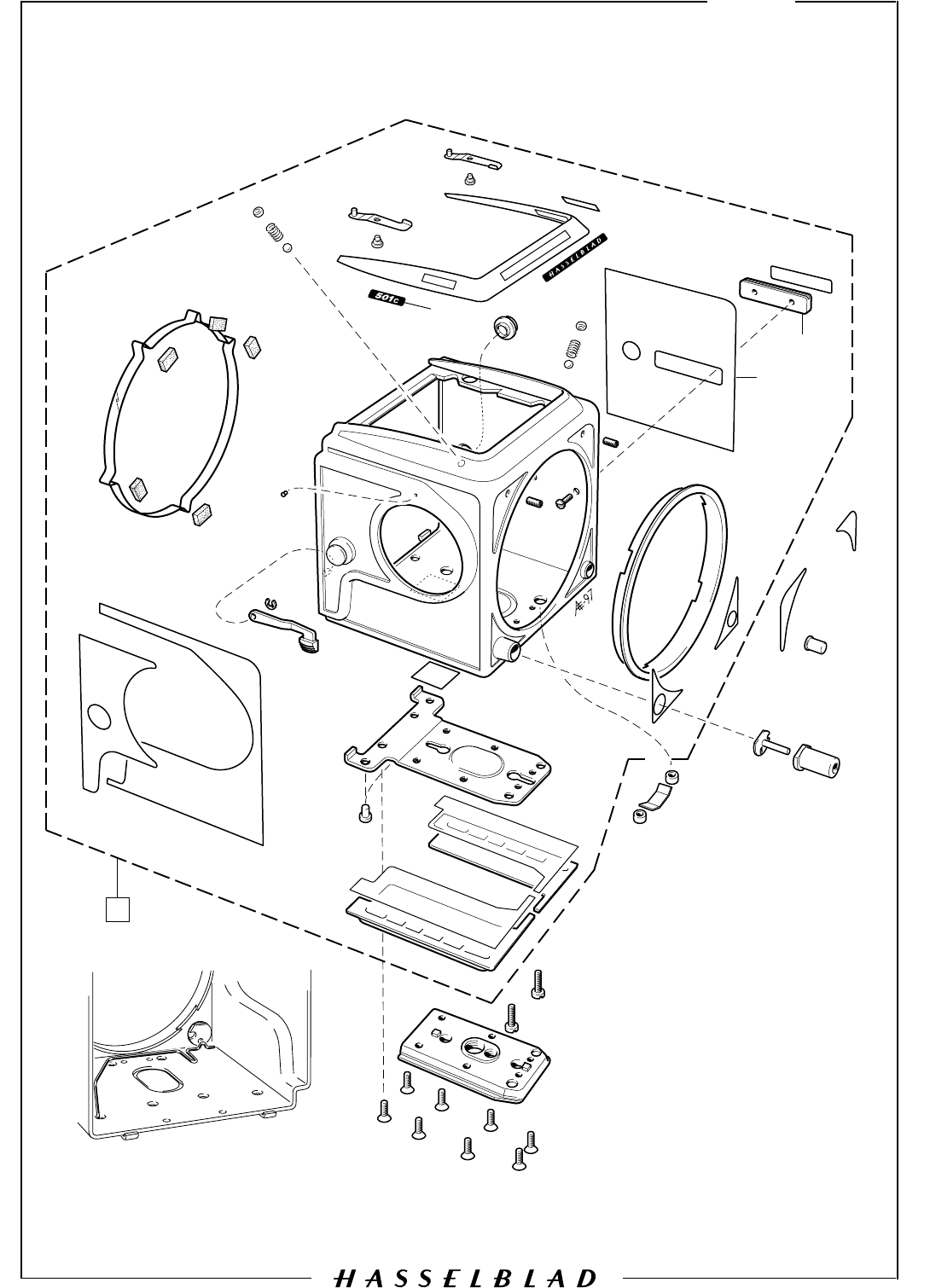
1 1 40 393 Shell, complete (chrome) Part No. 40394 (black)
2 1 30 762 Support, right
3 1 105 872 Tape
4 1 30 760 Support, left
5 1 105 870 Tape
6 2 831 502 Rivet
7 1 40 387 Support
8 1 103 504 Leather
9 1 105 509 Leather
10 6 829 304 Screw
11 1 103 387 Bayonet
12 1 22 385 Quick release arm
13 1 103 388 Bayonet spring
14 3 22 514 Reflection protector
15 2 13 466 Strap button
16 1 103 536 Index
17 1 817 112 Clip
18 5 13 315 Foam plastic pad
19 1 22 515 Locking ring
20 1 105 926 Leather
21 2 835 001 Rivet
22 2 809 120 Steel ball
23 2 12 978 Plate
24 2 815 604 Spring
25 1 13 906 Holder, right
26 1 13 907 Holder, left
27 1 13 190 Name plate
28 1 40 331 ISO plate
1 40 417 ISO plate From camera serial No. 19ER18271
29 1 22 607 Leather
30 1 22 472 Accessory rail
31 1 22 455 Leather
32 2 825 760 Screw
33 2 821 661 Screw
34 1 105 498 Bushing
35 1 22 516 Front ring
36 1 103 510 Leather
37 1 103 509 Leather
38 1 105 357 Bushing
39 2 22 502 Name plate
40 1 22 587 Spring
41 1 22 495 ISO Selector
42 1 22 473 Shim
43 1 13 374 Leather
44 1 822 701 Screw
45 1 22 533 Dog
46 1 103 508 Leather
47 1 103 507 Leather
48 1 13 139 Lens release button
49 1 22 759 Release button
50 1 22 367 Buffer
51 2 810 620 Spacer
52 1 103 424 Spring
53 2 820 781 Screw
54 1 30763 Tripod foot
55 8 829 755 Screw
56 1 22 850 Spring From serial No. 19EU11261
(Replaces p/n 21096, page 11)
-1
BOD50302.E
P
00050
COPYRIGHT
ANDERS ENGSTR
430 91 H
tel/fax 031-
anders@aeillustr.se
Camera body 503CW 8
May 2000
Revision 2
2
4
3
5
6
7
8
9
12
16
17
18
19
20
21
22
1
10
11
13
15
23
24 25
26
27
28
29
30
31
32
14

Description
Pos
No. Pcs Spare
Part No. Remark
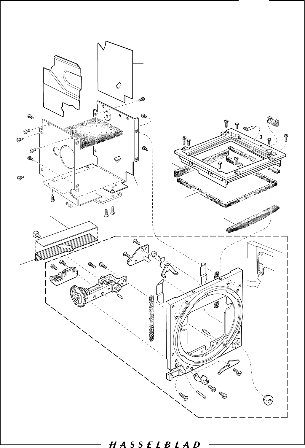
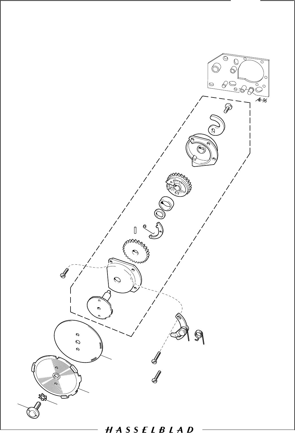
Camera body 503CW 8
May 2000
Revision 2
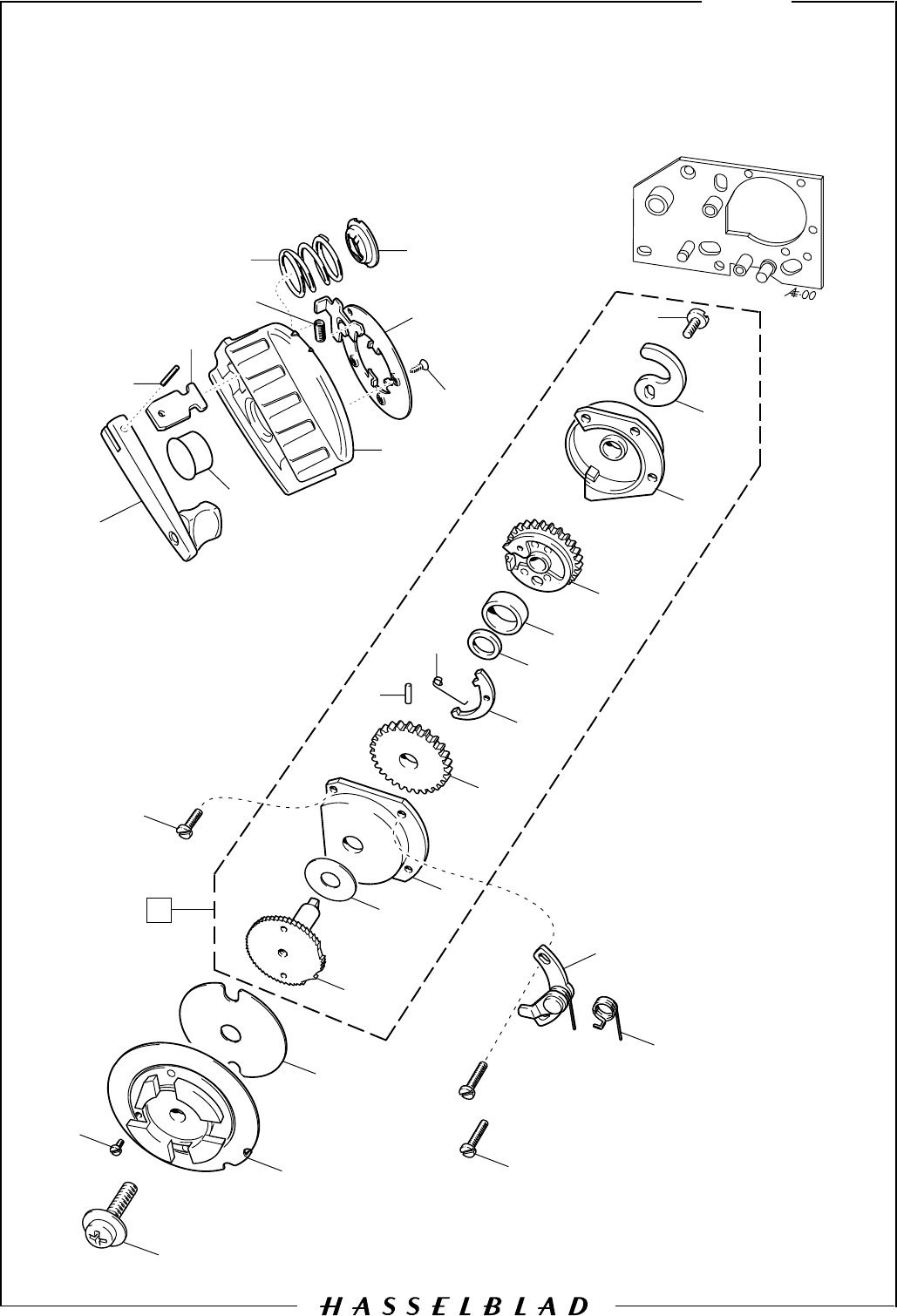
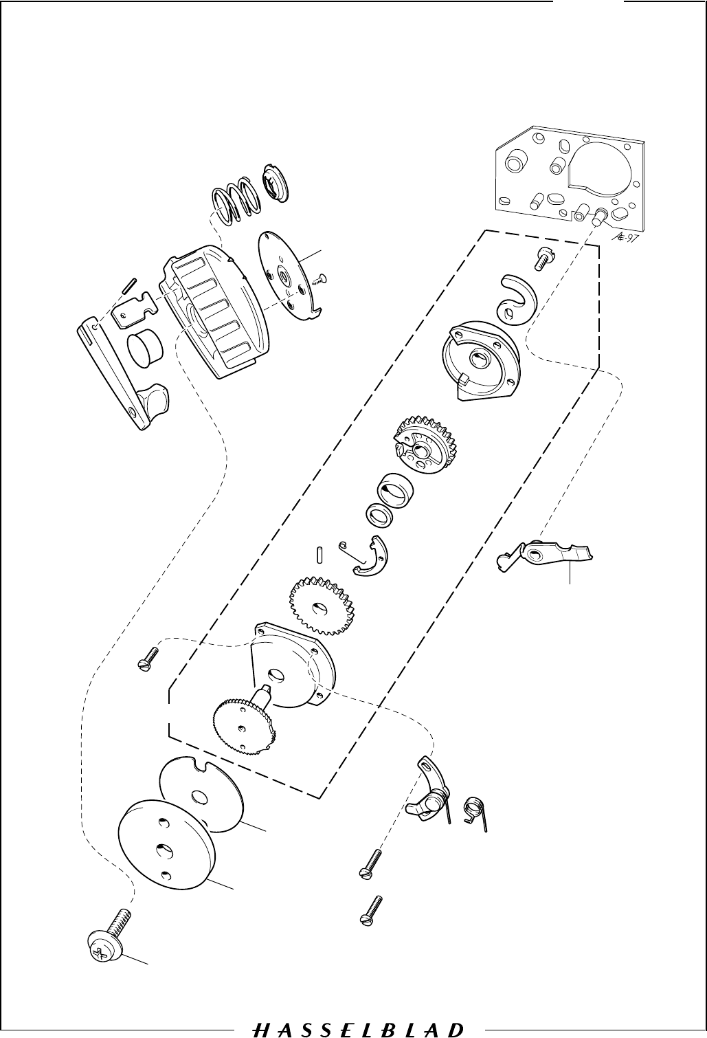
1 1 30 324 Gear housing Complete
2 1 830 060 Screw
3 1 820 415 Screw
4 1 22 767 Coupling
5 1 22 799 Washer Alternatively 2 pcs
6 2 820 020 Screw
7 1 816 507 Spring
8 1 13 170 Adjustable pawl
9 1 820 019 Screw
10 1 20 924 Ratchet wheel
11 1 810 840 Washer
12 1 30 304 Gear housing, front
13 1 13 169 Gear
14 1 812 106 Pin
15 1 816 504 Spring
16 1 20 919 Hook
17 1 810 826 Washer
18 1 810 938 Locking ring
19 1 13 509 Stop gear
20 1 13 157 Gear housing, rear
21 1 22 355 Mirror cam
22 1 821 033 Screw
23 1 815 707 Spring New type of winding crank from
24 1 815 904 Spring camera serial No. 19EU11514
25 1 103 516 Washer
26 1 412 105 Crank bayonet
27 3 826 401 Screw
28 1 412 323 Crank support
29 1 412 104 Crank arm
30 1 103 514 Slide
31 1 812 301 Pin
32 1 22 683 Rubber plug
BOD50303.EPS
970515
COPYRIGHT © 1997 ANDERS ENGSTRÖM
ANDERS ENGSTRÖM, ILLUSTRATÖR
Östra vägen 46
430 91 HÖNÖ
tel/fax 031- 96 84 64
anders@aeillustr.se
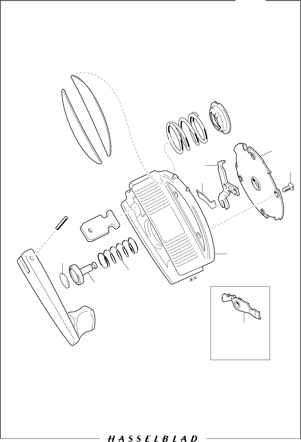
9
May 1997
Revision 1
Camera body 503CW
1
2
3
4
5
6
7
8
10
12
14
16
17
18
19
15
23
22
24
26
25
27
28
29
30
31
32
33
34
35
36
37
9
11
20
21
39
40
41
38 13

Description
Pos
No. Pcs Spare
Part No. Remark
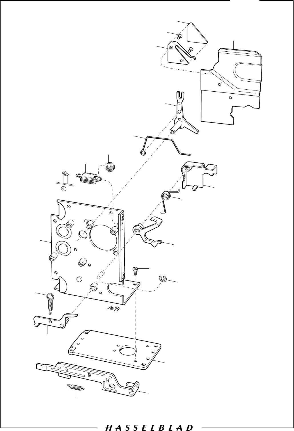
Camera body 503CW 9
May 1997Revision 1
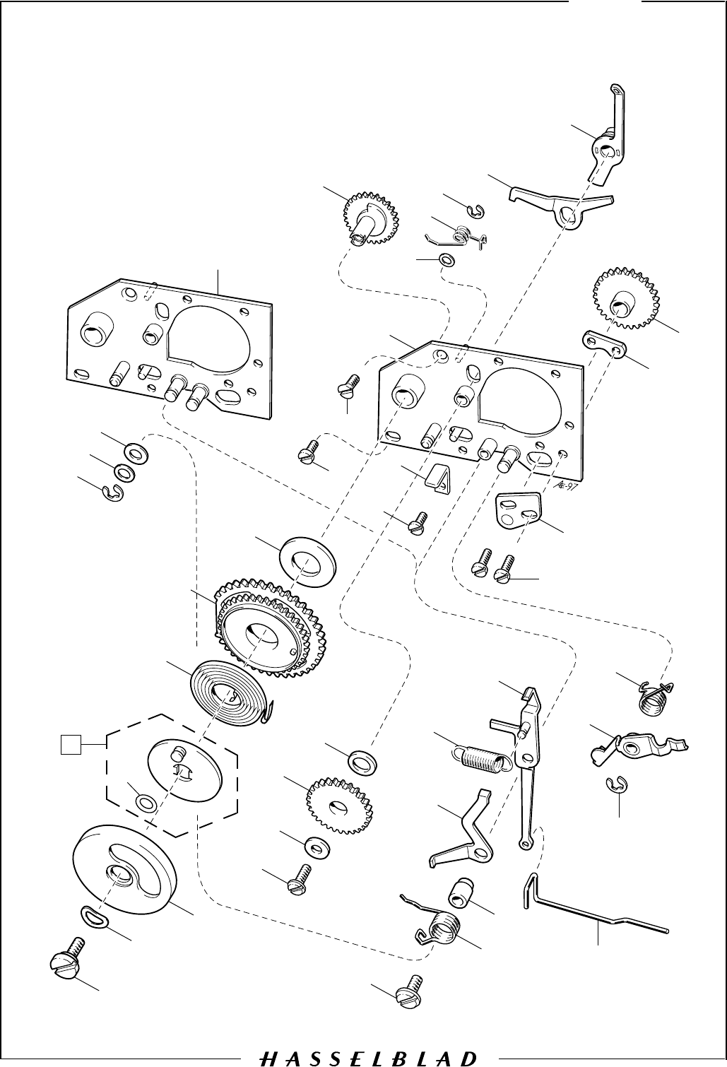
1 1 822 605 Screw
2 1 810 836 Washer
3 1 22 287 Damping ring
4 1 14 280 Lid
5 1 14 278 O-ring
6 1 30 384 Spring
7 1 22 699 Gear
8 1 810 953 Washer (0.3 mm)
9 1 820 015 Screw
10 1 823 015 Screw
11 1 21 125 Mechanism plate
12 1 13 182 Gear
13 1 810 404 Washer (0.3 mm)
14 1 816 802 Spring
15 1 817 112 Clip
16 1 821 631 Screw
17 1 810 532 Washer
18 1 13 112 Gear
19 1 810 826 Washer (0.10 mm) For adjustment 810 827 (0.20 mm)
20 1 20 912 Stop bar
21 1 22 436 Aux. shutter stop
22 1 821 017 Screw
23 1 13 432 Stop angle
24 1 821 032 Screw
25 1 816 914 Spring
26 1 840 701 Hub
27 1 21 167 S-arm
28 1 814 826 Spring
29 1 13 357 Release arm
30 1 22 369 Push rod
31 1 817 119 Clip
32 1 22 769 Stop lever
33 1 816 752 Spring
34 2 820 016 Screw
35 1 13 171 Bearing bracket
36 1 13 116 Fixing plate
37 1 13 167 Gear
38 1 21 125 Mechanism plate From serial No. 19ET10850
39 1 810 729 Washer (0.5 mm) "
40 1 810 705 Washer (0.2 mm) "
41 1 817 119 Clip "
-1
-1
BOD50304.EPS
990906
COPYRIGHT © 1999 ANDERS ENGSTRÖM
ANDERS ENGSTRÖM, ILLUSTRATÖR
Östra vägen 46
430 91 HÖNÖ
tel/fax 031- 96 84 64
anders@aeillustr.se
Camera body 503CW 10
September 1999
Revision 1
1
2
3
4
56
7
8
9
10
11
12 13
14
15
16
17
18
19
20
21
22
23
24
25
26
27
28
29 30
10
31
32

Description
Pos
No. Pcs Spare
Part No. Remark
Camera body 503CW 10
September 1999
Revision 1
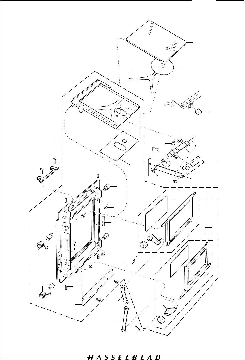
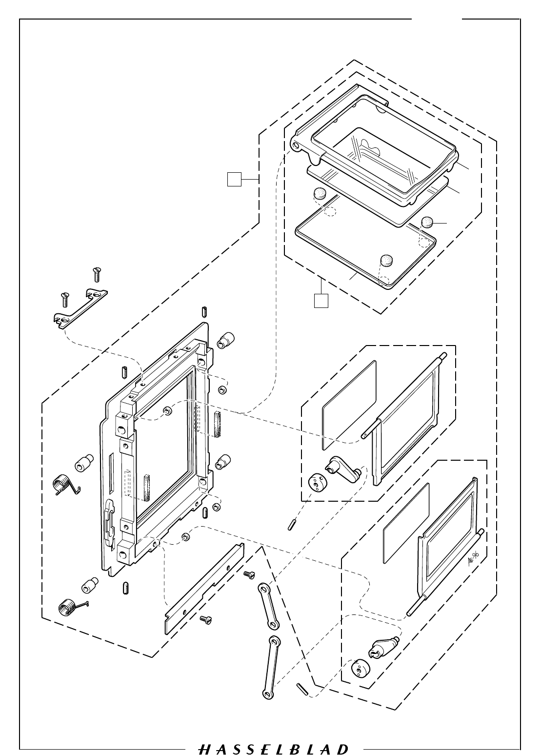
1 1 30 300 Rear plate, complete State serial No.
2 1 40 237 Rear plate State serial No.
3 1 816 805 Spring
4 1 816 804 Spring
5 1 13 125 Light trap
6 2 821 203 Screw
7 2 13 397 Foam plastic strip
8 4 810503 Washer (0.10 mm) For adjustment 810 505 (0.20 mm)
9 4 840 514 Hub
10 4 825 661 Screw
11 1 30 770 Mirror frame Incl. reflection protector 22 874
12 1 22 419 Reflection protector
13 1 90 711 Top flap
14 1 90 712 Bottom flap
15 1 22 420 Reflection protector
16 2 13 185 Lever
17 2 811 108 Pin
18 1 13 100 Connecting rod
19 1 13 101 Connecting rod
20 1 22 423 Magazine hook
21 2 823 640 Screw
22 1 22 775 Mirror
23 1 22 776 Light trap
24 1 22 804 Spring
25 1 22 819 Magnet
26 1 22 878 Arm Incl. reflection protector 22 875
27 1 810 649 Washer
28 1 22 800 Sleeve
29 3 817 115 Clip
30 1 22 779 Driving arm
31 1 22 875 Reflection protector
32 1 22 874 Reflection protector
BOD50305.EPS
990906
COPYRIGHT © 1999 ANDERS ENGSTRÖM
ANDERS ENGSTRÖM, ILLUSTRATÖR
Östra vägen 46
430 91 HÖNÖ
tel/fax 031- 96 84 64
anders@aeillustr.se
September 1999Revision 2
11
Camera body 503CW
12
3
4
567
8
9
10
11
12 13
15
14 17
16
18
19
20
21
22
23
24
25
26
27
28
29
30
32
33 34
36
31 37
35
38

Description
Pos
No. Pcs Spare
Part No. Remark
Camera body 503CW 11
September 1999Revision 2
1 1 30 777 Front bayonet plate Complete
2 1 40 403 Front bayonet plate
3 1 30 383 Front gear
4 1 30 386 Governor
5 2 820 014 Screw
6 1 821 009 Screw
7 1 820 018 Screw
8 1 812 202 Pin
9 2 823 440 Screw
10 1 105 107 Cover plate
11 1 810 409 Spacer
12 1 816 858 Spring
13 1 103 440 Lens catch
14 1 22 832 Foil, left
15 1 22 829 Foil, right
16 1 13 213 Foam plastic strip
17 1 13 212 Foam plastic strip
18 1 836 107 Stop pin
19 1 21 096 Plate spring Replaced by p/n 22850, page 7
20 1 820 015 Screw
21 8 820 425 Screw
22 4 103 439 Bayonet flange
23 1 812 213 Pin
24 1 823 019 Screw
25 1 103 773 Teflon button
26 1 22 876 Cover Incl. reflection protector 22 873
27 1 821 031 Screw
28 2 823 655 Screw
29 12 820 015 Screw
30 1 22 582 Foam plastic pad
31 1 22 812 Frame, complete
32 4 21 606 Screw
33 1 22 467 Light pipe
34 1 22 655 Foam plastic strip
35 1 825 420 Screw
36 4 821 017 Screw
37 1 22 828 Foam plastic strip
38 1 22 873 Reflection protector
BOD50306.EPS
990906
COPYRIGHT © 1999 ANDERS ENGSTRÖM
ANDERS ENGSTRÖM, ILLUSTRATÖR
Östra vägen 46
430 91 HÖNÖ
tel/fax 031- 96 84 64
anders@aeillustr.se
12
Camera body 503CW
September 1999
Revision 1
2
1
3
4
57
8
9
6
10
11
12 13
14
15
16
17 19
18

Description
Pos
No. Pcs Spare
Part No. Remark
Camera body 503CW 12
September 1999
Revision 1
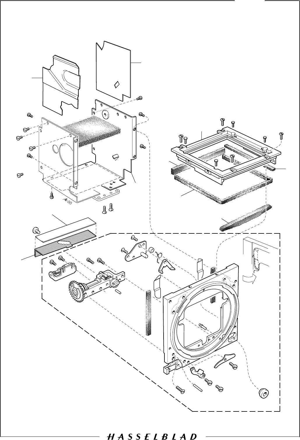
1 1 30 686 Bottom plate
2 1 30 375 Release bar
3 1 814 512 Spring
4 1 22 717 Signal arm
5 1 814 603 Spring
6 1 21095 Inner wall, right
7 1 817 119 Clip
8 6 820 014 Screw
9 1 13 356 Mirror catch
10 1 816 720 Spring
11 1 30 727 Cover
12 1 814 827 Spring
13 1 22 532 Rubber plug
14 1 13 280 Lens lock
15 1 13 362 Mirror lever
16 1 30 775 Spring
17 2 829 425 Screw
18 1 22 872 Reflection protector
19 1 22 813 Cover
-01
-01
BOD50307.EPS
960806
COPYRIGHT © 1996 ANDERS ENGSTRÖM
ANDERS ENGSTRÖM, ILLUSTRATÖR
Östra vägen 46
430 91 HÖNÖ
tel/fax 031- 96 84 64
anders@aeillustr.se
Camera body 503CW 13
October 1996
Revision 0
3
2
1
6
5
4
7
87
9
10
11
12
13

Description
Pos
No. Pcs Spare
Part No. Remark
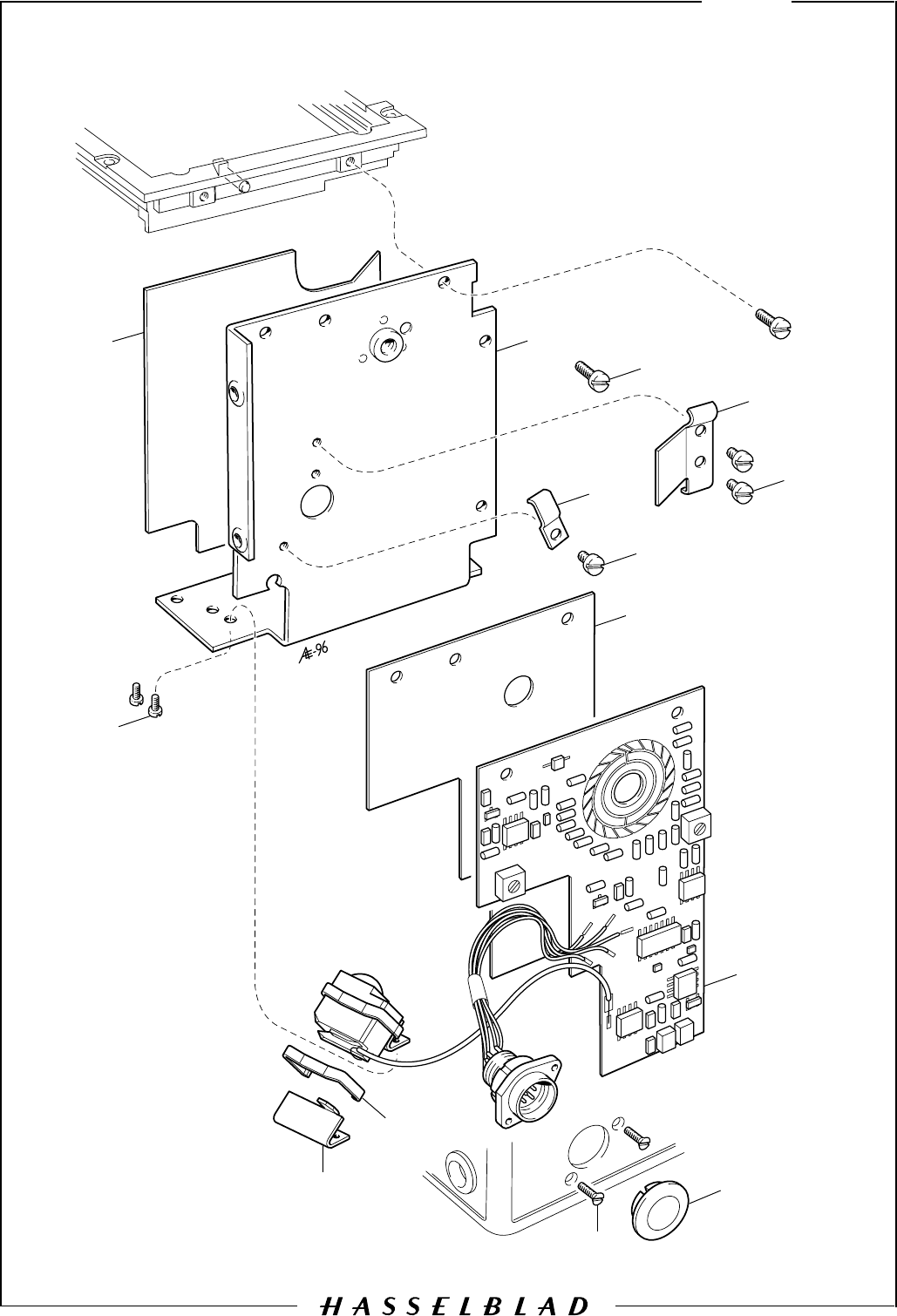
Camera body 503CW 13
May 2000
Revision 2
1 1 22 577 Clip
2 1 22576 Bracket
3 2 823 335 Screw
4 1 22 470 Socket cap
5 1 22 575 PC board See below
6 1 22 746 Insulating plate
7 3 820 011 Screw
8 1 12 453 Cable holder
9 1 22 453 Attachment
10 2 820 015 Screw
11 1 40 397 Inner wall, left
12 1 22 815 Reflection protector
13 2 820 325 Screw
22 882 PC board (incl. tape) From camera serial No. 19ER18271
22 879 Double-sided tape See Service Info 12/98
BOD50308.EPS
960710
COPYRIGHT © 1996 ANDERS ENGSTRÖM
ANDERS ENGSTRÖM, ILLUSTRATÖR
Östra vägen 46
430 91 HÖNÖ
tel/fax 031- 96 84 64
anders@aeillustr.se
14
Camera body 503CW
October 1996
Revision 0
1
2
3
4
5
6
7
8
9
11
10

Description
Pos
No. Pcs Spare
Part No. Remark
Camera body 503CW 14
October 1996Revision 0
1 2 103 517 Leather
2 1 815 904 Spring
3 1 815 707 Spring
4 1 103 516 Washer
5 1 103 113 Crank bayonet
6 1 107 409 Crank support
7 4 829 540 Screw
8 1 103 151 Crank arm
9 1 103 514 Slide
10 1 812 301 Pin
11 1 22 683 Rubber plug
BOD50101.EPS
970515
COPYRIGHT © 1997 ANDERS ENGSTR
Ö
M
ANDERS ENGSTRÖM, ILLUSTRATÖR
Östra vägen 46
430 91 HÖNÖ
tel/fax 031- 96 84 64
anders@aeillustr.se
15:1
May 1997
Camera body 501C
Revision 1
2
3
4
1

Description
Pos
No. Pcs Spare
Part No. Remark
Camera body 501C 15:1
October 1996Revision 0
1 1 40 384 Shell, complete
2 2 22 782 Name plate
3 1 103 592 Leather
4 1 103 529 Accessory rail
Spare parts not listed are the same as for 503CW
501CM02.EPS
970514
COPYRIGHT © 1997 ANDERS ENGSTRÖM
ANDERS ENGSTRÖM, ILLUSTRATÖR
Östra vägen 46
430 91 HÖNÖ
tel/fax 031- 96 84 64
anders@aeillustr.se
Camera body 501C 15:2
May 1997
Revision 1
4
3
2
5
1

Description
Pos
No. Pcs Spare
Part No. Remark
Camera body 501C 15:2
May 1997
Revision 1
Spare parts not listed are the same as for 503CW
1 1 13 355 Stop lever
2 1 22 799 Washer Alternatively none or 1 pc
3 1 412 401 Spacer
4 1 830 061 Screw
5 1 412 103 Coupling New type of winding crank from
camera serial No.17EU10379
BOD50102.EPS
961022
COPYRIGHT © 1996 ANDERS ENGSTRÖM
ANDERS ENGSTRÖM, ILLUSTRATÖR
Östra vägen 46
430 91 HÖNÖ
tel/fax 031- 96 84 64
anders@aeillustr.se
15:3
Camera body 501C
May 1997
Revision 1
1
23
4
5
6

Description
Pos
No. Pcs Spare
Part No. Remark
Camera body 501C 15:3
May 1997Revision 1
Spare parts not listed are the same as for 503CW
-3
1 1 30 519 Rear plate, complete State serial No.
2 2 20 958 Mirror assembly
3 1 20 901 Mirror protection
4 3 13 141 Foam plastic pad
5 1 20 854 Mirror
6 1 20 956 Frame
BOD50103.EPS
000530
COPYRIGHT ' 2000 ANDERS ENGSTR M
ANDERS ENGSTR M, ILLUSTRAT R
stra v gen 46
430 91 H N
tel/fax 031- 96 84 64
anders@aeillustr.se
15:4
Camera body 501C
May 2000Revision 3
1
2
3
4
5
6
7
8
9
10

Description
Pos
No. Pcs Spare
Part No. Remark
Camera body 501C 15:4
May 2000Revision 3
1 1 22 422 Foam plastic strip
2 1 20 959 Inner wall, left
3 1 22 580 Reflection protector
4 1 22 598 Cover
5 1 21 611 Frame, complete Incl. light seals
6 1 13 351 Foam plastic strip
7 1 13 211 Foam plastic strip
8 1 22 429 Foam plastic strip
9 1 22 873 Reflection protector
10 1 22 892 Cover Incl. reflection protector 22 873
Spare parts not listed are the same as for 503CW
-1

BOD50104.EPS
970512
COPYRIGHT © 1997 ANDERS ENGSTRÖM
ANDERS ENGSTRÖM, ILLUSTRATÖR
Östra vägen 46
430 91 HÖNÖ
tel/fax 031- 96 84 64
anders@aeillustr.se
Camera body 501C 15:5
May 1997Revision 1
1
2

Description
Pos
No. Pcs Spare
Part No. Remark
Camera body 501C 15:5
May 1997Revision 1
1 1 22 750 Coupling
2 1 22 751 Crank support
Spare parts not listed are the same as for 503CW
503CXi01.EPS
961029
COPYRIGHT © 1996 ANDERS ENGSTRÖM
ANDERS ENGSTRÖM, ILLUSTRATÖR
Östra vägen 46
430 91 HÖNÖ
tel/fax 031- 96 84 64
anders@aeillustr.se
Camera body 503CXi 16:1
October 1996
Revision 0
1

Description
Pos
No. Pcs Spare
Part No. Remark
Camera body 503CXi 16:1
October 1996
Revision 0
Spare parts not listed are the same as for 503CW
1 2 22 771 Name plate

BOD50102.EPS
961022
COPYRIGHT © 1996 ANDERS ENGSTRÖM
ANDERS ENGSTRÖM, ILLUSTRATÖR
Östra vägen 46
430 91 HÖNÖ
tel/fax 031- 96 84 64
anders@aeillustr.se
16:2
Camera body 503CXi
October 1996Revision 0
1
23
4
5
6

Description
Pos
No. Pcs Spare
Part No. Remark
Camera body 503CXi 16:2
October 1996
Revision 0
Spare parts not listed are the same as for 503CW
1 1 30 519 Rear plate, complete State serial No.
2 2 20 958 Mirror assembly
3 1 20 901 Mirror protection
4 3 13 141 Foam plastic pad
5 1 20 854 Mirror
6 1 20 956 Frame
503CXi03.EPS
000530
COPYRIGHT ' 2000 ANDERS ENGSTR M
ANDERS ENGSTR M, ILLUSTRAT R
stra v gen 46
430 91 H N
tel/fax 031- 96 84 64
anders@aeillustr.se
16:3
Camera body 503CXi
May 2000Revision 2
1
2
3
4
5
6
7
8
9
10

Description
Pos
No. Pcs Spare
Part No. Remark
Camera body 503CXi 16:3
May 2000
Revision 2
1 1 22 422 Foam plastic strip
2 1 20 959 Inner wall, left
3 1 22 580 Reflection protector
4 1 22 598 Cover
5 1 21 611 Frame, complete Incl. light seals
6 1 13 351 Foam plastic strip
7 1 13 211 Foam plastic strip
8 1 22 429 Foam plastic strip
9 1 22 873 Reflection protector
10 1 22 876 Cover Incl. reflection protector 22 873
Spare parts not listed are the same as for 503CW
-01
503CX01.EPS
961029
COPYRIGHT © 1996 ANDERS ENGSTRÖM
ANDERS ENGSTRÖM, ILLUSTRATÖR
Östra vägen 46
430 91 HÖNÖ
tel/fax 031- 96 84 64
anders@aeillustr.se
17:1
Camera body 503CX
October 1996
Revision 0
9
1
2
3
45
7
8
10
11
12
13
14
17
16
15
18
16
6

Description
Pos
No. Pcs Spare
Part No. Remark
Camera body 503CX 17:1
October 1996Revision 0
1 1 40 346 Shell, complete (chrome) Part No. 40347 (black)
2 1 103 506 Leather
3 1 103 327 Support
4 1 103 503 Leather
5 1 20 948 Socket
6 1 13 418 Plate spring
7 1 13 417 T-arm
8 1 816 759 Spring
9 1 821 206 Screw
10 1 13 134 Release button
11 1 22 367 Buffer
12 1 13 137 Screw
13 2 22 608 Name plate
14 1 103 846 Tripod socket 1/4" Standard
1 402 347 Tripod socket 3/8" Optional
15 2 824 701 Screw
16 8 823 735 Screw
17 2 823 781 Screw
18 1 103 349 Slide
Spare parts not listed are the same as for 503CW
503CX02.EPS
961025
COPYRIGHT © 1996 ANDERS ENGSTRÖM
ANDERS ENGSTRÖM, ILLUSTRATÖR
Östra vägen 46
430 91 HÖNÖ
tel/fax 031- 96 84 64
anders@aeillustr.se
Camera body 503CX 17:2
October 1996
Revision 0
12
3
4

Description
Pos
No. Pcs Spare
Part No. Remark
Camera body 503CX 17:2
October 1996
Revision 0
Spare parts not listed are the same as for 503CW
1 1 821 806 Screw
2 1 13 436 Locking washer
3 1 13 163 Bayonet plate
4 1 13 360 Shim, 0.2 mm For adjustment 13360-01, 0.4 mm

BOD50102.EPS
961022
COPYRIGHT © 1996 ANDERS ENGSTRÖM
ANDERS ENGSTRÖM, ILLUSTRATÖR
Östra vägen 46
430 91 HÖNÖ
tel/fax 031- 96 84 64
anders@aeillustr.se
17:3
Camera body 503CX
October 1996
Revision 0
1
23
4
5
6

Description
Pos
No. Pcs Spare
Part No. Remark
Camera body 503CX 17:3
October 1996
Revision 0
Spare parts not listed are the same as for 503CW
1 1 30 519 Rear plate, complete State serial No.
2 2 20 958 Mirror assembly
3 1 20 901 Mirror protection
4 3 13 141 Foam plastic pad
5 1 20 854 Mirror
6 1 20 956 Frame
503CX03.EPS
000530
COPYRIGHT ' 2000 ANDERS ENGSTR M
ANDERS ENGSTR M, ILLUSTRAT R
stra v gen 46
430 91 H N
tel/fax 031- 96 84 64
anders@aeillustr.se
17:4
Camera body 503CX
May 2000
Revision 2
1
2
3
4
5
6
7
8
11
9
10

Description
Pos
No. Pcs Spare
Part No. Remark
Camera body 503CX 17:4
May 2000Revision 2
1 1 22 422 Foam plastic strip
2 1 20 959 Inner wall, left
3 1 22 580 Reflection protector
4 1 22 598 Cover
5 1 21 611 Frame, complete Incl. light seals
6 1 13 351 Foam plastic strip
7 1 13 211 Foam plastic strip
8 1 22 429 Foam plastic strip
9 1 22 873 Reflection protector
10 1 22 876 Cover Incl. reflection protector 22 873
11 1 13 220 Signal arm Mounted on the right inner wall
Spare parts not listed are the same as for 503CW
-01
COPYRIGHT © 1994 ANDERS ENGSTRÖM
ANDERS ENGSTRÖM, ILLUSTRATÖR
Östra vägen 46
430 91 HÖNÖ TEL/FAX 031-96 84 64
503CX04.EPS
961031
Camera body 503CX 17:5
October 1996
Revision 0
1
Mounted on the
mechanism plate
1
2
3
5
4
6
7
8
9

Description
Pos
No. Pcs Spare
Part No. Remark
Camera body 503CX 17:5
October 1996Revision 0
1 1 402 411 Catch
2 1 402 412 Spring
3 1 402 414 Bayonet plate
4 4 824 602 Screw
5 1 402 321 Crank support
6 1 815 856 Spring
7 1 402 413 Button
8 1 14 221 Leather
9 1 13 355 Stop lever Mounted on the mechanism plate
Spare parts not listed are the same as for 503CW
500CM01.EPS
961029
COPYRIGHT © 1996 ANDERS ENGSTRÖM
ANDERS ENGSTRÖM, ILLUSTRATÖR
Östra vägen 46
430 91 HÖNÖ
tel/fax 031- 96 84 64
anders@aeillustr.se
18:1
Camera body 500C/M (Classic)
October 1996
Revision 0
9
12
3
45
76
8
10
11
12
13
14
15
16
17
20
19
18
21
19

Description
Pos
No. Pcs Spare
Part No. Remark
Camera body 500C/M (Classic) 18:1
October 1996Revision 0
1 1 40 309 Shell, complete (chrome) Part No. 40308 (black)
2 1 103 506 Leather
3 1 103 327 Support
4 1 103 503 Leather
5 1 20 948 Socket
6 1 13 418 Plate spring
7 1 13 417 T-arm
8 1 816 759 Spring
9 1 821 206 Screw
10 1 13 134 Release button
11 1 22 367 Buffer
12 1 13 137 Screw
13 1 103 511 Leather
14 1 103 592 Leather
15 1 103 529 Accessory rail
16 1 14 188 Name plate
402 347 Tripod socket 3/8" Standard
17 1 103 846 Tripod socket 1/4" Optional
1
18 2 824 701 Screw
19 8 823 735 Screw
20 2 823 781 Screw
21 1 103 349 Slide
Spare parts not listed are the same as for 503CW

503CX02.EPS
961025
COPYRIGHT © 1996 ANDERS ENGSTRÖM
ANDERS ENGSTRÖM, ILLUSTRATÖR
Östra vägen 46
430 91 HÖNÖ
tel/fax 031- 96 84 64
anders@aeillustr.se
Camera body 500C/M (Classic) 18:2
October 1996
Revision 0
12
3
4

Description
Pos
No. Pcs Spare
Part No. Remark
Camera body 500C/M (Classic) 18:2
October 1996
Revision 0
Spare parts not listed are the same as for 503CW
1 1 821 806 Screw
2 1 13 436 Locking washer
3 1 13 163 Bayonet plate
4 1 13 360 Shim, 0.2 mm For adjustment 13360-01, 0.4 mm

BOD50102.EPS
961022
COPYRIGHT © 1996 ANDERS ENGSTRÖM
ANDERS ENGSTRÖM, ILLUSTRATÖR
Östra vägen 46
430 91 HÖNÖ
tel/fax 031- 96 84 64
anders@aeillustr.se
18:3
Camera body 500C/M (Classic)
October 1996Revision 0
1
23
4
5
6

Description
Pos
No. Pcs Spare
Part No. Remark
Camera body 500C/M (Classic) 18:3
October 1996
Revision 0
Spare parts not listed are the same as for 503CW
1 1 30 519 Rear plate, complete State serial No.
2 2 20 958 Mirror assembly
3 1 20 901 Mirror protection
4 3 13 141 Foam plastic pad
5 1 20 854 Mirror
6 1 20 956 Frame
500CM02.EPS
000530
COPYRIGHT ' 2000 ANDERS ENGSTR M
ANDERS ENGSTR M, ILLUSTRAT R
stra v gen 46
430 91 H N
tel/fax 031- 96 84 64
anders@aeillustr.se
18:4
Camera body 500C/M (Classic)
May 2000Revision 2
1
2
3
4
5
6
7
8
11
9
10

Description
Pos
No. Pcs Spare
Part No. Remark
18:4
Camera body 500C/M (Classic)
May 2000
Revision 2
Spare parts not listed are the same as for 503CW
-01
1 1 22 422 Foam plastic strip
2 1 20 959 Inner wall, left
3 1 22 580 Reflection protector
4 1 22 598 Cover
5 1 21 611 Frame, complete Incl. light seals
6 1 13 351 Foam plastic strip
7 1 13 211 Foam plastic strip
8 1 22 429 Foam plastic strip
9 1 22 873 Reflection protector
10 1 22 892 Cover Incl. reflection protector 22 873
11 1 13 220 Signal arm Mounted on the right inner wall

COPYRIGHT © 1994 ANDERS ENGSTRÖM
ANDERS ENGSTRÖM, ILLUSTRATÖR
Östra vägen 46
430 91 HÖNÖ TEL/FAX 031-96 84 64
503CX04.EPS
961031
Camera body 500C/M (Classic) 18:5
October 1996
Revision 0
1
Mounted on the
mechanism plate
1
2
3
5
4
6
7
8
9

Description
Pos
No. Pcs Spare
Part No. Remark
Camera body 500C/M (Classic) 18:5
January 2001Revision 1
1 1 402 411 Catch
2 1 402 412 Spring
3 1 402 414 Bayonet plate
4 4 824 602 Screw
5 1 402 321 Crank support
6 1 815 856 Spring
7 1 402 413 Button
8 1 14 221 Leather
9 1 13 355 Stop lever Mounted on the mechanism plate
Spare parts not listed are the same as for 503CW

501CM01.EPS
970513
COPYRIGHT © 1997 ANDERS ENGSTRÖM
ANDERS ENGSTRÖM, ILLUSTRATÖR
Östra vägen 46
430 91 HÖNÖ
tel/fax 031- 96 84 64
anders@aeillustr.se
May 1997
19:1
Camera body 501CM
Revision 0
2
3
4
1

Description
Pos
No. Pcs Spare
Part No. Remark
Camera body 501CM 19:1
October 1997Revision 1
Spare parts not listed are the same as for 503CW
1 1 40 407 Shell, complete (Chrome) Part No. 40408 (black)
2 2 22 862 Name plate
3 1 103 592 Leather
4 1 103 529 Accessory rail
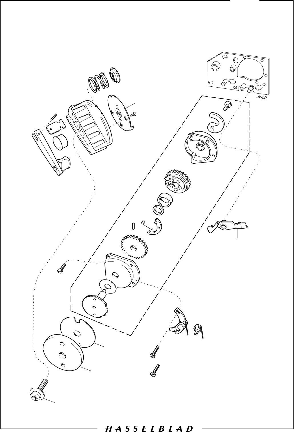
501CM02.EP
00050
9
COPYRIGHT
ANDERS ENGSTR
430 91 H
tel/fax 031-
anders@aeillustr.se
Camera body 501CM 19:2
May 2000
Revision 1
4
3
2
5
1

Description
Pos
No. Pcs Spare
Part No. Remark
Camera body 501CM 19:2
May 1997
Revision 0
Spare parts not listed are the same as for 503CW
1 1 13 355 Stop lever
2 1 22 799 Washer Alternatively none or 1 pc
3 1 412 401 Spacer
4 1 830 061 Screw
5 1 412 103 Coupling
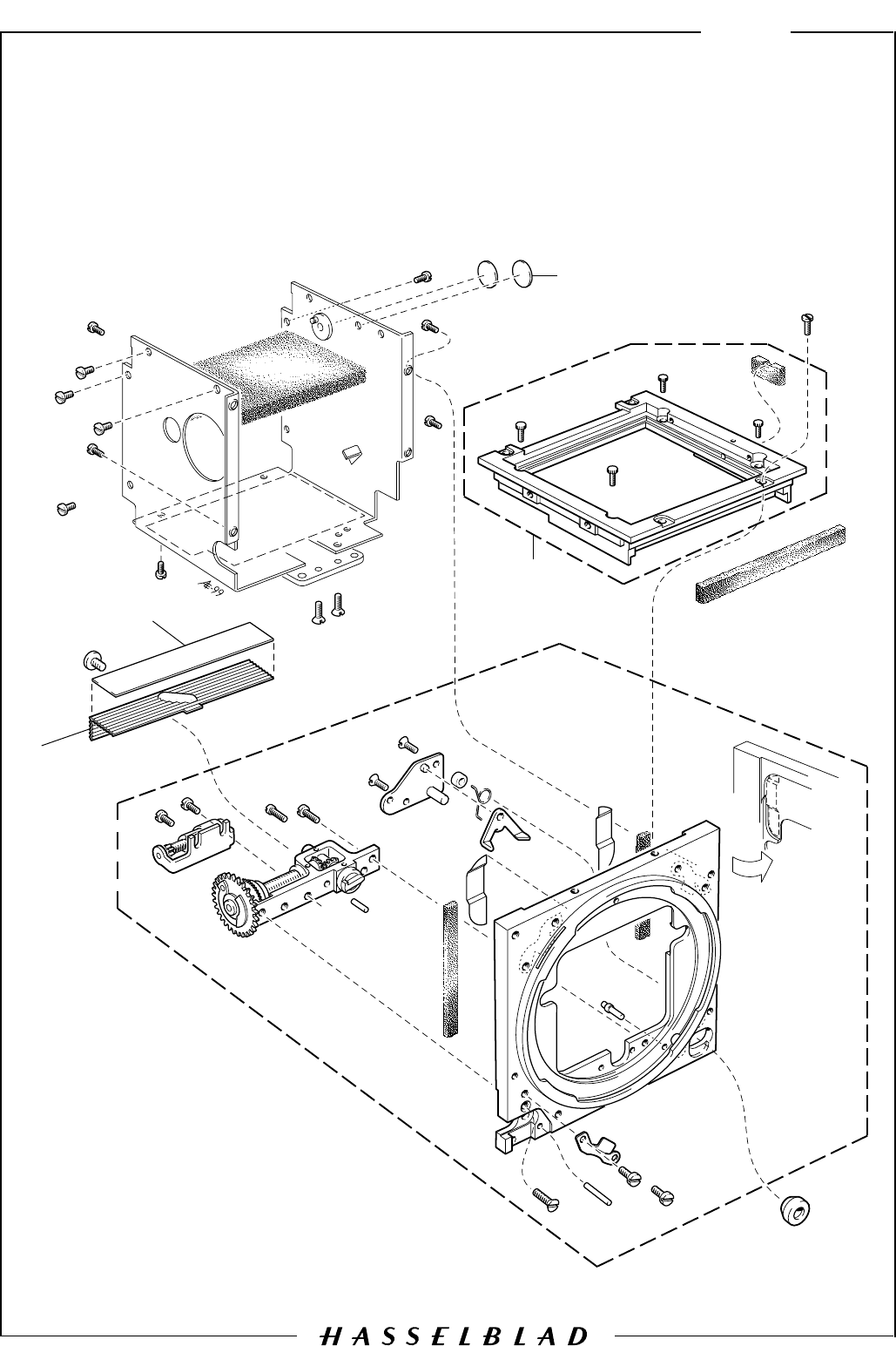
501CM03.EPS
990906
COPYRIGHT © 1999 ANDERS ENGSTRÖM
ANDERS ENGSTRÖM, ILLUSTRATÖR
Östra vägen 46
430 91 HÖNÖ
tel/fax 031- 96 84 64
anders@aeillustr.se
September 1999
Camera body 501CM 19:3
Revision 1
2
1
3
4

Description
Pos
No. Pcs Spare
Part No. Remark
Camera body 501CM 19:3
September 1999Revision 1
Spare parts not listed are the same as for 503CW
1 2 22 865 Light shield
2 1 22 806 Frame, complete
3 1 22 873 Reflection protector
4 1 22 892 Cover Incl. reflection protector 22 873
