Hawking Technologies HOD45B Hi-Gain Outdoor Dual-Band Wireless-N Access Point/Bridge User Manual HawkingTech HOD45B
Hawking Technologies, Inc. Hi-Gain Outdoor Dual-Band Wireless-N Access Point/Bridge HawkingTech HOD45B
UserManual.wiki
>
Hawking Technologies
>
HOD45B User Manual
user manual
Navigation menu
Upload a User Manual
Namespaces
Wiki Guide
HTML
PDF
Info
Views
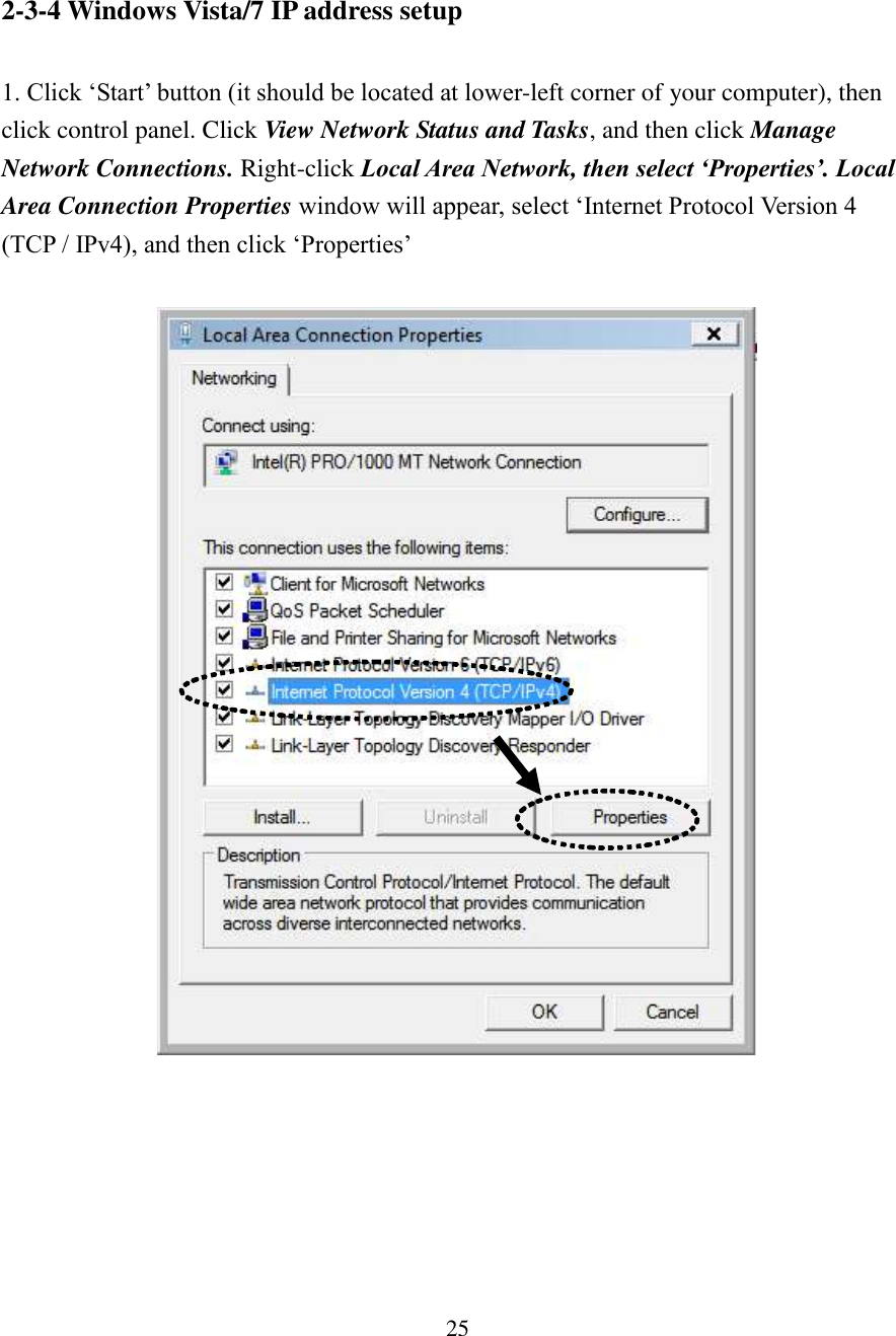
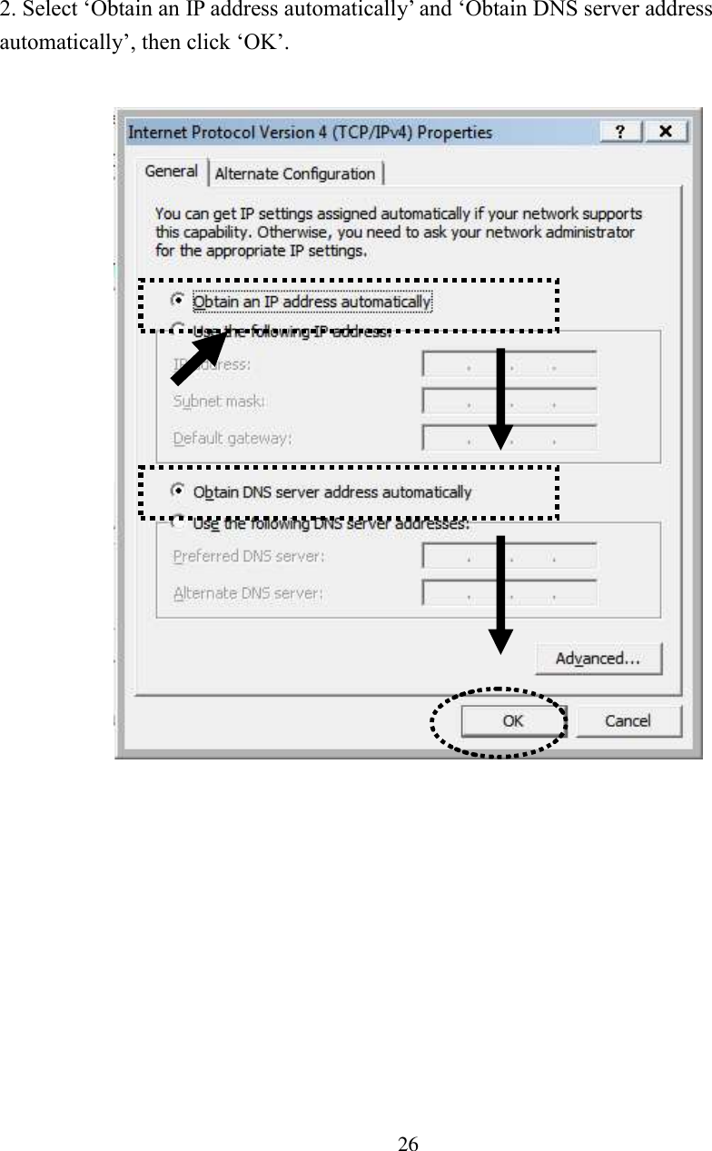
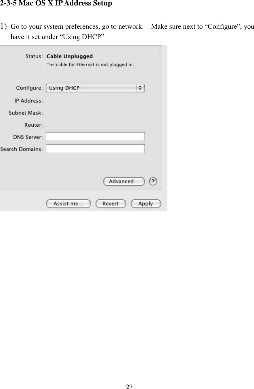
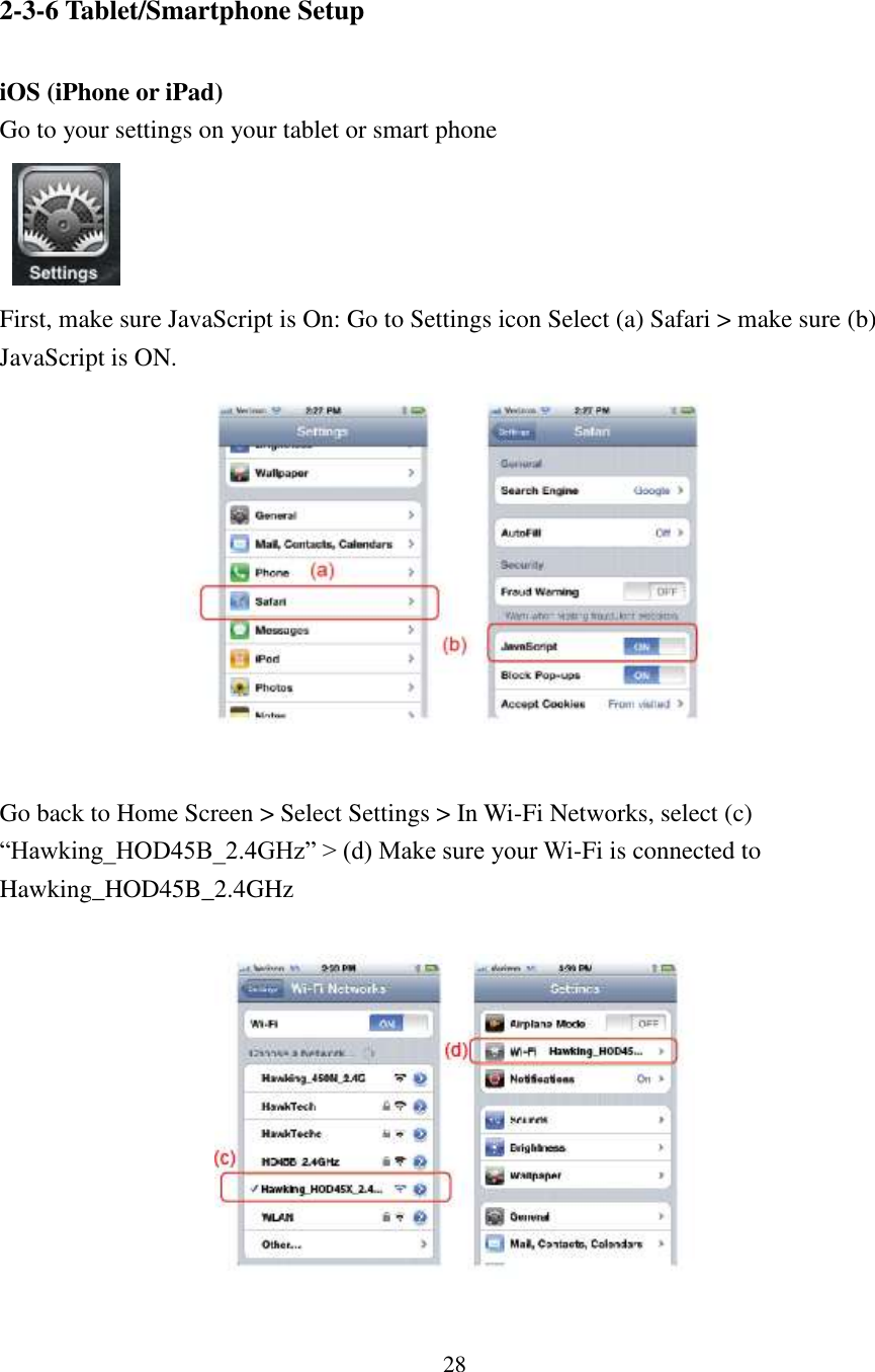
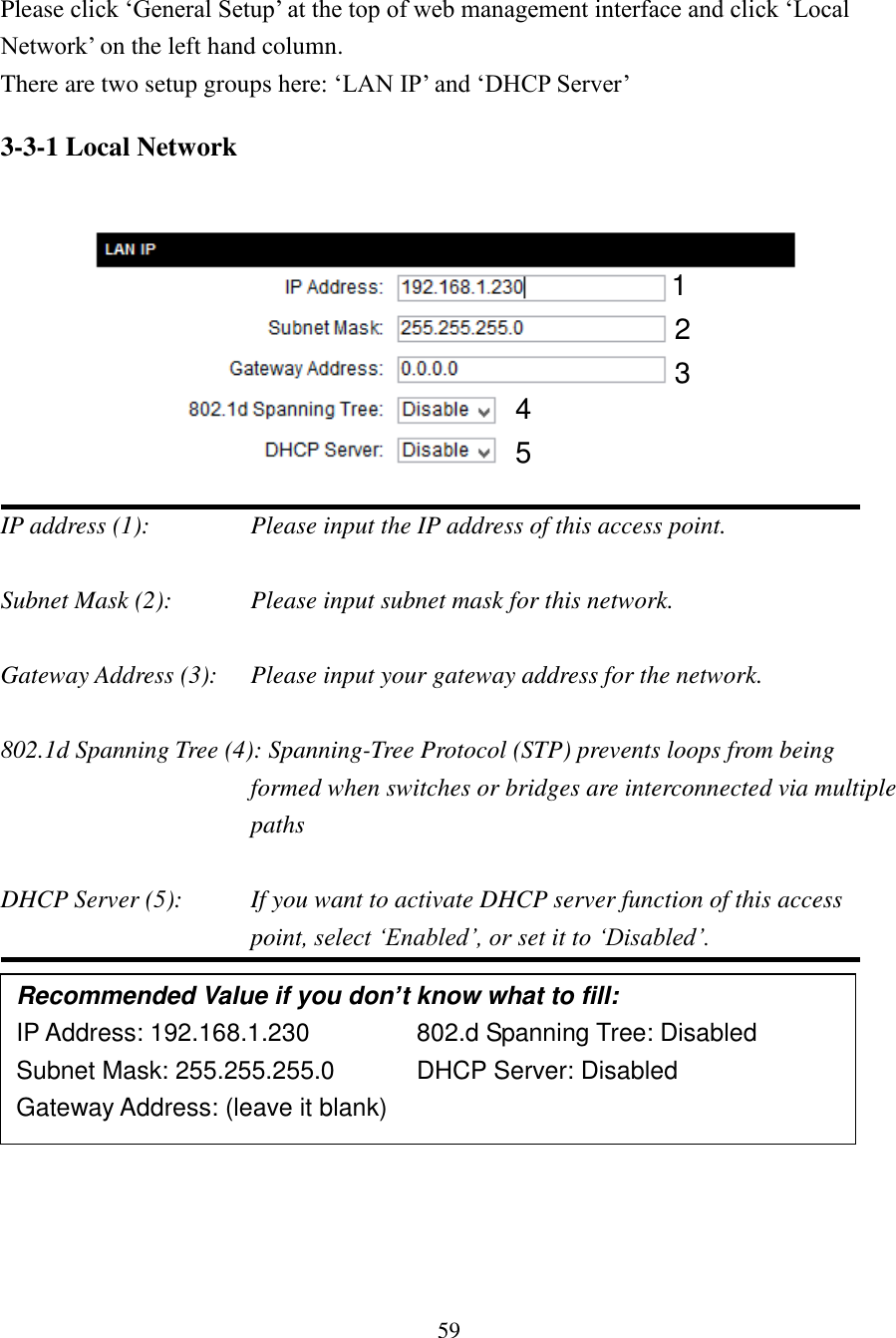
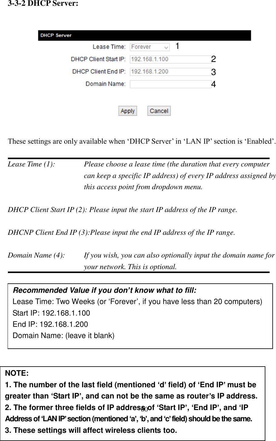
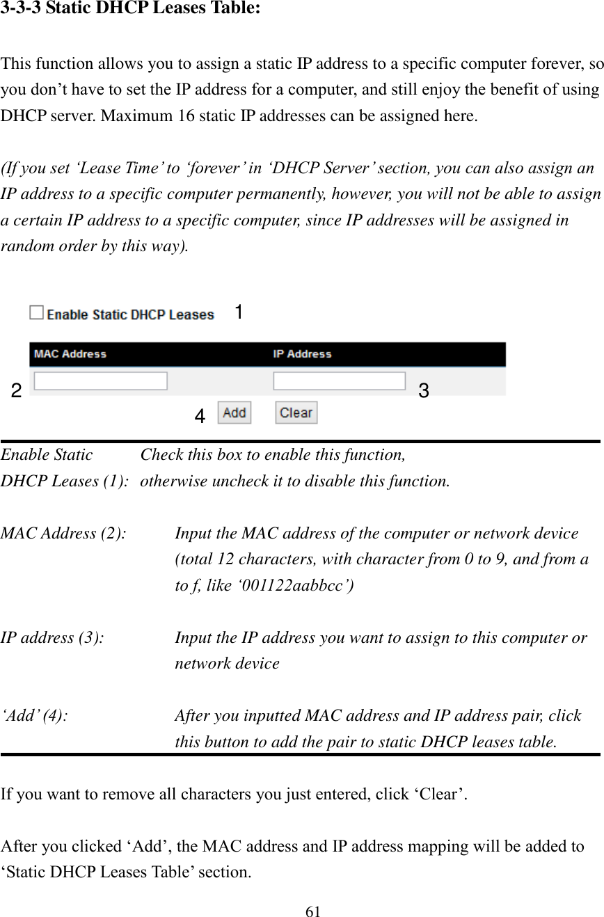
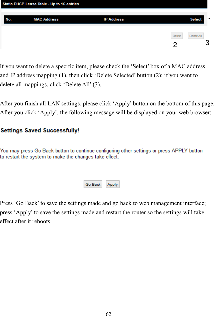
User Manual
Discussion / Help
Navigation