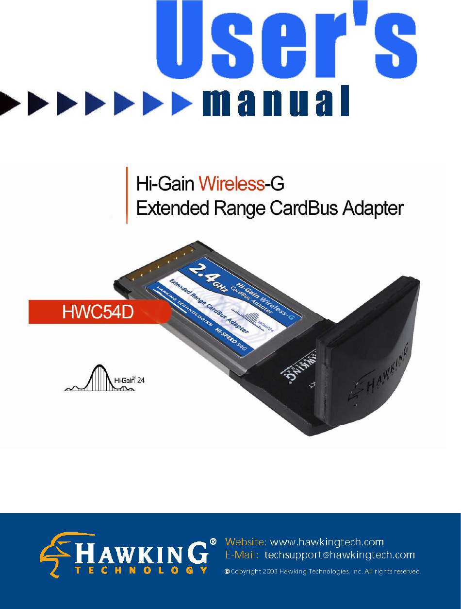
Hawking Technologies HWC54D00000 Hi-Gain Wireless-G Extended Range CarBus Adapter User Manual HWC54D Manual

Hawking Technologies, Inc. Hi-Gain Wireless-G Extended Range CarBus Adapter HWC54D Manual

User Manual

  Federal Communication Commission Interference Statement  This equipment has been tested and found to comply with the limits for a Class B digital device, pursuant to Part 15 of FCC Rules.    These limits are designed to provide reasonable protection against harmful interference in a residential installation. This equipment generates, uses, and can radiate radio frequency energy and, if not installed and used in accordance with the instructions, may cause harmful interference to radio communications.    However, there is no guarantee that interference will not occur in a particular installation. If this equipment does cause harmful interference to radio or television reception, which can be determined by turning the equipment off and on, the user is encouraged to try to correct the interference by one or more of the following measures:      1.  Reorient or relocate the receiving antenna. 2.  Increase the separation between the equipment and receiver. 3.  Connect the equipment into an outlet on a circuit different from that to which the receiver is connected. 4.  Consult the dealer or an experienced radio technician for help.  FCC Caution  This device and its antenna must not be co-located or operating in conjunction with any other antenna or transmitter.  This device complies with Part 15 of the FCC Rules. Operation is subject to the following two conditions: (1) this device may not cause harmful interference, and (2) this device must accept any interference received, including interference that may cause undesired operation.   Any changes or modifications not expressly approved by the party responsible for compliance could void the authority to operate equipment.  Federal Communications Commission (FCC) Radiation Exposure Statement  This equipment complies with FCC radiation exposure set forth for an uncontrolled environment. In order to avoid the possibility of exceeding the FCC radio frequency exposure limits, human proximity to the antenna shall not be less than 2.5cm (1 inch) during normal operation.
  Federal Communications Commission (FCC) RF Exposure Requirements  SAR compliance has been established in the laptop computer(s) configurations with PCMCIA slot on the side near the center, as tested in the application for Certification, and can be used in laptop computer(s) with substantially similar physical dimensions, construction, and electrical and RF characteristics. Use in other devices such a PDAs or lappads is not authorized. This transmitter is restricted for use with the specific antenna(s) tested in the application for Certification. The antenna(s) used for this transmitter must not be co-located or operating in conjunction with any other antenna or transmitter.  R&TTE Compliance Statement  This equipment complies with all the requirements of DIRECTIVE 1999/5/EC OF THE EUROPEAN PARLIAMENT AND THE COUNCIL of March 9, 1999 on radio equipment and telecommunication terminal Equipment and the mutual recognition of their conformity (R&TTE) The R&TTE Directive repeals and replaces in the directive 98/13/EEC (Telecommunications Terminal Equipment and Satellite Earth Station Equipment) As of April 8, 2000.  Safety  This equipment is designed with the utmost care for the safety of those who install and use it. However, special attention must be paid to the dangers of electric shock and static electricity when working with electrical equipment. All guidelines of this and of the computer manufacture must therefore be allowed at all times to ensure the safe use of the equipment.
   Trademarks & Copyright   Windows 95/98/ME and Windows NT/2000/XP are registered trademarks of Microsoft Corp. All other brands and product names are trademarks of their respective companies. No part of this publication may be reproduced in any form or by any means or used to make any derivative (such as translation, transformation or adaptation) without the express written consent of the manufacturer as stipulated by the United States Copyright Act of 1976.  FCC Warning This equipment has been tested and found to comply with the regulations for a Class B digital device, pursuant to Part 15 of the FCC Rules. These limits are designed to provide reasonable protection against harmful interference when the equipment is operated in a commercial environment. This equipment generates, uses, and can radiate radio frequency energy and, if not installed and used in accordance with this user’s guide, may cause harmful interference to radio communications. Operation of this equipment in a residential area is likely to cause harmful interference, in which case the user will be required to correct the interference at his/her own expense.  CE Mark Warning This is a Class B product. In a domestic environment, this product may cause radio interference, in which case the user may be required to take adequate measures. HAWKING LIMITED WARRANTY Hawking Technology guarantees that every HWC54D Hi-Gain Wireless-G CardBus Card is free from physical defects in material and workmanship under normal use for two (2) years from the date of purchase.    If the product proves defective during this two-year warranty period, call Hawking Customer Service in order to obtain a Return Authorization number.    Warranty is for repair or replacement only.    Hawking Technology does not issue any refunds.    BE SURE TO HAVE YOUR PROOF OF PURCHASE. RETURN REQUESTS CAN NOT BE PROCESSED WITHOUT PROOF OF PURCHASE.    When returning a product, mark the Return Authorization number clearly on the outside of the package and include your original proof of purchase.  IN NO EVEN SHALL HAWKING TECHNOLOGY’S LIABILTY EXCEED THE PRICE PAID FOR THE PRODUCT FROM DIRECT, INDIRECT, SPECIAL, INCIDENTAL OR CONSEQUENTIAL DAMAGES RESULTING FROM THE USE OF THE PRODUCT, ITS ACCOMPANYING SOFTWARE OR ITS DOCUMENTATION.  Hawking Technology makes no warranty or representation, expressed, implied or statutory, with respect to its products or the contents or use of this documentation and all accompanying software, and specifically disclaims its quality, performance, merchantability, or fitness for any particular purpose.   Hawking Technology reserves the right to revise or updates its products, software, or documentation without obligation to notify any individual or entity.    Please direct all inquiries to:techsupport@hawkingtech.com
 CONTENTS  1 INTRODUCTION............................................................................. 1 1.1 Features......................................................................................................................... 1 1.2 Specifications................................................................................................................ 1 1.3 Package Contents.......................................................................................................... 2 2 INSTALLATION PROCEDURE ..................................................... 3 3 CONFIGURATION UTILITY ......................................................... 6 3.1 Site Survey.................................................................................................................... 6 3.2 Profile............................................................................................................................ 7 3.2.1 Configure the Profile ................................................................................................ 8 3.2.2 Enable WPA in Windows XP ...................................................................................12 3.3  Link Status (Obtaining an optimal Wireless Connection) .......................................... 14 3.4 Statistics ...................................................................................................................... 17 3.5 Advance ...................................................................................................................... 17 3.6 About........................................................................................................................... 19 4 TROUBLESHOOTING .................................................................. 20
 1 1 Introduction  Thank you for purchasing the Hawking Technologies Hi-Gain 802.11g Wireless CardBus card. This card complies with the IEEE 802.11g standard, which supports up to 54Mbps high-speed wireless networking. It is also backwards compatible with IEEE 802.11b devices. The HWC54D is a high quality, high performance wireless product that has been designed with Hawking’s Hi-Gain Technology for improved distance and throughput.      For wireless security issues, this card supports 64/128-bit WEP data encryption that protects your wireless network from eavesdropping. It also supports the WPA (Wi-Fi Protected Access) security standard that combines IEEE 802.1x and TKIP (Temporal Key Integrity Protocol) technologies. Client users are required to authorize before accessing to APs or AP Routers, and the data transmitted in the network is encrypted/decrypted by a dynamically changed secret key. This card also has built-in an AES engine which ensure the highest degree of security and authenticity for digital information and it is the most advanced solution defined by IEEE 802.11i for security in wireless networks.  The power consumption of the card is also very low. Furthermore, this card provides several levels of power saving modes allowing the user to optimize the battery life of their notebooks.   1.1 Features • Works with both IEEE 802.11b and IEEE 802.11g products.   • Designed with Hawking Hi-Gain Technology   • Directional Hi-Gain Antenna for increased Wireless Distance and elimination of wireless interference from laptop components • High-speed transfer data rate - up to 54Mbps.   • High throughput allows for the transfer of data heavy multi-media files.   • Supports 64/128-bit WEP, WPA (TKIP with IEEE 802.1x) and AES functions for the highest level of security.   • Automatic fallback increases data security and reliability.   • Supports the most popular operating systems: Windows 98SE/Me/2000/XP. • Supports the 32-bit Cardbus interface.   1.2 Specifications • Standard: IEEE 802.11b/g • Interface: 32-bit Cardbus • Frequency Band: 2.4000 ~ 2.4835GHz (Industrial Scientific Medical Band)   • Modulation: OFDM with BPSK, QPSK, 16QAM, 64QAM (11g) BPSK, QPSK, CCK (11b) • Data Rate: 54/48/36/24/18/12/11/9/6/5.5/2/1Mbps auto fallback
 2 • Security: 64/128-bit WEP Data Encryption, WPA, AES and IEEE 802.1x  • Antenna: Hi-Gain 6dBi Patch Antenna (Fold-Up and Swivel)   • Drivers: Windows 98SE/Me/2000/XP • LEDs: TX/RX, Link • Transmit Power: 16dBm~18dBm (Before Antenna) • Power consumption: Tx: 350mA, Rx: 250mA   • Receive Sensitivity: 54Mbps OFDM, 10% PER, -70dBm, 11Mbps CCK, 8% PER, -86dBm,   1Mbps BPSK, 8% PER, -92dBm • Dimension: 8(H) x 118(W) x 54(D) mm • Temperature: 32~131°F (0 ~55°C)  • Humidity: Max. 95% (NonCondensing) • Certification: FCC, CE   1.3 Package Contents Before you begin the installation, please check the items of your package. The package should include the following items: • One Hi-Gain Wireless-G PC Card • One CD (Driver/Utility/User’s Manual.) • One Quick Installation Guide  If any of the above items is missing, contact your supplier as soon as possible.
 3 2 Installation Procedure  Before you proceed with the installation, please notice following descriptions. Note1: Please do not install the card into your laptop computer before installing the software program from the CD. Note2: The following installation was operated under Windows XP.    (Procedures are similar for Windows 98SE/Me/2000.) Note3: If you have installed the Wireless PC Card driver & utility before, please uninstall the old version first. A. Insert the Installation CD into your CD-ROM Drive. Execute the “setup” program.  B. Click “Easy Install” or “Next” to continue.  C. The system will begin to install the software utility for the HWC54D. Follow the instruction of the program to plug in the PC card into the Cardbus slot of your laptop computer.
 4             D. The system will automatically detect the card and display the Windows “Hardware Installation” screen. Click “Continue Anyway” to proceed with the installation.  E. The current setting of the “Country Channel” of the card is displayed for your reference. If you are in different country, please change the “Country Channel” from the drop-down menu and click “Next”.
 5  F.  Click “Finish” to complete the installation.     G. The “RaConfig” utility is displayed and you can start to configure the card to connect to your wireless network.
 6 3 Configuration Utility  The Configuration Utility is a powerful application that helps you configure the HWC54D and monitor the link status and statistics of your wireless connection. The Configuration Utility appears as an icon on the system tray of your Windows operating system while the card is running. You can open it by double-clicking on the icon.    You may also “Right-click” the icon, which will bring up the following options: z Lauch Config Utilities Select “Lauch Config Utilities” to open the Configuration Utility tool. z Exit Select “Exit” to close the Configuration Utility tool.   3.1 Site Survey When you open the Configuration Utility, the system will scan all wireless channels to find all access points/stations within the accessible range of your card and automatically connect to the wireless device with the highest signal strength. When using the “Site Survey” option, all nearby networks will be listed. You can change your connection to another network or you may add one of the networks to your own profile list.
 7 Parameter Description Available Networks  This list shows all available wireless networks within range of your card. It also displays the information of the networks including the SSID, BSSID, Signal Strength, Channel, Encryption, Authentication and Network Type. If you want to connect to any networks on the list, double-click the item on the list, and the card will automatically connect to the selected network.   Rescan Button  Click “Rescan” button to collect the information of all the wireless networks nearby.   Connect Button  Click “Connect” to connect to the selected network.   Add to Profile Button  Add the selected network to Profiles list.   3.2 Profile The “Profiles List” is for you to manage the networks you connect to frequently. You are able to Add/Delete/Edit/Activate a profile.    Parameter Description Profiles List  The profiles list display all the profiles and the relative information including Profile Name, SSID, Channel, etc.   Add/Delete/Edit Button  Click these buttons to add/delete/edit the selected profiles.   Activate Button  Click “Activate” to connect to the selected profile.
 8 3.2.1  Configure the Profile   System Configuration Parameter Description Profile Name  Define a recognizable profile name for you to identify the different networks.   SSID  The SSID (up to 32 printable ASCII characters) is the unique name identified in a WLAN. The ID prevents the unintentional merging of two co-located WLANs.    You may specify a SSID for the card and then only the device with the same SSID can interconnect to the card. If you want to add one of the networks nearby to the profile list, pull down the menu, all the networks nearby will be listed and you can add one of them to the profile list.   Power Saving Mode  The power saving function is only available when the network type is in Infrastructure. CAM(Constantly Awake Mode) – The card will always set in active mode.  Power Saving Mode – Enable the card in the power saving mode when it is idle.  CAM When AC Power – Select this option to automatically switch the card from power saving mode to CAM mode while the power of your laptop computer is supplied by the AC power but not battery.
 9 Parameter Description Network Type  Infrastructure – This operation mode requires the presence of an 802.11 Access Point. All communication is done via the Access Point or Router.    Ad-Hoc – Select this mode if you want to connect to another wireless station in the Wireless LAN network without going through an Access Point or Router.    Peer to Peer.   Transmit Power  If you wish to lower the transmit power of the card to save the power of your system, you can select the lower percentages from the list.   11B Preamble Type  The preamble defines the length of the CRC block for communication among wireless stations. This option is only active in the Ad Hoc network.  There are two modes including Auto and Long Preamble. If “Auto“ mode is selected, the card will auto switch the preamble mode depending on the wireless stations which the card is connecting to.   RTS Threshold  Minimum packet size required for an RTS (Request To Send). Forpackets smaller than this threshold, an RTS is not sent and the packet is transmitted directly to the wireless network. Select a setting within a range of 0 to 2312 bytes. Minor change is recommended.   Fragment Threshold  The value defines the maximum size of packets; any packet size larger than the value will be fragmented. If you have decreased this value and experience high packet error rates, you can increase it again, but it will likely decrease overall network performance. Select a setting within a range of 256 to 2312 bytes. Minor change is recommended.   Channel  This setting is only available for Ad Hoc mode. Select the number of the radio channel used for the networking. The channel setting should be the same with the network you are connecting to.
 10   Authentication vs. Security Parameter Description Authentication Type  This setting has to be consistent with the wireless networks that the card intends to connect to.   All security keys within a network must match to allow successful communications. None – No authentication is needed among the wireless network. Shared – Only wireless stations using a shared key (WEP Key identified) are allowed to connecting each other.    WPA-PSK –It is a special mode designed for home and small business users who do not have access to network authentication servers. In this mode, known as Pre-Shared Key, the user manually enters the starting password in their access point or gateway, as well as in each wireless stations in the network. WPA takes over automatically from that point, keeping unauthorized users that don't have the matching password from joining the network, while encrypting the data traveling between authorized devices. The encryption methods are including TKIP and AES. Note that this option is only available for Windows XP.
 11  Parameter Description Encryption Mode  None – Disable the WEP Data Encryption.  WEP – Enable the WEP Data Encryption. When the item is selected, you have to continue setting the WEP Encryption keys. TKIP – TKIP (Temporal Key Integrity Protocol) changes the temporal key every 10,000 packets (a packet is a kind of message transmitted over a network.) This insures much greater security than the standard WEP security.  AES – AES has been developed to ensure the highest degree of security and authenticity for digital information and it is the most advanced solution defined by IEEE 802.11i for the security in the wireless network.  Note: All devices in the network should use the same encryption method to ensure the communication.   WPA Pre-Shared Key  The WPA-PSK key can be from eight to 64 characters and can be letters or numbers. This same key must be used on all of the wireless stations in the network.   WEP Key (Key1 ~ Key4) The WEP keys are used to encrypt data transmitted in the wireless network. There are two types of key length: 64-bit and 128-bit. Select the default encryption key from Key 1 to Key 4 by selected the radio button.  Fill the text box by following the rules below. 64-bit – Input 10-digit Hex values (in the “A-F”, “a-f” and “0-9” range) or 5-digit ASCII characters (including “a-z” and “0-9”) as the encryption keys. For example: “0123456aef“ or “test1”.  128-bit – Input 26-digit Hex values (in the “A-F”, “a-f” and “0-9” range) or 13-digit ASCII characters (including “a-z” and “0-9”) as the encryption keys. For example: “01234567890123456789abcdef“ or “administrator”.
 12  3.2.2  Enable WPA in Windows XP Wi-Fi Protected Access (WPA) is a specification of standards-based, interoperable security enhancement that strongly increases the level of data protection (encryption) and access control (authentication) for existing and future wireless LAN systems. The technical components of WPA include Temporal Key Integrity Protocol (TKIP) for dynamic key exchange, and 802.1x for authentication.  There are two types of WPA security: WPA-PSK (no server) and WPA (with server). WPA requires a Radius Server to complete authentication among wireless stations and Access Points. Typically, this mode is used in an enterprise environment. WPA-PSK uses a so-called pre-shared key as the security key. A pre-shared key is a password that every wireless station must use to access the network. Typically, this mode will be used in a home environment.    To enable the WPA function in Windows XP, the following software systems are required: 1.  Windows XP Service Pack 1 with Windows XP Support Patch for Wi-Fi Protected Access program in addition. 2.  Configure the card using Wireless built-in utility (Wireless Zero Configuration).  z Note: When using the Wireless Utility there are two function selections when you open the execute the program. You can select to use the XP’s built-in utility with full WPA function. If “Use XP Wireless Zero Configuration” is selected, you can only configure the advance setting or check the link status and statistics from the “RaConfig” utility.                      1. From here, right click the icon to select “View Available Wireless Networks”. 2. Press “Advanced” button from “Wireless Network Connection”.
 13         Note: Uncheck “Use Windows to Configure my wireless network settings”, the “RaConfig” utility will be enabled again.  Parameter Description Network Authentication  Open –No authentication is needed among the wireless network. Shared – Only wireless stations using a shared key (WEP Key identified) are allowed to connecting each other.  WPA – This mode is for enterprise with an authentication server (Radius Server), WPA-enabled access point, and a WPA-enabled client. Once WPA is enabled, all clients and access points on the network must be WPA-enabled in order to access the network.  WPA-PSK – It is a special mode designed for home and small business users who do not have access to network authentication servers. In this mode, known as Pre-Shared Key, the user manually enters the starting password in their access point or gateway, as well as in each PC on the wireless network. WPA takes over automatically from that point, keeping unauthorized users that don't have the matching password from joining the network, while encrypting the data traveling between authorized devices.     3. Press the “Configure” button to configure the WPA function for the current network.
 14  Parameter Description Data Encryption  WEP – In WPA or WPA-PSK mode, WEP is also able to be the encryption method for the transmission data.  TKIP – TKIP (Temporal Key Integrity Protocol) changes the temporal key every 10,000 packets (a packet is a kind of message transmitted over a network.) This insures much greater security than the standard WEP security.  AES – AES has been developed to ensure the highest degree of security and authenticity for digital information and it is the most advanced solution defined by IEEE 802.11i for the security in the wireless network.    Note: All devices in the network should use the same encryption method to ensure the communication.   3.3 Link Status From the “Link Status” option, you can view all the information of the network you are connecting to.   You can use this tool in while at the same time repositioning the Hi-Gain antenna to find the optimal location for antenna placement.        Parameter Description Status  Display the SSID and MAC ID of the network the card is connecting to.   Current Channel  Display the number of the radio channel and the frequency used for the networking.
 15    Parameter Description Current Tx Rate  Display the transmission rate of the network. The maximum transmission rate is 54Mbps.   Throughput (Kbits/sec)  Display the speed of data transmitted and received.   Link Quality  This bar indicates the quality of the link. The higher the percentage, the better the quality.   dBm  If you want to know the signal strength in the unit of dBm, select this check box.   Signal Strength  This bar shows the signal strength level. The higher percentage shown in the bar, the more radio signal been received by the card. This indicator helps to find the proper position of the wireless device for quality network operation.
 16  Reading the Link Status Page and Obtaining the Strongest Connection  The Link Status page gives you information regarding your current wireless channel, transmit rate (speed) and link/signal quality.    You will use this utility to figure out which antenna position results in the best performance and connection.     1)  First you must determine where the location of your Wireless Access Point is within your network.   2)  Position the directional antenna towards the location of the Access Point.     3) While viewing your Link Status utility, rotate the antenna clockwise and counter-clockwise slowly to figure out which position gives you the highest Link Quality and Signal Strength.    Once you have determined which position gives you the best signal, leave the antenna in that orientation.  4)  When you are not using the Hi-Gain CardBus Card, fold down the antenna to its original closed position to avoid damage when travelling.
 17  3.4 Statistics This option enables you to view the available statistic information with its Tx counts (Tx success, Tx error, RTS Success and RTS Failed), and its Rx counts (Rx success, Rx error). You may reset the counters by clicking ”Reset Counter”.           3.5 Advanced This option enables you to configure more advanced settings, for example: wireless mode, protection mode and etc.
 18   Parameter Description Wireless Mode  802.11 B/G mix – If you have a mix of 802.11b and 802.11g wireless stations in your network, it is recommended to setting the card to this mode. This mode is also the default setting.  802.11 B only – This card can be compatible with both 802.11g and 802.11b wireless stations. If there are only 802.11b wireless stations in the network, you can set the card to this mode.   Tx BURST  Tx Burst enables the card to deliver the better throughput in the same period and environment.   B/G Protection  If you have a mix of 802.11b and 802.11g wireless stations in the network, it is recommended that you enable the protection mechanism. This mechanism can decrease the rate of data collisions between 802.11b and 802.11g wireless stations. When the protection mode is enabled, the throughput of the card will be a little lower due to more complex data packets that must be transmitted. Auto – Based on the status of the network and automatically disable/enable protection mode.  On – Always enable the protection mode.  Off – Always disable the protection mode.   Parameter Description ADHOC_OFDM  When the network type is in Ad Hoc mode, that the card can only work in 11b data rate. It is defined by Wi-Fi organization. If you want to enable the data rate up to 54Mbps (11g), select
 19 “ADHOC_OFDM”.   Tx Rate  There are several options including Auto/1/2/5.5/11/6/9/12/18/24/36/48/54Mbps for you to select. When the “Auto” is selected, the device will choose the most suitable transmission rate automatically. The higher data rate you designated in the network, the shorter distance is allowed between the card and the wireless stations.  When the wireless mode is “802.11 B only”, the maximum data rate is 11Mbps (11b) so that there are only “Auto/1/2/5.5/11Mbps” options you can select.   Turn Off RF Button  If you want to turn off the radio of the card temporarily, click this button. To turn on the radio, click this button again.   3.6 About By choosing this option, you can click the hyperlink to connect to the website for the information of the wireless chipset vendor and review basic information about the Utility such as the Driver, Utility and EEPROM Version. The MAC Address of the card is displayed in the screen as well.
 20 4 Troubleshooting  This chapter provides solutions to problems usually encountered during the installation and operation of the adapter.    1.  What is the IEEE 802.11g standard? 802.11g is the new IEEE standard for high-speed wireless LAN communications that provides for up to 54 Mbps data rate in the 2.4 GHz band. 802.11g is quickly becoming the next mainstream wireless LAN technology for the home, office and public networks.   802.11g defines the use of the same OFDM modulation technique specified in IEEE 802.11a for the 5 GHz frequency band and applies it in the same 2.4 GHz frequency band as IEEE 802.11b. The 802.11g standard requires backward compatibility with 802.11b.  The standard specifically calls for:   A.  A new physical layer for the 802.11 Medium Access Control (MAC) in the 2.4 GHz frequency band, known as the extended rate PHY (ERP). The ERP adds OFDM as a mandatory new coding scheme for 6, 12 and 24 Mbps (mandatory speeds), and 18, 36, 48 and 54 Mbps (optional speeds). The ERP includes the modulation schemes found in 802.11b including CCK for 11 and 5.5 Mbps and Barker code modulation for 2 and 1 Mbps. B.  A protection mechanism called RTS/CTS that governs how 802.11g devices and 802.11b devices interoperate.  2.  What is the IEEE 802.11b standard? The IEEE 802.11b Wireless LAN standard subcommittee, which formulates the standard for the industry. The objective is to enable wireless LAN hardware from different manufactures to communicate.  3.  What does IEEE 802.11 feature support? The product supports the following IEEE 802.11 functions: z CSMA/CA plus Acknowledge Protocol z Multi-Channel Roaming z Automatic Rate Selection z RTS/CTS Feature z Fragmentation z Power Management  4. What is Ad-hoc? An Ad-hoc integrated wireless LAN is a group of computers, each has a Wireless LAN adapter, Connected as an independent wireless LAN. Ad hoc wireless LAN is applicable at a departmental scale for a branch or SOHO operation.  5.  What is Infrastructure? An integrated wireless and wireless and wired LAN is called an Infrastructure configuration. Infrastructure is applicable to enterprise scale for wireless access to central database, or wireless application for mobile workers.
 21  6.  What is BSS ID? A specific Ad hoc LAN is called a Basic Service Set (BSS). Computers in a BSS must be configured with the same BSS ID.  7.  What is WEP? WEP is Wired Equivalent Privacy, a data privacy mechanism based on a 40 bit shared key algorithm, as described in the IEEE 802 .11 standard.  8.  What is TKIP? TKIP is a quick-fix method to quickly overcome the inherent weaknesses in WEP security, especially the reuse of encryption keys. TKIP is involved in the IEEE 802.11i WLAN security standard, and the specification might be officially released by early 2003.  9. What is AES? AES (Advanced Encryption Standard), a chip-based security, has been developed to ensure the highest degree of security and authenticity for digital information, wherever and however communicated or stored, while making more efficient use of hardware and/or software than previous encryption standards. It is also included in IEEE 802.11i standard. Compare with AES, TKIP is a temporary protocol for replacing WEP security until manufacturers implement AES at the hardware level.  10.  Can Wireless products support printer sharing?  Wireless products perform the same function as LAN products. Therefore, Wireless products can work with Netware, Windows 2000, or other LAN operating systems to support printer or file sharing.  11.  Would the information be intercepted while transmitting on air? WLAN features two-fold protection in security. On the hardware side, as with Direct Sequence Spread Spectrum technology, it has the inherent security feature of scrambling. On the software side, WLAN series offer the encryption function (WEP) to enhance security and Access Control. Users can set it up depending upon their needs.  12.  What is DSSS?What is FHSS?And what are their differences? Frequency-hopping spread-spectrum (FHSS) uses a narrowband carrier that changes frequency in a pattern that is known to both transmitter and receiver. Properly synchronized, the net effect is to maintain a single logical channel. To an unintended receiver, FHSS appears to be short-duration impulse noise. Direct-sequence spread-spectrum (DSSS) generates a redundant bit pattern for each bit to be transmitted. This bit pattern is called a chip (or chipping code). The longer the chip is, the greater the probability that the original data can be recovered. Even if one or more bits in the chip are damaged during transmission, statistical techniques embedded in the radio can recover the original data without-the need for retransmission. To an unintended receiver, DSSS appears as low power wideband noise and is rejected (ignored) by most narrowband receivers.
 22  13.  What is Spread Spectrum? Spread Spectrum technology is a wideband radio frequency technique developed by the military for use in reliable, secure, mission-critical communication systems. It is designed to trade off bandwidth efficiency for reliability, integrity, and security. In other words, more bandwidth is consumed than in the case of narrowband transmission, but the trade off produces a signal that is, in effect, louder and thus easier to detect, provided that the receiver knows the parameters of the spread-spectrum signal being broadcast. If a receiver is not tuned to the right frequency, a spread –spectrum signal looks like background noise. There are two main alternatives, Direct Sequence Spread Spectrum (DSSS) and Frequency Hopping Spread Spectrum (FHSS).  14.  What is Hi-Gain and dBi?     Hi-Gain is Hawking Technologies high performance wireless distance extending product line.    It           encompasses a group of products and technologies used to help solve distance issues       accompanied with WiFi products.    A unit of measurement on antenna strength and power is dBi.         The higher the dBi or gain level of an antenna the more powerful it is.  15.    What is the difference between directional and omni-directional antennas?       Directional and omni-directional antennas determine the wireless output pattern of antennas.           In standard installations it is normally the wireless access point that uses the omni-directional         antenna (360 degree wireless output) while the clients (desktop or laptops) that use the         directional antennas (concentrated narrow wireless signal) to create a stronger link directly to      the access point.  16.    How do I get an Optimal Wireless Connection with the HWC54D?       If pointing the antenna directly at the access point is not providing a sufficient signal connection                 then you can try bouncing the signals off walls.    Wireless signals can reflect off walls or through               windows to get to their desired location so try different positions to find the best antenna         orientation for your network.

Navigation menu