Hawking Technologies HWU8DD HI-GAIN WIRELESS-G USB DISH ADAPTER User Manual HWU8DD Manual 1 26 05
Hawking Technologies, Inc. HI-GAIN WIRELESS-G USB DISH ADAPTER HWU8DD Manual 1 26 05
UserManual.wiki
>
Hawking Technologies
>
HWU8DD User Manual
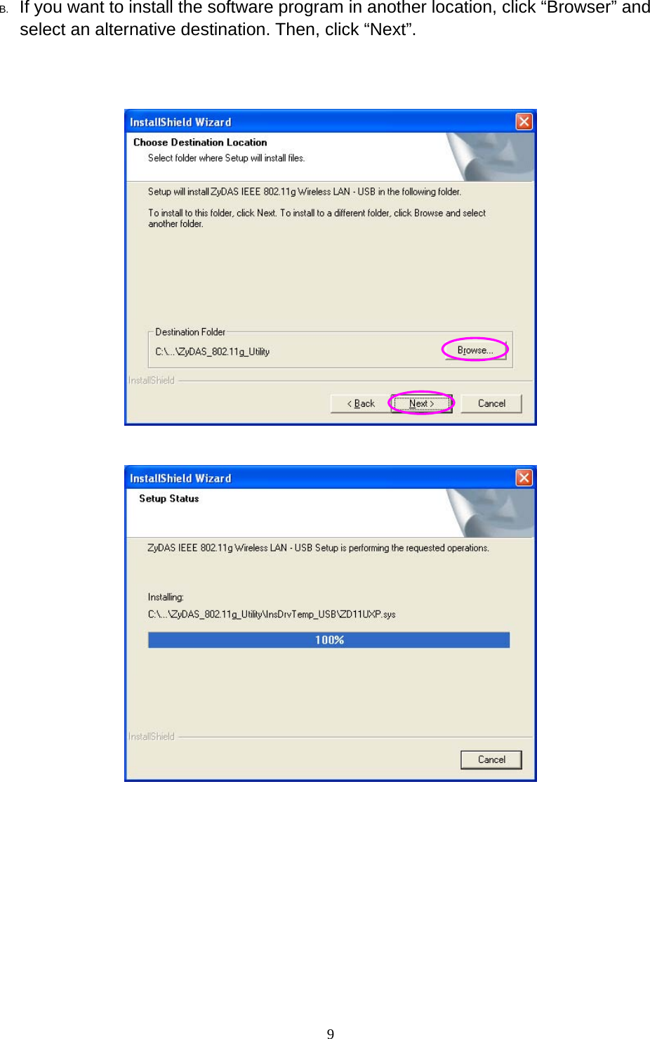
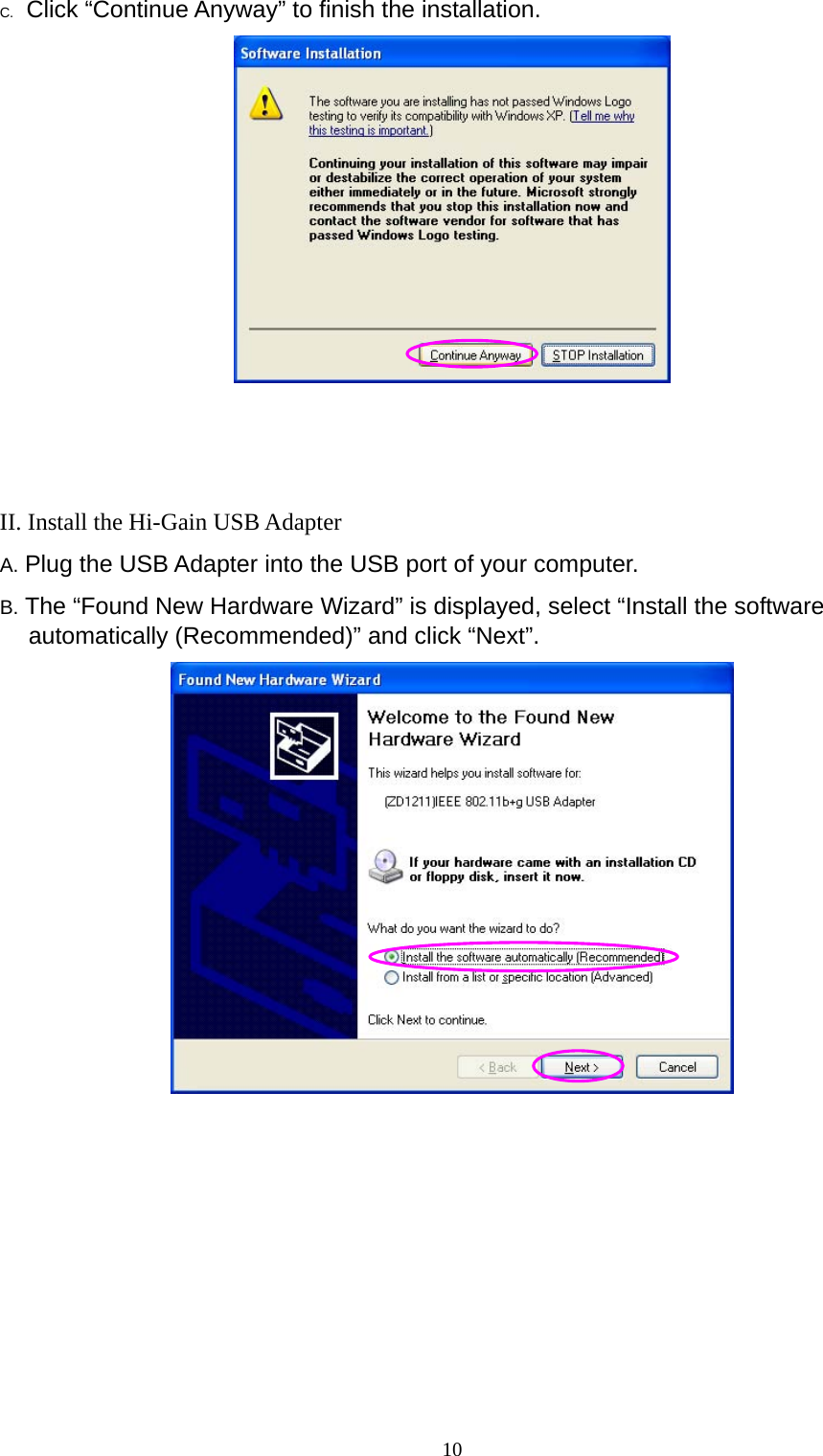
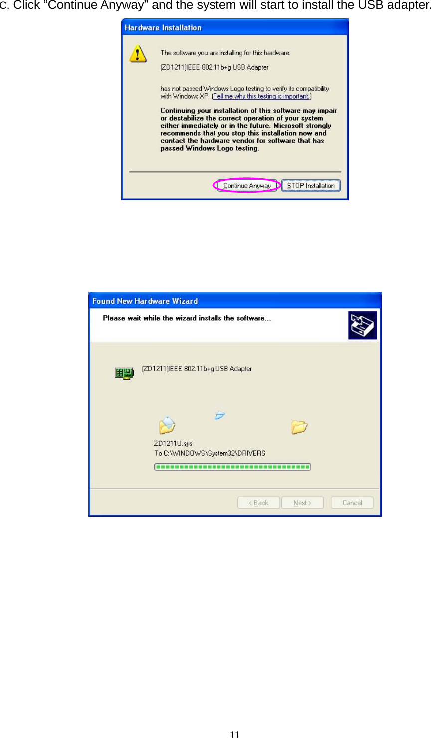
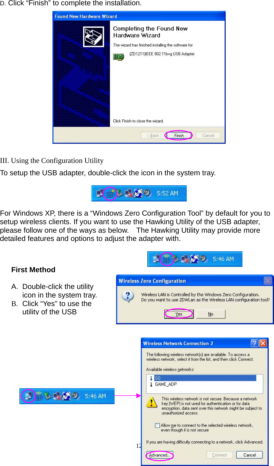
USERS MANUAL
Navigation menu
Upload a User Manual
Namespaces
Wiki Guide
HTML
PDF
Info
Views
User Manual
Discussion / Help
Navigation