Hayter Mowers Condor Hydrostatic Drive 510D Users Manual
!! Hayter-19 Hayter Lawn Mower Manuals - Lawn Mower Manuals – The Best Lawn Mower Manuals Collection
2015-02-09
: Hayter-Mowers Hayter-Mowers-Condor-Hydrostatic-Drive-510D-Users-Manual-564501 hayter-mowers-condor-hydrostatic-drive-510d-users-manual-564501 hayter-mowers pdf
Open the PDF directly: View PDF ![]() .
.
Page Count: 52

Part%No.%111*5824%Rev%A
CONDOR
HYDROSTATIC DRIVE
POWER%UNIT%Model%No:%510D%*%Serial%No.%from%312030001
ATTACHMENTS%*%Serial%No.%from%312030001:
Verge%Attachment%3%Blades%*%Code%214D
Verge%Attachment%5%Blades%*%Code%243D
Rotary%Attachment%30”%*%Code%212D
Operator’s Manual
Original Instructions (EN)
Date: 20.02.2012

ATTENTION
THIS SYMBOL MEANS
BE ALERT!
YOUR SAFETY IS INVOLVED
READ THIS MANUAL BEFORE USING THE CONDOR HYDROSTATIC
DRIVE MOWER.
IT IS ESSENTIAL THAT OPERATORS STUDY IT FOR THEIR OWN
SAFETY.
ALL OPERATORS SHOULD SEEK AND OBTAIN PROFESSIONAL AND
PRACTICAL INSTRUCTIONS ON THE SAFE USE OF THE MOWER.
THESE SERVICES ARE AVAILABLE THROUGH HAYTER APPROVED
COMMERCIAL DEALERS.

1.5 1.5
CONTENTS
CONTENTS Page No.
Safety Precautions 1.7 - 1.12
Training 1.7
Preparation 1.7 - 1.8
Operation 1.8 - 1.9
Maintenance and Storage 1.10
Decals 1.11 - 1.12
EC Conformity Information 1.13 - 1.14
Noise / Vibration Levels 1.13
EC Declaration of Conformity 1.14
Introduction 1.15
Specifications 1.16 - 1.18
Engine 1.16
Transmission System 1.16
Cutterhead Drive System 1.16
Power Unit 1.17
Operator Controls 1.17
Weight and Dimensions 1.17
Recommended Lubricants And Hydraulic Fluids 1.18
Verge Attachments 1.18
Rotary Attachments 1.18
Assembling The Mower 1.19 - 1.21
Assembling and Removing the Cutterhead Attachments - Introduction 1.19
Assembling the Cutterhead to the Power Unit 1.20 - 1.21
Operating The Mower 1.22 - 1.28
Safety Notice 1.22
Operator Presence Controls 1.22
Identification of Controls 1.23
Braking System 1.23
Throttle Control 1.23
Travel 1.23 - 1.24
Transmission Bypass Valve Control 1.24
Ignition Switch 1.25
Cutterhead Drive Operation 1.25
Starting the Engine 1.25 - 1.26
Stopping the Engine 1.26
General Operating Hints 1.27
Adjusting Height of Cutter 1.27 - 1.28
Handlebar Height Adjustment 1.28

1.6 1.6
CONTENTS
CONTENTS Page No.
MAINTENANCE 1.29 - 1.43
Maintenance 1.29
Engine 1.30
Running in period - at First 50 Hours of Use 1.30 - 1.31
Daily and before use 1.31 - 1.33
Every 50 hours 1.34
Every 200 hours 1.35 - 1.37
Rotary Attachment 1.41 - 1.42
Cutterblades 1.42
Preparing the Mower for Storage 1.43
GRASS CUTTING FAULTS - Both Types of Attachments 1.44
TROUBLE SHOOTING 1.45 - 1.46
ELECTRICAL CIRCUIT DIAGRAM 1.47
WARRANTY 1.48
NOTES 1.49 - 1.50
CUSTOMER INFORMATION 1.51

1.7 1.7
This manual should be regarded as part of the machine, as it gives essential
information regarding machine safety, operation, maintenance and specifications.
READ THIS MANUAL BEFORE USING THE CONDOR MOWER, IT IS
ESSENTIAL THAT OPERATORS STUDY IT FOR THEIR OWN SAFETY.
THE FOLLOWING PRECAUTIONS MUST BE TAKEN TO HELP PREVENT
ACCIDENTS. A CAREFUL OPERATOR WHO USES COMMON SENSE IS THE
SAFEST OPERATOR.
SAFETY PRECAUTIONS
Training
Read the instructions carefully. Be familiar with the controls and the proper use of the equipment. Learn how
to stop the mower quickly in an emergency.
Never allow children or people unfamiliar with these instructions to use the mower. Local regulations may
restrict the age of the operator.
Never mow while people, especially children, or pets are nearby.
Keep in mind that the operator or user is responsible for accidents or hazards occurring to other people or
their property.
All drivers should seek and obtain professional and practical instruction. Such instruction should
emphasise:
The need for care and concentration when working with this machine.
Preparation
Check that the machine complies with all applicable regulations, including those in force when used on the
public highway.
While mowing, always wear substantial footwear and long trousers. Do not operate the equipment when
barefoot or wearing open sandals. Eye protection should be worn.
Thoroughly inspect the area where the equipment is to be used and remove all objects which can be thrown
by the machine.
Replace faulty silencers.
Always ensure that the mower is in a safe operating condition. Frequently check all nuts, bolts and screws for
tightness. Use only genuine Hayter replacement parts.
Damaged cutterblades or loose fixing bolts are major hazards. Before use, always visually inspect the cutting
mechanism to ensure that there are in good condition. Damaged cutterblades must be replaced immediately
with genuine Hayter replacement parts. Unbalanced cutterblades may cause serious damage to your machine.
Refer to MAINTENANCE.
On attachment with twin cutterheads, take care as rotating one cutterblade will cause the other to rotate.

1.8 1.8
Preparation Continued
WARNING: Petrol is highly flammable.
- Store fuel in containers specifically designed for this purpose.
- Refuel outdoors only and do not smoke while refuelling.
- Add fuel before starting the engine. Never remove the cap from the fuel tank or add petrol whilst the
engine is running or when the engine is hot. Allow the engine to cool for at least two minutes before
refuelling.
- Do not attempt to start the engine if petrol is spilled or a smell of petrol is present. Move the mower
away from the area of spillage and avoid creating any source of ignition until petrol vapors have
dissipated.
- Always use fresh fuel. Stale fuel can block the carburettor and cause leakage.
- Replace fuel tank and oil tank caps securely.
Operation
Do not operate the engine in a confined space where dangerous carbon monoxide fumes can collect.
Mow only in daylight or in good artificial light.
Avoid using the mower on wet grass, where feasible.
Walk, never run.
Do not use on slopes of more than 20 degrees.
Always be sure of your footing on slopes and stay alert for humps, hollows and other hidden hazards.
Ground conditions may affect the ability of the operator to maintain safe footing. Particular conditions may
not permit safe operation on the slope limit stated.
Mow across the face of the slopes, never up and down.
Exercise extreme caution when changing direction on slopes.
Do not mow excessively steep slopes.
Use extreme caution when reversing or pulling the mower towards you.
Disengage the cutterhead drive if the mower has to be tilted for transportation when crossing surfaces other
than grass and when transporting the mower to and from the area to be mowed.
Never operate the mower unless the guards are securely in position and in good condition and all safety
devices are in place.
Do not change the engine governor settings or overspeed the engine. Operating an engine at excessive speed
may increase the hazard of personal injury.
Disengage the cutterhead and ground drive clutches before starting the engine.
SAFETY PRECAUTIONS

1.9 1.9
Operation Continued
Start the engine carefully, with feet well away from the cutting devices.
Do not tilt the mower when starting the engine.
Do not put hands or feet near or under rotating parts. Keep clear of discharge openings at all times.
Stop the engine, turn the ignition control to the ‘off’ position, set the parking brake and disconnect the spark
plug lead:
- Before clearing blockages or unclogging the discharge chute.
- Before cleaning/checking or working the mower.
- After striking a foreign object. Inspect the mower for damage and ensure necessary repairs are
made before re-starting.
- If the mower starts to vibrate abnormally (check immediately).
Stop the engine, turn the ignition control to the ‘off’ position, set the parking brake:
- Whenever you leave the mower.
- Before refuelling.
- Before making a height of cut adjustment.
Reduce throttle control setting during engine shutdown.
Turn off the fuel tap at the conclusion of mowing.
WARNING: The cutting devices can continue to rotate after the engine is switched off.
SAFETY PRECAUTIONS

1.10 1.10
SAFETY PRECAUTIONS
Maintenance and Storage
Keep all nuts, bolts, and screws tight to be sure the equipment is in safe working condition.
Allow the engine to cool before storing in any enclosure.
To reduce the risk of fire, keep the engine, silencer, fuel tank and battery compartment free of grass, leaves or
excessive grease.
Replace worn or damaged parts for safety.
Ensure that all safety decals are properly secured and in good condition.
If the fuel tank has to be drained, this should be done outdoors.
Be careful during adjustment of the machine to prevent entrapment of the fingers between moving blades and
fixed parts of the machine. On twin bladed cutterheads, take care as rotating one bottom plate will cause the
other to rotate.
Health & Safety
The Condor Mower has been designed and constructed so that, in so far as is reasonably practical,
they meet the safety requirements of the Machinery Directive 2006/42/EC, they will not endanger the
safety and health of those working with them. This is, however, subject to the machine being properly
used and maintained according to the conditions stated in this manual and elsewhere, which have been
found necessary as a result of the research and testing.
1.11 1.11
SAFETY PRECAUTIONS
Decals
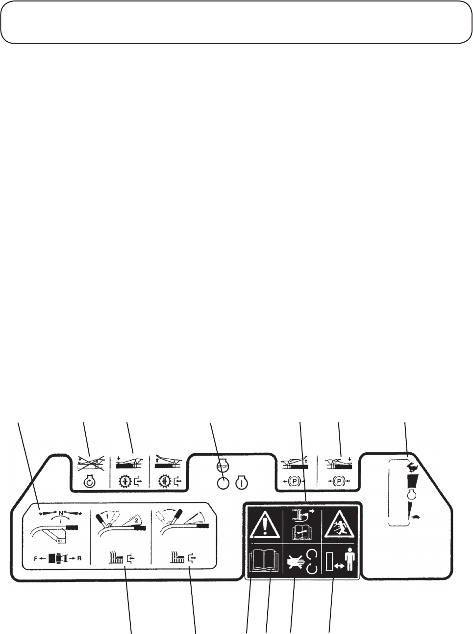
Decal - Control Panel
Part No: 510226 (2)
Location: Control Panel
A) Ground travel control: controls forward & reverse transmission speed
B) Bypass valve important: prevent damage - do not operate the bypass valve lever whilst the engine is
running as this will cause a rapid temperature rise in the bypass valve.
C) Hydrostatic unit bypass valve control - grip lever to close the bypass valve, grip lever to open bypass valve
release.
D) Engine stop/run switch
E) Stop engine and remove spark plug lead before performing maintenance or repair work.
F) Parking break - grip a latch lever to engage the parking brake. Unlatch and release lever to disengage the
parking brake.
G) Engine speed control - push the lever forward to increase engine speed, pull the lever back to reduce engine
speed
H) Engage cutterhead drive
I) Disengage cutterhead drive
J) WARNING: CAUTION - risk of danger/safety alert
K) Carefully read the operators manual before using the machine
L) Do not open or remove safety shields while the engine is running
M) Danger of being hit by thrown objects. Keep bystanders at a safe distance
A B C D E
H
F G
IJ K L M
12
1.12 1.12
SAFETY PRECAUTIONS
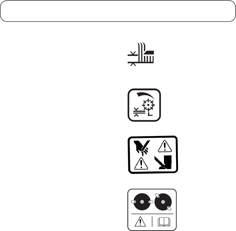
Decals continued
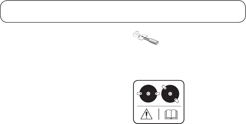
Decal - Cutting height adjustment
Part No: 320006 (3)
Location: R.H side of deck (212D)
Both sides of unit (214D, 243D)
Decal - Cylinder cut adjustment
Part No: 214053 (0)
Location: Top front of verge unit, both sides
Decal - Severing of hand of fingers
Part No: 40-13-010 (1)
Location: Both sides of the deck (212D)
R.H side of deck (214D)
R.H side of deck (243D)
Decal - Cutterhead timing
Part No: 111-3904 (A)
Location: Between gearboxes on the rotary attachment

1.13 1.13
EC CONFORMITY INFORMATION
Noise Levels
Operator Daily Personal Noise Exposure:
HAYTER LIMITED have no control over site
conditions, duration of use, state of maintenance or
adjustment of the mower. All of these factors will affect
the operator’s daily personal noise exposure level - LEP,d
Under typical working conditions operators could be
exposed to a daily personal noise exposure level in
excess of 80 dB (A) LEP,d
Sound pressure level:
The sound pressure level at the operator’s position is
87.5 dB (A) measured in accordance with European
Standard EN836.
Sound power level:
The guaranteed sound power level is 100 dB (A)
measured in accordance with EC Directive 2000/14/EC.
If hearing protection is required, ear protectors with good
attenuation in the 63 - 8000 Hz frequency range should
be used.
Employers of personnel using this machine should refer
to the 2003/10/EC Directive for minimum health and
safety requirements regarding exposure and risks to
physical agents (noise).
Vibration Levels
Operator Daily Personal Vibration Exposure:
HAYTER LIMITED have no control over site condi-
tions, duration of use, state of maintenance or adjustment
of the mower. All of these factors will affect the opera-
tor’s daily personal vibration exposure level.
Under certain working conditions the operator may be
exposed to vibration levels above those stated.
EC Declaration of Conformity
WARNING: Under no circumstances can attachments
other than those covered by the EC Declaration of
Conformity or other attachments that may be introduced
by Hayter Limited in the future, having a similar EC
Declaration of Conformity, be supplied for or fitted to
the Code 510D Condor Hydrostatic Drive Power Unit.
Unauthorised use of other equipment will invalidate the
EC Declaration of Conformity and may cause the mower
to be unsafe. The fitting of genuine ‘Hayter’ attachments
which fall outside the definition of ‘Machinery’ is per-
mitted and is the only exception to this rule.
100
dB
Code Serial No:
510D
310000001
CONDOR - HYDRO
POWER UNIT
kg: 135 RPM:2900 kW:
SPELLBROOK, BISHOP'S STORTFORD,
HERTS. CM23 4BU. ENGLAND.
2010
Wear Hearing
Protection

1.14 1.14
EC CONFORMITY INFORMATION
VIBRATION INFORMATION
Hand / Arm Vibration Level at the Operator Position measured in accordance with European Standard EN 836 & EN 1033:
Measured Vibration Level ahv =
Uncertainty of measurement K =
Whole Body Vibration Level at the Operator Seat measured in accordance with European Standard EN 836:
Measured Vibration Level aw =
Uncertainty of measurement K =
SOUND PRESSURE INFORMATION
Sound Pressure Level at the Operator Position measured in accordance with European Standard EN 836 & EN 11094:
Measured Sound Pressure Level LPA =
Uncertainty of measurement K =
ms-2
dB(A)
ms-2
dB(A)
ms-2
dB(A)
ms-2
dB(A)
ms-2
dB(A)
ms-2
dB(A)
EC DECLARATION OF CONFORMITY
Manufactured by: HAYTER LIMITED,
declare that thelawnmower :
Model name:
Type:
Model No:
Cutting width:
Speed of rotation of the
cutting device:
Complies with the provisions of Directive: 2006/42/EC Essential Health & Safety Requirements relating to the Design &
Construction of Machinery and Safety Components and the regulations transposed into national law.
Also Directive 2000/14/EC Noise emission in the environment by equipment for use outdoors, as amended and the regulations
Also Directive 2004/108/EC Electromagnetic Compatibility and the regulations transposed into national law.
transposed into national law.
Procedure applied for the conformity assessment: ANNEX VI, procedure 1.
Notified Body: Sound Research Laboratories Ltd, Holbrook House, Little Waldingfield, Sudbury, Suffolk. CO10 0TH
ENGLAND
Notified body identification No: 1088
Measured sound power level:
Guaranteed sound power level:
Authorised Signatory:
S.A Maryniak
(Technical Director)
Declaration done and technical documentation kept at:
HAYTER LIMITED
Spellbrook, Bishop’s Stortford,
Herts. CM23 4BU ENGLAND
Date: 12.04.10
Address: Spellbrook, Bishop s Stortford, Herts. CM23 4BU. ENGLAND
Serial No.
Speed of rotation of engine:
Attachment model no:
Cutting device model name:
Cutting width:
2.0
3.0
N/A
N/A
212
86
3
212
212
2.0
3.5
N/A
N/A
214
86
3
214
214
2.0
3.5
N/A
N/A
243
86
3
243
243
2800 rpm
99 dB(A)
100 dB(A)
99 dB(A)
100 dB(A)
99 dB(A)
100 dB(A)
Hydrostatic Power Unit
Pedestrian lawnmower
510
81 cm
2900 rpm
212
30" Rotary Attachment
76 cm
1230 rpm
214
30" Verge Attachment
76 cm
1230 rpm
243
30" Verge Attachment
76 cm
Condor
Hydrostatic Power Unit
Pedestrian lawnmower
510
81 cm
2900 rpm
Condor
Hydrostatic Power Unit
Pedestrian lawnmower
510
81 cm
2900 rpm
Condor

1.15 1.15
INTRODUCTION
Introduction
The Condor Hydrostatic System is a total grass cutting system designed for professional use. A range of optional
attachments are available which can be quickly interchanged.
This machine is designed solely for cutting grass and similar low lying ground vegetation within the limitations
stated in this manual. Use in any other way is considered as contrary to the intended use. Compliance with and
strict adherence to the conditions of operation, service and repair as specified in this Operator’s Manual also con-
stitute essential elements of the intended use.
This machine should be operated, serviced and repaired only by persons who are familiar with its particular char-
acteristics and who are acquainted with the relevant safety procedures.
The safety precautions listed herein together with all other generally recognised regulations on safety and all road
traffic regulations must be observed at all times.
Any arbitrary modifications carried out to this machine may relieve Hayter Limited of liability for any resulting
damage or injury.
The unit is petrol engine powered and has separate clutch controls for engaging the cutterhead and ground drives.
The Condor system is well balanced and incorporates a number of features for effortless safe mowing. The handle-
bar controls are ‘user friendly’ and incorporate an operator presence control system. This system will automati-
cally disengage the cutterhead and ground drive clutches when the operator releases the controls.
The Condor Hydrostatic Mower is a precision built machine designed for robust use, a high standard of finish and
long life. The way in which this mower is operated and maintained will have a profound effect on its performance
and reliability.
This manual contains advice on the safe operation of the Condor Hydrostatic Mower, which is offered for guid-
ance and protection of all those operating and servicing this machine.
In pursuit of continuous product development, Hayter Limited reserve the right to alter specifications without
notice.
Cutterhead Variants: The Condor Hydrostatic Drive Power Unit can be fitted with a range of cutterhead configura-
tions and optional extras:
30” Verge Attachment - 3 Blade
30” Verge Attachment - 5 Blade
30” Rotary Attachment
Optional Extras:
Narrow Wheel Kit.
Left and right: Throughout this manual the terms ‘left’ and ‘right’ refer to the machine when looking in the
direction of forward travel.

1.16 1.16
Specifications
ALL FIGURES ARE NOMINALLY QUOTED AT THE RATED ENGINE SPEED OF 2900 RPM
UNLESS OTHERWISE STATED.
Engine
Condor
Type: HONDA GX340 UT2
4 - stroke, overhead valve, 1 cylinder
Speed Rating: 2900 rpm (no load)
Power Rating: 6.5 kw (8.7 hp) @ 2900 rpm
Capacity: 337 cc
Air Cleaner: Dual element type.
Cooling System: Forced air
Oil Type: SAE 10W-30
Oil Capacity: 1.1 Litres
Fuel Type: Unleaded petrol
Fuel Capacity: 6.1 Litres
IMPORTANT - PREVENT DAMAGE: For further information regarding the engine, refer to the Engine
Manual.
Transmission System
Drive Type: Hydraulic static differential transaxle
Cutterhead Drive System
Power Unit Intermediate Drive: Single clutch V-belt drive with integral engine lockout switch sensor
Power Unit Final Drive: Twin V-belt via countershaft
Verge Drive: Triple V-belt via countershaft
Rotary Attachment: Swinging cutterblades attached to circular bottom plates on coupled gearboxes
with pulley brake.
SPECIFICATIONS

1.17 1.17
Power Unit Specifications
Ground Speed: 0 - 9 km/hr (0 - 5.6 mph) forward
0 - 5 km/hr (0 - 3 mph) reverse
Tyres Tyre Type Recommended max.
tyre pressures
Standard 16 x 6.5 - 8 4 Ply 1.9 bar (28 psi)
Option 16 x 4.00 x 8 4 ply 2.2 bar (32 psi)
Parking Brake: Lever operated integral transaxle disc brake
Safety Features: Neutral start interlock
Operator presence control
Braked cutterhead drive (rotary attachment)
Operator Controls
Cutterhead drive: Hand operated lever to engage
(Maintain by twin hand-operator pressure control levers)
Engine Speed: Hand operated lever
Parking Brake: Hand operated lever with engagement lock
Forward and Reverse: Forward and reverse twin hand operator hand/thumb levers
Ignition: On/Off switch
Bypass Valve: Hand operated lever
Weight and Dimensions
30” Rotary attachment fitted 30” Verge attachment fitted
Maximum Working Width: 844 mm 902 mm
Maximum Mowing Width: 762 mm 762 mm
Maximum Overall Length: 2040 mm 1680 mm
Overall Height: 1160 mm 1160 mm
Approx. Working Weight: 195 kg
135 kg (Power unit only)
218 kg (5 blade)
135 kg (Power unit only)
SPECIFICATIONS

1.18 1.18
Recommended Lubricants and Hydraulic Fluids
Grease Points: A good quality medium grease
Cutterhead gearbox (rotary): SAE90
Engine: SAE10W-30
Hydrostatic Unit: BP Vanellus M20W, BP Energol HLP22 or equivalent
Transaxle: SAE EP90 Transmission Oil
Should you be in any doubt please contact your Hayter Limited dealer. Using incorrect grades will cause prema-
ture wear of hydraulic components and invalidate warranty.
Verge Attachments
Code 214D Code 243D
Cylinder Drive: V-Belt/Countershaft V-Belt/Countershaft
Cutting Width: 762 mm 762 mm
Cylinder Diameter: 190 mm 190 mm
Cylinder Speed: 1250 rpm 1250 rpm
Height of Cut: 17 mm (0.7˝) to 62 mm (2.4˝) 17 mm (0.7˝) to 62 mm (2.4˝)
Number of Blades: 3 5
Smooth Rear Roller: Standard Standard
Rotary Attachments
Code 212D
Drive: V-Belt/Gearbox
Cutting Width: 762 mm
Type of Blade: 2 disc with swinging blades
Cutterbar Speed: 2860 rpm
Height of Cut: 20 mm (0.8˝) to 55 mm (2.2˝)
Number of Blades: 4 (2 on each disc)
SPECIFICATIONS

1.19 1.19
Assembling and Removing the Cutterhead Attachments - Introduction
The Condor Hydrostatic Drive Power Unit Code 510D is designed to be used with either the 30” Rotary
Cutterhead Attachment Code 212D or the 30” Verge Cutterhead Attachments Code 214D and 243D. Any of
these attachments can be quickly mounted to or removed from the power unit.
WARNING: PREVENT ACCIDENTS - Stop the engine, apply the parking brake and disconnect the
spark plug lead before attempting to remove or mount a cutterhead attachment.
WARNING: PREVENT ACCIDENTS - Do not attempt to carry out the following procedure by your-
self, another person must assist you.
Power unit with 30” Rotary Cutterhead Attachment.
ASSEMBLING THE MOWER
1.20 1.20
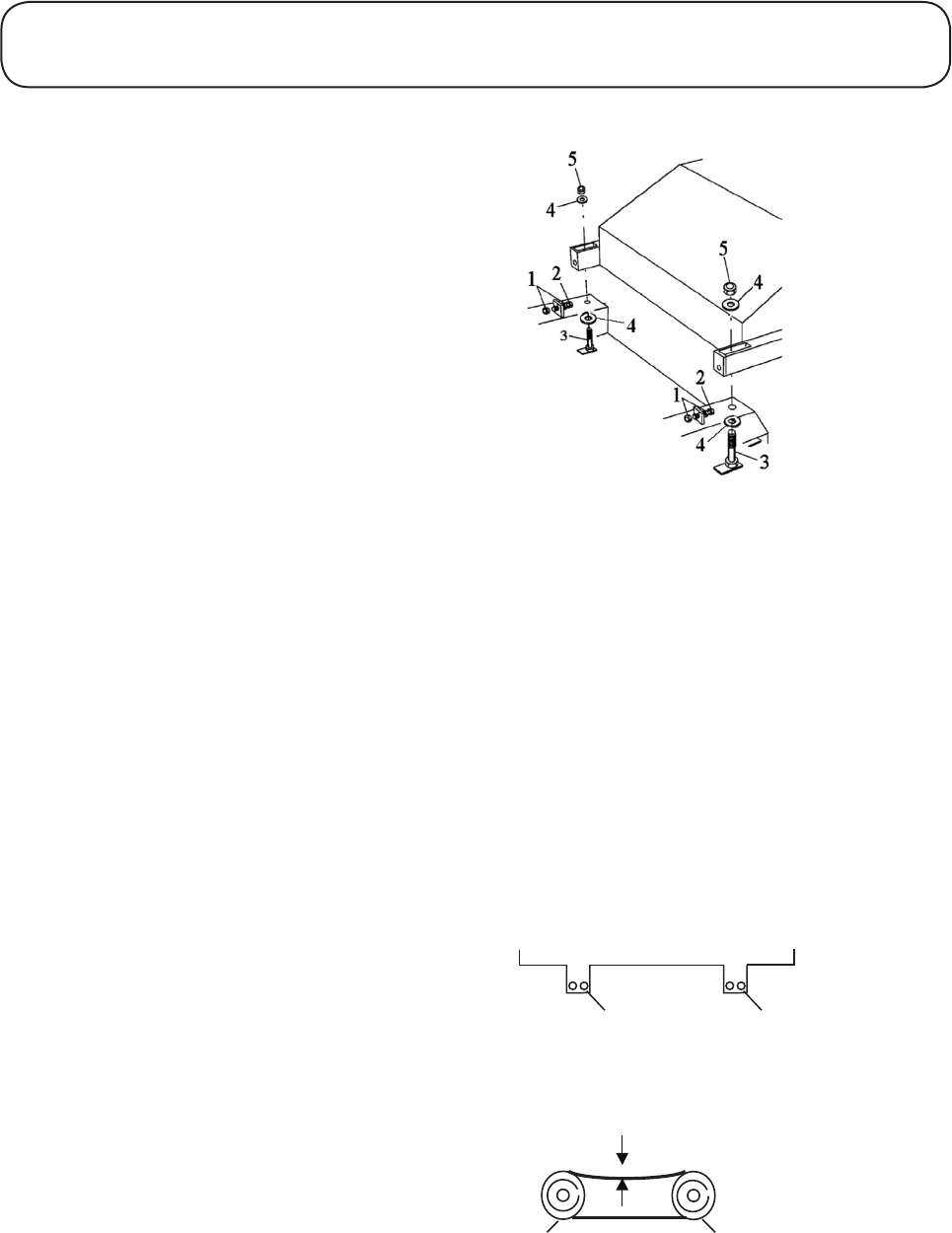
Assembling the Cutterhead Attachment
to the Power Unit
1. Position the cutterhead attachment on level
ground.
2. Remove the cutterhead drive cover.
3. Remove the power unit transmission guard.
4. Remove the engine drive belt from the
countershaft pulley.
5. Loosen the lock nuts (item 1) and screw the
two tensioning bolts (item 2) fully forward
to provide maximum clearance for assembly.
Refer to Fig 1.
6. Position the cutterhead attachment close to
the front of the power unit.
7. One person should tilt the power unit down
at the front by holding and raising the handles,
whilst another person assembles the twin drive
belts between the cutterhead pulley and the
power unit countershaft pulley.
8. Lower the handlebars, align the power unit
to the cutterhead mountings and connect up
using the two bolts, washers and nyloc nuts
(items 3, 4 & 5). Do not fully tighten bolts
at this stage. Refer to Fig 1.
Note: The rotary attachment has two mounting
holes. Assemble using the right hand holes. Refer
to Fig 2, item A.
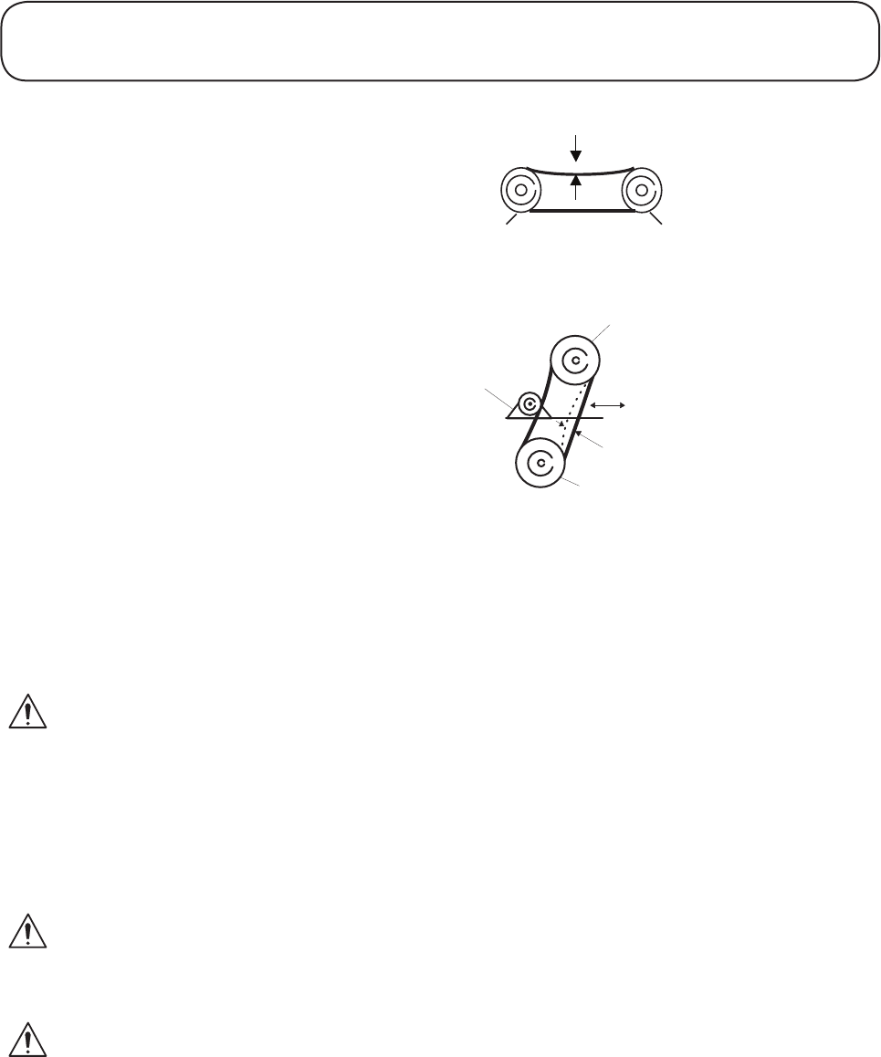
9. Adjust the two tensioning bolts (item 2, Fig 1)
equally to tension the twin drive belts. The
bolts are correctly tensioned when a deflection
of 13 mm is achieved using finger pressure.
Refer to Fig 3.
10. Tighten the locknuts (item 1) and nuts (item
5). Refer to Fig 1.
11. Re-check the belt tensions as previously
described and readjust if necessary. The twin
drive belts are matched but it is quite normal
for there to be slight differences in tension
between them.
ASSEMBLING THE MOWER
Fig 1
Cutterhead
A A
Fig 2
1. Nut
2. Tensioning Bolt
3. Mounting Bolt
4. Washer
5. Nyloc Nut
.....................
........
"
"
13mm
""""""1" " " """"""""""2
Fig 3
1. Drive pulley attachment (cutterhead)
2. Countershaft pulley (Power unit)

1.21 1.21
Assembling the Cutterhead Attachment
to the Power Unit continued
12. Refit the drive belt from the engine to the
countershaft pulley.
13. Refit the transmission guard to the power unit
and drive cover to the cutterhead.
To remove the cutterhead attachment from the
power unit:
This is achieved by adopting the procedure. ‘To
assemble the cutterhead attachment to the
power unit’ in reverse order.
14. Route the cutterbrake cable from the rotary
attachment over the countershaft pulley shaft
on the power unit, under the support bracket
and secure with a cable tie.
15. Route the cutterbrake cable over the micro
switch bracket (fitted to the side of the
engine) and secure at the same position as the
microswitch wires with a cable tie.
16. From the microswitch bracket route the
cable to follow the cutter clutch cable up
the left hand handlebar to the anchor bracket
and secure the cable adjuster into the bracket
using the two nuts provided, refer to
MAINTENANCE - RUNNING IN
PERIOD - AT FIRST 50 HOURS OF USE
- CHECK CUTTERHEAD BRAKE
CABLE ADJUSTMENT.
17. Remove the pushfix which is secured to the
eye at the end of the cutterbrake cable inner.
18. Fit the cable eye over the pin on the cutter
clutch lever and secure into position with the
pushfix.
19. Adjust the cutterbrake cable, refer to
MAINTENANCE - RUNNING IN
PERIOD - AT FIRST 50 HOURS OF USE
- CHECK CUTTERHEAD BRAKE
CABLE ADJUSTMENT.
20. Refit the transmission guard to the power unit
and the drive cover to the cutterhead.
WARNING: PREVENT ACCIDENTS - Never
operate the mower with the transmission guard
or drive covers removed.
ASSEMBLING THE MOWER

1.22 1.22
Safety Notice
WARNING: PREVENT ACCIDENTS - Before
operating the mower it is essential that;
- The operator reads and understands this
manual.
- The daily maintenance checks have been
properly carried out and the mower is in
good working order.
- The operator should wear safety clothing
and eye protection. Failure to do so could
result in risk to health and safety.
- The area where the equipment is to be used
is inspected and all objects which may be
thrown by the machine are removed.
Operator Presence Control
The controls incorporate an operator presence
control (OPC) which is provided for the protection
of the safety and health of the operator. This system
has been designed to ensure that the cutterhead
drive and ground drive clutches are automatically
disengaged in the event of the operator releasing
hold of the handlebars for whatever reason. Each
handlebar is provided with an OPC lever and these
are mechanically linked such that operation or
either will activate the system. These levers are
lightly spring loaded and are held down by the palm
of the hand during operation. Release of the OPC
levers will cause the cutterhead clutch to disengage
(activating the brake to arrest the rotation attach-
ment cutting devices).
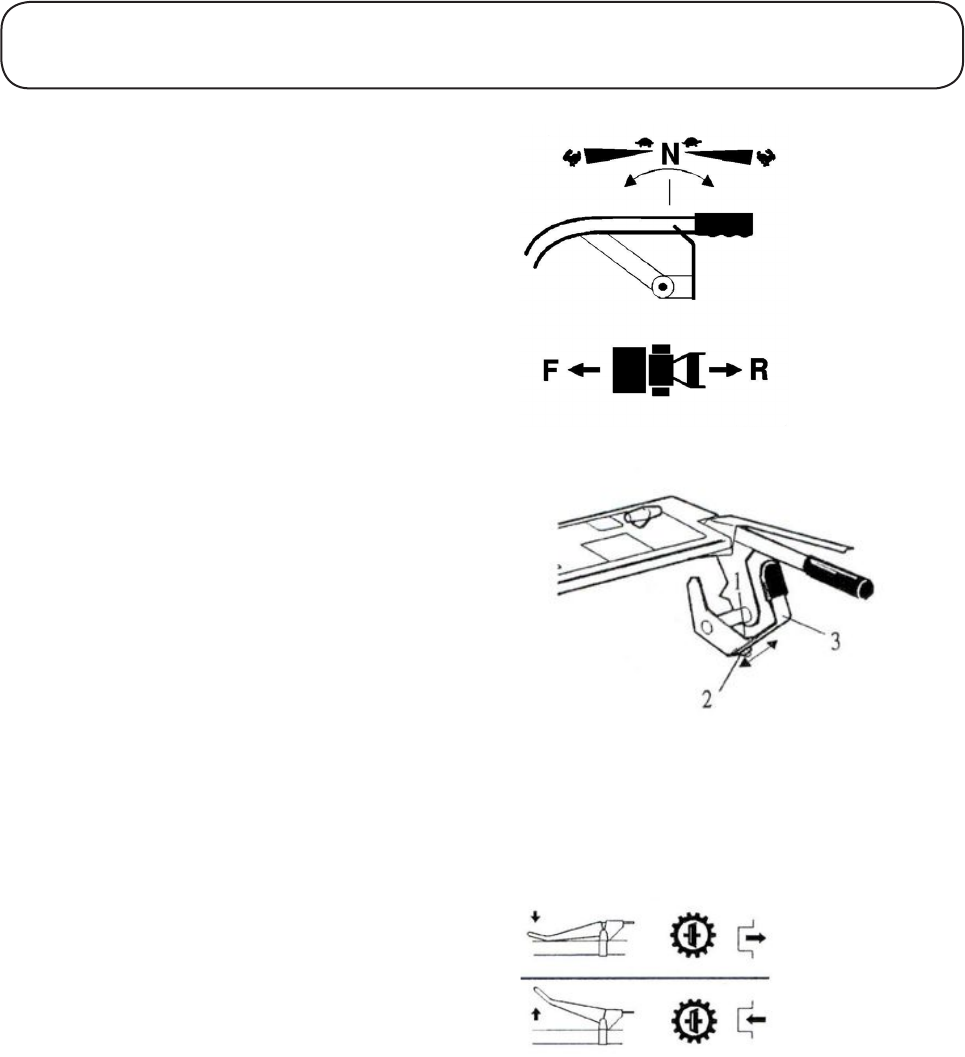
The travel speed rocker levers are spring loaded and
will return to the neutral position when released
thereby halting the motion of the machine.
The engine can only be started when the cutterhead
and ground speed controls are deactivated. The
integral switch sensors will not allow the engine to
be started unless this condition is satisfied.
WARNING: PREVENT ACCIDENTS - Do
not operate the mower if the operator presence
controls are defective in any way. ALWAYS
replace faulty parts and check that they function
correctly before operating the mower.
OPERATING THE MOWER
1.23 1.23
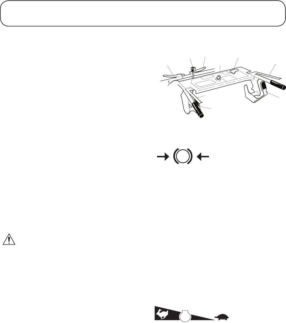
Identification of Controls
1. Transmission Bypass Valve Lever
2. Cutterhead Clutch Control Lever
3. Parking Brake Lever
4. Throttle Control
5. Operator Presence Control (OPC) Levers.
6. Travel Rocker
7. Ignition Switch
Braking System
Parking Brake: The hydrostatic axle unit incorpo-
rates an integral parking brake. This is operated by
the forward right hand lever. To operate the parking
brake, depress the lever until the spring loaded
locking catch automatically engages. To release the
parking brake, depress the lever until the locking
catch becomes free and then move it out of engage-
ment, release the brake lever.
Service Brakes: Service braking is achieved by
the hydrostatic transmission system. When the
forward and reverse travel controls are released or
the engine speed is reduced, service braking occurs
to reduce the travel speed.
WARNING: PREVENT ACCIDENTS - The
service braking system will not hold the mower
at a standstill. ALWAYS ensure that the park-
ing brake is engaged to park the mower at a
standstill.
Throttle Control
Operate the throttle control forwards to in-
crease the engine speed.
Operate the throttle control backwards to re-
duce engine speed.
Note: The engine speed dictates the speed of the
other functions, i.e. travel and cutterhead.
Travel
The forward and reverse travel rocker levers are
duplicated on each handlebar. These are mechani-
cally linked and activation of either will achieve
the desired function. The control levers are spring
centred and will automatically take up the ‘neutral’
position when deactivated.
OPERATING THE MOWER
P
Parking brake engaged
Engine speed
Fast Slow
1
2
34
5
5
6
6
7
1.24 1.24
Travel continued
Forward travel: Grip either handlebar and lay the
thumb over the travel rocker lever. Push forward
with the thumb to travel in the forward direction.
The forward speed will increase as the rocker
lever is pushed further forward or decrease as the
lever is allowed to return under the action of the
return spring. The required forward speed will be
maintained by maintaining the control lever in the
desired position.
Reverse travel: Grip either handlebar and lay the
thumb over the travel rocker lever. Pull backwards/
downwards with the base of the thumb to travel in
a reverse direction. The reverse speed will increase
as the rocker lever is further depressed or decrease
as the thumb pressure is reduced and the lever
returns under the return spring action.
Stop travel: Release the travel rocker lever and it
will automatically return to the neutral position,
thereby causing the mower to come to a standstill.
Adjustment of travel rocker levers: Both LH and
RH travel rockers levers are adjustable for operator
comfort. To adjust, slacken the appropriate bolt (1)
and move the lever assembly (3) in the required
direction. Retighten the clamp bolt securely before
operating machine.
Transmission Bypass Valve Control
When the engine is switched off, the hydrostatic
transmission is locked and acts as an effective
brake. This prevents the mower from being moved.
Activation of the bypass valve lever will unlock the
transmission and allow the machine to be moved
in a forward or reverse direction. Depress and hold
the bypass valve lever before attempting to move
the mower and release it on completion of the
manoeuvre.
IMPORTANT: PREVENT DAMAGE - Do not
operate the bypass valve lever while the engine
is running as this will cause a rapid temperature
rise in the hydrostatic system.
OPERATING THE MOWER
1.25 1.25
Ignition Switch
The engine may only be started when the ignition
switch is in the ‘on’ position (B).
WARNING: PREVENT ACCIDENTS - Always
switch the ignition key to the ‘off’ position (A)
and remove the key when the mower is not in
use.
Cutterhead Drive Operation
The cutterhead drive engagement mechanism is
protected by the Operator Presence Control (OPC)
system.
To engage cutterhead drive: Push the cutterhead
clutch control lever forwards with the left hand
while pushing downwards on the OPC lever with
the palm of the right hand, release the cutterhead
clutch control lever and the cutterhead drive will
remain engaged until such time as the OPC levers
are released. The OPC levers are duplicated on
each handlebar and operation of either (or both)
will keep the system activated.
To disengage cutterhead drive: Release the OPC
levers. Observe that the cutterhead clutch control
lever automatically returns backwards to the disen-
gaged position.
WARNING: PREVENT ACCIDENTS - Do not
operate the mower if the handlebar controls of
the operator presence control system are defec-
tive in any way. ALWAYS replace faulty parts
and check that they function correctly before
operating the mower.
Starting the Engine
This machine is fitted with an Engine Start
Lockout, refer to OPERATOR PRESENCE
CONTROL.
WARNING: PREVENT ACCIDENTS - Before
starting the engine check that:
- The area is clear of bystanders.
- The cutterhead drive is disengaged.
- The parking brake is engaged.
- The travel controls are in neutral.
- You have read and understood the Safety
Precautions Section in this manual.
OPERATING THE MOWER
2
12
STOP
A
B
STOP
A
B
Engage Cutterhead Drive
Disengage Cutterhead Drive
1.26 1.26
OPERATING THE MOWER
Starting the Engine continued
CAUTION: PREVENT DAMAGE - Before
attempting to start the engine, ensure that the
crankcase oil level is correct and check the fuel
level.
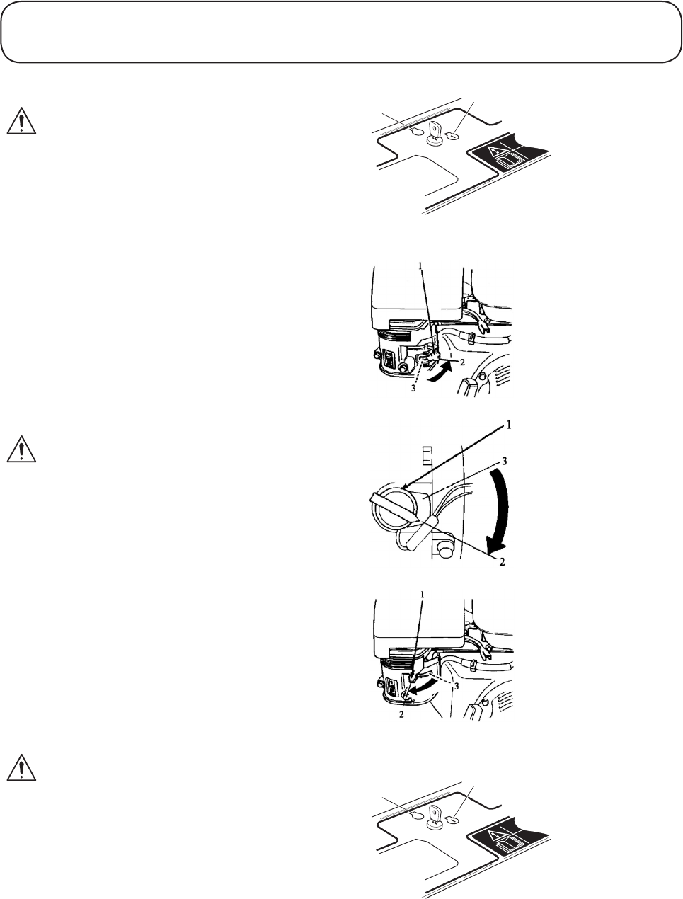
Starting a cold engine: Turn the fuel valve and
the engine switch to the ‘on’ position. Set the
throttle control lever to approximately 70% full
throttle and close the choke lever.
Turn the ignition key to the ‘on’ (B) position.
Pull the start grip with a steady motion to start the
engine.
Gradually return the choke lever to the open posi-
tion as the engine warms up.
Once the engine has warmed up increase the throt-
tle setting as required for operation.
CAUTION: PREVENT DAMAGE - Do not
allow the start grip to snap back against the
engine. Return it gently to prevent damage.
Starting a warm engine: Follow the procedure
for ‘Starting a cold engine’ except the use of the
choke will not normally be required when starting
a warm engine.
Stopping the Engine
To stop the engine: Turn the ignition key to the
‘off’ (A) position.
In normal use bring the mower travel to a stop,
disengage the cutterhead drive and engage the
parking brake before stopping the engine.
WARNING: PREVENT ACCIDENTS - If the
engine fails to stop when the ignition switch
is switched to the ‘off’ position (A), turn the
engine to the ‘off’ position and close the fuel
valve. The engine may also be stalled by closing
the choke and opening the throttle control or
removing the spark plug lead.
STOP
A
B
STOP
A
B
1. Fuel Valve
2. On
3. O
1. Engine Switch
2. On
3. O
1. Choke Lever
2. Close
3. Open

1.27 1.27
OPERATING THE MOWER
General Operating Hints
1. The rotational speed of the cutterhead should
always be kept as high as possible to maintain
the highest quality of cut. This in turn requires
the mower engine speed to be kept as high as
possible.
2. The quality of cut will deteriorate if the
forward speed is too high. Always balance the
quality of cut with the work rate required and
set the forward speed accordingly.
3. Never let the mower labour. Reduce the
forward speed or increase the height of cut.
If a verge attachment is used, ensure that the
cutting cylinder is not in heavy contact with
the bottom blade. Regularly check the cutting
cylinder to bottom blade adjustment every few
hours even though cutting performance seems
satisfactory. Rapid wear will take place if the
bottom blade is in heavy or zero contact with
the cutting cylinder.
4. Rotary attachment. Ensure that the
cutterblade and bottom plates are maintained
in good condition.
5. Always disengage the cutterhead drive
when transporting across ungrassed areas.
Verge attachment: Grass will lubricate the cutting
edges in work. Excess heat will build up if the
cutting cylinder is run out of work which will
cause rapid wear to place. For this reason it is also
wise to reduce the cutting cylinder speed when
mowing lightly grassed areas or when the grass is
dry.
6. Cutting performance is best when cutting
against the lie of the grass. In order to take
advantage of this fact the operator should
attempt to alternate the direction of
mowing between cuts.
Adjusting Height of Cutter
Verge attachment
Remove the set screw ‘A’ at each end and use a
suitable tommy bar to reposition the height adjust-
ments quadrants ‘B’ and align with the desired hole
locations. Ensure that the same hole locations are
selected at each end. Finally refit the setscrew and
tighten securely.
1.28 1.28
OPERATING THE MOWER
Adjusting Height of Cutter continued
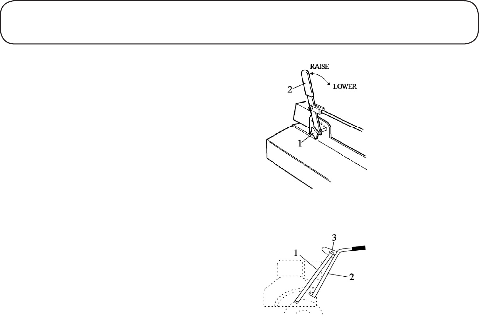
30’’ Rotary Attachment.
Loosen hand knob (1) sufficiently to allow lever
(2) to be moved to the required height of cut posi-
tion. Retighten the hand knob to secure the height
of cut lever in position.
Handlebar Height Adjustment
The height of the handlebar may be adjusted at the
connection between the handlebar stays (1) and
the plate on the handlebar (2). Adjustment holes
(3) provide 3 alternative handlebar settings. Ensure
that the handlebars are set at the same level on each
side of the mower.
Note: The length of the connecting rods to the
travel control rocker levers must be re adjusted as
necessary to ensure correct operation.
1. Hand knob
2. Height of Cut Lever
1. Handlebar Stay
2. Handlebar
3. Adjustment Holes

1.29 1.29
Maintenance
WARNING: PREVENT ACCIDENTS - When carrying out maintenance procedures it is
essential that:
- The engine is switched off, the spark plug lead removed and the ignition switch is in the ‘off’
position.
- The parking break is applied.
- You have read and understood the
maintenance section of the Operator’s Manual.
IMPORTANT: PREVENT DAMAGE - Regular maintenance is essential for the continued safe
operation of the mower. Correct servicing will prolong the working life of the mower and safeguard the
“Hayter Warranty”. Always fit genuine ‘Hayter service parts’ as these are accurately matched to the
required duty.
Dirt and contamination are the enemies of any hydraulic system. When carrying out maintenance pro-
cedures on the transmission system always ensure that the work area and components are thoroughly
clean before, during and after refitting.
The recommended service intervals are based on normal operating conditions. Severe or unusual con-
ditions will necessitate shorter service intervals.
WARNING: PREVENT ACCIDENTS - Remember the engine and transmission oil is hot after mower
use. Allow to cool before carrying out maintenance procedures.
WARNING: PREVENT ACCIDENTS - Use hazardous substances carefully. The following fluids are
identified as being hazardous;
Substances Assessed risk
Petrol High
Lubricating Oil Low
Transmission Oil Low
Gear box oil Low
Grease Low
When using any of the above fluids it is recommended that the eye protection and gloves are worn and care
is taken to prevent spillage.
Avoid contact with skin; wash off spillage with soap and water.
In case of petrol, keep away from all sources of ignition and wash with soap and water. Remove any con-
taminated clothing and wash thoroughly before use.
Avoid contact with eyes; wash with running water and
seek medical attention.
Avoid ingestion; If swallowed seek medical attention.
CAUTION: PREVENT ENVIRONMENTAL DAMAGE - Dispose of hazardous substances correctly.
MAINTENANCE

1.30 1.30
MAINTENANCE
Engine
Refer to the engine manual for engine maintenance
information. The engine is governed to run at a
maximum speed of 2900 r.p.m. Under no circum-
stances must this speed be modified.
Running In Period - At First 50 Hours of
Use
Check wheel nut torque: Power unit wheel nut
torque setting 80Nm (60lbs ft).
Check belt tension - Engine / Countershaft
drive: Ensure that the cutterhead drive is disen-
gaged and check the free play at the centre of the
belt as shown using finger pressure. If adjustment
is required, slacken the engine securing bolts and
move the engine towards the rear of the mower
until the correct tension is obtained. Finally tighten
the engine securing bolts.
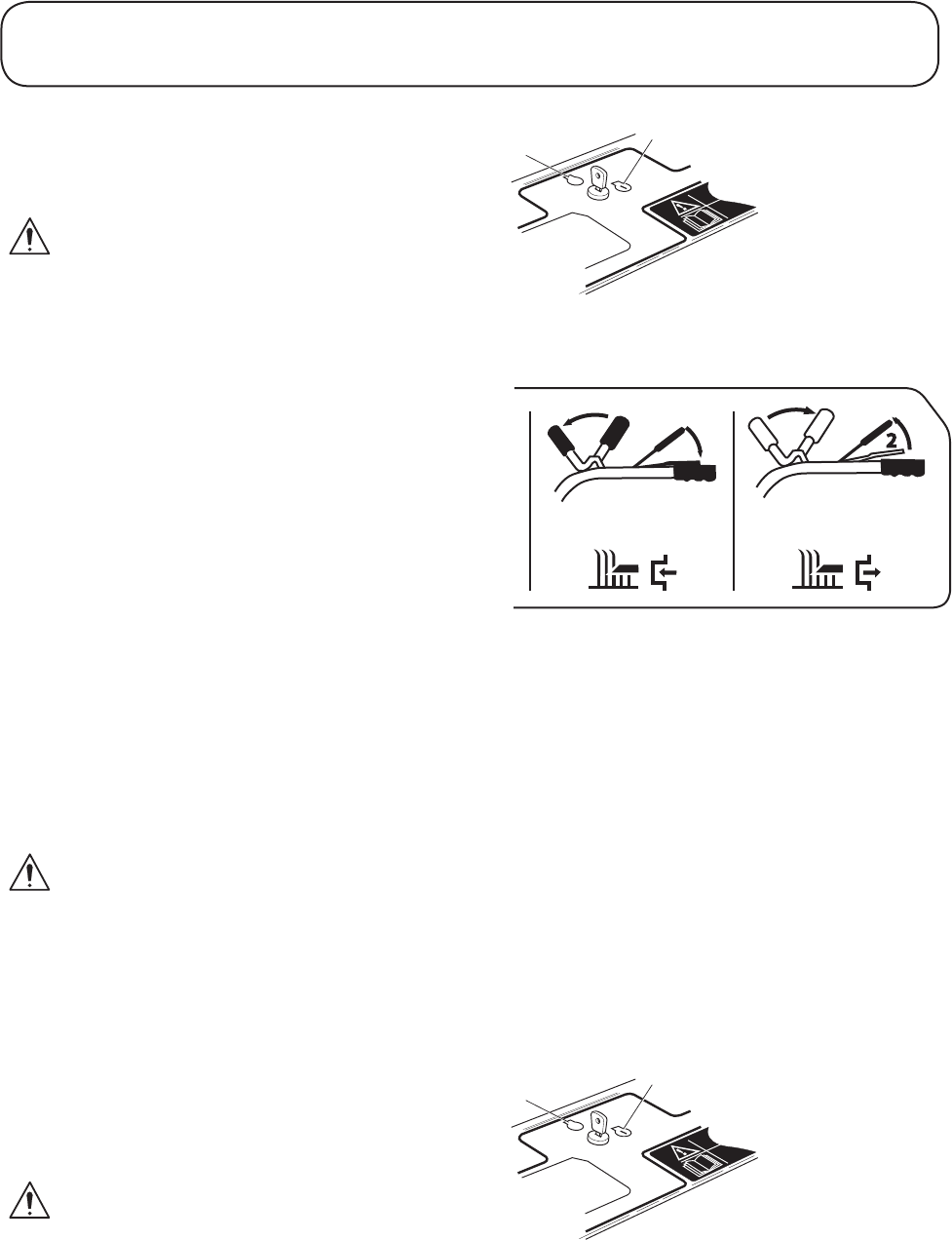
Check cutterhead drive clutch cable adjust-
ment: Ensure that the cutterhead drive is disen-
gaged. Adjust the clutch cable by slackening off
the locknuts at the anchor plate on the left hand
handlebar and moving the adjuster to obtain 3mm
free movement of the cable. Retighten the locknut.
Note: The cutterhead drive clutch cable adjuster
is positioned to the left of the cutterhead brake
adjuster when fitted with a rotary cutterhead attach-
ment.
Check belt guide clearance: Engage the cutter-
head drive and check the clearance between the
belt guides and the belt as shown. If adjustment
is required slacken the idler pulley mounting bolt
and move the belt guides into the correct position.
Retighten the bolt.
Check cutterhead brake cable adjustment (Ro-
tary attachment only): Ensure that the cutterhead
drive is disengaged. Adjust the cutterhead brake
cable by slackening off the locknuts at the anchor
plate on the left hand handlebar and moving the
adjuster to obtain 6mm free movement of the cable.
Retighten the locknut.
Note: The cutterhead brake cable adjuster is po-
sitioned to the right of the cutterhead drive clutch
cable adjuster.
1. Countershaft Pulley
2. Engine Pulley
1. Anchor Plate on Handlebars
2. Locknut
3. Adjuster
1. 6mm Gap
2. Belt Guides
3. Engine Pulley
4. Idler Pulley
5. Countershaft pulley
1. Anchor Plate on Handlebars
2. Locknut
3. Adjuster
1.31 1.31
MAINTENANCE
Running In Period - At First 50 Hours of
Use continued
Check belt tension - Cutterhead input drive:
Check the free play at the centre of the drive belt
span as shown using finger pressure. If adjustment
is required, refer to MOUNTING OF CUTTER-
HEAD ATTACHMENT.
Check belt tension - Main engine drive: Check
the free play at the centre of the drive belt as shown
using finger pressure. If adjustment is required
adjust the jockey pulley bracket until the correct
belt tension is obtained.
Daily and Before Use
Check engine oil: If the oil level is below the
upper mark on the dipstick, top up with the correct
grade of engine oil, refer to ENGINE OWNER’S
MANUAL.
Air cleaner (Dual element type): Check the air
cleaner elements for holes or tears and replace if
damaged. Clean the paper element.
CAUTION: PREVENT DAMAGE - Always
replace a damaged air cleaner or damage to the
engine will result. NEVER run the engine with-
out the air cleaner correctly fitted.
Check fuel level: Top up as necessary with
unleaded petrol. Always top up before storing the
mower over night to prevent water condensation
from contaminating the fuel.
WARNING: PREVENT ACCIDENTS - Never
use petrol or low flash point solvents when
cleaning the air cleaner elements. A fire or
explosion could result.
WARNING: PREVENT ACCIDENTS - Petrol
is highly flammable. Observe all relevant safety
precautions. Refer to SAFETY PRECAUTIONS
- PREPARATION.
.....................
........
"
"
13mm
""""""1" " " """"""""""2
1. Drive Pulley Attachment (Cutterhead)
2. Countershaft Pulley (Power unit)
1
2
3
1. Drive Pulley Attachment (Cutterhead)
2. Countershaft Pulley (Power unit)

1.32 1.32
MAINTENANCE
Daily and Before Use continued
Check hydrostatic unit oil level: Always check,
prior to starting, when the mower is cold. Remove
the reservoir cap and check the fluid level. The
level should not be above the ‘cold’ mark. Top up,
if necessary to the cold mark with the
recommended grade of transmission fluid, refer
to SPECIFICATIONS, and replace the reservoir
cap. If the natural colour of the transmission fluid
has become ‘milky’ or black, it is possible that an
overheating or water contamination problem exists.
In such cases, the mower should be checked by a
Hayter dealer and the oil should be changed, refer
to MAINTENANCE - EVERY 200 HOURS.
IMPORTANT: PREVENT DAMAGE - Do not
overfill as this will reduce the expansion vol-
ume in the reservoir and leakage may occur
at operating temperature. If frequent topping
up is required, locate and repair any leaks.
Operation at a low fluid level may result in
permanent internal damage.
Check the operator presence controls: Stop the
engine.
Check the operation of the microswitches, ensure
the operation arm is free of any debris and that
the roller rotates freely. Spray the hydrostatic unit
neutral detent microswitch with a water repellent
lubricant.
Engage the cutterhead drive and operate the OPC
levers. The engine should not start when the
normal starting procedures are followed.
Start the engine, engage the cutterhead drive and
operate the OPC levers. Release the OPC levers
and ensure that the cutterblades cease to rotate
within 5 seconds.
Operate and hold the travel rocker lever in the
forward travel direction. The engine should not
start when normal starting procedures are fol-
lowed. Carry out a similar check for reverse travel.
WARNING: PREVENT ACCIDENTS - Keep
bystanders away when checking the opera-
tor presence control system. DO NOT use the
mower unless the operator presence controls
work correctly as described below. Consult your
Hayter dealer if the system malfunctions.

1.33 1.33
Daily And Before Use continued
Check travel controls: Start the engine.
Engage forward travel and operate at maximum
speed over level ground, release the travel controls
and ensure that the mower comes to a stop.
Engage reverse travel and operate at maximum
speed over level ground, release the travel controls
and ensure that the mower comes to a stop.
Check fasteners: Check that all nuts, bolts, pins
and linkages are secured correctly in place and are
in good order.
Check tyres: Examine the condition of the tyres
and check that the inflation pressures are correctly
set, refer to SPECIFICATIONS.
Verge attachment: Examine the condition
of the cutting cylinder and the bottom blade,
adjust as necessary, refer to MAINTENANCE
- CUTTERHEAD CYLINDER TO BOTTOM
BLADE ADJUSTMENT.
Rotary attachment: Check the condition of the
cutterblades and mounting arrangement for signs
of wear, damage or looseness. Ensure that the
cutterblades are not bent or cracked and that the
cutterblade securing bolts are tight. Damaged or
excessively worn cutterblades may be out of
balance which will cause excessive vibration this
may lead to breakage or result in serious damage
to the machine.
WARNING: PREVENT ACCIDENTS - Never
use the mower if the cutterblades and mounting
arrangement are seriously worn, damaged, out
of balance or loose.
Remove all grass cuttings and build up of debris
from the cutterhead area, the cooling air intake
areas/external surfaces of the engine and the inter-
lock microswitches.
WARNING: PREVENT ACCIDENTS - Check
all guards and safety devices. Never operate the
mower unless the guards are securely in posi-
tion, in good condition and all safety devices are
in place and in good working order.
MAINTENANCE
1.34 1.34
MAINTENANCE
Every 50 Hours
Perform routine checks: Refer to DAILY
BEFORE USE.
Check power unit wheel nut torque: Wheel nut
torque setting - 80 Nm (60lbs ft)
Rotary attachment: Inspect the chain couplings
between the cutter headgear boxes. Inspect sprock-
et teeth and chains for signs or wear.
IMPORTANT: PREVENT DAMAGE - If the
chains / countershaft are removed for any reason,
ensure that the cutterhead phasing is correct after
refitting.
Lubrication
Transaxle: Check oil level on dipstick. This
should be level with the hole indicator on the dip-
stick. Top up if necessary with the correct grade of
transmission fluid, refer to SPECIFICATIONS.
Top up fluid should be introduced through the dip-
stick tube.
Cutterhead Gearbox (Rotary Attachment):
Remove filler plug on top of the gearbox and
check oil level. Gearbox should be 3/4 full. If nec-
essary top up with the correct grade of oil, refer to
SPECIFICATIONS.
General: Lightly apply a good quality general
purpose lubricating oil to the following points;
All linkage pivot points
All inner cables
Rear roller quadrant pivot bushes (Verge
Attachment).
Apply a good quality medium grade grease to the
following points:
Front wheels (Rotary Attachments).
Carrier pivot (Verge Attachments).
Cylinder bearing housings (Verge Attachments).
Chain couplings - between cutterhead gearboxes
(Rotary Attachment).

1.35 1.35
MAINTENANCE
Every 200 Hours
Perform routine checks: Refer to DAILY
BEFORE USE, EVERY 50 HOURS USE.
Change transmission fluid: Hydrostatic Unit.
IMPORTANT: PREVENT DAMAGE - Dirt and
contamination are the enemies of any hydraulic
system. Ensure that the work area and the com-
ponents are thoroughly clean before during and
after refitting. Do not allow debris to become
entrained within the hydraulic system.
It is recommended that the following procedure is
adopted when carrying out an oil change.
- Remove the lower left hand cover and the rear
fan guard screen to gain access to the hydro
static unit.
- Disconnect the ball joint from the lower
actuating lever by removing the 5/16” UNF hex,
nut and spring washer.
- Slacken the main engine drive belt by loosening
the jockey pulley bracket.
- Remove the ¼” UNC Setscrew and retaining
washer and remove the fan.
- Remove the 4 mounting bolts and support the
hydrostatic unit.
- Remove the connecting pipe from the top of the
hydrostatic unit and allow the residual oil to
drain into a suitable can.
- Lift the unit and unhitch the drive belt.
- Lower the hydrostatic unit and remove from the
machine.
- Thoroughly clean dirt and debris from around
the hydrostatic unit.
- Remove the drain plug and allow the oil to
drain into a suitable can. Rotate the input shaft
to assist the draining procedure. Finally replace
the drain plug and tighten securely.
- Turn the unit the right way up and remove the
plastic cup (Note this has a left hand thread) and
the upper bleed plug.

1.36 1.36
MAINTENANCE
Every 200 Hours continued
- Carefully refill the unit with fresh
transmission oil of the recommended grade,
refer to SPECIFICATIONS, until fluid is seen
to flow from the bleed plug aperture. Replace
the cap securely and hand tighten the bleed
plug.
- Remove the plastic reservoir (note this has a left
had thread), from the power unit. Thoroughly
clean and ensure that the mesh screen is fully
open.
- Refit the hydrostatic unit following the
dismantling procedure in reverse order. Torque
the 4 mounting bolts and the fan mounting bolt
to 10.2 - 11.3Nm (7.5 - 8.3 lbs ft).
- Retention the engine drive belt, refer to
RUNNING IN PERIOD.
- Reconnect the connecting pipe.
- Reconnect the ball joint to the actuating lever.
- Replace lower cover and fan guard screen.
- Do not replace the plastic reservoir at this stage.
- Remove the bleed plug from the top of the
hydrostatic unit. Top up through the reservoir
base until oil flows from the bleed plug
aperture and keep topped up during the
following procedure.
WARNING: PREVENT ACCIDENTS - Do not
proceed to the next stage unless all guards have
been replaced and fully secured.
- Start the engine and maintain as low a throttle
setting as possible.
- Ease the machine forwards and backwards
until all residual air has bled from the bleed
plug aperture. Ensure that the reservoir cup is
kept topped up during this process.
- Stop the engine and set the parking brake.
- Replace the bleed plug and secure.
- Replace the reservoir cap and hand tighten.

1.37 1.37
MAINTENANCE
Every 200 Hours continued
- Top up the reservoir to the ‘’COLD’ level and
replace the cap. Clean off any surplus oil from
around the reservoir and the hydrostatic unit to
prevent a build up of debris.
The procedure has now been completed.
Note - The oil change procedure can be accom-
plished without removing the hydrostatic unit but
it will take an exceptionally long period to refill
the unit through the small diameter feed pipe.
Check all belt tensions: Refer to RUNNING IN
PERIOD.
Check cutterhead drive clutch cable adjust-
ment: Refer to RUNNING IN PERIOD.
Check condition of cutterhead drive brake pad:
Replace if excessively worn.
Check cutterhead drive brake adjustment:
Refer to RUNNING IN PERIOD.
Power Unit General Maintenance
Transmission bypass valve: The lever should be
adjusted so that the bypass valve plunger on the
hydrostatic unit is fully depressed when the lever
is just touching the handlebar cross-tube.
To adjust setting slacken adjuster nuts at end of
cable. Adjust cable setting and lock the adjuster
nuts. Check that the machine can be moved with
the engine switched off when the bypass valve
lever is operated.
Parking brake - cable adjustment: To adjust the
cable, slacken off the locknut and turn the cable
adjuster. A correctly set cable should have no
slack. When the brakes are applied, the brake lever
should operate smoothly and lock at the end of its
travel.
Check that the parking brake has been applied by
depressing the transmission bypass valve lever and
try to pull or push the machine. The wheels should
be locked. Re adjust the cable if the machine is
able to be moved. Tighten the cable adjuster lock-
nuts.
1.38 1.38
MAINTENANCE
Power Unit General Maintenance
continued
Travel Speed: The forward and reverse stops re-
strain the hydrostatic unit actuating lever from be-
ing moved excessively and prevent internal compo-
nents from being damaged. The setting dimensions
shown should be used. These dimensions may be
increased if the maximum speed of the machine is
to be reduced, but the dimensions should never be
less than those indicated.
To set the forward / reverse stops correctly for min-
imum travel speeds, loosen the adjuster locknuts
and screw the adjuster screws away from the actu-
ating lever. Operate the actuating lever by hand to
its extreme / full travel position for forward travel
and move the adjuster screw to stop the actuating
lever 1.6mm before the extreme / full travel posi-
tion is reached. Repeat this procedure for reverse
travel except move the adjuster screw to stop the
actuating lever 5mm before the extreme / full travel
position is reached. Tighten the locknuts.
IMPORTANT: PREVENT DAMAGE - The
hydrostatic unit may sustain permanent damage
if the forward and reverse stops allow greater
travel than the limits indicated.
Neutral detent mechanism: Should the mower
creep forwards or backwards when the travel speed
control levers are in the neutral position it will be
necessary to adjust the neutral detent setting.
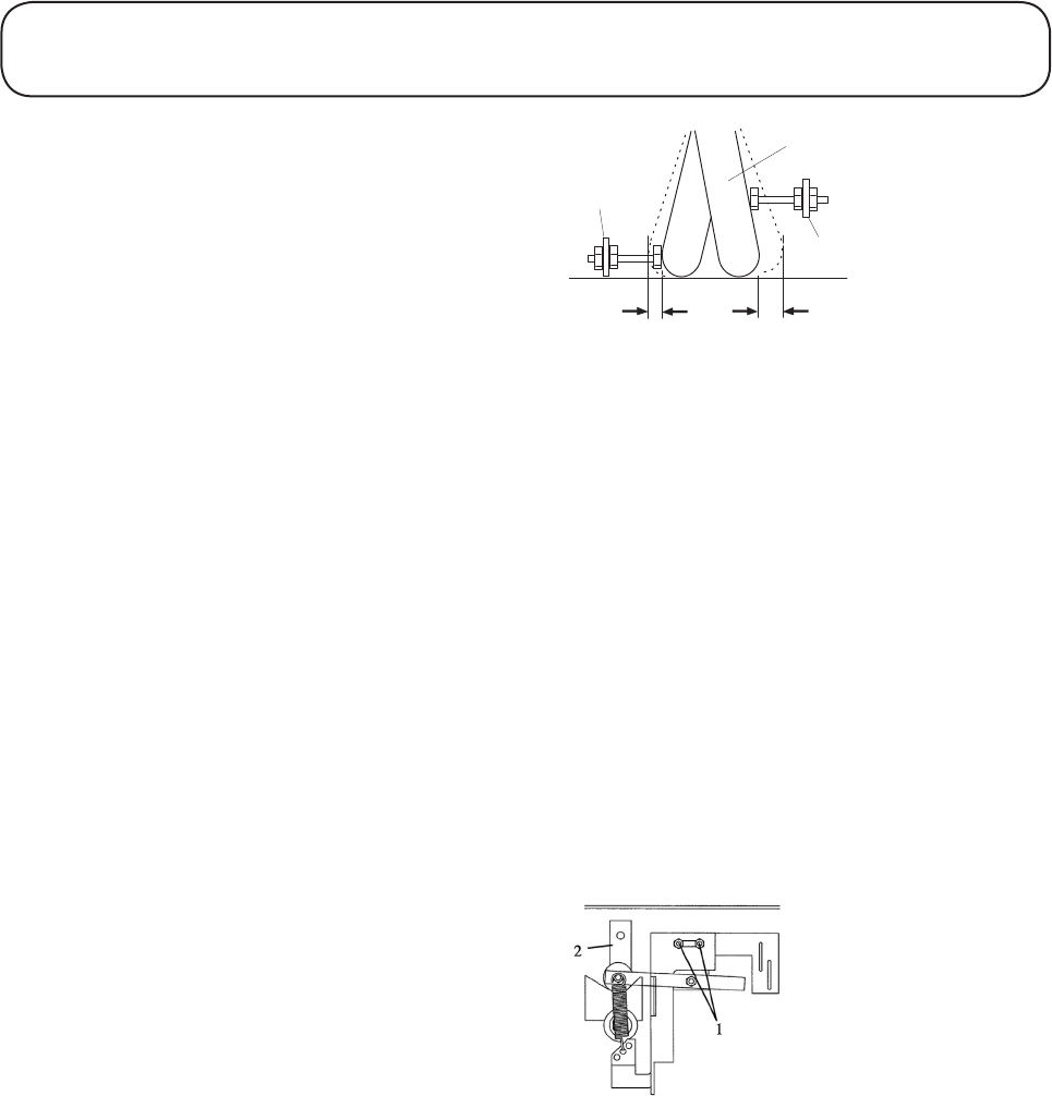
Slacken hex. nuts (1) and adjust the bracket on the
slots until the actuating lever (2) of the hydrostatic
unit is parallel with the side of the engine deck
(Neutral position).
Retighten the hex nuts securely.
Recheck the mower operation and make further
adjustments is necessary.
1
2
3
5mm
min.
1.6mm
min.
1. Forward stop / Adjuster
2. Reverse stop / Adjuster
3. Hydrostatic unit actuating lever
1. Hex nuts
2. Actuating lever (view from under the machine)
1.39 1.39
MAINTENANCE
Power Unit General Maintenance
continued
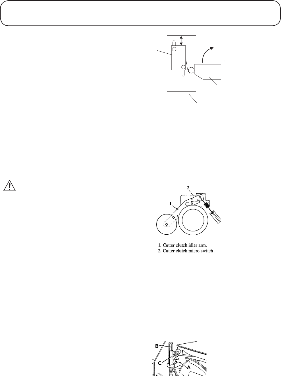
Adjustment of engine lockout switches: The
micro switch must be positioned such that when
the actuating levers (transmission neutral detent
lever or cutter clutch idler arm) are in the neutral/
disengaged position the switches must be fully
closed. To adjust, set the appropriate lever in the
neutral/disengaged position, slacken off the switch
mounting bolts and slide the switch along its
mounting slots until the switch is heard to click
shut. Retighten mounting bolts.
Check the operation of the operator presence con-
trols, refer to DAILY BEFORE USE.
Verge Attachment
IMPORTANT: PREVENT DAMAGE - It is
essential that the relationship between the
bottom blade and the cutting cylinder is kept in
good adjustment in order to ensure good
cutting performance, minimum power con-
sumption and prolonged life for the cutting
edges.
Cutterhead cylinder to bottom blade adjust-
ment: Carry out the following procedure before
commencing work and re-check the settings every
few hours.
Check that the cutting cylinder is correctly set to
the bottom blade by holding a thin piece of paper
between the cutting cylinder and the bottom blade
as shown. Carefully rotate the cylinder and check
that the paper is cut cleanly at all points along the
length of the blade. Hold the paper at 90 degrees
(right angles) to the bottom blade to obtain the cor-
rect cutting action.
If adjustment is necessary proceed as follows:
Slacken the nearside and offside setscrews ‘A’.
Slacken both locknuts ‘B; and turn the adjusting
nuts ‘C’ in a clockwise direction. The adjust-
ing nuts should be rotated one flat of the nut at
a time, alternating end to end, while rotating the
cutting cylinder backwards until it is felt to be in
‘fleeting’ contact with the bottom blade along its
entire length. Re check the cutting action along the
length of the bottom blade using a thin piece of
paper and making marginal adjustments as neces-
sary.
1
2
3
1. Transmission micro switch
2. Transmission neutral detent lever
3. Chassis
1. Cutter clutch idler arm
2. Cutter clutch micro switch

1.40 1.40
MAINTENANCE
Verge Attachment continued
Finally tighten locknuts ‘B’ using 2 spanners to
avoid inadvertent movement of adjuster nuts ‘C’
and tighten setscrews ‘A’. Recheck the cutting
action as previously described to ensure that the
setting has not moved.
If it is impossible to obtain a good clean paper
cut across the entire length of the bottom blade it
will be necessary to remove any high spots on the
spirals/bottom blade with a stone. In severe cases
it will be necessary to regrind the cutting cylinder
and the bottom blade, refer to GRINDING.
Do not be tempted to over adjust causing heavy
contact between the cylinder and bottom blade
as this will cause very rapid uneven wear to take
place leading to tram lining and waviness of the
cutting edges. The frictional losses will be high
and a significant amount of power will be absorbed
thus reducing the power available for cutting. The
heating effect due to friction will cause excessive
expansion to take place which will further aggra-
vate the situation by increasing the contact pres-
sure.
If the cutterhead is allowed to operate for more
than a few hours without adjustment the running
wear will eventually cause the cylinder to run out
of contact with the bottom blade. At this stage very
rapid rounding of the cutting edges will occur as
grass and abrasive particles pass through the clear-
ance between the blades.
Lack of attention to adjustment can therefore
be foolhardy as maintenance costs will escalate.
Quality of cut will also be seriously affected as
will the health and growth of the grass.
An experienced operator will notice when a cutter-
head starts to go out of adjustment, when the grass
ceases to be cut cleanly and the cut ends become
ragged.
Cutterhead grinding: It will be necessary to
carry out a grinding operation to correct cylinder
spiral edges or a bottom blade edge which have
become excessively rounded or distorted. A bot-
tom blade which is nearing the end of its wear life
should be replaced and this should be ground on
its holder prior to fitting, refer to CUTTERHEAD
BOTTOM BLADE REPLACEMENT.

1.41 1.41
MAINTENANCE
Verge Attachment continued
Cutterhead grinding continued: When grinding
operations are necessary it is essential that both
cylinder and bottom blade are ground at the same
time. The only exception to this rule is when a new
cylinder is fitted in which case it is only neces-
sary to grind the bottom blade. All such grinding
operations should be carried out by your dealer on
a quality, well maintained cylinder / bottom blade
grinding machine.
Cutterhead bottom blade replacement: Remove
the bottom blade holder by removing the three
fixing bolts at each end and withdrawing from the
cutterhead. Remove the worn bottom blade and
discard the countersunk retaining screws. Fit the
new blade to the holder and loosely assemble with
new retaining screws. Tighten the centre retaining
screws to a torque of 54 Nm (40 lbs ft). Continue
by tightening the remaining fasteners to the same
torque by working from the centre out towards the
blade ends.
The new bottom blade must be ground on its hold-
er prior to refitting to the cutterhead.
Adjust the cutting cylinder position to give ade-
quate clearance for fitting the new bottom blade
holder. Refit the bottom blade holder assembly
using new fixing bolts and tighten securely. Finally
adjust the cylinder to the bottom blade, refer to
CUTTERHEAD CYLINDER TO BOTTOM
BLADE ADJUSTMENT.
Rotary Attachment
WARNING: PREVENT ACCIDENTS - NEVER
work on the cutterblades unless the spark plug
lead has been removed. The cutterblades have
sharp edges. ALWAYS wear strong gloves to
protect your hands when working on the cutter-
blades. DO NOT operate tools towards the cut-
ting edges to avoid the risk of injury should the
tool slip. ALWAYS use genuine Hayter replace-
ment parts.
WARNING: PREVENT ACCIDENTS -
ALWAYS renew both cutterblades on each bot-
tom plate to ensure the cutting mechanism is
balanced, NEVER replace cutterblades individ-
ually. ALWAYS use new bolts, nuts and washers
when fitting new cutterblades.
1.42 1.42
MAINTENANCE
Rotary Attachment continued
PREVENT DAMAGE: A damaged cutterblade
will cause the cutting mechanism to be out
of balance and excessive vibration will occur
which may lead to breakage. DO NOT use an
unbalanced cutting mechanism.
Replace the cutterblades every 2 years or sooner
if excessively worn or damaged.
WARNING: PREVENT ACCIDENTS - It is
wise to seek assistance when removing and
inverting the cutterhead attachment.
The condition of the cutterblades and the
mounting arrangement should be checked regu-
larly for signs of wear or damage. Ensure that
the cutterblades are not bent or cracked.
Regularly check that the bolts securing the cut-
terblades and bottom plate are secure.
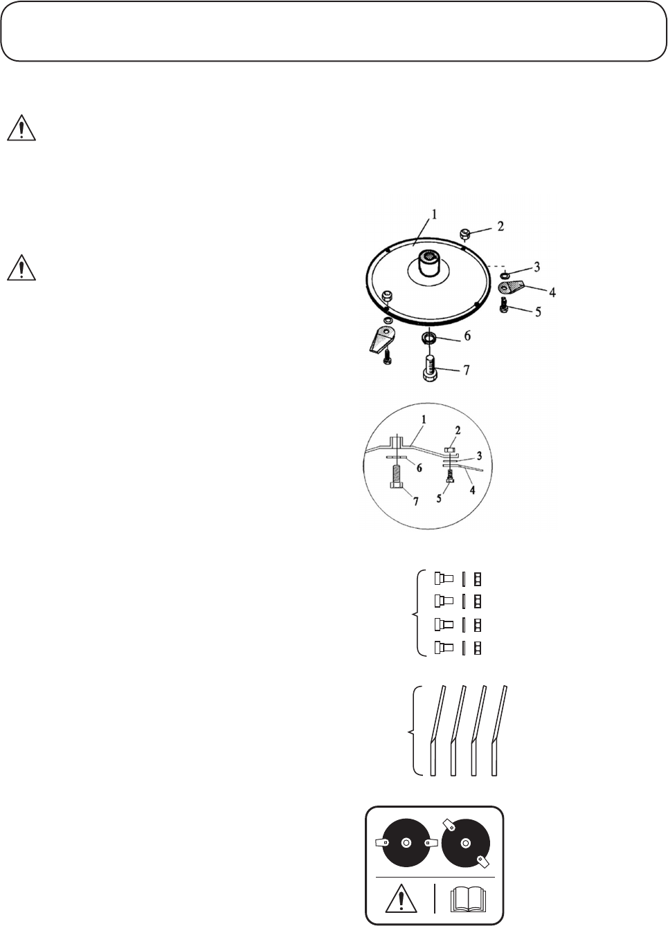
To remove the cutterblades: Remove the cutter-
blade nut (2) and bolt (5).
How to assemble the cutterblades: Assemble cut-
terblades (4) such that they are below and pointing
away from the bottom plate (1). Tighten the cut-
terblade nuts (2) and bolts (5) to a torque of 19Nm
(14 lbs. ft.).
Tighten the bottom plate bolt (7) to a torque of
54Nm (40lbs. ft).
Always replace the tab washer (6) before re-assem-
bly,
Cutterblades
Cutterblade phasing: IMPORTANT: PREVENT
DAMAGE - The cutterheads must be correctly
phased. Ensure that the cutterblades are fitted
into the correct mounting holes the underdeck
as shown.
Part No
HY590
Part No
2779
111"3904"A

1.43 1.43
PREPARING THE MOWER FOR STORAGE
Preparing the Mower for storage
Storage for long periods: To ensure that the mower is
maintained in good working order it is important that
the following procedure is adopted when the mower is
stored for periods in excess of one month. Refer to the
maintenance section and engine handbook as neces-
sary.
WARNING: PREVENT ACCIDENTS - Ensure
that the mower is outdoors, away from all possible
sources of ignition and that the engine is cool prior
to carrying out the following procedure.
Drain fuel from the engine and carburettor.
Disconnect the spark plug lead. Change the engine oil.
Remove the engine spark plug and pour a tablespoon
of clean engine oil into the spark plug aperture. Do not
exceed the stated volume of oil as engine damage may
occur on restarting. Operate the engine start grip sev-
eral times to crank the engine. This will distribute the
oil. Replace the spark plug.
Pull the engine start - grip slowly until resistance is
felt. Continue pulling until the notch on the starter pul-
ley aligns with the hole on the recoil starter as shown
in the engine Owner’s Manual. At this point, the intake
and the exhaust valves are closed and this will help to
protect the engine from internal corrosion.
Clean all areas of the power unit, engine and cutter-
head attachment.
Lubricate the mower.
Treat bare metal parts with a water repellent anti-
corrosion product.
Rest the machine on wooden blocks to remove the
weight of the mower from its wheels.
Cover the mower with a protective sheet and store it in
a dry, ventilated area.

1.44 1.44
GRASS CUTTING FAULTS
FAULT POSSIBLE CAUSE REMEDY
Uneven cut Undulating ground contours Change direction of cut
Cutterblades worn or damaged Sharpen or replace as necessary
Cutterblades out of balance Replace as necessary
Wheel damaged Inspect and replace as necessary
Scalping Height of cut too low Raise the height of cut
Rotary Attachment
Verge Attachments
FAULT POSSIBLE CAUSE REMEDY
Ridge lines in the cut
across the direction of
travel over full width
Forward speed too high Reduce forward speed
Cylinder speed too low Increase mower engine speed
Height of cut too low Raise the height of cut
Clutch system out of adjustment Adjust as necessary
Some uncut or poor cut
strands of grass
Cutting cylinder is partially out of contact
with the bottom blade
Re adjust cutting cylinder to the bottom
blade
Cutting cylinder is in heavy contact with the
bottom blade
Re adjust cutting cylinder to the bottom
blade
Height of cut is too high Lower the height of cut setting
Cutting edges of cutting cylinders / bottom
blades are rounded
Re grind to restore the cutting edges
Lines of uncut or badly
cut grass in direction of
travel
Tram lining of cutting edges due to heavy
contact caused by incorrect cutting cylinder
to bottom blade adjustment
Re grind to restore the cutting edges
Bottom blade in ground contact Raise the height of cut
Scalping Height of cut too low Raise the height of cut
Excessive bottom blade
wear
Bottom blade in heavy ground contact Raise the height of cut
Cutting edges of the cutting cylinder / bot-
tom blade are rounded
Re grind to restore cutting edges
Cylinder is in heavy contact with the bottom
blade
Re adjust the cutting cylinder to the bottom
blade

1.45 1.45
When using the following chart it may be found that overhaul of major components are necessary. In this
case it is recommended that your authorised dealer make these repairs as they are properly equipped to
do this work.
WARNING: PREVENT ACCIDENTS - ALWAYS switch off the mower engine, turn the ignition
controls to the ‘off’ position and apply the parking brake before attempting to work on the mower.
TROUBLE SHOOTING
FAULT POSSIBLE CAUSE REMEDY
Engine will not start Travel control interlock switch sensor not
energised
Ensure travel control levers are in the neutral
position
Check setting of interlock switch sensor
Ignition control switched off Turn ignition control to the ‘on’ position
Engine switch in the ‘off’ position Turn the ignition switch to the ‘on’ position
Cutterhead drive interlock switch sensor not
engaged
Check setting of cutterhead interlock switch
sensor
Disengage the cutterhead drive
Fuel valve closed Turn the fuel valve to the ‘on’ position
Insufficient ‘choke’ Reset the choke lever
For all other engine problems; refer to ENGINE HANDBOOK
Lack of transmission
drive
Parking brake engaged Release parking brake
Low oil level Fill reservoir to correct level
Air in system Carry out ‘bleeding’ procedure
Incorrect oil used Drain reservoir and refill with correct oil
Drive belt incorrectly tensioned Re tension drive belt
Broken drive belt Replace drive belt
Bypass valve open Close bypass valve
Incorrect linkage adjustment Re adjust linkage setting
Defective hydrostatic unit or transaxle Consult your authorised dealer
Forward / backward
transmission creep in
neutral
Neutral adjustment incorrectly set Re adjust neutral detent mechanism
Transmission system
overheating
Blocked cooling fins Clean fins
Hydrostatic unit oil level low Check reservoir and top up as necessary
Air in hydrostatic system Carry out ‘bleeding’ procedure
Transaxle oil level low Check the dipstick and fill to the correct level
Parking brake engaged Disengage parking brake
Cutterhead drive brake engaged Re adjust brake settings
Defective cooling fan or fan drive Check fan operation and service as required

1.46 1.46
TROUBLE SHOOTING
FAULT POSSIBLE CAUSE REMEDY
Incorrect parking brake
operation
Worn brake discs Replace brake discs. Consult your authorised
dealer.
Incorrect cable adjustment Re adjust the cable setting
Excessive noise in
transmission system
Hydrostatic unit oil level low Fill reservoir to the correct level
Air in hydrostatic system Carry out ‘bleeding’ procedure
Transaxle oil level low Check the dipstick and fill to the correct level
Incorrect belt tension Re adjust as necessary
Excessive oil viscosity due to too cold
conditions
Allow system to warm up
Low cutterhead power Incorrect belt tensions Re adjust belt tensions
Incorrect cutterhead drive clutch adjustment Re adjust as necessary
Lack of cutterhead drive Broken drive belt Replace drive belt
Incorrect cutterhead drive clutch adjustment Re adjust as necessary
After initial satisfactory
operation the machine
loses power
Worn hydrostatic unit Replace as necessary
Hydrostatic unit oil level low Fill reservoir to correct level
Incorrect oil viscosity Drain system and refill with correct grade
of oil
Air in hydrostatic unit Carry out ‘bleeding’ procedure
Overheating Refer to TRANSMISSION SYSTEM
OVER HEATING
Cylinder ‘knocks’ while
rotating (Verge attach-
ment only)
Incorrect belt tensions Re adjust belt tensions
High spot on cylinder or bottom blade due
to contact with a foreign object
Remove the high spot with a stone to restore
cutting edges. Serious damage will neces-
sitate re grinding.
Worn cylinder bearings Replace as necessary
Cutterhead vibrates
excessively (Rotary at-
tachment only)
Worn, damaged or loose cutterblades Replace, re sharpen or tighten immediately
Damaged or loose bottom plate Replace, re sharpen or tighten immediately
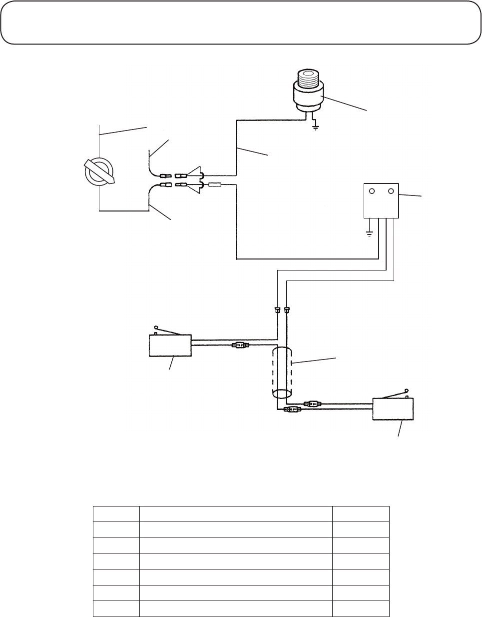
1.47 1.47
ELECTRICAL CIRCUIT DIAGRAM
Black
Black
Stop*Switch
(Mounted*on*handlebar)
Control
Module
Stop*Switch
Wire
Red
Red
Engine*Stop
Switch*Wire
Engine*Stop
Switch
(Mounted*On*
Engine)
Engine*Stop
Switch*Wire
Red
Black
On
OFF
Yellow
Yellow
Switch*Link*Wire
Red
Transmission
Microswitch
Cutter*Clutch
Microswitch
Blue
Red
Blue 4
6
5
1
2
7
Item No. Description Part No.
1 Switch Assembly C/W Keys 510224
2 Control Module Assy 111-5820
4 Cable Assy Microswitch 510116
5 Cutterclutch Microswitch 510068
6 Transmission Microswitch 510069
7 Cable Assy Engine Stop 510227

1.48 1.48
WARRANTY
HAYTER LIMITED Warrants to the original user / purchaser that this unit shall be free from defects in mate-
rial and workmanship for a period of 12 calendar months from the date of delivery. This warranty excludes
proprietary items which have the benefit of the supplying manufacturers warranty.
Engine manufacturers furnish their own warranties and provide services through their authorised network. If
you experience any difficulty please contact your specialist Hayter dealer.
It is the end user / purchasers responsibility to ensure that the service schedule and service record book as
applied are acted upon. HAYTER LIMITED reserve the right to request inspection of a service record book,
where relevant at any reasonable time. Failure to keep the service schedule up to date may invalidate the
warranty. Owners should therefore satisfy themselves that the products are operated and serviced correctly,
particularly where they are operated on a contract or hire basis.
This warranty which is not capable of assignment does not apply to any unit that has been tampered with,
altered, misused or abused and will become invalid if non genuine Hayter parts are fitted. This warranty
does not cover minor adjustments unless they are due to defective materials or workmanship. Consult the own-
ers handbook or your authorised Hayter dealer for assistance when making these
adjustments.
To make a warranty claim contact your authorised Hayter dealer through whom the machine was originally
supplied, indicating the machine serial number and purchase date. Subject to the conditions and exclusions in
this warranty, the authorised dealer will at our option, repair or replace any warranted part within the duration
of the warranty period.
This warranty gives you specific legal rights and is in addition to any statutory rights to which you may be
entitled and your statutory rights are not affected by this warranty. If you need additional information concern-
ing this written warranty or assistance in obtaining services please write or telephone: HAYTER LIMITED,
Service Department, Spellbrook, Bishop’s Stortford, Herts., CM23 4BU. Telephone: ( 01279 ) 723444.

1.49 1.49
NOTES

1.50 1.50
NOTES

1.51 1.51
CUSTOMER INFORMATION
Machine Details
Engine Serial No: . . . . . . . . . . . . . . . . . . . . . . . . . . . . . . . . . . . . . . . . .
Hydrostatic Unit Serial No: . . . . . . . . . . . . . . . . . . . . . . . . . . . . . . . . . . . . . . . . .
Transaxle Serial No: . . . . . . . . . . . . . . . . . . . . . . . . . . . . . . . . . . . . . . . . .
P.U Serial No: . . . . . . . . . . . . . . . . . . . . . . . . . . . . . . . . . . . . . . . . .
Verge Attachment Serial No: . . . . . . . . . . . . . . . . . . . . . . . . . . . . . . . . . . . . . . . . .
Rotary Attachment Serial No: . . . . . . . . . . . . . . . . . . . . . . . . . . . . . . . . . . . . . . . . .
