Hayter Mowers Lt324 Users Manual 924916 (0)
LT324 to the manual 45d195b8-a9eb-4b0a-8039-0b89c6a786bb
2015-02-09
: Hayter-Mowers Hayter-Mowers-Lt324-Users-Manual-564564 hayter-mowers-lt324-users-manual-564564 hayter-mowers pdf
Open the PDF directly: View PDF ![]() .
.
Page Count: 80

English Version
FROM SERIAL NO: 924C001001 MANUAL PART NO: 924916(REV.0.)
Issue: 01.10.04
OPERATOR'S MANUAL
LT324
TRIPLE TURF MOWER
CODE 924C
THIS MANUAL SHOULD BE REGARDED AS PART OF THE
MACHINE, AS IT GIVES ESSENTIAL INFORMATION REGARDING
MACHINE SAFETY, OPERATION AND SPECIFICATIONS.


ATTENTION
THIS SYMBOL MEANS
BE ALERT!
YOUR SAFETY IS INVOLVED
READ THIS MANUAL BEFORE USING THE LT324 MOWER.
IT IS ESSENTIAL THAT OPERATORS STUDY IT FOR THEIR OWN SAFETY.
ALL OPERATORS SHOULD SEEK AND OBTAIN PROFESSIONAL AND
PRACTICAL INSTRUCTIONS ON THE SAFE USE OF THE MOWER. THESE
SERVICES ARE AVAILABLE THROUGH HAYTER LIMITED OR HAYTER APPROVED
COMMERCIAL DEALERS.

924916KG251004
CONTENTS
CONTENTS
SAFETY PRECAUTIONS.
Training.
Preparation.
Operation.
Handling and storage of fluids.
Maintenance and storage.
Decals.
EC CONFORMITY INFORMATION.
Noise levels.
EC Declaration of Conformity.
INTRODUCTION.
SPECIFICATIONS.
Engine.
Transmission system.
Cutterhead drive system.
Cutterhead lift system and steering.
Hydraulic system.
Vehicle specifications.
Operator controls.
Instrumentation.
Weight and dimensions.
Recommended lubricants and hydraulic fluids.
Cutterheads.
OPERATING THE MOWER.
Safety Notice
Operator presence controls.
Identification of controls.
Braking system.
Throttle control.
Travel.
Transport latches.
Differential lock.
Speed Control Pedal.
Operator platform latching mechanism.
Adjustable Steering Column.
Operator Seat.
Warning systems.
Audible warning horn.
Ignition key.
Engine pre-heat indicator light.
Fuel level gauge.
Page No.
1.6 - 1.14
1.6
1.6 - 1.7
1.7 - 1.9
1.10
1.11
1.12 - 1.14
1.15 - 1.16
1.15
1.16
1.17
1.18 - 1.24
1.18
1.19
1.19
1.20
1.20
1.21
1.22
1.22
1.23
1.23
1.24
1.25 - 1.40
1.25
1.25
1.26
1.27
1.27
1.27
1.28
1.28
1.28
1.29
1.30
1.31
1.32
1.32
1.33
1.33
1.33
1.4 1.4

924916KG251004
CONTENTS
CONTENTS Continued.
Hourmeter.
Transmission neutral indicator light.
Cutterdeck drive switch indicator light.
Parking brake indicator light.
Hydraulic return filter indicator light.
Hydraulic transmission filter indicator light.
Cutterhead position control.
Cutterhead drive engagement.
Weight transfer/traction assistance.
Starting the engine.
Stopping the engine.
General operating hints.
Cutterhead general information.
MK3 200mm Fixed Cutterhead.
MK3 254mm Fixed Cutterhead.
MK3 200mm Floating Cutterhead.
Centre Cutterhead Height of Cut Correction Adjustment
MAINTENANCE.
Maintenance
Engine.
Running in period.
Running in period - at first 50 hours.
Daily and before use.
Every 50 hours.
Every 250 hours.
Every 500 hours.
Cutterhead cylinder to bottom blade adjustment.
Cutterhead backlapping.
Cutterhead grinding.
Cutterhead bottom blade replacement.
Raising the mower off the ground.
Towing the mower.
GRASS CUTTING FAULTS.
TROUBLE SHOOTING.
ELECTRICAL CIRCUIT DIAGRAM .
HYDRAULIC CIRCUIT DIAGRAMS.
WARRANTY.
NOTES.
CUSTOMER INFORMATION.
Page No.
1.33
1.34
1.34
1.34
1.34
1.34
1.35
1.35
1.36
1.36 - 1.37
1.37
1.38
1.39
1.40
1.40
1.41
1.41
1.42 - 1.60
1.42 - 1.43
1.44
1.44
1.44 - 1.45
1.46 - 1.49
1.50 - 1.51
1.52
1.53 - 1.55
1.56
1.57
1.58
1.58
1.59
1.60 - 1.61
1.62 - 1.64
1.65 - 1.71
1.72 - 1.73
1.74 - 1.76
1.77
1.78
1.79
1.5 1.5

924916KG251004
SAFETY PRECAUTIONS
TRAINING
Read the instructions carefully. Be familiar with the controls and the proper use of the equipment. Learn
how to stop the mower quickly in an emergency.
Never allow children or people unfamiliar with these instructions to use the mower. Local regulations
may restrict the age of the operator.
Never mow while people, especially children, or pets are nearby.
Keep in mind that the operator or user is responsible for accidents or hazards occurring to other people or
their property.
Do not carry passengers.
All drivers should seek and obtain professional and practical instruction. Such instruction should emphasise:
The need for care and concentration when working with this machine.
The need to slow down when making tight turning manoeuvres. Failure to take adequate care can affect
stability leading to loss of control of the machine particularly when operating in transport mode.
Control of a ride-on-machine sliding on a slope will not be regained by application of the brake.
The main reasons for loss of control are:
- Insufficient wheel grip.
- Being driven too fast.
- Inadequate braking.
- The type of machine is unsuitable for the task.
- Lack of awareness of the effect of ground conditions, especially slopes.
- Incorrect load distribution.
PREPARATION
Check that the machine complies with all applicable regulations, including those in force when used on
the public highway.
While mowing, always wear substantial footwear and long trousers. Do not operate the equipment when
barefoot or wearing open sandals. Eye protection should be worn.
Thoroughly inspect the area where the equipment is to be used and remove all objects which can be
thrown by the machine.
Never operate the machine without first checking that the operator platform latching mechanism is fully
engaged and in good working order, refer - ‘OPERATOR PLATFORM LATCHING MECHANISM’.
READ THIS MANUAL BEFORE USING THE LT324 MOWER, IT IS ESSENTIAL THAT
OPERATORS STUDY IT FOR THEIR OWN SAFETY.
THE FOLLOWING PRECAUTIONS MUST BE TAKEN TO HELP PREVENT ACCIDENTS.
A CAREFUL OPERATOR WHO USES COMMON SENSE IS THE SAFEST OPERATOR.
-
-
-
1.6 1.6

924916KG251004
SAFETY PRECAUTIONS
PREPARATION Continued.
Ensure that the cutterheads are fully raised with the latches and safety locks engaged in position before
transporting the mower.
Replace faulty silencers.
Check the condition of the tyres and ensure that they are inflated to the correct pressures, refer -
SPECIFICATIONS.
This is particularly important if the machine is to be taken on the public highway.
Check that the mower is in good working order, paying particular attention to the brakes and steering.
Also ensure that the forward/reverse speed control pedals move freely to neutral when released.
Before use, always visually inspect to see that the blades, blade bolts and cutting cylinders are not worn
or damaged. Replace worn or damaged components.
Check the mower hydraulic system, particularly the hydraulic hoses, fittings and hose supports. Worn,
crushed or damaged hoses can burst, with risks to health and damage to the machine and surrounding
turf areas.
After refuelling and adding oil to the hydraulic oil tank ensure that the caps are replaced securely.
Check that all linkages, connections and pivot nuts are secure and that wheel nuts are torqued correctly,
refer - SPECIFICATIONS.
Before operating the machine ensure that there are no foreign objects or liquids on the platform or ped-
als - ALWAYS KEEP THE OPERATOR PLATFORM CLEAN/CLEAR.
OPERATION
Do not operate the engine in a confined space where dangerous carbon monoxide fumes can collect.
Mow only in daylight or in good artificial light.
Before attempting to start the engine, engage the parking brake, disengage the cutterhead drive system
and ensure that the forward/reverse speed controls are in the neutral position.
Never operate the machine without first checking that the operator platform latching mechanism is fully
engaged and in good working order, refer - OPERATOR PLATFORM LATCHING MECHANISM.
Stored energy devices are charged when the outer wing units are in transport position. Always operate
the relevant lift controls to provide hydraulic support for the wing units suspensions before attempting
to release the transport latches.
1.7 1.7
924916KG251004
SAFETY PRECAUTIONS
OPERATION Continued.
Do not use on a slope of more than 19 degrees. Where ground conditions are such that there may be a
risk of the mower rolling over, the requirements of SI 1998 No 2306 "Provision and Use of Work
Equipment Regulations" should be considered, refer - INTRODUCTION - Optional Extras.
Ground conditions affect traction. Particular conditions may not permit safe operation on the slope lim-
its stated.
Remember there is no such thing as a "safe" slope. Travel on grass slopes requires particular care. To
guard against overturning or loss of traction when travelling or mowing on a slope:
- Exercise extreme care when changing direction on a slope.
- Do not stop or start suddenly.
- Engage drive slowly.
- Keep machine speed low.
- Avoid tight turns.
- Stay alert for humps, hollows and other hidden hazards.
- Keep away from sharp inclines and steep drops.
- A thorough risk assessment should be carried out by a competent
person before travelling or mowing on a slope.
Never park on a slope.
Ground level
3DA176
19 Degree slope
1.8 1.8

924916KG251004
SAFETY PRECAUTIONS
OPERATION Continued.
Watch out for traffic when crossing or near roadways.
Use extreme caution when reversing.
Disengage the cutterhead drive system before crossing surfaces other than grass.
When using the machine, never direct discharge of material towards bystanders or allow anyone near
the machine while in operation.
Never operate the mower with defective guards, shields or without safety protective devices in place
and in good working order.
Do not change the engine governor settings or overspeed the engine. Operating an engine at excessive
speed may increase the risk of personal injury.
Before leaving the operator's position:
- Disengage the drive to the cutterheads.
- Lift cutterheads to the transport position and securely lock the safety latches
or alternatively lower cutterheads to the ground.
- Change into neutral and set the parking brake.
- Stop the engine and remove the ignition key.
Engage the parking brake, disengage the drive to the cutterheads, stop the engine and remove ignition key :
- Before releasing blockages.
- Before checking, cleaning or working on the mower.
- After striking a foreign object. Inspect the mower for damage and make
repairs before restarting and operating the equipment.
- If the machine starts to vibrate abnormally ( check immediately ).
- Before refuelling.
- Before making cutterhead adjustments.
Disengage the drive to the cutterheads when transporting or not in use.
Reduce the throttle setting during engine run - out.
Never work on the mower when the engine is running.
Always keep feet and hands well away from the cutting cylinders when making adjustments.
Never operate the mower without first checking that the operator platform is securely latched.
1.9 1.9

924916KG251004
SAFETY PRECAUTIONS
HANDLING AND STORAGE OF FLUIDS
Hydraulic Oil
- Avoid contact with eyes and prolonged contact with skin.
- Protective goggles should be worn when pouring.
- Use of gloves or barrier cream is recommended.
- Wash hands thoroughly after contact.
- Store under cover, away from heat and sources of ignition.
Diesel Oil
- Avoid skin and eye contact.
- Wear impervious gloves when regular contact is likely and goggles when there is risk of splashing.
- Wash hands thoroughly after contact.
- Store in a cool dry well ventilated place away from heat and sources of ignition, in vessels specifi-
cally designed for storing fuel oils.
Lubricating Oil
- Avoid skin and eye contact.
- Wear impervious gloves when regular contact is likely and goggles when there is risk of splashing.
- Wash hands thoroughly after contact.
- Store in a cool dry well ventilated place away from heat and sources of ignition.
Anti- Freeze
- Keep away from heat, sparks, and flames.
- Avoid skin and eye contact and breathing vapours.
- Store in a closed container in a cool dry well ventilated area.
1.10 1.10

924916KG251004
SAFETY PRECAUTIONS
MAINTENANCE AND STORAGE
Take care when rotating a cutting cylinder as this can cause other cylinders to rotate.
When the machine is to be parked, stored or left unattended, lift the cutterheads to the transport position
and engage the safety locks or lower the cutterheads to the ground.
Keep all nuts, bolts, and screws tight to be sure the equipment is in safe working condition.
Allow the engine to cool before storing in any enclosure.
To reduce the risk of fire, keep the engine, silencer, fuel tank and battery compartment free of grass, leaves
or excessive grease.
Frequently check fuel lines and fittings for cracks or leaks and replace if necessary.
Replace worn or damaged parts for safety.
Ensure that all safety decals are properly secured and in good condition.
If the fuel tank has to be drained, this should be done outdoors.
Be careful during adjustment of the machine to prevent entrapment of the fingers between moving blades
and fixed parts of the machine.
Never attempt to disconnect any part of the hydraulic system before de-pressurisation. This may be
achieved by lowering all cutterheads to the ground, stopping the engine and removing the ignition key.
Avoid skin or eye contact with hydraulic or diesel fluids. Wear protective clothing.
Leaking fluids under pressure can penetrate the skin or eyes, causing serious injury.
Always use a piece of cardboard or paper when searching for leaks.
Health and Safety at Work Act:
In accordance with section 6 of the Health and Safety at Work Act 1974, the LT324 Mower has been
designed and constructed so that, in so far as is reasonably practical, it will not endanger the safety and
health of those working with it. This is, however, subject to the machine being properly used and
maintained according to the conditions stated in this manual and elsewhere, which have been found
necessary as a result of the research and testing of Hayter Limited.
1.11 1.11
924916KG251004
SAFETY PRECAUTIONS
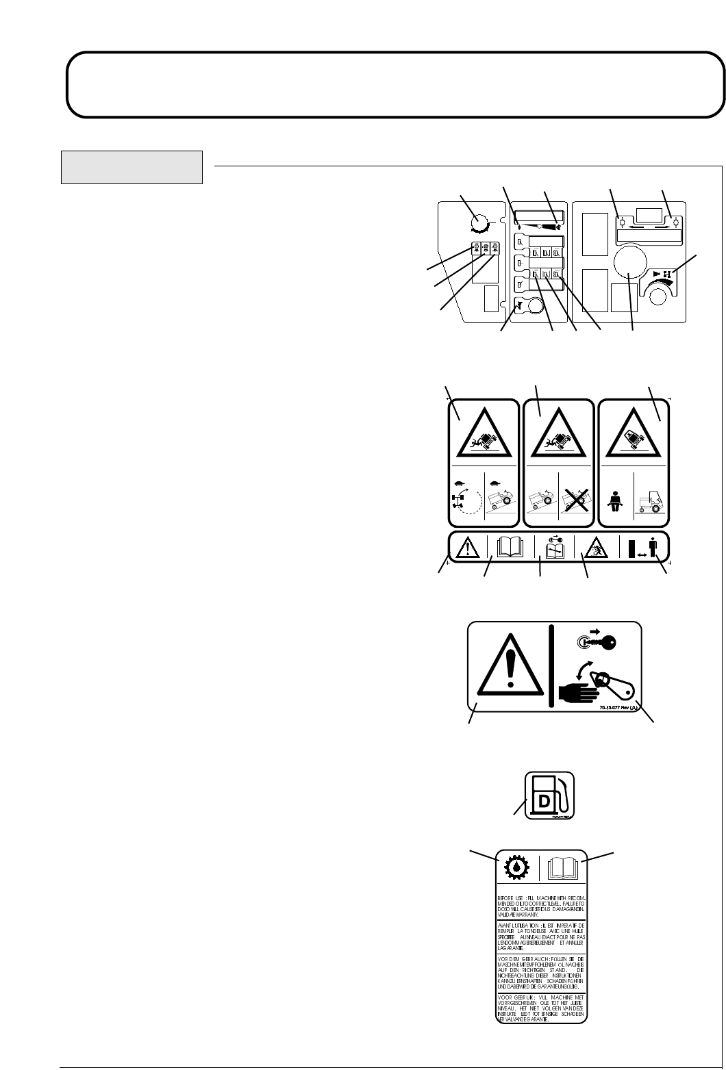
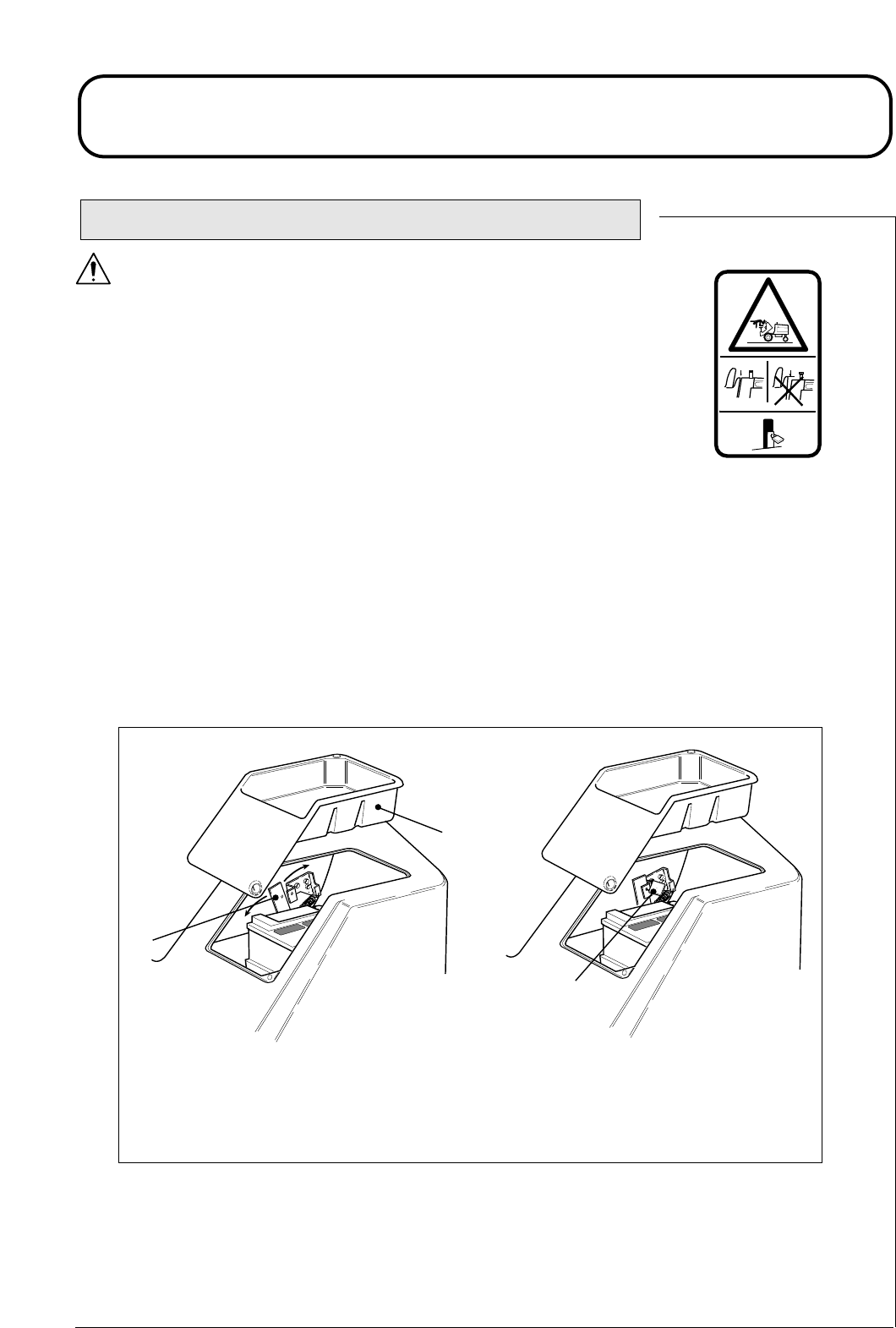
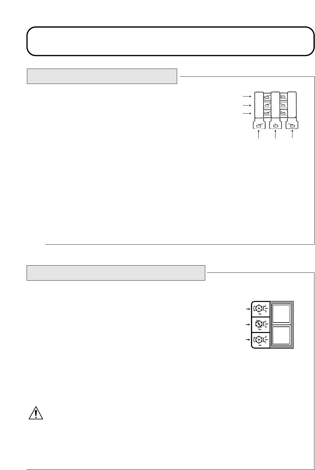
DECALS
Decal - Control Panel Part No: 924898
Location: Control Panel.
a) Ignition Switch
b) Engine Speed - Slow
c) Engine Speed - Fast
d) Parking Brake - Engage
e) Parking Brake - Disengage
f) Weight Transfer - Control
g) Cutters - Reverse
Decal - Inclines Part No: 924857 (1)
Location: Centre Platform.
a) Warning - Travel slowly when turning and on slopes
b) Warning - Maximum Slope without ROPS
c) Warning - Seat belt must be worn with a ROPS fitted.
d) Caution
e) Read Operators Manual
f) Stop engine/Remove ignition key before servicing or
maintenance
g) Beware of flying objects
h) Keep Bystanders Clear
Decal - Danger Latch Part No: 70-13-077
Location: LH / RH / Centre Arms
a) Caution
b) Stop engine/Remove ignition key before releasing or
operating safety latches.
Decal - Diesel Part No: 70-13-07
Location: Fuel Tank
a) Diesel fuel only
Decal - Transmission Oil Part No: 70-13-071
Location: Oil Filler Bracket Mounted Behind Fuel tank.
a) Transmission Oil
b) Read and understand the Operators Manual.
0 - 19°19°+
924857 (1)
IMPOR TANT / WICHTIG / BELANGRIJK
P
P
kg
924898(REV. 0 )
I
II
III
O
1.12 1.12
abcde
f
g
h
i
jklm
h) Cutters - Off
i) Cutters - Forward
j) Horn
k) Cutters - Lift
l) Cutters - Hold
m)Cutters - Drop/Float
n) Hour Meter
abc
de fgh
ab
a
ab
n
924916KG251004
SAFETY PRECAUTIONS
DECALS Continued.
70-13-073 REV (.0.)
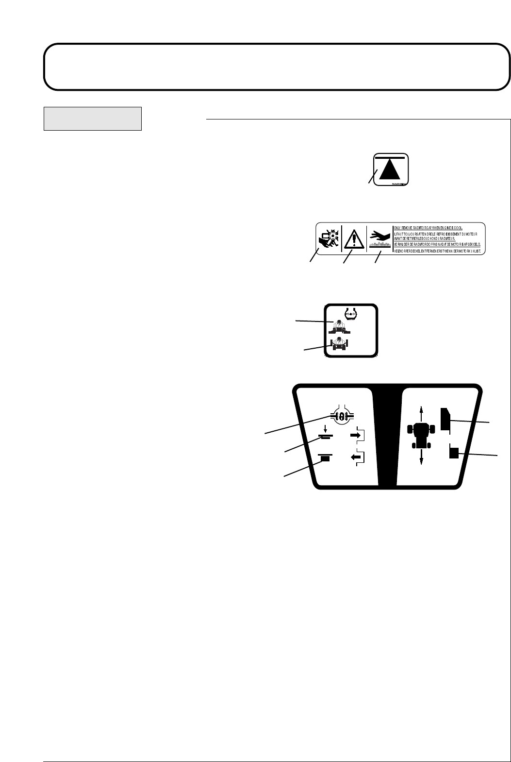
Decal - Jacking / Support Point Part No: 70-13-072
Location: Front Axle - 2 Points
Rear Towing Eye
a) Jacking and Support Point
Decal - Engine Fan / Radiator Part No: 70-13-073
Location: Engine Fan Cowl
a) Danger of Severing Fingers
b) Caution
c) Warning - Hot Surfaces
Decal - Tyre Pressure Part No. 950832
Location: LH/RH Chassis - 4 Places
a) Mowing
b) Road Travel
Decal - Diff Lock / Control Pedal Part No: 924812
Location: Centre Platform.
a) Differential Lock
b) Depress to engage Diff-lock
c) Release to Dis-engage Diff-lock
d) Forward Speed & Directional Control
e) Reverse Speed & Directional Control
950832 Rev.2
0.7 BAR
10 PSI
1.4 BAR
20 PSI
1.13 1.13
a
abc
a
b
924812 REV.(0)
a
b
c
d
e
924916KG251004
SAFETY PRECAUTIONS
DECALS Continued.
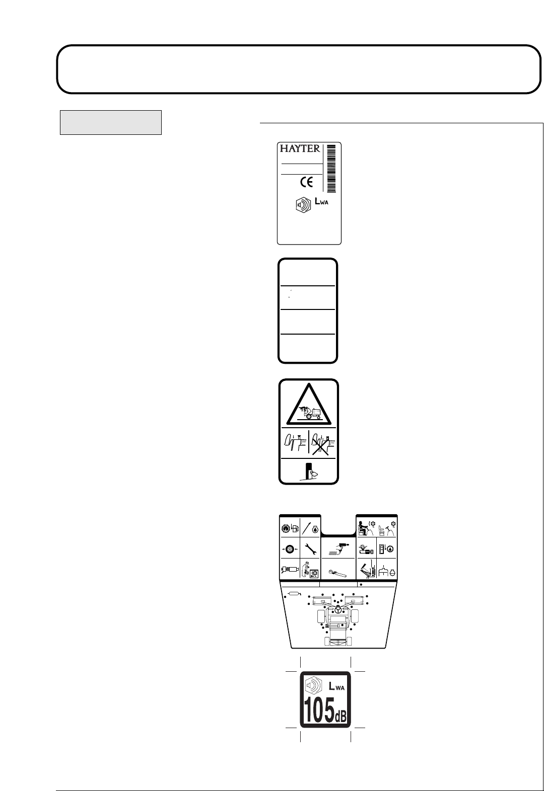
Decal - Serial Number
Location: Rear Bulkhead
Decal - Prevent Platform
Damage
Part No. 924828
Location : Platform, Seatwell.
Decal - Warning Platform Latch
Part No. 924868
Location: Next to Platform Latch
Warning - Prevent Accidents: Ensure plat-
form is correctly seated and the latch is
fully locked before operating the machine.
Decal - Maintenance
Part No. 924882
Location: Underside of Engine Cover next
to Latch.
Decal - Noise
Part No. 922854
Location: Base of Seat on GRP
LT324
- TRIPLE TURF MOWER
SPELLBROOK, BISHOP’S STORTFORD,
HERTS. CM23 4BU. ENGLAND.
Kg 1025
RPM
2800
Serial No: 924C001001
CODE 924C
kW 26.1
2004
105
dB
1.14 1.14
ENGAGE PARKING BRAKE AND
DROP CUTTERHEADS BEFORE
RAISING/LOWERING PLATFORM.
POUR EVITER DES DOMMAGES
,
METTRE LE FREIN DE PARKING ET POSER
LES TETES DE COUPES AVANT DE
BOUGER LA PLATE-FORME.
VOORKOM BESCHADIGING!
ZET
MACHINE OP HANDREM EN LAAT DE
KOOIEN ZAKKEN, VOORDAT HET
BEDIENINGS PLATFORM NAAR VOREN
GEKANTELD OF TERUG GEPLAATST
WORDT.
PREVENT PLATFORM DAMAGE !
924828 REV.0.
..
SCHADEN VERMEIDEN
- PARKBREMSE
FESTSETZEN UND DIE SCHNEIDEINHEITEN
HERUNTERLASSEN BEVOR DIE SITZ-
PLATTFORM GEKIPPT WIRD.
924868 REV .0
DAILY 50 HOURS (WEEKLY)DAILY (IF FITTED)
CLEAN AND INSPECT THE MACHINE.
WHEEL NUT TORQUE
FRONT: 200Nm
REAR: 54Nm
DAILY MAINTENANCE DAILY MAINTENANCE
924882(Rev 1)
GREASE POINTS
30 - 40mm
FUEL
EF
D
FUEL LEVEL
TYRES
AIR CLEANER
ENGINE OIL
FASTENERS
SEAT SWITCH
HOSE LINES HYDRAULIC OIL
RADIATOR/
SCREENS
COOLANT LEVELCUTTERHEADS
50 HOURS MAINTENANCE

924916KG251004
EC CONFORMITY INFORMATION
LT324
- TRIPLE TURF MOWER
SPELLBROOK, BISHOP’S STORTFORD,
HERTS. CM23 4BU. ENGLAND.
Kg 1025
RPM
2800
Serial No: 924C001001
CODE 924C
kW 26.1
2004
105
dB
NOISE LEVELS
Operators Daily Personal Noise Exposure: HAYTER LIMITED have
no control over site conditions, duration of use, state of maintenance or
adjustment of the mower. All of these factors will affect the operator's
daily personal noise exposure level - LEP,d
Under typical working conditions operators could be exposed to a daily
personal noise exposure level in excess of 85 dB (A) LEP,d
Sound pressure level:
The maximum sound pressure level at the operator's position is 84 dB (A)
measured in accordance with European Standard EN836.
Sound power level:
The maximum sound power level is 105 dB(A) measured in accordance
with EC Directive 2000/14/EC.
If ear protection is required, ear protectors with good attenuation in the
63 - 8000 Hz frequency range should be used.
Employers of personnel using this machine are advised to read the 'Noise
at Work Regulations' as the operator's daily personal exposure level could
be above the 'First Action Level'.
1.15 1.15
Wear Hearing
Protection
924916KG251004
EC CONFORMITY INFORMATION
EC DECLARATION OF CONFORMITY
1.16 1.16
VIBRATION INFORMATION
Lawnmower vibration information. Vibration at the operators contact position measured in accordance
with European Standards EN 836.
- steering wheel does not exceed 2.5ms-2
- at seat does not exceed 0.5ms-2
EC DECLARATION OF CONFORMITY
HAYTER LIMITED,
Spellbrook, Bishop’s Stortford, Herts CM23 4BU ENGLAND
declare that the lawnmower:
Type: Ride-On Cylinder Lawnmower
Model Name. LT324 Triple Turf Mower
Model No.: CODE 924C
Cutting Width: 2120 mm
Speed of rotation of cutting device: 1050 rpm
Engine Manufacturer: Kubota
Speed of rotation of engine: 2850 rpm
Complies with the provisions of Directive: 98/37/EC Essential Health & Safety Requirements Relating to the
Design & Construction of Machinery and Safety Components, as amended and the regulations transposed into
national law.
Also Directive 89/336/EEC Electromagnetic Compatibility, as amended and the regulations transposed into
national law.
Also Directive 2000/14/EC Noise emission in the environment by equipment for use outdoors and the regula-
tions transposed into national law.
Procedure applied for the conformity assessment: ANNEX VI, procedure 1.
Notified Body: Sound Research Laboratories Ltd. Holbrook House, Little Waldingfield,
Sudbury, Suffolk, COL0 OTH, ENGLAND
Notified body identification No: 1088
Measured sound power level: 101 dB(A)
Guaranteed sound power level: 105 dB(A)
Complies with harmonised standards: EN 292, EN 836 and EN ISO 14982.
Standards Used: EN292, EN836 and ENISO14982
Signed Date: 01.10.04
Technical Documentation Kept at:
HAYTER LIMITED,
S.A. Maryniak Spellbrook, Bishop’s Stortford,
(Technical Director) Herts CM23 4BU ENGLAND

924916KG251004
INTRODUCTION
Fixed
Heads
Cutterhead Number of bladesCylinder diameter
MK3 Cutterhead 200mm 4, 6, 8, 10. ✔✔
Floating Heads with smooth
or grooved front rollers
254mm 4, 6 ✔
1.17 1.17
INTRODUCTION
The Hayter LT324 Triple Turf Mower is a diesel engine powered self propelled machine with hydraulic
systems for ground drive, cutterhead drives and steering. The machine operates in two wheel drive with
automatic four wheel drive on demand. A differential lock function may be selected. The transmission
system is converted automatically to engage drive to all 4 wheels when the machine speed decreases as
a result of front wheel traction slip. 2WD is automatically re-engaged when traction slip is reduced.
The Hayter LT324 Triple Turf Mower is a precision built machine designed solely for cutting grass and
similar low lying ground vegetation within the limitations stated in this manual. Use in any other way
is considered as contrary to the intended use. Compliance with and strict adherence to the conditions
of operation, service and repair as specified in this Operators Manual also constitute essential elements
of the intended use. The way in which this machine is operated and maintained will have a profound
effect on its performance and reliability.
This manual contains advice on the Hayter LT324 Triple Turf Mower which should be operated, serviced
and repaired only by persons who are familiar with its particular characteristics and who are acquainted
with the relevant safety procedures.
The safety precautions listed herein and all other generally recognised regulations on safety and all road
traffic regulations must be observed at all times.
Any arbitrary modifications carried out to this machine may relieve Hayter Limited of liability for any
resulting damage or injury.
In the pursuit of continuous product development Hayter Limited reserve the right to alter specifications
without notice.
Cutterhead Variants: The Hayter LT324 can be fitted with a range of cutterhead configurations and
optional extras:
Optional Extras:
Beacon Kit - Amber flashing warning light.
Lighting Kit - Complies with EC traffic regulations.
R.O.P.S ( Roll Over Protective Structure ) 2 post design.
Cab R.O.P.S. - Full weather protection and roll - over protection.
A R.O.P.S. must be fitted to ensure operator safety when working on slopes in excess of 19
degrees, refer - SAFETY PRECAUTIONS.
When fitting optional extra kits to the mower be sure to fix the serial number decal supplied with the
kit to the rear bulkhead underneath the engine cover. This will help the Hayter spare parts department
to supply the correct spare parts throughout the service life of the mower.
Left and Right: Throughout this manual the terms 'Left' and 'Right' refer to the machine when looking
in the direction of forward travel.

924916KG251004
SPECIFICATIONS
SPECIFICATIONS
ALL FIGURES ARE NOMINALLY QUOTED AT THE RATED ENGINE SPEED OF 2800 RPM
UNLESS OTHERWISE STATED.
ENGINE
Type:
Power Rating:
Capacity:
Air Cleaner:
Cooling System:
Battery:
Alternator:
Starter:
Cold Starting:
Idle Speed:
Fuel Type:
IMPORTANT: PREVENT DAMAGE - for further information regarding the engine, refer to -
ENGINE MANUAL .
Kubota V1505 -BB.
4 Cylinders in line.
35hp (26.1 kw) @ 2800 RPM.
DIN 70020.
1498 cc.
Clean air drawn through screened air intake in-front of
radiator via a cyclonic air cleaner with built in pre-cleaner.
Water-Cooled.
12V. 480 Amps S.A.E.
40 Amps.
1.2 KW Electric.
Glow Plug.
1250(+50) R.P.M.
Diesel.
1.18 1.18

924916KG251004
SPECIFICATIONS
TRANSMISSION SYSTEM
Drive Type:
Pump:
Wheel Motors:
Differential Lock:
Drive:
Relief Valve Setting:
CUTTERHEAD DRIVE SYSTEM
Drive Type:
Pump:
Delivery Rate:
Cutterhead Motors:
Control:
Relief Valve Setting:
Hydraulic.
Variable displacement hydraulic piston pump with integral charge
pump and pedal control.
Front Axle - Radial piston, fixed displacement, with integral disc
brake (pressure released).
Rear Axle - Gear motor, fixed displacement.
Electro - hydraulic control valve with pedal control.
2WD (front axle) with differential lock (selectable) and automatic
4WD on demand (forward & reverse).
Main service relief 300 bar (4350 psi) differential.
Charge pressure relief 18.5 bar (268 psi) differential.
Hydraulic.
Hydraulic gear type.
31 Litres per minute.
Hydraulic gear type, reversible, pressure balanced with integral
differential pressure sensing relief check valve. Direct drive.
Electro-hydraulic.
Automatic diverter valve safety cut-off.
250 bar (3625 psi) differential.
1.19 1.19

924916KG251004
SPECIFICATIONS
CUTTERHEAD LIFT SYSTEM AND STEERING
Drive Type:
Pump:
Delivery Rate:
Steering:
Cutterhead Lift Control:
Relief Valve:
Weight Transfer:
HYDRAULIC SYSTEM
Hydraulic Oil Type:
Capacity:
Cooling:
Suction Line Filtration:
Return line Filtration:
Transmission Filtration:
Cleanliness Level:
Maximum Oil Temperature:
Hydraulic.
Hydraulic gear pump with integral relief valve.
11 Litres per minute.
Power beyond hydrostatic steering valve with priority flow to
steering and auxiliary flow to cutterhead lift system. Manual
emergency steering.
Mechanical-hydraulic.
105 bar (1522 psi).
Variable hydraulic applied weight transfer acting on all
cutterheads.
Refer - RECOMMENDED LUBRICANTS
AND HYDRAULIC FLUIDS.
40 Litres.
Forced air finned tube oil cooler.
125 micron no bypass mesh filter.
10 micron with 2 bar (29 psi) bypass check valve.
10 micron no bypass pressure filter.
ISO Code 18/13 or better (ISO 4406)
1300 - 2500 Particles/ml<15μ
40 - 80 Particles/ml>15μ
950C
1.20 1.20

924916KG251004
SPECIFICATIONS
Wheel Nut Torque Setting: Front axle 200Nm
Rear axle 54Nm
Service Brakes: Closed loop hydrostatic service braking operating on drive wheels only.
Parking Brake: Lever operated oil immersed disc brakes on front wheels only. Pressurised hydraulic oil
release with mechanical override for emergency towing purposes.
Ground Clearance: 180mm at 13mm cut height and with cutterheads raised.
Steering: Hydrostatic rear wheel steering, emergency manual steering.
Features: Tilting operator platform.
Lockable engine cover.
Adjustable suspension seat with folding arms.
Adjustable steering column.
Cutterhead parking latches with safety locks.
Backlapping facility.
Differential lock ( selectable ).
Engine coolant and hydraulic oil overheat audible warning (horn).
Variable cutterhead weight transfer/traction assistance.
2WD with 4WD on demand (forward & reverse).
Hydraulic oil filter blocked telltales on control panel.
Safety Features: Neutral start interlock on transmission pump, parking brake and
cutterhead drive switch.
Operator presence control (seat switch).
VEHICLE SPECIFICATIONS
Travel Speed: 0-22 km/hr (0-14 mph) forward.
0-11 km/hr (0-7 mph) reverse.
Tyres Tyre Type
Front axle
Rear axle
0.7 bar
(10 psi )
0.7 bar
(10 psi).
1.4 bar
(20 psi)
1.4 bar
(20 psi)
Recommended Tyre Pressures
Turf Conditions Max Pressure
Road Conditions
26 x 12 - 12 4 ply
Trelleborg turf pattern.
18 x 9.5 - 8 6 ply
Dico turf pattern.
1.7 bar
(25 psi)
1.7 bar
(25 psi)
1.21 1.21

924916KG251004
SPECIFICATIONS
Automotive padded steering wheel.
Electrical switch (forward - off - reverse).
Hand operated lever.
Hand operated lever.
Forward and reverse foot pedal.
Key start, shut - off and engine preheat.
Foot pedal.
Hand operated lever.
Button switch.
Hand wheel.
Engine oil pressure.
Battery charge.
Engine coolant temperature.
Hydraulic transmission oil temperature.
Digital hour meter.
Fuel level.
Hydraulic oil level sight glass.
Engine pre-heat.
Hydraulic return filter blocked.
Hydraulic transmission filter blocked.
Cutterhead drive switch off.
Parking brake engaged.
Transmission neutral.
Steering:
Cylinder Drive:
Engine Speed:
Parking Brake:
Forward and Reverse:
Ignition:
Differential Lock:
Cutterhead Position:
Horn:
Weight Transfer:
OPERATOR CONTROLS
INSTRUMENTATION
Warning Lights:
Gauges:
Indicator Lights:
1.22 1.22

924916KG251004
SPECIFICATIONS
Wheel Base:
Working Width:
Cutting Width:
Transport Width:
Overall Length:
Overall Height:
Approx. Working Weight:
WEIGHT AND DIMENSIONS
RECOMMENDED LUBRICANTS AND HYDRAULIC FLUIDS
Grease Points: A good quality medium grease.
Engine: Refer - ENGINE OPERATORS MANUAL.
Hydraulic System:
Should you be in any doubt please contact your Hayter dealer. Using incorrect grades will cause
premature wear of hydraulic components and invalidate warranty.
1440 mm.
2300 mm.
2120 mm.
1575 mm at 13mm height of cut.
2690 mm.
1520 mm.
1250 kg less operator, no options fitted.
(The exact weight depends on the cutterhead configuration).
Ambient Temperature Range
0 - 30 C (32 - 86 F)
I S O viscosity grade
46 hydraulic oil.
OO15 - 40 C (59 - 104 F)
I S O viscosity grade
68 hydraulic oil.
OO
1.23 1.23

924916KG251004
SPECIFICATIONS
CUTTERHEADS
Cutting Width:
Cylinder Diameter:
Cylinder Speed:
Height of Cut:
Number of Blades:
Smooth Rear Roller:
Smooth Front Roller:
Grooved Front Roller:
Configuration:
MK3 200mm Cutterhead
762 mm.
200 mm.
1050 rpm approx.
12 - 80 mm.
4, 6, 8, 10
Standard.
Optional.
Optional.
Fixed / Floating.
MK3 254mm Cutterhead
762 mm.
254 mm.
1050 rpm approx.
12 - 80 mm.
4, 6
Standard.
-
-
Fixed
1.24 1.24

924916KG251004
OPERATING THE MOWER
OPERATOR PRESENCE CONTROLS
Cutting Cylinder Drive Lockout: Drive to the cutting cylinders is only possible when the operator is
seated. If the operator raises off the seat for a period of more than one second, a switch is activated and
drive to the cutting cylinders is automatically disengaged. To re-engage drive to the cutting cylinders, the
operator must return to the seat, then operate the cutterhead drive switch to the ‘OFF’ position before
moving it back to the ‘ON’ position. If the operator rises off the seat for a brief moment during normal
work, drive to the cutting cylinders is not affected.
The engine can only be started with the cutterhead drive switch in the ‘OFF’ position.
Engine Start Lockout: The engine can only be started when the forward/reverse travel pedal is released
to the 'NEUTRAL' position, the cutterhead drive switch is in the ‘OFF’ position and the parking brake is
engaged. When these circumstances are satisfied, switches are activated permitting the engine to be start-
ed.
Engine Run Interlock: Once the engine is started the operator must be seated before the parking brake is
released for the engine to continue to run.
With the engine running and the machine moving with the travel pedal depressed, the engine will contin-
ue to run when the operator rises from the seat. If the travel pedal is then allowed to return to neutral the
engine will cut out.
WARNING: PREVENT ACCIDENTS - Do not operate the turf mower if the operator presence
controls are defective in any way. ALWAYS replace faulty parts and check that they function
correctly before operating the mower.
SAFETY NOTICE
WARNING: PREVENT ACCIDENTS - Before operating the mower it is essential that;
- The operator reads and understands this manual.
- The operator platform latching mechanism is fully engaged and in good
working order, refer - OPERATOR PLATFORM LATCHING MECHANISM.
- The daily maintenance checks have been properly carried out and the
mower is in good working order.
- The operator should wear safety clothing and eye protection. Failure to do
so could result in risk to health and safety.
- The area where the equipment is to be used is inspected and all objects
which may be thrown by the machine are removed.
Operate safely on slopes;
It is essential to follow safe working practices when working on slopes. In
order to avoid potentially hazardous situations, it is essential that the operator
understands and observes the relevant safety precautions listed in this manual,
refer - ‘SAFETY PRECAUTIONS’.
1.25 1.25
924916KG251004
OPERATING THE MOWER
1.
2.
3.
4.
5.
6.
7.
8.
9.
10.
11.
12.
13.
14.
15.
16.
17.
18.
19.
20.
21.
22.
23.
24.
25.
26.
27.
28.
29.
30.
31.
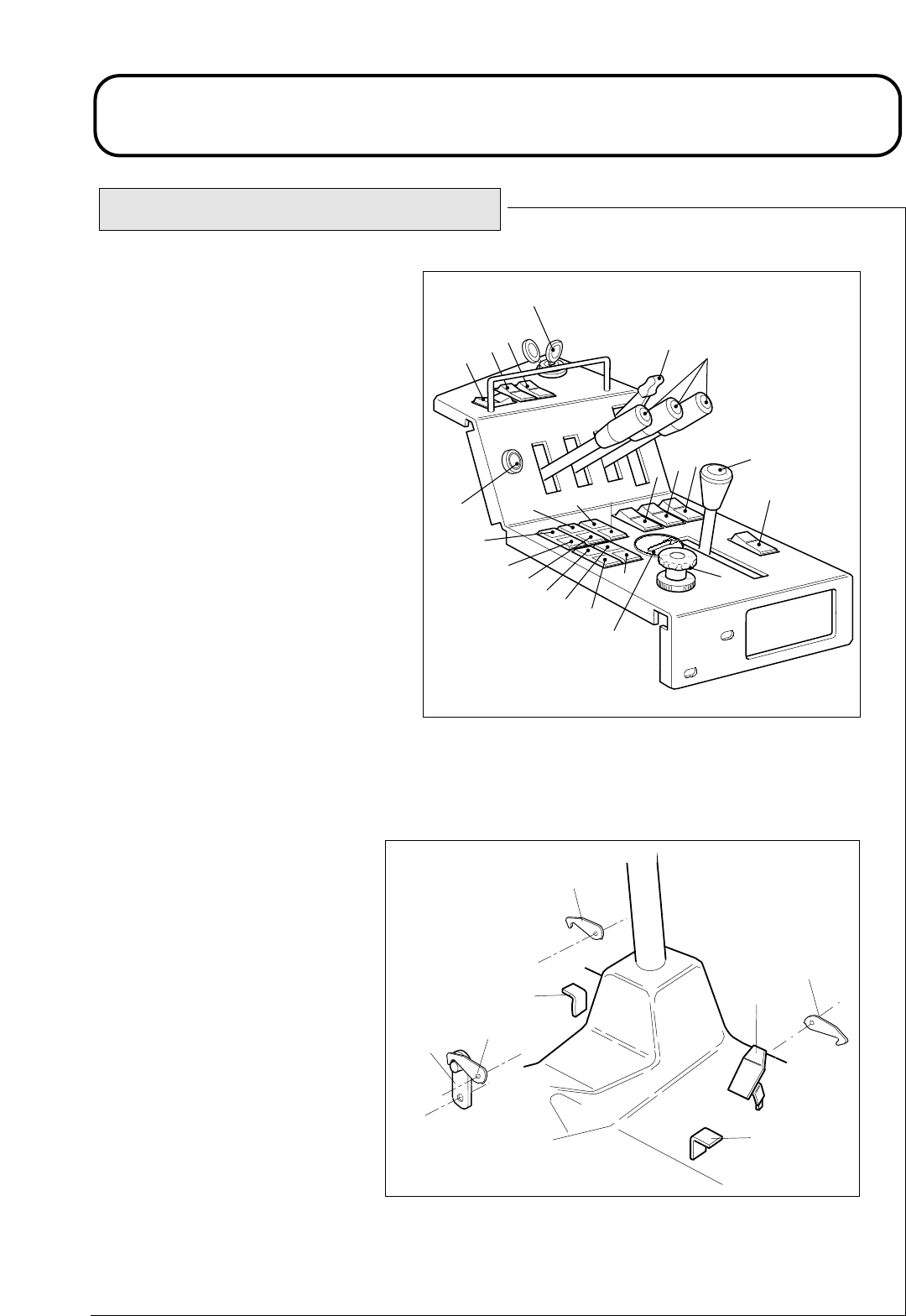
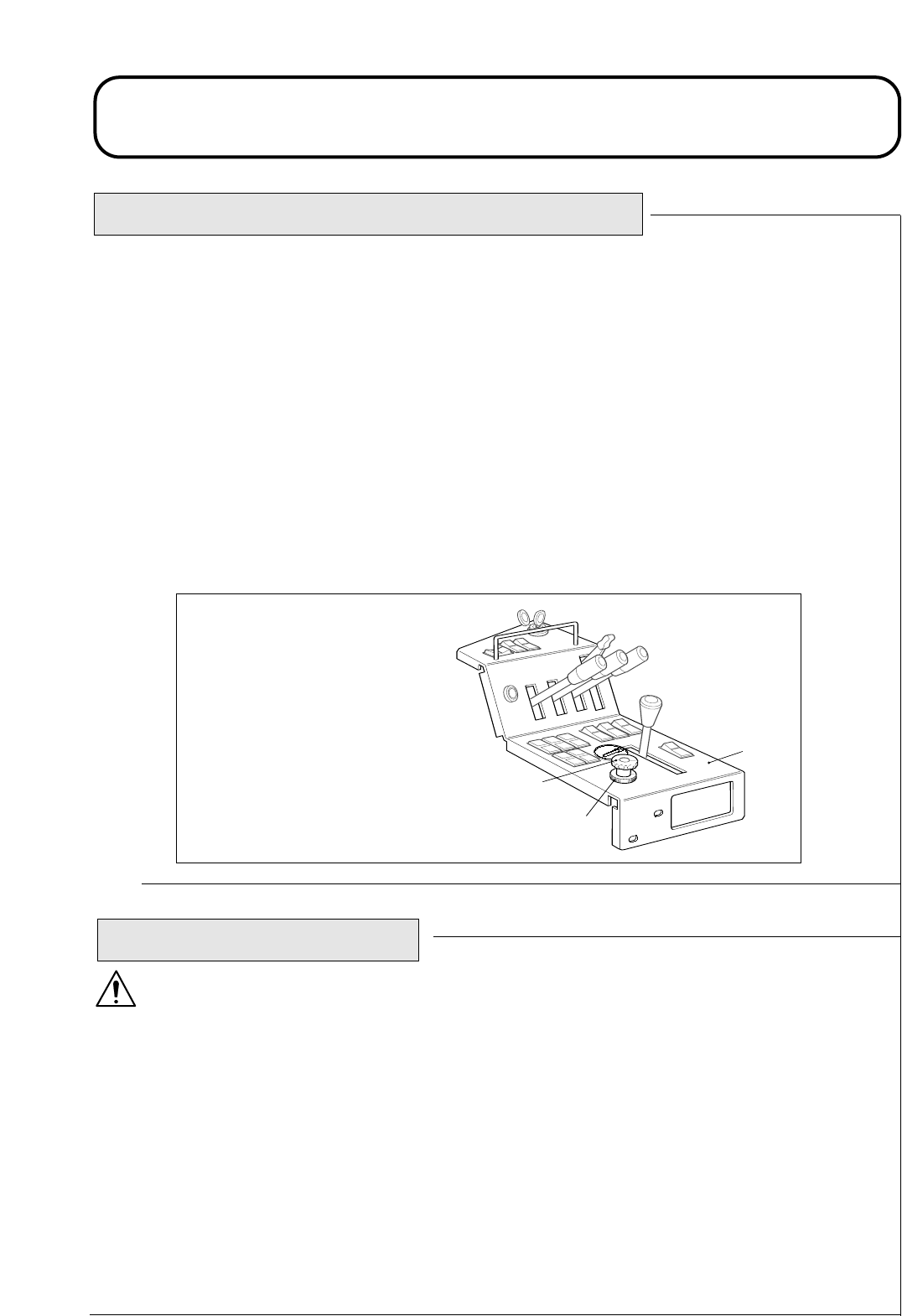
Parking brake lever.
Lighting switch
(supplied with lighting kit).
Warning beacon switch
(supplied with beacon kit).
Hazard warning switch
(supplied with lighting kit).
Cutterhead position controls.
Throttle control lever.
Ignition key.
Cutterhead drive switch.
Dip beam / main beam light switch
(supplied with lighting kit).
Direction indicator switch
(supplied with lighting kit).
Horn button.
Transmission oil filter indicator.
Oil pressure indicator.
Transmission temperature indicator.
Return oil filter indicator.
Battery warning indicator.
Engine temperature warning
indicator.
Glow plug indicator.
Cutterhead drive off indicator.
Parking brake indicator.
Transmission neutral indicator.
Weight transfer control.
Wash / wipe switch
(supplied with cab kit).
Hour Meter
Left hand cutterhead safety latch.
Right hand cutterhead safety latch.
Centre cutterhead transport latch.
Reverse travel pedal.
Forward travel pedal.
Differential lock pedal.
Centre cutterhead safety latch.
4A924A02 (1)
1
2
5
6
10 9
4
7
8
11 14
13
12
15
16 18 19 20
21
17
22
3
23
24
HOURS
QUARTZ
CURTIS
1
10
1D924S04A (1)
31
27
25
29
26
28
30
IDENTIFICATION OF CONTROLS
1.26 1.26
924916KG251004
OPERATING THE MOWER
BRAKING SYSTEM
Parking brake : Move the parking brake lever to its rear position to engage the
parking brake. Do not operate the mower with the parking brake engaged.
WARNING : PREVENT ACCIDENTS - The parking brake operates on the front wheels only. Do not
park the mower on a slope.
Service brakes : Service braking is achieved by the hydraulic transmission system. When the forward or
reverse travel pedals are released or the engine speed reduced, service braking becomes effective and trav-
el speed is automatically reduced. To increase the braking effect, push the transmission pedal into the neu-
tral position. Service braking is effective on the front wheels only.
WARNING : PREVENT ACCIDENTS - The service braking system will not hold the mower at a stand-
still. ALWAYS ensure the parking brake is engaged to park the mower at a standstill.
Emergency braking : In the event of service brake failure, turn the ignition off to bring the mower to a
standstill.
WARNING: PREVENT ACCIDENTS - Take care when operating the emergency braking system.
Remain seated and hold on to the steering wheel to prevent ejection from the mower caused by the
front wheel brakes being applied suddenly when travelling.
THROTTLE CONTROL
Operate the throttle control in a forward direction to increase the engine speed.
Operate the throttle control in a rearward direction to reduce engine speed.
Note that the engine speed dictates the speed of the other functions, i.e. travel, cut-
ting cylinder, position controls.
TRAVEL
Forward travel: Depress the forward travel pedal to increase forward travel
speed. Release the pedal to reduce speed.
Reverse travel: Depress the reverse travel pedal to increase reverse travel speed.
Release the pedal to reduce speed.
Stop (Neutral): Release the forward or reverse travel pedal.
P
1.27 1.27
Parking brake engaged
SlowFast
Engine Speed Engine Speed
Fast Slow
924916KG251004
OPERATING THE MOWER
1D924P07A
DIFFERENTIAL LOCK
WARNING : PREVENT ACCIDENTS - Do not engage the
differential lock at high speed. The turning circle will increase with
the differential lock engaged.
The differential lock operates in both ‘forwards’ and ‘reverse’ and can be
engaged whilst the mower is travelling slowly. Engage the
differential lock to prevent excessive wheel spin when the drive wheels
lose traction. Engine power demand increases when the differential lock
is engaged. Prevent excessive power requirements by operating with
differential lock at SLOW speed.
Engaging differential lock: Depress the differential lock pedal.
Disengaging differential lock: Release the differential lock pedal.
TRANSPORT LATCHES
WARNING : PREVENT ACCIDENTS - ALWAYS raise the
cutterheads to the transport position and secure with the transport
latches and safety locks when travelling between work areas.
Front cutterhead transport latches:
Centre cutterhead transport latch:
1
2
1. Transport latch.
2. Safety lock.
1.28 1.28
SPEED CONTROL PEDAL
The speed control pedal can be adjusted to provide two speed ranges.
Securing the speed control cable through hole ‘A’ will provide 0-22 km/hr
(0-14 mph) forward and 0-11 km/hr (0-7 mph) reverse. Securing the cable
through hole ‘B’ will provide 0-19 km/hr (0-12 mph) forward and
0-8 km/hr (0-5 mph) reverse.
WARNING: PREVENT ACCIDENTS - Ensure that the control cable
is securely fastened to the speed control pedal. Ensure that both the
cable and pedal articulate freely through their full range of travel
and that the mechanism freely returns to neutral when released.
WARNING: PREVENT ACCIDENTS - Ensure that the control cable
is correctly routed underneath the operator platform such that it is
clear of any obstructions and impediments to its operation.
A
B
3D924S03A
Section through
operator platform
Speed control cable
Speed
control pedal
1
1
2
2
924916KG251004
OPERATING THE MOWER
WARNING: PREVENT ACCIDENTS - Never operate the mower
without first checking that the operator platform latching mechanism
is fully engaged and in good working order. Check behind the seat and
ensure that the top of the platform is flush with the top of the fuel tank.
Also check beneath the tool tray and ensure that the release lever is
padlocked in the correct position.
IMPORTANT: PREVENT DAMAGE - Engage the parking brake and
lower the cutterheads to the ground. Remove ignition key and close
ignition cover before raising or lowering the platform.
Releasing the platform: Release and remove the tool tray from the left hand side of the platform.
Release the padlock securing the locking latch handle with the key provided. Move the locking latch
handle towards the front of the mower (position A) until the latch hooks clear the locking bar and raise
the platform. The gas spring will provide assistance.
Securing the platform: Lower the platform carefully. The gas spring will provide assistance. Move the
locking latch handle towards the front of the mower (position A) as the platform nears the fully lowered
position. This will ensure that the latch hooks clear the locking bar. Fully lower the platform and move
the locking handle towards the rear of the mower (Position B) until the latch hooks fully engage the
locking bar. Replace the padlock in order to secure the locking latch handle in place.
OPERATOR PLATFORM LATCHING MECHANISM
1.29 1.29
2
1
3D924S002A
A
B
1. Tool tray
2. Locking latch handle
3. Padlock
A. Releasing
B. Securing
3D924S004A
3
924868 REV .0
924916KG251004
OPERATING THE MOWER
WARNING: PREVENT ACCIDENTS - Never operate the mower without first checking that the
steering column adjuster mechanism is in good working order and that, once adjusted and locked,
the steering wheel remains securely in position.
WARNING: PREVENT ACCIDENTS - Adjustment of the steering wheel and steering column
should only be carried out when the mower is at a standstill with the parking brake engaged.
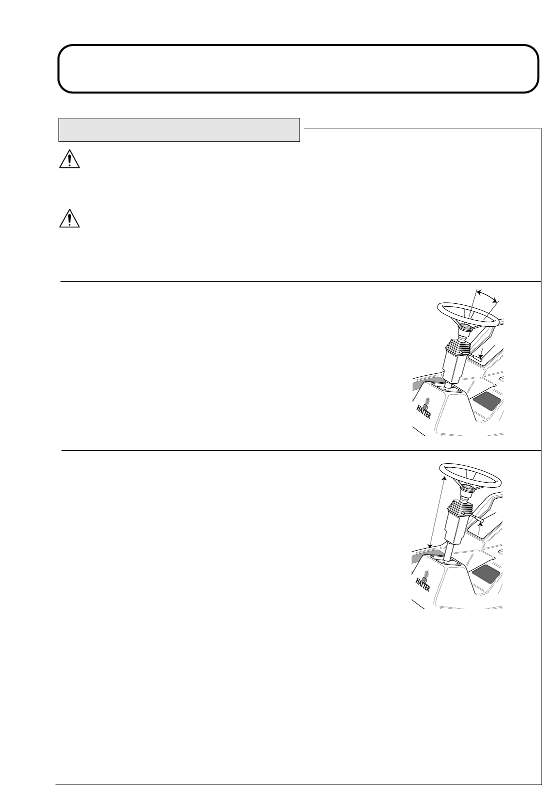
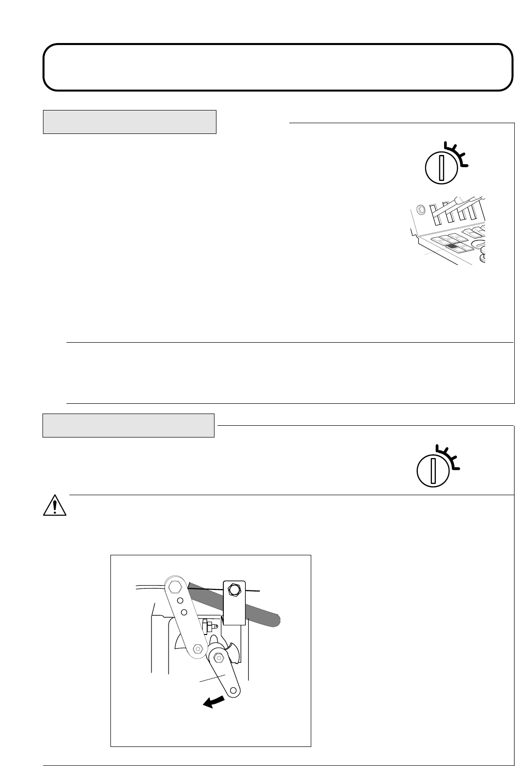
Adjusting the angle of inclination of the steering wheel: Move lever ‘A’
downwards to adjust the angle of steering wheel. Release the lever to lock
the steering wheel in position.
Adjusting the length of the steering column: Move the lever ‘A’ upwards
to adjust the length of the steering column. Release the lever to lock the
steering column in position.
ADJUSTABLE STEERING COLUMN
1.30 1.30
A
1D924T1
A
1D924T2
924916KG251004
OPERATING THE MOWER
WARNING: PREVENT ACCIDENTS - Never operate the mower without first checking that the
operator seat mechanisms are in good working order and that, once adjusted and locked, the seat
remains securely in position.
WARNING: PREVENT ACCIDENTS - Adjustment of the seat mechanisms should only be carried
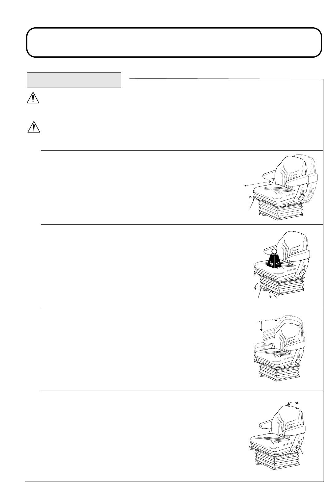
out when the mower is at a standstill with the parking brake engaged.
Fore/Aft Adjustment: Move lever ‘B’ upwards to adjust the Fore/Aft posi-
tion of the seat. Release the lever to lock the seat in position.
Operator weight adjustment: Rotate handle ‘C’ clockwise as shown to
increase suspension stiffness and counter-clockwise to decrease. Dial ‘D’
indicates when the optimum suspension adjustment has been set according
to operator weight (kg).
Height adjustment: Manually lift the seat for incremental height adjustment.
To lower lift the seat to beyond its highest setting, then allow it to drop to the
lowest setting.
Backrest adjustment: Pull handle ‘E’ outwards to adjust the seat backrest
angle. Release the handle to lock the seat backrest in position.
OPERATOR SEAT
1.31 1.31
CD
CW
CCW
1D924T4
1D924T6
E
B
1D924T3
1D924T5

924916KG251004
OPERATING THE MOWER
WARNING SYSTEMS
Engine coolant overheating warning : The engine coolant warning
light illuminates and the horn is actuated.
Hydraulic oil overheating warning : The hydraulic oil warning light
illuminates and the horn is actuated when the hydraulic oil in the reser-
voir exceeds 95˚C approx.
Low battery charge warning : The battery charge warning light illuminates.
Low engine oil pressure warning light : The engine oil pressure warning
light illuminates.
AUDIBLE WARNING HORN
Depress the horn button to provide an audible warning.
IMPORTANT : PREVENT DAMAGE - The horn is automatically
actuated when an engine coolant or hydraulic oil overheat condition
occurs. STOP the engine immediately and effect remedial action
before restarting.
1.32 1.32
924916KG251004
OPERATING THE MOWER
E = Empty.
F = Full.
IGNITION KEY
0= Engine off.
I = Engine run / Auxiliary on.
II = Engine pre-heat.
III = Engine start.
WARNING : PREVENT ACCIDENTS - Always remove the ignition key when the mower is not in
use.
IMPORTANT : PREVENT DAMAGE - Always fit the protective cap when the ignition key is
removed to prevent ingress of dirt and moisture from damaging the mechanism.
ENGINE PRE-HEAT INDICATOR LIGHT
Turn the ignition key to position II. The engine pre-heat indicator light
will illuminate.When the correct pre-heat temperature is achieved the
indicator light will switch off. When this condition is achieved turn the
ignition key to position III to start the engine.
IMPORTANT: PREVENT DAMAGE. Attempting to start a cold
engine before the pre-heat indicator light switches off can cause
unnecessary wear to the battery.
FUEL LEVEL GAUGE
Displays fuel tank level.
HOURMETER
Displays engine running hours.
I
II
III
O
3 4 5 5 9
FUEL
EF
D
WS023
WS044
1.33 1.33

924916KG251004
1.34 1.34
OPERATING THE MOWER
TRANSMISSION NEUTRAL INDICATOR LIGHT
Illuminates when the travel control pedal is in the
neutral position and the ignition key is turned to position ‘I’.
Note: The parking brake must be engaged for the transmission neutral indica-
tor light to illuminate.
CUTTERDECK DRIVE SWITCH INDICATOR LIGHT
Illuminates when the cutterdeck drive switch is in the ‘off’ position and the ignition
key is turned to position ‘I’.
PARKING BRAKE INDICATOR LIGHT
Illuminates when the parking brake is engaged and the ignition key is turned to posi-
tion 'I’.
HYDRAULIC RETURN FILTER INDICATOR LIGHT
Illuminates when the return filter element is blocked.
Note: The engine must be running for the hydraulic return filter indicator light
to illuminate. The indicator light may illuminate briefly when the hydraulic oil
is cold.
HYDRAULIC TRANSMISSION FILTER INDICATOR LIGHT
Illuminates when the transmission filter element is blocked.
Note: The engine must be running for the hydraulic return filter indicator light
to illuminate. The indicator light may illuminate briefly when the hydraulic oil
is cold.
N
WS041
WS046
WS045
P
WS043
WS042
924916KG251004
OPERATING THE MOWER
CUTTERHEAD POSITION CONTROL
The cutterheads may be raised or lowered independently using the bank of 3
lift control levers.
To lower the cutterheads, operate the lift control levers in a downward
direction until locked in position 1. If the cutterhead drive switch is in the
‘ON’ position, the cylinder drive will engage when the cutterheads are
approximately 300mm above ground level.
IMPORTANT: PREVENT DAMAGE - The lift control levers must be
locked in position 1 whilst mowing. NEVER mow with the lift control
levers in position 2 (neutral).
To raise the cutterheads, operate the lift control levers in an upward direction
and hold in position 3. If the cutterhead drive switch is in the ‘ON’ position
the cylinder drive will disengage when the cutterheads are approximately
300mm above ground level. Release the lift control levers when the
cutterheads are at the required height. The control levers will automatically
return to position 2 (neutral).
CUTTERHEAD DRIVE ENGAGEMENT
The cutterhead drive can be engaged only when the operator is seated
correctly, refer - OPERATOR PRESENCE CONTROLS.
Release the cutterhead latches. Operate the cutterhead position controls to
the down / float position and lower all cutterheads to the ground ready for
mowing.
Forward rotation cutterhead drive engagement : Operate the cutterhead
drive switch to the 'Forward' position.
Reverse rotation cutterhead drive engagement : Operate the cutterhead
drive switch to the 'Reverse' position.
To disengage all cutterhead drives : Operate the cutterhead drive switch to
the 'Off' position.
WARNING : PREVENT ACCIDENTS - Refer OPERATOR
PRESENCE CONTROLS for additional information.
1. Forward.
2. Off.
3. Reverse.
1. Down / float.
2. Neutral.
3. Raise.
4. Left hand cutterhead
5. Centre cutterhead.
6. Right hand cutterhead
WS047
1
2
3
4A953B03A
1
2
3
456
1.35 1.35
924916KG251004
OPERATING THE MOWER
WEIGHT TRANSFER / TRACTION ASSISTANCE
A variable hydraulic weight transfer system is provided for improving tyre grip with the grass surface -
‘Traction Assistance’.
Hydraulic pressure in the cutterhead lift system provides a lifting force which reduces cutterhead weight
on the ground and transfers the weight as a downward force onto the mower’s tyres. This action is
known as ‘Weight Transfer’.
To engage weight transfer: The amount of weight transfer can be varied to suit operating conditions by
rotating the weight transfer hand wheel as follows;
Release the lock wheel underneath the hand wheel 1/2 turn anti-clockwise and hold.
Rotate the hand wheel: - Anti-clockwise to reduce weight transfer.
- Clockwise to increase weight transfer.
Tighten the lock wheel.
STARTING THE ENGINE
WARNING: PREVENT ACCIDENTS - Before starting the engine check that ;
- The area is clear of bystanders.
- The cutterhead drive is disengaged.
- The parking brake is engaged.
- The travel control pedals are in neutral.
- You have read and understood the SAFETY PRECAUTIONS section in this
manual.
This machine is fitted with an Engine Start Lockout, refer - OPERATOR PRESENCE
CONTROLS.
HOURS
QUARTZ
CURTIS
1
10
4A922A02A
1
2
3
1. Weight transfer hand wheel
2. Lock Wheel
3. Control Panel
1.36 1.36
924916KG251004
OPERATING THE MOWER
STOPPING THE ENGINE
To stop the engine: Turn the ignition key to position '0'.
WARNING: PREVENT ACCIDENTS - If the engine fails to stop when the ignition key is turned to
'O' operate the engine stop lever in a forward direction. Keep hands clear of moving objects and hot
engine parts whilst the engine is running.
1. Engine stop lever.
I
II
III
O
1D31238A.DRW
STARTING THE ENGINE Continued.
Starting a cold engine: Set the throttle control lever to approximately 70% full
throttle.
Turn the ignition key to the ‘ignition on’ position "I" and check that the engine
oil pressure and battery charge warning lights illuminate.
Turn the ignition key to the ‘preheat’ position "II" and hold until the engine
pre-heat indicator light goes out.
Turn the ignition key to the ‘start’ position "III" and hold to crank the engine.
As soon as the engine starts release the ignition key back to position 'I'.
WARNING: PREVENT DAMAGE - When the engine is operating all warning lights should be ‘off’.
If a warning light illuminates, stop the engine immediately and have the fault rectified before
restarting.
Starting a warm engine: Engine pre-heating is unnecessary when restarting an engine which has been
stopped for a few minutes. Follow the cold engine starting procedure without holding in ‘preheat’ position
“II”.
1. Engine pre-heat
indicator light
STOP
1.
I
II
III
O
1
HOURS
QUARTZ
CUR
T
1.37 1.37

924916KG251004
OPERATING THE MOWER
GENERAL OPERATING HINTS
The rotational speed of the cutting cylinders should always be kept as high as possible in order to
maintain the highest quality of cut. This in turn requires that the engine speed be kept as high as
possible.
The quality of cut will deteriorate if the forward speed is excessive. Always balance the quality of cut
with the workrate required and set the forward speed accordingly.
Never let the engine labour. Reduce the forward speed or increase the height of cut. Check that the
cutting cylinders are not in heavy contact with their bottom blades.
Regularly check the cutting cylinder to bottom blade adjustment every few hours even though cutting
performance appears to be satisfactory. Heavy contact or excessive clearances between the cylinder and
bottom blades will cause rapid wear to take place.
Always disengage the cutterhead drive when travelling across ungrassed areas. Grass will lubricate the
cutting edges whilst mowing. Excessive heat will build up if the cutting cylinders are run when not
mowing and this will cause rapid wear to take place. For this reason it is also wise to reduce cutting speed
when mowing lightly grassed areas or when the grass is dry.
Cutting performance is best when cutting against the lie of the grass. In order to take advantage of this
fact, the operator should attempt to alternate the direction of mowing between cuts.
Take care not to leave uncut strips of grass at the overlap points between adjacent cutterheads by
avoiding tight turns.
It is generally wise to remove rear roller scrapers where conditions allow, as optimum grass discharge is
achieved without them. Scrapers should be refitted when conditions are such that mud and grass start to
build up on the rollers. When refitting the scraper wires care must be taken to ensure that they are cor-
rectly tensioned, refer - MAINTENANCE - EVERY 50 HOURS.
WARNING : PREVENT ACCIDENTS -Take care when travelling over obstacles such as roadside
kerbs. ALWAYS travel at slow speed over obstacles to prevent damage to the machines tyres,
wheels and steering system. Ensure that tyres are inflated to the recommended pressures.
1.
2.
3.
4.
5.
6.
7.
8.
1.38 1.38
924916KG251004
OPERATING THE MOWER
CUTTERHEAD GENERAL INFORMATION
The mower is designed to be used with MK3 200mm fixed or floating cutterheads or MK3 254mm
fixed cutterheads.
It is essential that the relationship between the bottom blades and the cutting cylinders are kept in good
adjustment and that cutting edges are kept sharp to ensure good cutting performance, minimum power
consumption and prolonged life for the cutting edges, refer - MAINTENANCE - Cutterheads.
Fixed MK3 200mm/254mm Cutterheads: When the mower
is set up with fixed cutterheads the height of cut is gauged by
the rear roller and the cutterhead is allowed to pivot laterally to
follow ground contours. This arrangement is normally
recommended for general mowing requirements.
(MK3 200mm Cutterhead illustrated).
Floating MK3 200mm Cutterheads: When the mower is set
up with floating cutterheads the height of cut is gauged by the
front and rear rollers. The cutterhead is allowed to pivot fore
and aft as well as laterally. This arrangement is recommended
for high quality grass areas and performs well where grass is
short and the ground undulations are severe.
Grass deflectors: The rear grass deflectors must always be
correctly fitted. The deflectors should be set as low as possible
to deflect grass discharge to the ground.
WARNING: PREVENT ACCIDENTS - Always ensure
that the grass deflectors are angled below horizontal level,
otherwise risks to health and safety may result.
Height of cut gauge: An optional height of cut gauge is
available to assist in achieving accurate cut height settings. It
is suitable for both fixed and floating cutterheads. Hayter Part No. 63-01-760
1D876P02A
1D876P03A
1D876P04B
1.39 1.39
924916KG251004
OPERATING THE MOWER
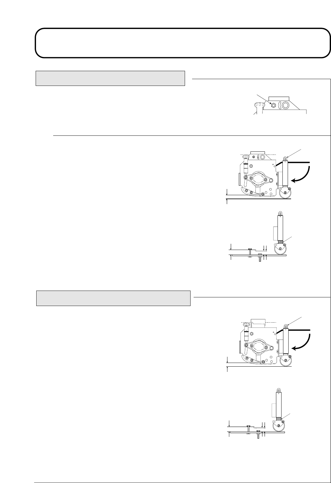
MK3 200mm FIXED CUTTERHEAD
1D876P05A
1D876P08B
B
E
1D876P09A
C
E=
Pivot knuckle fixing: Secure the bolt in the front “fixed” hole
position ‘A’ as shown.
Height of cut adjustment: The height of cut is gauged by the
position of the rear roller.
Turn the adjusting nut assembly ‘B’ both ends clockwise to
decrease height of cut ‘E’ or anti-clockwise to increase height of
cut ‘E’.
IMPORTANT: PREVENT DAMAGE - Do not attempt to
unlock the nut assemblies, ‘B’.
Ensure that all cutterheads are set at the same height of cut by
either referring to the indicator rings ‘C’ or by using a height of
cut gauge across the full width of each cutterhead for greater
accuracy as shown.
MK3 254mm FIXED CUTTERHEAD
Height of cut adjustment: The height of cut is gauged by the
position of the rear roller.
Turn the adjusting nut assembly ‘B’ both ends clockwise to
decrease height of cut ‘E’ or anti-clockwise to increase height of
cut ‘E’.
IMPORTANT: PREVENT DAMAGE - Do not attempt to
unlock the nut assemblies ‘B’.
Ensure that all cutterheads are set at the same height of cut by
either referring to the indicator rings ‘C’ or by using a height of
cut gauge across the full width of each cutterhead for greater
accuracy as shown.
1D876P16A
B
E
1D876P09A
C
E=
A
1.40 1.40
924916KG251004
OPERATING THE MOWER
MK3 200mm FLOATING CUTTERHEAD
1D876P07A
1D876P06B
B
A
D
E
1D876P10A
C
E=
A
F
1.41 1.41
Pivot knuckle fixing: Secure the bolt in the rear “floating” slot posi-
tion ‘A’ as shown.
Height of cut adjustment: The height of cut is gauged by the position
of the front and rear rollers.
To alter the rear roller position, turn the adjusting nut assembly ‘B’ both
ends clockwise to decrease height of cut ‘E’ or anti-clockwise to
increase height of cut ‘E’.
IMPORTANT: PREVENT DAMAGE - Do not attempt to unlock
the nut assemblies, ‘B’.
To alter the front roller position loosen bolts ‘F’. Release and turn
adjusting nuts ‘D’ both ends clockwise to increase the height of cut or
anti-clockwise to decrease the height of cut.
Ensure that all cutterheads are set at the same height of cut by referring
to the indicator rings ‘C’ or use the height of cut gauge across the full
width of each cutterhead as shown.
Tighten nuts ‘D’ and ‘F’ both ends.
CENTRE CUTTERHEAD HEIGHT OF CUT CORRECTION ADJUSTMENT
With all cutterheads set at the same HOC via the indicator rings, it may be noticeable that the centre unit pro-
duces a higher cut finish compared to the wing units. The centre unit is pulled and the wing units are pushed
this presents marginally different cutting angles relative to the ground. The amount of HOC variation, which
results from this will be influenced by the terrain but satisfactory results can usually be achieved by setting the
centre cutterhead HOC indicator ring lower than the wing unit settings.

924916KG251004
OPERATING THE MOWER
MAINTENANCE
WARNING : PREVENT ACCIDENTS - When carrying out maintenance procedures it is essential that:
- The engine is switched off and the ignition key removed.
- The parking brake is applied.
- There is no pressure in the hydraulic system.
- The cutterheads are fully down on the ground.
- The safety precautions in this manual have been read and understood.
IMPORTANT: PREVENT DAMAGE: Regular maintenance is essential for the continued safe
operation of the machine. Correct servicing will prolong the working life of the machine and
safeguard the "Hayter Warranty". Always fit genuine 'Hayter service parts' as these are
accurately matched to the required duty.
Dirt and contamination are the enemies of any hydraulic system. When carrying out maintenance
procedures on the hydraulic system always ensure that the work area and the components are
thoroughly clean before, during and after refitting. Ensure that all open hydraulic lines and ports, etc. are
plugged during maintenance procedures.
The recommended service intervals are based on normal operating conditions. Severe or unusual
conditions will necessitate shorter service intervals.
ALWAYS grease pivot points immediately after pressure washing or steam cleaning, refer - EVERY 50
HOURS, GREASE PIVOT POINTS.
WARNING: PREVENT ACCIDENTS - The engine, transmission oil and hydraulic systems will be
hot after machine use. Allow the systems to cool before working on the machine, particularly
before working on the engine or when changing oil or oil filters.
1.42 1.42

924916KG251004
MAINTENANCE
WARNING : PREVENT ACCIDENTS - Use hazardous substances carefully.
The following fluids are identified as being hazardous;
When using any of the above fluids it is recommended that eye protection and gloves are worn and
that care is taken to prevent spillage.
Avoid contact with skin; wash off spillage with soap and water.
In the case of battery acid drench with water and seek medical attention. Remove any contaminated
clothing and clean thoroughly before use.
Avoid contact with eyes; wash with running water and seek medical attention if symptoms persist.
In the case of battery acid, seek medical attention immediately.
Avoid ingestion; if swallowed seek medical attention.
Keep clear of high pressure fluid escaping from pinholes, cracked connections etc. High pressure
fluid can penetrate the skin. Seek immediate medical advice if any fluid is injected into the skin.
Always use a piece of cardboard or paper when searching for leaks.
CAUTION: PREVENT ENVIRONMENTAL DAMAGE - Dispose of hazardous substances
correctly.
When disposing of hazardous waste products, take them to an authorised disposal site.
Waste products must not be allowed to contaminate surface water, drains or sewerage systems.
CAUTION: PREVENT ENVIRONMENTAL DAMAGE - Dispose of
used battery correctly. The battery has a separate collection mark. This
means that the battery must not be disposed of with general waste. It
must be taken to an authorised disposal site
Assessed risk
Low
Low
Low
Low
Medium
High
Substances
Diesel oil
Lubricating oil
Hydraulic oil
Grease
Anti - freeze
Battery acid
MAINTENANCE Continued.
WS032
1.43 1.43
924916KG251004
MAINTENANCE
ENGINE
Refer to the Engine Operator's Manual for maintenance information.
RUNNING IN PERIOD
Check wheel nut torque settings:
During first 50 hours of use and in addition to routine checks. Refer -
DAILY AND BEFORE USE. Check wheel nut torques twice a day.
Front axle wheel nut torque setting - 200 Nm.
Rear axle wheel nut torque setting - 54 Nm.
RUNNING IN PERIOD - AT FIRST 50 HOURS
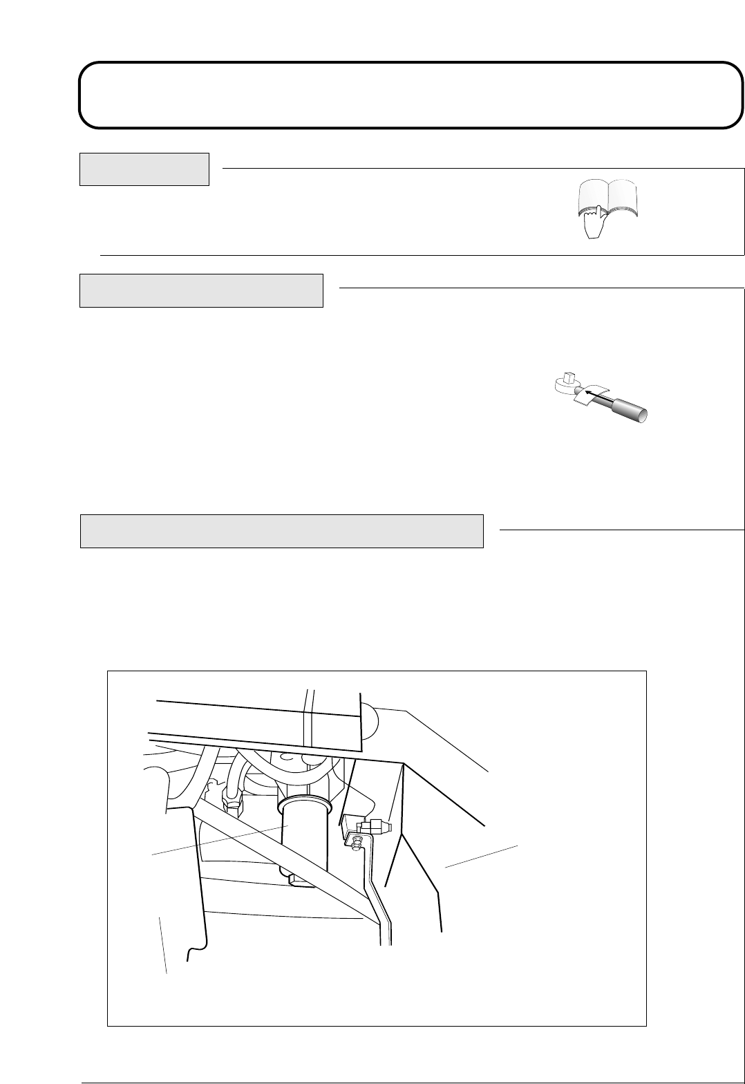
Change the transmission oil filter: Unscrew and remove the bottom of the
transmission oil filter housing. Withdraw the filter element and discard. Refit
a new filter element (Hayter part no. 924709) and replace the housing.
ENGINE
1P953C17
1
2
3
1.44 1.44
1. Transmission oil filter.
2. Centre cutterhead.
3. Hydraulic tank.
924916KG251004
MAINTENANCE
RUNNING IN PERIOD - AT FIRST 50 HOURS
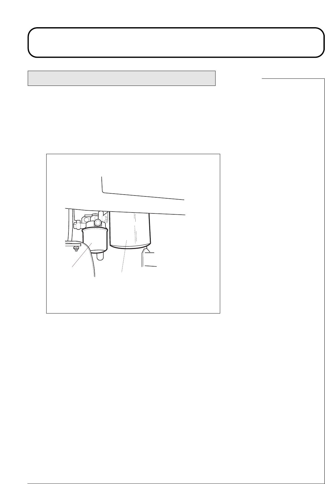
Change the hydraulic oil return filter: Unscrew and remove the
return filter canister and discard. Refit a new filter canister (Hayter
part no. 924692).
1
2
1P953C16A
1. Hydraulic oil return filter.
2. Engine fuel filter.
Continued.
Left Hand Side of Machine
1.45 1.45
924916KG251004
1DT2244A.DRW
MAINTENANCE
1.
2.
3.
1. Air filter
2. Dust bowl.
3. Dust boot.
DAILY AND BEFORE USE
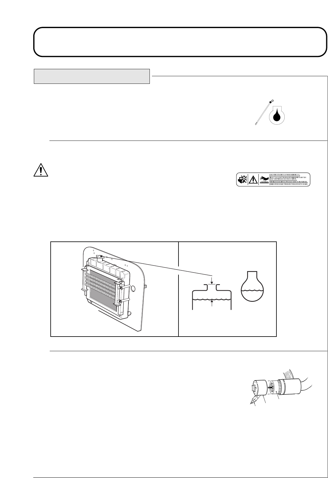
Check engine oil level: If the oil level is below the upper mark on the
dipstick, top up with the correct grade of engine oil to the required level,
refer - ENGINE MANUAL.
Check engine radiator coolant level:
WARNING: PREVENT ACCIDENTS - Avoid scalding. DO NOT
remove the radiator filler cap unless the engine is cool. Turn the filler
cap slowly to release system pressure before removing the filler cap
completely.
The coolant level should be 30 - 40mm below the top of the filler neck.
Top up with the correct coolant mixture, refer - ENGINE MANUAL.
Cleaning the air cleaner: Remove the air filter and tap it repeatedly
with the palm of the hand to remove dust particles. DO NOT damage the
air filter by hitting it against a hard object. Inspect the air filter for signs
of damage.
IMPORTANT: PREVENT DAMAGE - Always replace a damaged
air filter or damage to the engine will result. NEVER run the engine
without the air filter correctly fitted.
Clean the inside of the cleaner dust bowl with a dry cloth and check that
the dust boot is unobstructed.
Replace the air filter and assemble the dust bowl, with the dust boot
facing below horizontal level.
MS016
70-13-073 REV (.0.)
1P924C13A
30 - 40mm
1.46 1.46
924916KG251004
MAINTENANCE
1. Radiator primary screen.
2. Oil cooler
3. Secondary screen
DAILY AND BEFORE USE Continued.
Clean the primary radiator screen: Clean the primary radi-
ator screen. Check the oil cooler, secondary screen and engine
radiator grille for debris and clean as necessary using a brush
or airline. The secondary screen can be removed for cleaning.
Re-assemble the secondary screen. If water is used, these
areas should be allowed to dry out completely before use.
IMPORTANT: PREVENT DAMAGE - NEVER operate
the mower with a damaged radiator screen or engine
damage could result from overheating. Clean the radiator
screen more regularly in dry conditions.
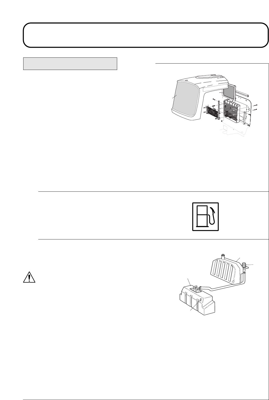
Check fuel level: Top up as necessary with diesel fuel.
Always top up before storing the mower over-night to prevent
water condensation from contaminating the fuel.
Check hydraulic oil level: If the oil level is below the upper
mark on the sight level gauge, top up with the correct grade
of hydraulic oil as necessary, refer- SPECIFICATIONS.
WARNING : PREVENT DAMAGE - If there is
noticeable hydraulic oil loss, the leakage source must be
rectified before using the mower. NEVER operate the
mower when the hydraulic oil level is below the bottom
mark on the sight level gauge. NEVER operate the
mower with contaminated oil.
3
4
1
1D924P06A
2
D
1. Sight level gauge
2. Oil tank
3. Oil filler cap.
4. Fuel tank.
1P924C09
A
1
2
3
1.47 1.47
924916KG251004
MAINTENANCE
DAILY AND BEFORE USE Continued.
Check hydraulic hose-lines: Inspect hydraulic hose-lines for signs of wear or damage.
WARNING: PREVENT ACCIDENTS - ALWAYS replace worn or damaged hydraulic hose-lines
immediately. DO NOT operate the mower with defective hydraulic hose-lines.
Inspect the mower for signs of oil leakage. Tighten fittings or replace seals as required.
Check fasteners: Check that all nuts, bolts and pins are secured correctly
in place and in good condition.
Check safety devices:
WARNING - PREVENT ACCIDENTS : Ensure that all safety guards,
shields and protective devices are securely in place and in good working
order.
Check tyres: Examine the condition of the tyres and check that inflation
pressures are correctly set, refer - SPECIFICATIONS.
WARNING - PREVENT ACCIDENTS : Ensure that damaged tyres
are replaced. Ensure that tyre tread depths comply with road traffic
regulations.
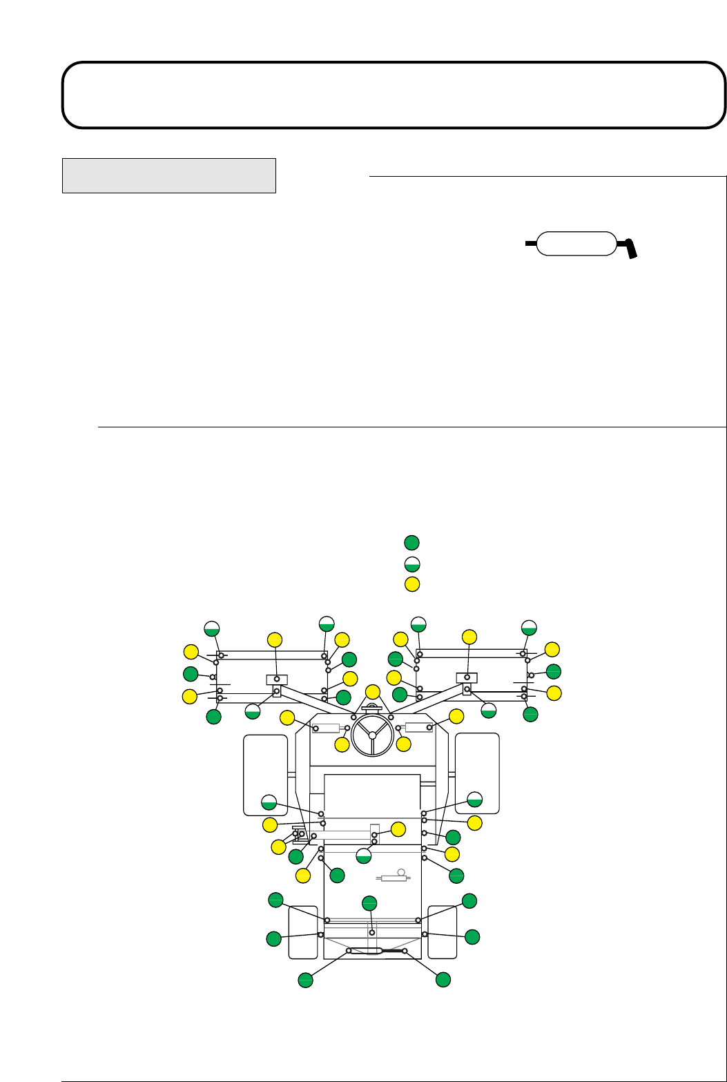
Grease all rear axle components including the centre axle beam pivot pin,
both steering yokes, track rod ball joints and steering cylinder ball joints,
refer - EVERY 50 HOURS, GREASE PIVOT POINTS.
Check cutterheads: Examine the condition of the cutting cylinders and bottom blades. Adjust as
necessary, refer - CUTTERHEAD CYLINDER TO BOTTOM BLADE ADJUSTMENT.
Grease all cutterhead rollers with a good quality medium grade grease and ensure that sufficient grease
is injected such that clean grease is seen to escape from the roller end cap, refer - EVERY 50 HOURS.
If no grease can be seen escaping from the roller end cap it can be assumed that the rear seal has failed,
resulting in the the roller shell being filled with grease.
Note: Care should be taken if an industrial power greaser is used as this may result in damage to
the bearing sealing arrangement.
Check forward/reverse travel pedal action: With the engine switched ‘off’, operate the forward and
reverse travel pedals through the full range of articulation and ensure that the mechanism returns freely
to the neutral position.
WARNING - PREVENT ACCIDENTS: Do not operate the machine if there are any signs of
‘Stickiness’ in the pedal mechanism which prevents a free return to the neutral condition.
1.48 1.48

924916KG251004
MAINTENANCE
Check operator presence controls:
WARNING : PREVENT ACCIDENTS -Keep bystanders away when checking operator
presence control interlock switches. DO NOT use the mower unless the operator presence con-
trols work correctly as described below. If difficulties arise, consult your "Hayter dealer”.
Operator presence seat switch: Sit on the operator seat and start the engine. Lower the cutterheads
to the ground and engage the cutter drive in the forward direction. Rise from the operators seat and
check that the cutting cylinders come to a stop after an initial 0.5 to 1 second delay. Repeat with the
cutting cylinders running in reverse.
Cutter drive interlock switch: Stop the mower engine. Operate the cutter drive switch to the ‘off’
position and turn the ignition key to position ‘I’. The cutterhead drive switch indicator light should illu-
minate. Refer - OPERATING THE MOWER.
Operate the switch to the ‘forward’ position. The indicator light should go out and the engine should
not start when the ignition key is turned. Repeat for the ‘reverse’ position.
Parking brake interlock switch: Stop the engine. Engage the parking brake and turn the ignition key
to position ‘I’. The parking brake indicator light should illuminate. Refer - OPERATING THE
MOWER.
Disengage the parking brake. The indicator light should go out and the engine should not start when
the ignition key is turned.
Sit on the operator seat and start the engine. Release the parking brake. Rise from the operator seat and
check that the engine stops.
Transmission neutral interlock switch: Stop the mower engine and remove the foot from the for-
ward/reverse travel pedals. Turn the ignition key to position 'I’ and the transmission neutral indicator
light should illuminate. Application of light pedal pressure in a forward and reverse direction should
cause the indicator light to go out. Take extreme care to ensure that the area around the mower is clear
before checking that the engine will not start under this condition.
1.49 1.49
DAILY AND BEFORE USE Continued.
924916KG251004
MAINTENANCE
EVERY 50 HOURS
Perform routine checks : Refer - DAILY BEFORE USE.
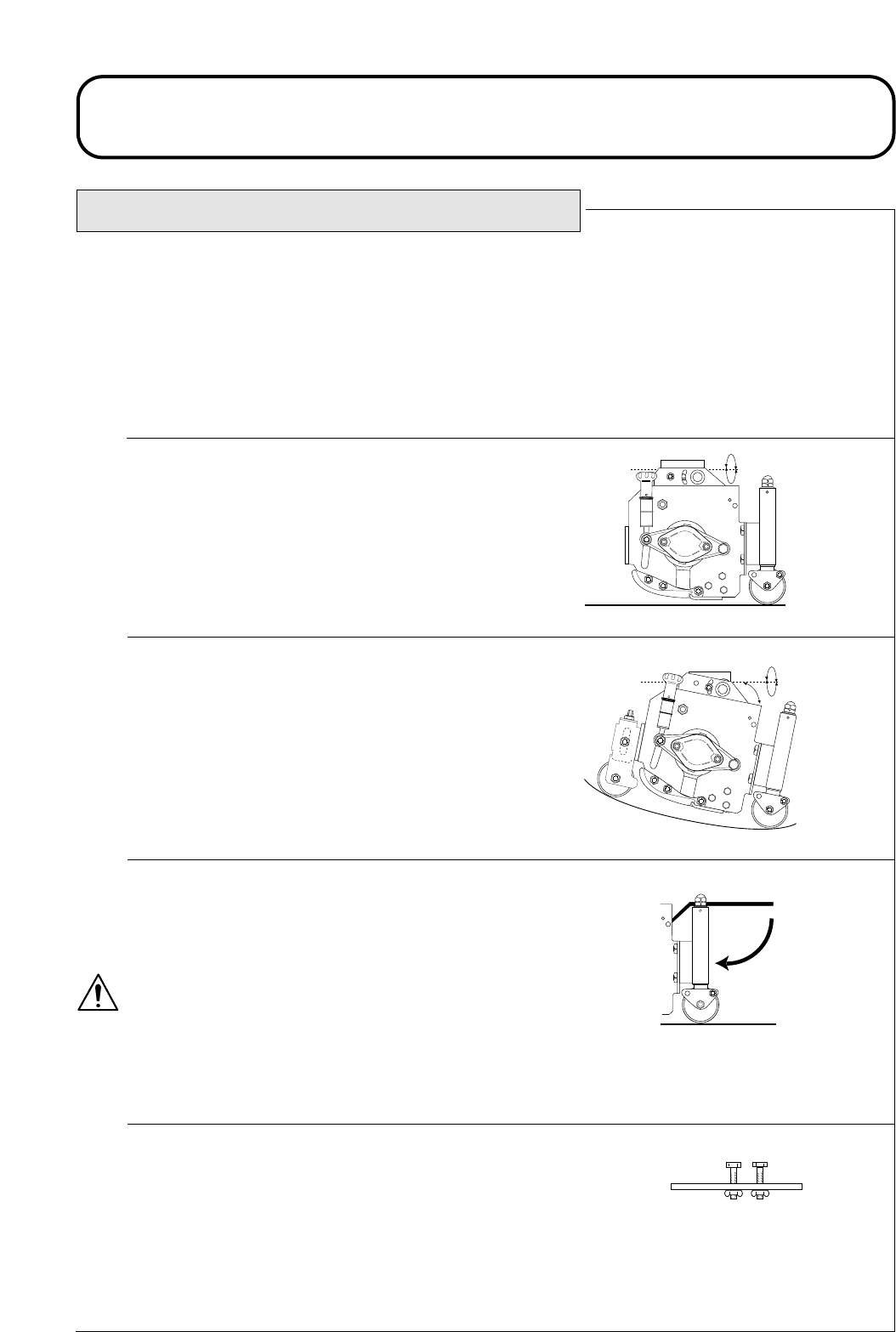
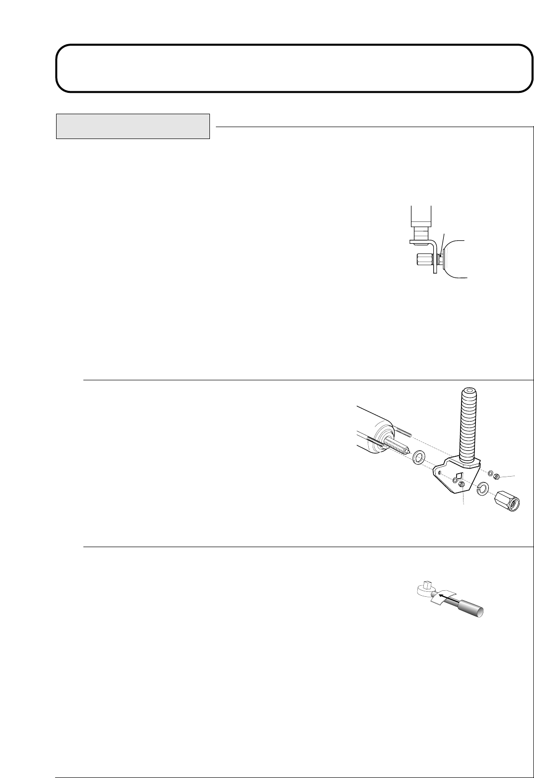
Check cutterhead roller bearing adjustment:
Important: Prevent Damage - It is essential that the cutter-
head roller bearings are kept in good adjustment in order to
ensure maximum working life. If roller end float is allowed
to become excessive premature bearing failure will result.
Grip the roller and move from side to side and up and
down. If excessive movement is detected proceed as follows:
Carefully tighten nuts ‘A’ at each end of the roller with the
spanner provided, just sufficiently to remove any end float.
Note: The roller should still rotate freely after adjustment.
Overtightening of nuts ‘A’ could lead to premature bearing
failure.
Check cutterhead rear roller scraper wire tension:
It is important that the scraper wires are correctly tensioned so
as to ensure correct operation and maximum working life.
Carefully tighten the scraper wire retaining nuts ‘B’ so as to just
remove any slack from the scraper wires then tighten nuts ‘B’ a
further four full turns to correctly tension the wire.
IMPORTANT: PREVENT DAMAGE - Do not over tighten
the scraper wires.
Check wheel nut torque settings:
Front axle wheel nut torque setting - 200Nm.
Rear axle wheel nut torque setting - 54 Nm.
1.50 1.50
A
3D924S001A
B
B
924916KG251004
MAINTENANCE
EVERY 50 HOURS Continued.
Grease pivot points : Clean and grease all grease points with a
good quality compound of the grade specified, refer -
SPECIFICATIONS.
Replace any grease nipples which are damaged.
Grease all cutterhead grease points and ensure that sufficient
grease is injected such that clean grease is seen to escape from
the roller end caps. This provides visible evidence that the roller
seals have been purged of grass debris etc. and will ensure
maximum working life.
1.51 1.51
DAILY
DAILY (IF FITTED)
50 HOUR (WEEKLY)
GREASE POINTS
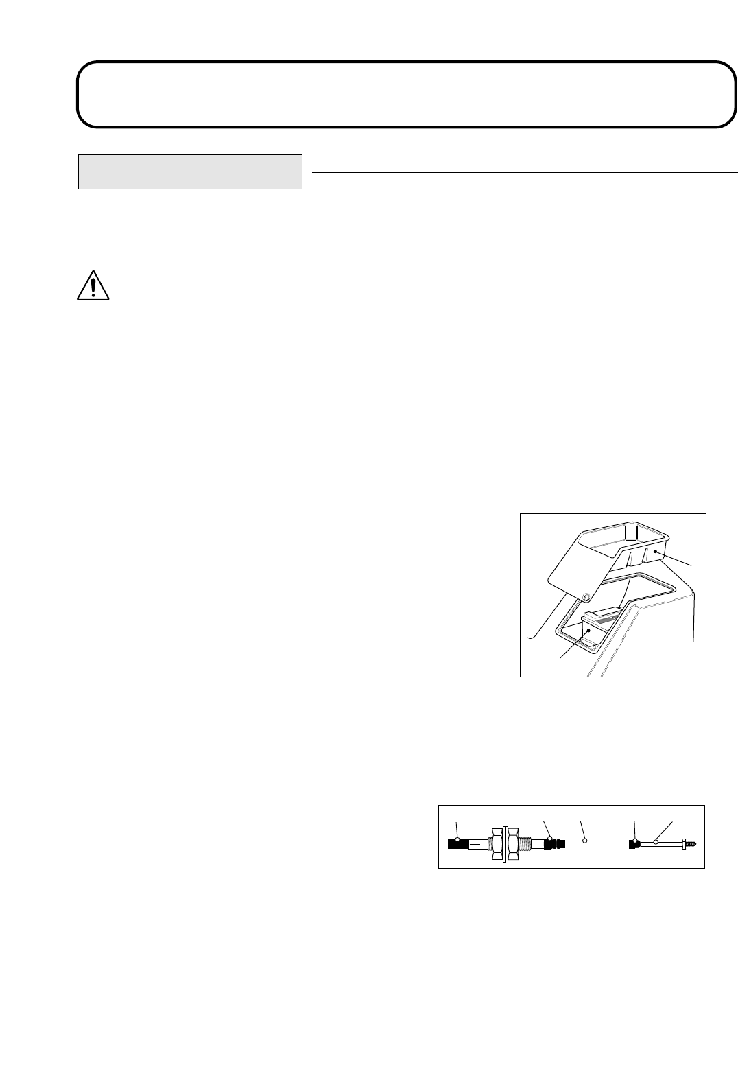
924916KG251004
MAINTENANCE
EVERY 250 HOURS
Perform routine checks : Refer - DAILY BEFORE USE.
- EVERY 50 HOURS.
Check battery condition :
WARNING : PREVENT ACCIDENTS - Explosive gases are produced by the battery. Work in a well
ventilated area, away from all sources of ignition.
Battery fluids are corrosive. Take care to avoid contact with the skin or eyes. In the event of a spillage,
drench the affected area with water. If the eyes are affected, seek medical attention. Remove any cont-
aminated clothing and clean thoroughly before use.
When removing the battery, always disconnect the negative (-) cable first.
When replacing the battery, always connect the negative (-) cable last.
Remove the tool tray to gain access to the battery. Remove any corrosion from the battery terminals using a wire
brush and apply petroleum jelly to the terminals to prevent further corrosion. Clean the battery compartment.
Under normal operating conditions the battery will not require any further
attention. If the machine has been subject to continuous use under high
ambient temperature conditions, the battery electrolyte may require topping
up. Remove the cell covers and top up with distilled water to a height 15mm
below the top of the battery. Replace the cell covers.
IMPORTANT : PREVENT DAMAGE - Check the condition of the
battery cables. Replace cables showing signs of wear or damage and
tighten any loose connections as necessary.
Visually inspect transmission control cable and operating mechanism:
Check the condition and security of the cable and operating mechanism at the speed control pedal and trans-
mission pump ends.
- Remove build up of dirt, grit and other deposits.
- Ensure that the ball joints are securely anchored and
check that mounting brackets and cable anchors are
tight and free from cracks.
- Inspect end fittings for wear, corrosion, broken springs
and replace if necessary.
- Ensure that the rubber seals are correctly located and in good condition.
- Ensure that the articulating sleeves supporting the inner cable are in good condition and firmly attached to
the outer cable assembly at the crimped connections. If there are any signs of cracking or detachment fit
new cable immediately.
- Check that sleeves, rods and inner cable are free from bends, kinks and other damage. If there are any signs
of such failure, fit a new cable immediately.
- Check the condition of the neutralising device and replace if worn.
- With the engine switched ‘Off’, operate the pedal controls through the entire range and ensure that the
mechanism moves smoothly and freely to the neutral position without ‘Sticking’ or ‘Hanging up’.
1
2
1D924P14A
1. Battery
2. Tool Tray
1.52 1.52
Outer Cover Sleeve Rod EndRubber Seal Rubber Seal
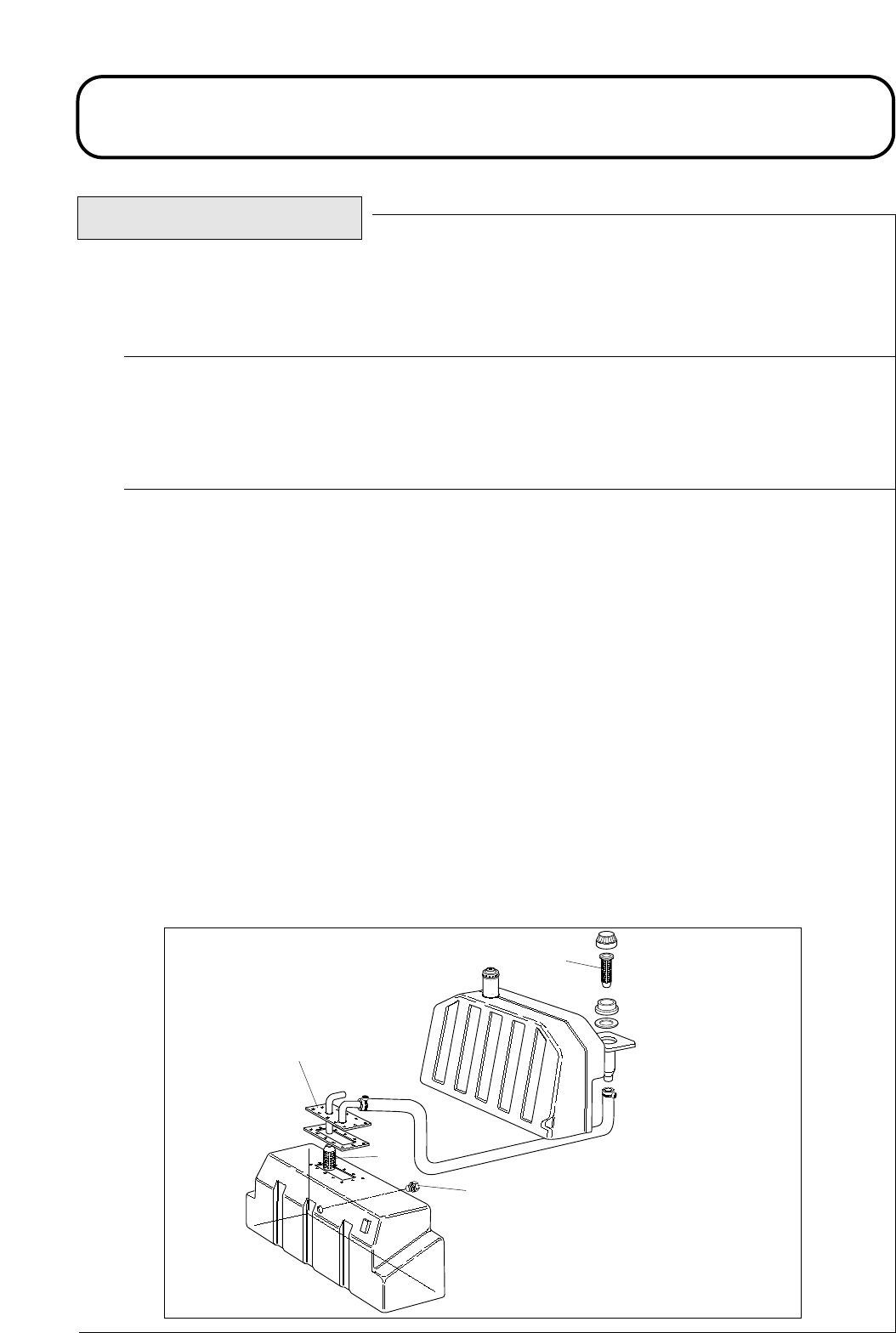
924916KG251004
MAINTENANCE
Perform routine checks : refer
Thoroughly clean the machine:
IMPORTANT: PREVENT DAMAGE - Keep water away from electrical components. Use a dry
cloth or brush to clean such areas.
Service the hydraulic system : This procedure is best carried out when the hydraulic oil is warm (not
hot). Lower the cutterheads to the ground and drain the hydraulic system by removing the hydraulic tank
drain plug. Remove the oil tank filler flange to gain access to the suction strainer. Unscrew and remove
the strainer and clean with paraffin or petrol before replacing. Renew the strainer if there are any signs
of damage.
Remove the oil filler cap strainer and clean before replacing. Renew the strainer if there are any signs
of damage.
Renew the return line oil filter element, refer - RUNNING IN PERIOD AT FIRST 50 HOURS.
Renew the transmission oil filter element, refer - RUNNING IN PERIOD AT FIRST 50 HOURS.
Replace the drain plug and refill the hydraulic tank with fresh clean hydraulic oil of the recommended
grade, refer - SPECIFICATIONS.
Run the machine and operate all hydraulic systems until the hydraulic oil is warm. Recheck the oil level
and top up as necessary to the upper mark on the sight level gauge.
EVERY 500 HOURS
- DAILY BEFORE USE.
- EVERY 50 HOURS.
- EVERY 250 HOURS.
3
4
1
1D924P05B
2
1. Drain plug
2. Oil tank filler flange
3. Suction strainer
4. Filler strainer
1.53 1.53
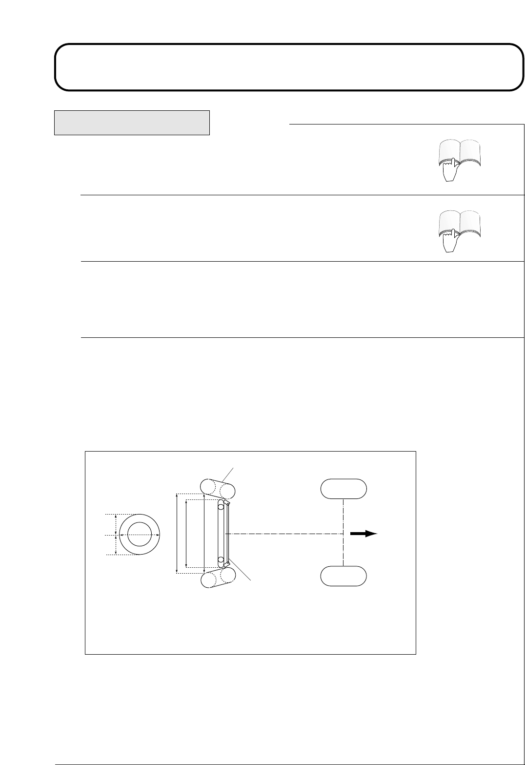
924916KG251004
MAINTENANCE
3D3122A
x + 3 - 8mm
x
4
3
2
1
1. Wheel centre height
2. Tyre
3. Direction of forward travel
4. Track-rod assembly
1.54 1.54
Continued.
ENGINE
ENGINE
EVERY 500 HOURS
Renew the engine air cleaner filter: Check the condition of the air cleaner
hoses. Replace any hose which is damaged and tighten the connections, refer -
ENGINE MANUAL.
Renew the engine fuel filter element: Refer - ENGINE MANUAL.
Check electrical system: Inspect all electrical connections and cables and replace any which are damaged
or corroded. Spray a good quality water inhibitor onto exposed connections to prevent moisture ingress.
Check rear wheel alignment: To prevent excessive tyre wear and ensure safe machine operation, the rear
wheels must be correctly aligned to ‘toe - in’ by 3 - 8mm.
Set the rear wheels in the straight ahead position. Measure and compare the distance between the front
sidewalls and the rear sidewalls at the wheel centre height. The distance between the front sidewalls must
be set 3 - 8mm less than the distance between the rear sidewalls.
To adjust the alignment of the rear wheels, first back off the left hand and right hand locknuts on the track
rod assembly. (Left hand locknut is a left hand thread). Rotate the track rod to achieve the correct
‘toe - in’ as described above and tighten the locknuts securely.
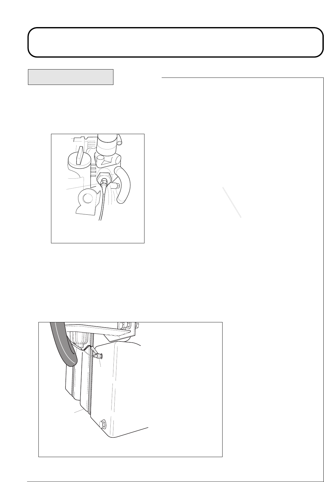
924916KG251004
MAINTENANCE
1P953C15A
1
2
1.
1. Temperature Switch
2. Hydraulic oil tank
EVERY 500 HOURS Continued.
Check the engine overheat warning system: Turn the ignition key to the ‘ignition on’ position 'I'.
Disconnect the red/grey wire terminal from the engine temperature switch and touch the metal terminal of
this wire onto a suitable earth point, ensuring that the metal surfaces make good contact. The horn will
sound and the engine coolant temperature warning light will illuminate to confirm correct operation. If the
system is faulty, make repairs before operating the mower.
Check the hydraulic oil overheat warning system: Turn the ignition key to the ‘ignition on’ position 'I'.
Disconnect the red/blue wire terminal from the hydraulic tank temperature switch and touch the metal
terminal of the wire onto a suitable earth point, ensuring that the metal surfaces make good contact. The
horn will sound and the hydraulic oil temperature warning light will illuminate to confirm correct
operation. If the system is faulty, make repairs before operating the mower.
1.55 1.55
1
1P953C01A
1. Temperature switch.
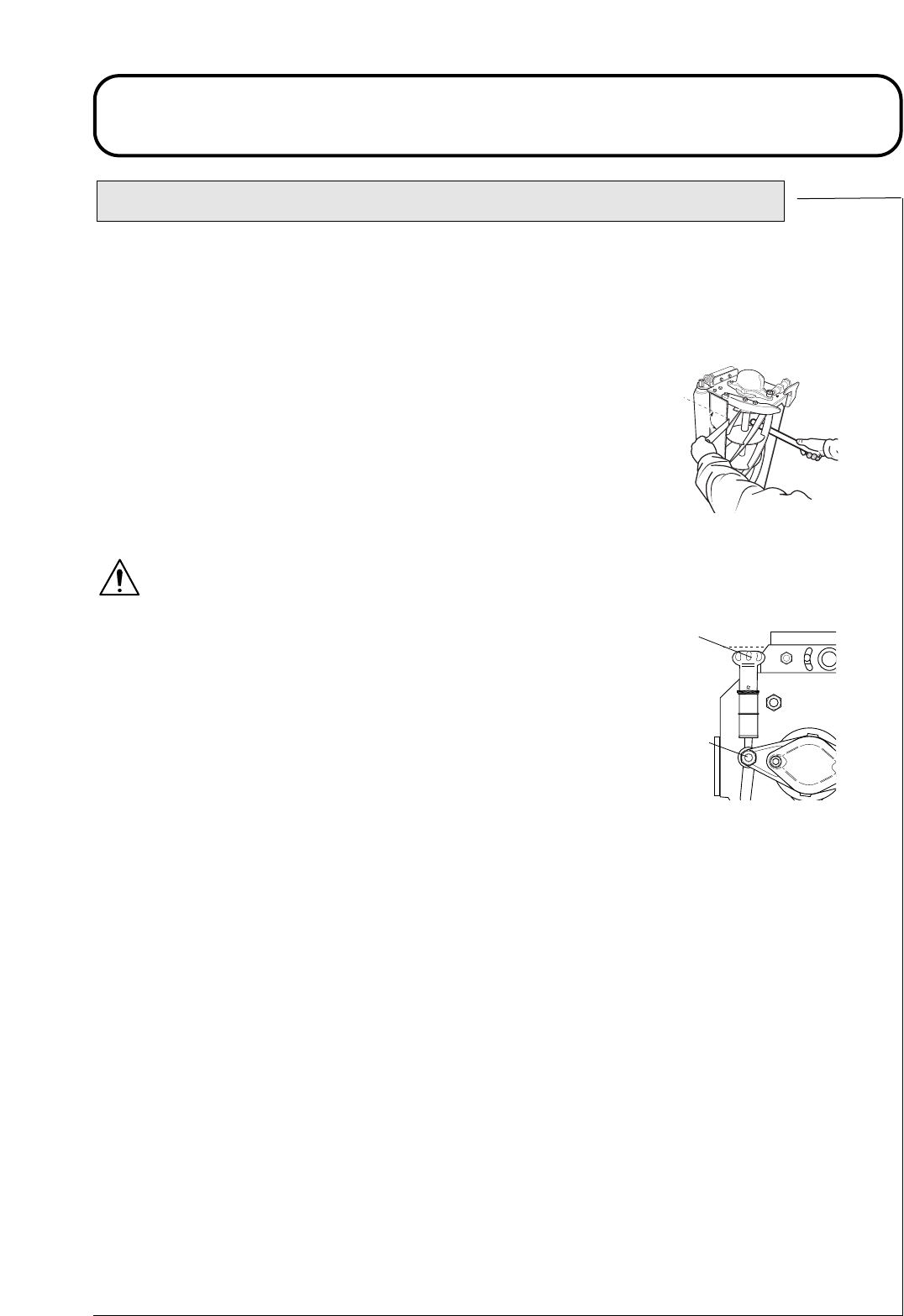
CUTTERHEAD CYLINDER TO BOTTOM BLADE ADJUSTMENT
IMPORTANT : PREVENT DAMAGE - It is essential that the
relationship between the bottom blades and the cutting cylinders is
kept in good adjustment in order to ensure good cutting performance,
minimum power consumption and prolonged life for the cutting edges.
Carry out the following procedure before commencing work and re-check
the settings every few hours.
Check that the cutting cylinder is correctly set to the bottom blade by
holding a thin piece of paper between the cutting cylinder and the bottom
blade as shown. Carefully rotate the cylinder as shown and check that the
paper is cut cleanly at all points along the length of the blade. Hold the
paper at 90 degrees (right angles) to the bottom blade to obtain the correct
cutting action.
WARNING: PREVENT ACCIDENTS - Ensure that people are clear
of the cutting cylinders as rotation of one may cause others to rotate.
If adjustment is necessary proceed as follows;
Release nut 'A' 1/4 turn both ends.
Turn handwheel 'B' each end alternately whilst rotating the cutting
cylinder backwards until the bottom blade is in 'fleeting' contact with the
cylinder along its entire length. Re-check the cutting action along the
length of the bottom blade using a thin piece of paper making marginal
adjustments as necessary.
Tighten nut 'A' both ends.
If it is impossible to obtain a good clean paper cut across the entire length of the bottom blade it will
be necessary to carry out the backlapping procedure to reprocess the cutting edges. In severe cases it
will be necessary to regrind the cutting cylinder and the bottom blade, refer - BACKLAPPING /
GRINDING.
Do not be tempted to over adjust, thus causing heavy contact between the cylinder and bottom blade,
as this will cause very rapid uneven wear to take place leading to tramlining and waviness of the cut-
ting edges. The frictional losses will be high and a significant amount of power will be absorbed, thus
reducing the power available for cutting. The heating effect due to friction will cause excessive expan-
sion to take place which will further aggravate the situation by increasing the contact pressure.
If the cutterheads are allowed to operate for more than a few hours without adjustment the running wear
will eventually cause the cylinder to run out of contact with the bottom blade. At this stage very rapid
rounding of the cutting edges will occur as grass and abrasive particles pass through the
clearance between the blades.
Lack of attention to adjustment can therefore be foolhardy as maintenance costs will escalate. The qual-
ity of cut will also be seriously affected as will the health and growth of the grass.
An experienced operator will notice when a cutterhead starts to go out of adjustment; when the grass
ceases to be cut cleanly and the cut ends become ragged.
924916KG251004
MAINTENANCE
90
0
B
A
1.56 1.56
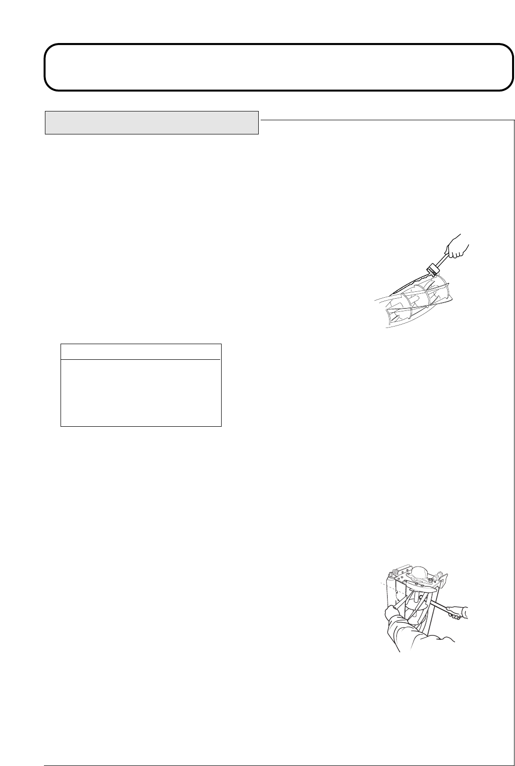
924916KG251004
MAINTENANCE
CUTTERHEAD BACKLAPPING
This process is recommended for restoring the sharp cutting edges to
cylinders and bottom blades which are essential for good quality grass
cutting.
This process can only deal with a small amount of metal removal to restore
the cutting edges. If the blade edges are seriously worn or damaged it will
be necessary to remove the component parts and have them reground.
The backlapping process:
Check that the mower engine is switched off and the parking brake applied.
Adjust the cutting cylinders to the bottom blades to obtain ‘fleeting contact’.
Apply a medium grade detergent based carborundum paste to the cutting
edges of the cylinders with a long handled brush.
Ensure that the area surrounding the cutterheads is clear of people and keep
hands and feet clear of the cutting cylinders during the period when the
mower engine is running.
Sit on the operator seat, start the mower engine and set the engine speed at
idle.
Operate the cutterhead drive switch to the 'reverse/backlap' position for a
period of time and listen to the grinding action .
Operate the cutterhead drive switch to the 'off' position and switch off the
mower engine when the grinding action has stopped.
Thoroughly clean the blade edges and adjust the cutting cylinders to the
bottom blades. Check that a thin piece of paper can be cut cleanly at all
points along the cutting edges while rotating the cylinders by hand.
If further backlapping is necessary repeat steps 2 to 8.
Thoroughly remove and wash off all traces of the carborundum paste from
the cylinders and bottom blades.
1.
2.
3.
4.
5.
6.
7.
8.
9.
10.
80 Grade Carborundum paste
0,45 kg
11,25 kg
Hayter Part No:
63-07-088
63-07-086
900
1.57 1.57

924916KG251004
MAINTENANCE
CUTTERHEAD GRINDING
It will be necessary to carry out a grinding operation to correct cylinder spiral edges or bottom blade
edges which have become excessively rounded or distorted. Bottom blades which are nearing the end
of their wear life should be replaced. The new blades should be ground on their holders prior to fitting,
refer - CUTTERHEAD BOTTOM BLADE REPLACEMENT. When grinding operations are necessary
it is essential that both cylinders and bottom blades are ground at the same time. The only exception to
this rule is when a new cylinder is fitted in which case it is only necessary to grind the bottom blade.
All such grinding operations should be carried out by your dealer on a quality, well maintained
cylinder/ bottom blade grinding machine.
CUTTERHEAD BOTTOM BLADE REPLACEMENT
Remove the bottom blade holder by removing the three fixing bolts at each end and withdraw from the
cutterhead. Remove the worn bottom blade and discard the countersunk screws and securing nuts. Fit
the new blade to the holder and loosely assemble with new countersunk screws and securing nuts.
Tighten the centre bolts to a torque of 40 Nm. Continue by tightening the remaining bolts to the same
torque by working from the centre out towards the blade ends.
The new bottom blade must be ground on its holder prior to refitting to the cutterhead.
Adjust the cutting cylinder position to give adequate clearance for fitting the new bottom blade holder.
Refit the bottom blade holder assembly to the cutterhead using the original fixing bolts and tighten to
a torque of 35 Nm. Finally adjust the cylinder to the bottom blade, refer - CUTTERHEAD CYLINDER
TO BOTTOM BLADE ADJUSTMENT.
1.58 1.58
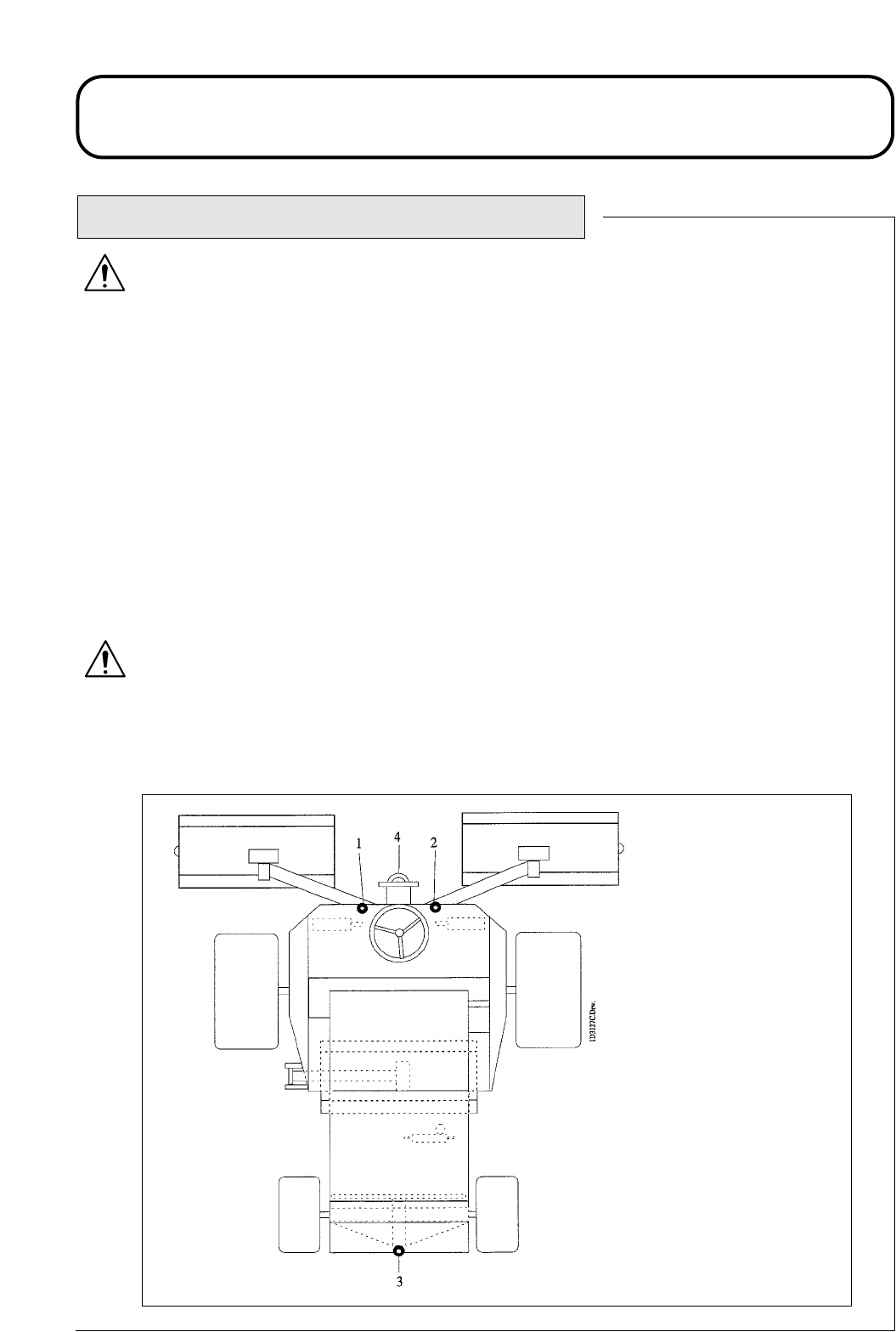
924916KG251004
MAINTENANCE
-
-
-
-
-
-
-
-
-
RAISING THE MOWER OFF THE GROUND
WARNING: PREVENT ACCIDENTS - Before raising the mower ensure that:
The lifting device to be used is in good condition and capable of supporting the weight of the
mower securely. Minimum lift capacity 2000 Kg.
The mower is on level ground.
The parking brake is applied.
The engine is switched off and the ignition key removed.
The ground under the lifting device is level and firm.
The lifting device is secure against one of the mowers lifting points.
If raising the front of the mower, both of the rear wheels must be chocked securely to prevent the
mower rolling away. Note that the parking brake only operates on the front wheels.
WARNING: PREVENT ACCIDENTS - When the mower is raised off the ground:
NEVER crawl under the mower.
NEVER start the engine.
1. Front left hand lifting point
2. Front right hand lifting point
3. Rear towing eye and lifting point
4. Front towing eye
1.59 1.59
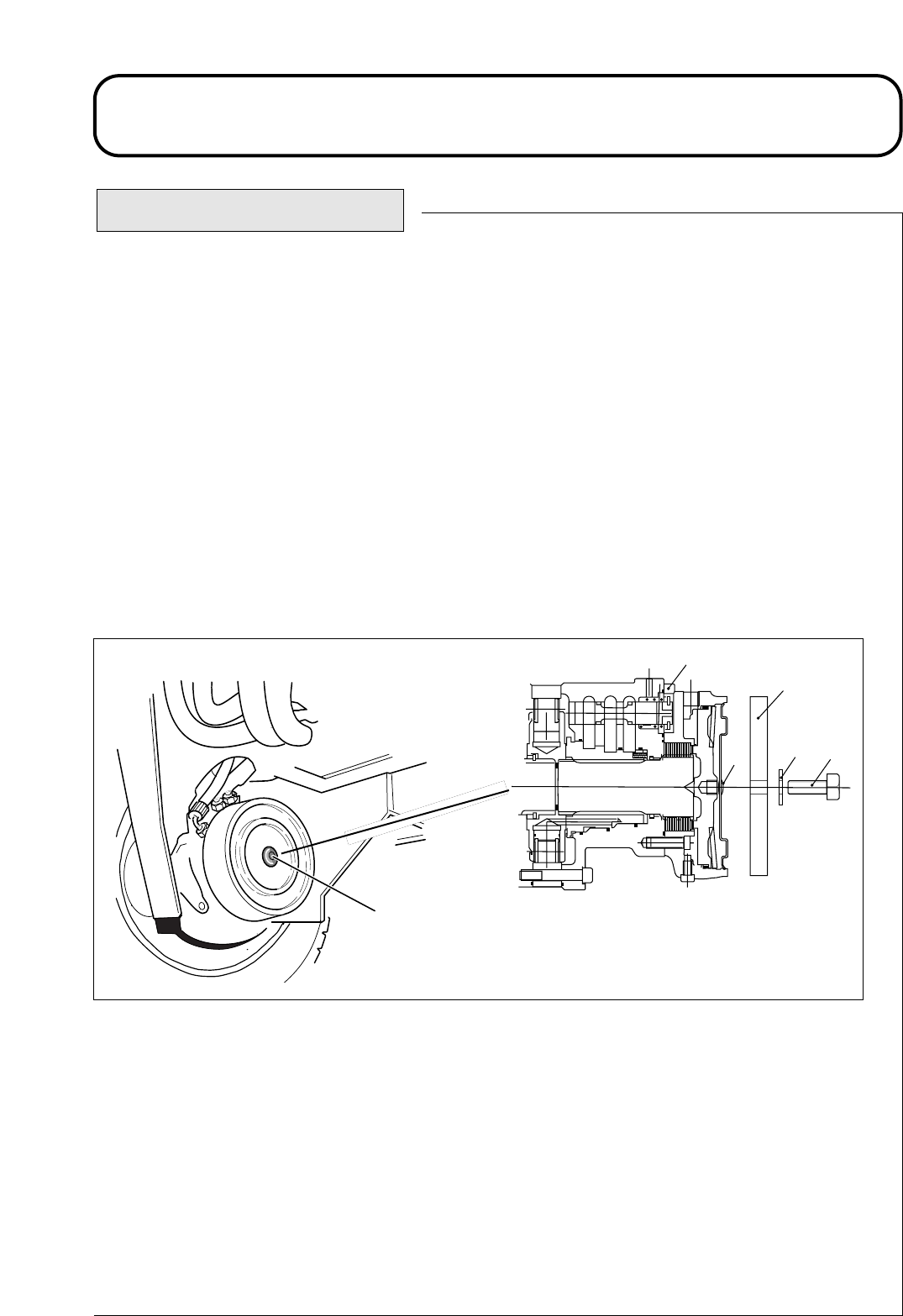
924916KG251004
MAINTENANCE
TOWING THE MOWER
Towing procedure : Connect a rigid tow bar between the towing eye on the mower and a suitable
towing vehicle. Ensure that the towing vehicle specification is suited to braking the combined vehicle
weight to rest whilst effecting complete control at all times. Ensure the towing vehicle’s parking brake
is applied. Chock the mower front wheels to prevent the mower rolling away.
De-commission the front wheel motor disc brakes as follows :-
i) Identify the right hand front wheel motor disc brake assembly and remove the rubber plug (item 2).
Position a M12 x 40mm long setscrew (item 5) with washer (item 4) through the brake release bar (item
3) and into the hole in the centre of the motor end plate. Tighten the setscrew (item 5) into the
threaded hole in the brake piston until the brake is released.
ii) Identify the left hand front wheel motor disc brake assembly and repeat the previous procedure.
1.60 1.60
1
2
1D950R01
3
45
1D950R02
2
1. Front wheel motor - (950620).
2. Rubber Plug - (950639).
3. Brake Release Bar - (950348).
4. Washer - M12 - (09485).
5. Setscrew M12 x 40 - (ZDH1L040U).
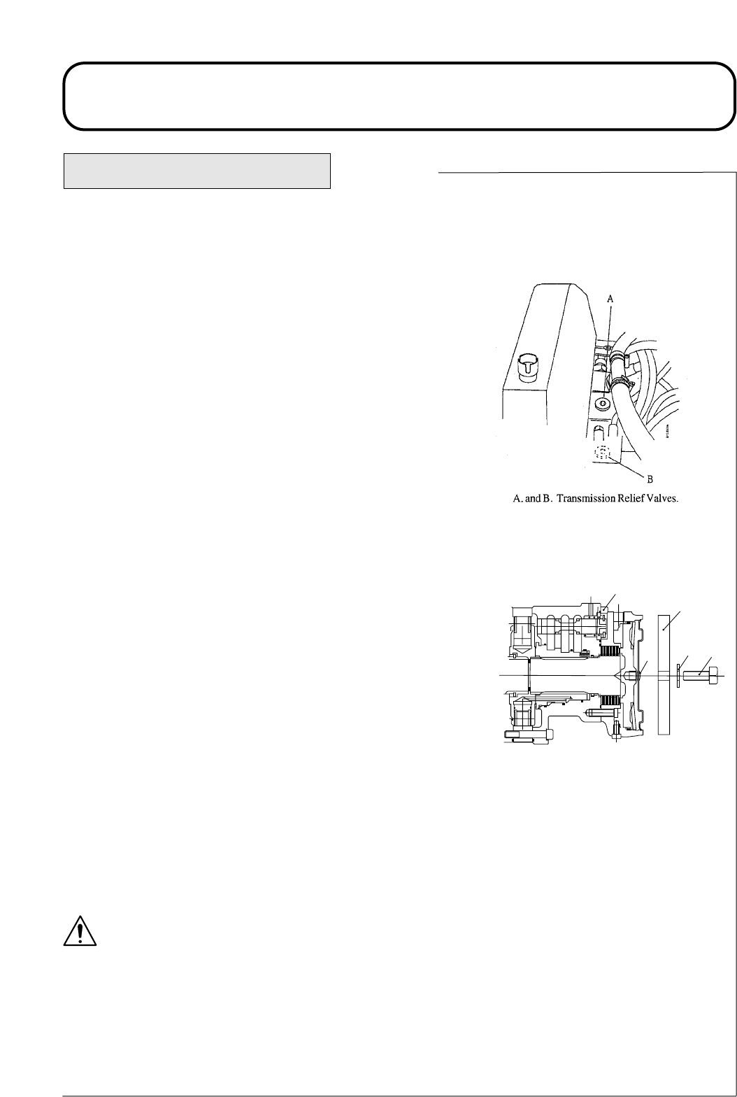
924916KG251004
MAINTENANCE
De-commission the hydraulic service braking system as follows:-
i) Open the 2 transmission relief valves A and B situated on the
transmission pump. The valves are fully open at 2 anticlockwise
revolutions. Do not open the valves past 2 revolutions.
The steering must be operated manually when the mower is being
towed. The steering will feel heavy as there is no hydraulic
assistance when the engine is switched off.
The mower is now in a free wheel condition and can be towed for
a short distance at slow speed. Remove wheel chocks before
towing.
After towing the mower: To return the mower to its normal work-
ing condition the following procedure must be adopted.
Chock the front wheels and re-commission the hydraulic service
braking system as follows :-
i) Close the 2 transmission relief valves. Turn clockwise and
tighten to a torque of 41- 68 Nm.
Re-commission the front wheel motor disc brakes as follows :-
i) Identify the right hand front wheel motor disc brake assembly.
Rotate the setscrew (item 5) anti-clockwise and remove together
with Washer (item 4) and brake release bar (item 3). Reassemble the
rubber plug (item 2) into the motor end plate.
ii) Identify the left hand front wheel motor disc brake assembly and
repeat the previous procedure.
Store the brake release bars, washers and setscrews (items 3, 4 and
5) for future use.
Remove the wheel chocks.
Disconnect the tow bar.
The mower braking system will now operate in the normal way.
WARNING: PREVENT ACCIDENTS - Before using the
mower, ensure that the braking system operates correctly.
Carry out initial checks with the mower at slow speed. Do not
operate the mower with a defective braking system. Do not
operate the mower with the brakes de-commissioned.
TOWING THE MOWER Continued.
1. Front wheel motor - (950620).
2. Rubber Plug - (950639).
3. Brake Release Bar - (950348).
4. Washer - M12 - (09485).
5. Setscrew M12 x 40 - (ZDH1L040U).
1
2
1D950R01
3
45
1.61 1.61

924916KG251004
GRASS CUTTING FAULTS
Turning too tightly.
Mower sliding sideways when travel-
ling across face of a slope.
One end of cutterhead out of ground
contact caused by:
- Poorly routed hoses or wrongly
positioned hydraulic adaptors.
- Pivot pins seizing.
- Grass build up under cutterhead.
Forward speed too high.
Cylinder speed too slow.
Height of cut too low.
Cylinder is running slow.
Inconsistent height of cut setting on one
cylinder.
Raise/Lower position control not in
float position.
One end of cutterhead out of ground
contact caused by:
- Poorly routed hoses or wrongly
positioned hydraulic adaptors.
- Pivot pins seizing.
- Grass build up under cutterhead.
GRASS CUTTING FAULTS
Areas of uncut grass at
point of overlap between
cutting cylinders.
Ridge lines in the cut
across the direction of
travel over full width.
Ridge lines in the cut
grass across the direc-
tion of travel over the
cutting width of one
cylinder.
Step in cut grass height
at point of overlap
between cutting cylin-
ders.
Reduce turning radius.
Mow up/down slope.
Reroute hoses/reposition
hydraulic adaptors.
Free off and grease pivot pins.
Remove grass.
Reduce forward speed.
Increase mower engine speed.
Raise height of cut.
Refer - TROUBLE SHOOTING
for remedy.
Check and readjust height of
cut setting.
Operate position control
to float position.
Reroute hoses/reposition
hydraulic adaptors.
Free off and grease pivot
pins.
Remove grass.
FAULT POSSIBLE CAUSE REMEDY
1.62 1.62

924916KG251004
GRASS CUTTING FAULTS
GRASS CUTTING FAULTS Continued.
Scalping.
Lines of uncut or badly
cut grass in direction of
travel.
Tramlining of cutting edges due to
heavy contact caused by poor cutting
cylinder to bottom blade adjustment.
Bottom blade in ground contact.
Nose down attitude of bottom blade.
Cutterheads bouncing.
Worn cylinder bearings/bearing housing
pivots.
Loose components in cutterhead.
Undulations too severe for height of cut
setting.
Height of cut too low.
FAULT POSSIBLE CAUSE REMEDY
Backlap or regrind to restore
cutting edges.
Raise height of cut.
Readjust cutterhead to ensure
bottom blade is parallel to
ground.
Reduce forward speed.
Reduce weight transfer.
Replace worn parts.
Check and retighten as necessary.
Use floating cutterheads.
Raise height of cut.
Cutting cylinder is partially out of contact
with the bottom blade.
Cutting cylinder is in heavy contact with
the bottom blade.
Height of cut is too high.
Cutting edges of cutting cylinders/bottom
blades are rounded.
Readjust cutting cylinder to
bottom blade.
Readjust cutting cylinder to the
bottom blade.
Lower height of cut setting.
Backlap or regrind to restore
cutting edges.
Some uncut or poorly
cut strands of grass..
1.63 1.63

924916KG251004
GRASS CUTTING FAULTS
FAULT POSSIBLE CAUSE REMEDY
GRASS CUTTING FAULTS Continued.
Excessive bottom blade
wear..
Bottom blade in heavy ground contact.
Cutting edges of the cutting cylinder/
bottom blade are rounded.
Cylinder is in heavy contact with the
bottom blade.
Damaged cutting cylinder or bottom
blade.
Excessively abrasive ground conditions.
Raise height of cut.
Backlap or regrind to restore
cutting edges.
Readjust the cutting cylinder to
the bottom blade.
Regrind or replace as necessary.
Raise height of cut.
1.64 1.64

924916KG251004
TROUBLE SHOOTING
TROUBLE SHOOTING
When using the following chart it may be found that overhaul of major components or hydraulic
pressure adjustments are necessary. In this case it is recommended that your dealer make these repairs as
he is properly equipped to do this work.
WARNING: PREVENT ACCIDENTS - ALWAYS Apply the parking brake, switch off the engine
and remove the ignition key before attempting to work on the mower.
PROBLEM
Engine will not start
with ignition key.
Flat Battery.
POSSIBLE CAUSE
Transmission neutral interlock switch
not energised.
Parking brake interlock switch not ener-
gised.
Cutterhead drive interlock switch not
energised.
Faulty electrical connection.
Terminal connection
loose or corroded.
Loose or defective
alternator belt.
Defective battery.
Electrical short circuit.
For all other engine problems, refer - ENGINE HANDBOOK.
REMEDY
Remove foot from for-
ward/reverse pedals.
Check setting of transmis-
sion neutral interlock switch.
Operate parking brake
lever to the ON position
Check setting of parking
brake interlock switch.
Move cutterhead drive
switch to the ‘OFF’ position.
Check setting of cutterhead
interlock switch.
Trace and correct fault.
Clean and tighten terminal
connections.
Recharge battery.
Re-tension or replace drive
belt, refer - ENGINE
HANDBOOK.
Recharge battery.
Replace battery.
Trace short circuit and
make good.
1.65 1.65

924916KG251004
TROUBLE SHOOTING
POSSIBLE CAUSE
Defective switch.
Defective solenoid valve.
Defective wiring.
Blocked radiator screen.
Blocked oil cooler fins.
Blocked secondary screen.
Blocked engine radiator matrix.
Low relief valve setting.
Low oil level.
Brakes engaged.
Cutting cylinders tight on bottom
blades.
Defective fan or fan drive.
Faulty wheel motor brake assembly.
Worn brake discs.
PROBLEM
Differential lock non
operational.
Hydraulic oil system
overheating.
Incorrect brake operation.
REMEDY
Check switch and replace if neces-
sary.
Service or replace solenoid valve.
Check wiring/connections as
necessary.
Clean screen.
Clean fins.
Clean screen.
Clean matrix.
Have relief valve cleaned and
pressure checked. Consult
your Hayter dealer.
Fill reservoir to correct level.
Disengage brakes.
Readjust settings.
Check fan operation and ser-
vice as required.
Consult your Hayter dealer.
Replace brake discs.
Consult your Hayter dealer.
TROUBLE SHOOTING Continued.
1.66 1.66

924916KG251004
TROUBLE SHOOTING
PROBLEM
Lack of transmission
drive.
Forward/backward
transmission creep in
neutral.
Lack of steering.
POSSIBLE CAUSE
Parking brake engaged.
Low oil level.
Incorrect oil used.
Defective drive pedal linkage.
Defective transmission pump.
Transmission relief valve open.
Broken drive coupling.
Transmission filter
blocked.
Transmission neutral adjustment incor-
rectly set.
Defective steering valve.
Defective hydraulic cylinder.
Damaged steering hose.
TROUBLE SHOOTING Continued.
REMEDY
Release parking brake.
Fill reservoir to correct
level.
Drain reservoir and refill
with correct oil.
Check linkage and replace
defective parts.
Have the transmission
pump overhauled by your
Hayter dealer.
Close relief valve, refer -
Operating the mower-
TOWING.
Replace drive coupling.
Replace transmission filter.
Readjust transmission neu-
tral linkage setting.
Service or replace steering
valve.
Service or replace hydraulic
cylinder.
Replace defective hose.
1.67 1.67

924916KG251004
TROUBLE SHOOTING
TROUBLE SHOOTING Continued.
REMEDY
Identify noisy pump and ser-
vice or replace.
Identify noisy motor and ser-
vice or replace.
Tighten or replace hydraulic
fittings particularly in suction
lines.
Clean and replace suction
strainer or renew as necessary.
Allow system to warm up.
Have relief valve cleaned and
pressure checked. Consult your
Hayter dealer.
Fill hydraulic oil reservoir to
correct level.
PROBLEM
Excessive noise in
hydraulic system.
POSSIBLE CAUSE
Faulty pump.
Faulty motor.
Air leaking into system.
Suction strainer blocked or damaged.
Excessive oil viscosity due to cold con-
ditions.
Low relief valve setting.
Low hydraulic oil level.
1.68 1.68

924916KG251004
TROUBLE SHOOTING
Replace as necessary.
Fill hydraulic oil tank to cor-
rect level.
Renew oil in hydraulic tank
with hydraulic oil of correct
viscosity grade, refer - SPEC-
IFICATIONS.
Change filter element.
Have relief valve cleaned and
pressure checked. Consult
your Hayter dealer.
Check cylinder to bottom
blade adjustment. Reduce
workrate i.e. increase height
of cut or reduce forward
speed.
Incorrect hydraulic oil grade,
refer - Problem ‘Hydraulic Oil
System Overheating’.
Check and tighten fittings.
Replace hose if necessary.
Remove high spot with a stone
and backlap to restore cutting
edges. Serious damage will
necessitate regrinding.
Replace as necessary.
After initial satisfactory
operation machine loses
power.
Cylinder "knocks" while
rotating.
PROBLEM POSSIBLE CAUSE REMEDY
TROUBLE SHOOTING Continued.
High spot on cylinder or bottom
blade due to contact with foreign
object.
Worn cylinder bearings.
Worn pump or motor.
Low hydraulic oil level.
Incorrect oil viscosity.
Oil filter element blocked.
Faulty pressure relief valve.
Overheating.
Leaks on suction hose.
1.69 1.69

924916KG251004
TROUBLE SHOOTING
POSSIBLE CAUSE
Cutting cylinder bearing seized.
Incorrect rotation motor fitted.
Diverter valve only partly open.
Motor integral check valve jammed
open.
Cutting cylinder tight on the bottom
blade.
Motor worn.
Lift cylinder seal failure.
Pressure relief valve jammed open or
wrongly set.
Defective control valve.
Mechanical blockage.
Incorrect hose routing or incorrect ori-
entation of hydraulic fittings.
Tightness in pivots.
Mower operated in ‘hold’ position.
Weight transfer set too high.
PROBLEM REMEDY
One cylinder rotates
slowly.
Cutterhead fails to lift
out of work.
Cutterheads do not
follow ground con-
tours.
Replace as necessary.
Check motor and replace if
necessary.
Free off and lubricate or
replace diverter valve as neces-
sary.
Have check valve cleaned and
checked.
Readjust setting.
Replace motor.
Replace seals.
Have relief valve cleaned and
pressure checked. Consult your
Hayter dealer.
Overhaul control valve.
Remove blockage.
Move cutterheads throughout
extremes of movement and
observe any tightness in the
hoses. Correctly route hoses
and orientate fittings as neces-
sary.
Free off and grease as neces-
sary.
Move position control lever to
‘down/float’ position.
Reduce weight transfer.
TROUBLE SHOOTING Continued.
1.70 1.70

924916KG251004
TROUBLE SHOOTING
Faulty seat sensor switch.
Low oil level.
Diverter valve jammed.
Sheared drive shaft.
Pressure relief valve jammed open or
wrongly set.
Cutting cylinder jammed.
Cutting cylinder tight on bottom blade.
Cutterhead control valve in the ‘off’
position caused by:
- Defective control valve.
- Electrical fault.
Hoses wrongly connected.
Cutterhead drive switch wrongly connected.
Cutterheads fail to start
up when lowered into
work.
Cylinders rotate in
wrong direction.
Check mechanical and elec-
trical operation of switch.
Fill hydraulic oil reservoir to
correct level.
Free off and lubricate or
replace the diverter valve as
necessary.
Check motor and cylinder
drive shafts and replace if
necessary.
Have relief valve cleaned and
pressure checked. Consult
your Hayter dealer.
Free off as necessary.
Readjust setting.
Overhaul control
valve.
Have electrical
system checked.
Check hydraulic circuit and
reconnect as necessary.
Check switch electrical con-
nections.
PROBLEM POSSIBLE CAUSE REMEDY
TROUBLE SHOOTING Continued.
1.71 1.71
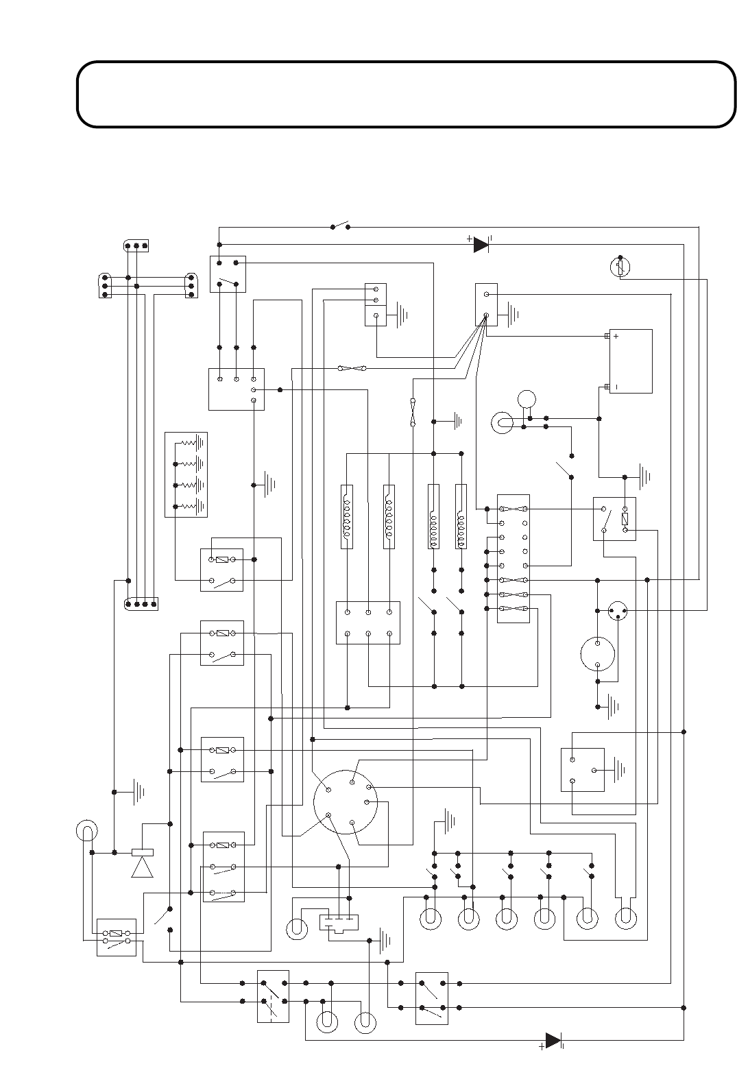
924916KG251004
ELECTRICAL CIRCUIT DIAGRAM
85
Y
Y
BL R
W/R
BL R
2
BL
50
50
50
G/R
G/W
G/R
G/W
R/W
BL
50
1
4
Y
86
BL/PU
R
BL
32
P
30
85
87
42
43
30 86
87a
R
B/G
BL
44
B/G
W/BL
45
BL B
31
BL BU
R
13 14 15 16
12
R/O
PU
BU/R
48 0BL
BLR
M
49
34
BL
B
B
B
BL
BL
51
17
19
20
W/PU
BL
18
B
PU
B
R
PU
R
1
2
3
4
5
6
BU/S
BU
BU/BL
21
B/BU
S
B/R
R/BU
P
W/B
87
30 86
85
5
W/B
B/R
7
G
G
R
D/G
G
B/R
53
30
87
86
85
PU/Y
8
BL
S
9
B/BU
52
Y
PU/Y
54
10
Y/BL
W/BU
57
11
19 58
15/54
50a
17
30
R
W
W/B
30
W
36
B
W/B
37
BL
Y
W/BU
33
4
8
7
1
0
BL
30 86
87 85
3
Y
28
26
38
40
24
23
R/BU
29
27
39
W/Y
W/G 41
W/PU 25
S
B/BU
R/Y
W/R
35
W/BL Y/BL W/BU
55
Y/BL
P
22
21
BL
BU/R
Y
W/R
W/BU
Y/BL
BU/Y
Y
BL
B/BL
BU
Y
6
56
Y
BL
Y
Y
B/BL
4P924C01
2
PU B46 BL R/PU 47
1.72 1.72

924916KG251004
ELECTRICAL CIRCUIT DIAGRAM
ITEM NO. DESCRIPTION.
1 Horn. 70-09-108
2 Relay - Neutral Start. 995713
3 Relay - Engine Coolant Temperature Warning. 70-09-148
4 Relay - Hydraulic Oil Temperature Warning. 70-09-148
5 Relay - Glow Plug. 924625
6 Glow Plugs - Engine. -
7 Timer. 70-01-512
8 Switch - Seat. 953819
9 Alternator / Regulator - Engine. -
10 Starter Motor - Engine. -
11 Battery. 70-09-015
12 Fuse Box. 70-09-096
13 Fuse - 10 Amp. 70-09-026
14 Fuse - 5 Amp. 70-09-025
15 Fuse - 3 Amp. 70-09-024
16 Fuse - 30 Amp. 70-09-027
17 Solenoid - Differential Lock. 910627
18 Switch - Differential Lock. 924624
19 Solenoid - Cutterhead Drive Front. 70-06-246
20 Solenoid - Cutterhead Drive Rear. 70-06-246
21 Switch - Cutterhead Drive. 924864
22 Hourmeter. 910850
23 Light - Battery Warning. 924605
24 Light - Engine Oil Pressure Warning. 924606
25 Switch - Engine Oil Pressure. -
26 Light - Engine Coolant Temperature Warning. 924602
27 Switch - Engine Coolant Temperature.-
28 Light - Hydraulic Oil Temperature Warning. 924603
29 Switch - Hydraulic Oil Temperature. 940852
30 Switch - Ignition. 74-09-009
31 Switch - Neutral Start. 995711
32 Switch - Horn. 924618
33 Switch - Parking Brake Interlock. 924624
34 Relay - Fuel Solenoid. 16259-60250
35 Solenoid - Engine Fuel. -
36 Glow Plug Timer 15694-65992
37 Glow Plug Lamp 924601/950857
38 Return Filter Lamp 924601/950866
39 Return Filter Switch -
40 Pressure Filter Lamp 924601/950863
41 Pressure Filter Switch -
42 Cutterhead Drive Off Lamp 924601/950861
43 Relay - Cutter Lamp Off 70-09-148
44 Neutral Lamp 924601/950862
45 Handbrake Lamp 924601/950858
46 Temp Gauge and Hour Meter (Kit) -
47 Sender - Temp (Kit) -
48 Switch - Beacon (Supplied with Beacon Kit) 924608
49 Rotating Beacon (Supplied with Beacon Kit) 70-01-493
50 Connectors for Lighting Kit -
51 Fuse - Main 50A 995714
52 Fuse - Engine Glow Plugs 50A 995714
53 Relay - Seat Switch 70-09-148
54 Diode - Seat Switch 950868
55 Diode - Parking Brake 950868
56 Temp Gauge & Hour Meter (Kit) -
57 Sender - Temp (Kit) -
1.73 1.73
Wire Colour Code
BBrown. WWhite.
GGreen. YYellow.
PPink. OOrange.
RRed. BU Blue.
SSlate Grey. BL Black.
PU Purple.
Example 2 Colour Wire:
BU/G - Blue / Green
Main Colour Trace Colour

924916KG251004
HYDRAULIC CIRCUIT DIAGRAM
1.74 1.74

924916KG251004
HYDRAULIC CIRCUIT DIAGRAM
ITEM NO.
1
2
3
4
5
6
7
8
9
10
11
12
13
14
15
16
17
18
19
20
21
22
23
24
25
26
27
28
29
30
31
32
33
34
35
36
37
38
39
40
41
42
43
44
45
46
47
48
49
50
51
52
53
54
DESCRIPTION. PART NO:
Axial Piston Pump - Variable Displacement. -
Charge Pump. -
Relief Valve - Charge Pump -18.5 bar. -
Mechanical Control. -
Relief Valve - Forward Travel - 300 bar. 940692
Relief Valve - Reverse Travel - 300 bar. 940692
Shuttle Valve - Load Sensing. 910629
Relief Valve - Hot Oil Purge. 910630
Shuttle Valve - Hot Oil Purge. 910628
Solenoid Valve - Difflock. 910626
Pilot Operated Diverter Valve - Difflock Front RH. 910625
Pilot Operated Diverter Valve - Difflock Front LH. 910625
Hydraulic Oil Tank. 910912
Flow Divider - Front Axle. 910624
Gear Pump - Steering and Cutterhead Lift. 910695
Front LH Wheel Motor - Pressure Release Disc Brake. 950620
Front RH Wheel Motor - Pressure Release Disc Brake. 950620
Steering Cylinder - Rear Axle. 70-01-195W
Brake Control Valve. 74-06-015W
Gear Pump - Cutterhead Drive. 910695
Check Valve - Transmission Forward Bypass. -
Check Valve - Transmission Reverse Bypass. -
Relief Valve - 110 bar. -
Check Valve - Oil Cooler Bypass - 4 bar. 910641
Oil Cooler. 70-06-171
Return Filter - Bypass Check Valve - 2 bar . 924865
Suction Strainer - No Bypass. 65-06-305
Pressure Filter - No Bypass. 950597
Hydraulic Motor - LH Front Cutterhead. 940602
Diverter Valve - LH Front Cutterhead. 953601
Hydraulic Motor - RH Front Cutterhead. 910696
Diverter Valve - RH Front Cutterhead. 953601
Hydraulic Motor - Centre Cutterhead. 940602
Diverter Valve - Centre Cutterhead. 953601
Rear Porting Manifold. 924687
Solenoid Valve - Forward/Reverse Check Valve 4WD. 924688
Relief Valve - Cutterheads - 250 bar. 910708
Solenoid Valve - Cutterhead Drive. 70-06-245
Restrictor Valve - Variable Weight Assist. 910709
Spool Valve - Cutterhead Lift LH. -
Spool Valve - Cutterhead Lift Centre. -
Spool Valve - Cutterhead Lift RH. -
Hydraulic Cylinder - LH Front Cutterhead. 910109
Hydraulic Cylinder - Centre Cutterhead. 910109
Hydraulic Cylinder - RH Front Cutterhead. 910109
Check Valve - Steering Shock Bypass RH. -
Check Valve - Steering Shock Bypass LH. -
Relief Valve - Steering Shock LH. -
Relief Valve - Steering Shock RH. -
Check Valve / Orifice - Motor Bypass LH Front Cutterhead. -
Check Valve / Orifice - Motor Bypass RH Front Cutterhead. -
Check Valve / Orifice - Motor Bypass Centre Cutterhead. -
Steering Unit. 910649W
Wheel Motor LH Rear. 70-01-018W
1.75 1.75

924916KG251004
HYDRAULIC CIRCUIT DIAGRAM
ITEM NO.
55
56
57
58
59
60
61
62
63
64
65
66
DESCRIPTION. PART NO:
Test Point - Transmission Reverse. 910615
Test Point - Transmission Forward. 910615
Test Point - Transmission Charge. 910615
Test Point - Cutterhead Drive. 910615
Test Point - Weight Transfer. 910615
Transmission Pump Assembly. 924690W
Transmission Manifold. 910602
Cooler Bypass Manifold. 910616
Valve - Cutter Sub Plate. 910699
Solenoid - Cutting Cylinders Reverse. 70-06-246
Solenoid - Cutting Cylinders Forwards. 70-06-246
Wheel Motor - RH Rear. 70-01-019W
1.76 1.76

924916KG251004
WARRANTY
WARRANTY
HAYTER LIMITED warrants to the original user / purchaser that this unit shall be free from defects in
material and workmanship for a period of 12 calendar months from the date of delivery. This warranty
excludes proprietary items which have the benefit of the supplying manufacturer’s warranty.
Engine manufacturers furnish their own warranties and provide services through their authorised network.
If you experience any difficulty please contact your specialist Hayter dealer.
It is the end user’s / purchaser’s responsibility to ensure that the service schedule and service book as
applied are acted upon. HAYTER LIMITED reserve the right to request inspection of a service book,
where relevant at any reasonable time. Failure to keep the service schedule up to date may invalidate the
warranty. Owners should therefore satisfy themselves that the products are operated and serviced correctly,
particularly where they are operated on a contract or hire basis.
This warranty which is not capable of assignment does not apply to any unit that has been tampered with,
altered, misused or abused and will become invalid if non genuine Hayter parts are fitted. This
warranty does not cover minor adjustments unless they are due to defective materials or workmanship.
Consult the operators manual or your authorised Hayter dealer for assistance when making these
adjustments.
To make a warranty claim, contact your authorised Hayter dealer through whom the machine was
originally supplied, indicating the machine serial number and purchase date. Subject to the conditions and
exclusions in this warranty, the authorised dealer will at our option, repair or replace any warranted part
within the duration of the warranty period.
This warranty gives you specific legal rights and is in addition to any statutory rights to which you may be
entitled and your statutory rights are not affected by this warranty. If you need additional information
concerning this written warranty or assistance in obtaining services please write or telephone : HAYTER
LIMITED, Service Department, Spellbrook, Bishop's Stortford, Herts., CM23 4BU.
Telephone : (01279) 723444.
1.77 1.77

924916KG251004
NOTES
1.78 1.78

924916KG251004
CUSTOMER INFORMATION
1.79 1.79
MACHINE DETAILS
Model:
Machine Serial No.:
Engine Serial No.:
Cutterhead Serial No.s:
Transmission Pump Serial No.:
Transmission Valve Block Front Serial No.:
Transmission Valve Block Rear Serial No.:
Cutter Control Valve Serial No.:

