Hayter Mowers Rt380H Users Manual
RT380H to the manual 2672b2c8-8d00-4d66-a5e1-960ab779da14
2015-02-09
: Hayter-Mowers Hayter-Mowers-Rt380H-Users-Manual-564605 hayter-mowers-rt380h-users-manual-564605 hayter-mowers pdf
Open the PDF directly: View PDF ![]() .
.
Page Count: 52

Operator ’sManual
RT380HTractor
withRecycling/SideDischargeDeck
G006889
Code135E
SerialNo.280000001ManualPartNo.111-2091RevC
Introduction
Readthisinformationcarefullytolearnhowtooperate
andmaintainyourproductproperlyandtoavoidinjury
andproductdamage.Youareresponsibleforoperating
theproductproperlyandsafely.
Wheneveryouneedservice,genuineparts,oradditional
information,contactanAuthorizedServiceDealer
orCustomerServiceandhavethemodelandserial
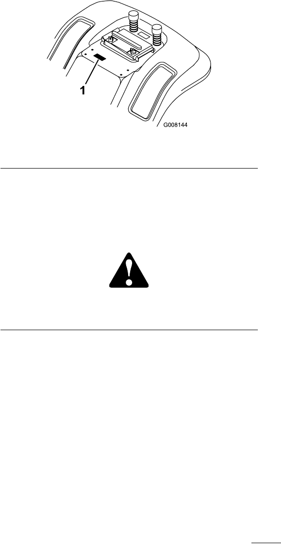
numbersofyourproductready.Figure1identiesthe
locationofthemodelandserialnumbersontheproduct.
1
G008144
Figure1
1.Modelandserialnumberlocation
Thismanualidentiespotentialhazardsandhas
safetymessagesidentiedbythesafetyalertsymbol
(Figure2),whichsignalsahazardthatmaycauseserious
injuryordeathifyoudonotfollowtherecommended
precautions.
Figure2
1.Safetyalertsymbol
Thismanualuses2wordstohighlightinformation.
Importantcallsattentiontospecialmechanical
informationandNoteemphasizesgeneralinformation
worthyofspecialattention.
Contents
Introduction.................................................................2
Safety...........................................................................3
SafeOperationPracticesforRide-on(Riding)
RotaryLawnMowers........................................3
SoundPressure.....................................................5
SoundPower........................................................5
Vibration..............................................................5
SlopeChart..........................................................6
SafetyandInstructionalDecals.............................7
Setup..........................................................................10
1InstallingtheFrontWheels..............................11
2CheckingtheTyrePressure..............................11
3InstallingtheSteeringWheel............................11
4InstallingtheSeat.............................................12
5ActivatingtheBattery......................................12
6CheckingtheEngineOilLevel.........................13
7InstallingtheAnti-ScalpWheels.......................13
8PreparingtheCutterDeckDischarge
Chute.............................................................14
9LubricatingtheTractor....................................14
10CheckingtheSafetyInterlockSystem..............14
11PurgingtheHydroTransaxle..........................14
12CheckingtheHydroNeutralPosition..............15
13CheckingtheTractionControlPedal..............15
ProductOverview......................................................16
Controls.............................................................16
Operation...................................................................17
PetrolandOil.....................................................17
UsingtheParkingBrake......................................18
PositioningtheSeat............................................18
OperatingtheHeadlights....................................18
OperatingtheBladeControl(PTO)....................19
SettingtheHeight-of-Cut...................................19
StartingtheEngine.............................................19
StoppingtheEngine...........................................20
UsingtheSafetyInterlockSystem.......................20
TestingtheSafetyInterlockSystem.....................21
PushingtheTractorManually.............................21
DrivingForwardorBackward.............................22
StoppingtheTractor...........................................22
SideDischargeorMulchGrass...........................22
InstallingtheDischargeCover............................22
OperatingTips...................................................23
Maintenance...............................................................24
RecommendedMaintenanceSchedule(s)................24
Lubrication.............................................................25
GreasingandLubricatingtheTractor..................25
EngineMaintenance...............................................25
ServicingtheEngineOil.....................................25
ServicingtheAirCleaner....................................26
ServicingtheSparkPlug.....................................27
©2008—HayterLimited,
2
AllRightsReserved

FuelSystemMaintenance.......................................28
DrainingtheFuelTank.......................................28
ReplacingtheFuelFilter.....................................29
ElectricalSystemMaintenance................................29
ServicingtheBattery...........................................29
ServicingtheFuse..............................................31
ServicingtheHeadlights.....................................31
DriveSystemMaintenance.....................................32
CheckingtheTyrePressure.................................32
ServicingtheTransaxleFluid..............................32
CoolingSystemMaintenance..................................33
CleaningtheCoolingSystem...............................33
BrakeMaintenance.................................................34
ServicingtheParkingBrake................................34
BeltMaintenance....................................................35
ReplacingtheBladeDriveBelt............................35
CutterDeckMaintenance.......................................35
ServicingtheBlades............................................35
LevelingtheCutterDeckfrom
Side-to-Side....................................................39
AdjustingtheFront-to-RearBladeSlope.............40
Cleaning.................................................................41
WashingtheUndersideoftheCutter
Deck..............................................................41
Storage.......................................................................42
Troubleshooting.........................................................44
Schematics.................................................................46
Safety
SafeOperationPracticesfor
Ride-on(Riding)RotaryLawn
Mowers
Readandunderstandthecontentsofthismanualbefore
operatingthetractor.
ThefollowinginstructionsarefromtheCENstandard
EN836:1997.
Thisproductiscapableofamputatinghandsandfeet
andofthrowingobjects.Alwaysfollowallsafety
instructionstoavoidseriousinjuryordeath.
Training
•Readtheinstructionscarefully.Befamiliarwiththe
controlsandtheproperuseoftheequipment.
•Neverallowchildrenorpeopleunfamiliarwiththese
instructionstousethelawnmower.Localregulations
canrestricttheageoftheoperator.
•Nevermowwhilepeople,especiallychildren,orpets
arenearby.
•Keepinmindthattheoperatororuserisresponsible
foraccidentsorhazardsoccurringtootherpeopleor
theirproperty.
•Donotcarrypassengers.
•Alldriversshouldseekandobtainprofessional
andpracticalinstruction.Suchinstructionshould
emphasize:
–theneedforcareandconcentrationwhen
workingwithride-onmachines;
–controlofaride-onmachineslidingonaslope
willnotberegainedbytheapplicationofthe
brake.Themainreasonsforlossofcontrolare:
◊insufcientwheelgrip;
◊beingdriventoofast;
◊inadequatebraking;
◊thetypeofmachineisunsuitableforitstask;
◊lackofawarenessoftheeffectofground
conditions,especiallyslopes;
◊incorrecthitchingandloaddistribution.
Preparation
•Whilemowing,alwayswearsubstantialfootwearand
longtrousers.Donotoperatetheequipmentwhen
barefootorwearingopensandals.
3

•Thoroughlyinspecttheareawheretheequipment
istobeusedandremoveallobjectswhichmaybe
thrownbythemachine.
•Warning—Fuelishighlyammable.
–Storefuelincontainersspecicallydesignedfor
thispurpose.
–Refueloutdoorsonlyanddonotsmokewhile
refuelling.
–Addfuelbeforestartingtheengine.Never
removethecapofthefueltankoraddfuelwhile
theengineisrunningorwhentheengineishot.
–Iffuelisspilled,donotattempttostartthe
enginebutmovethemachineawayfromthe
areaofspillageandavoidcreatinganysourceof
ignitionuntilfuelvaporshavedissipated.
–Replaceallfueltanksandcontainercapssecurely.
•Replacefaultysilencers.
•Beforeusing,alwaysvisuallyinspecttoseethatthe
blades,bladeboltsandcutterassemblyarenotworn
ordamaged.Replacewornordamagedbladesand
boltsinsetstopreservebalance.
•Onmulti-bladedmachines,takecareasrotatingone
bladecancauseotherbladestorotate.
Operation
•Donotoperatetheengineinaconnedspacewhere
dangerouscarbonmonoxidefumescancollect.
•Mowonlyindaylightoringoodarticiallight.
•Beforeattemptingtostarttheengine,disengageall
bladeattachmentclutchesandshiftintoneutral.
•Donotuseonslopesofmorethan
–5°whenmowingonsidehills;
–10°whenmowinguphill;
–15°whenmowingdownhill.
•Rememberthereisnosuchthingasasafeslope.
Travelongrassslopesrequiresparticularcare.To
guardagainstoverturning:
–donotstoporstartsuddenlywhengoingupor
downhill;
–engageclutchslowly,alwayskeepmachinein
gear,especiallywhentravellingdownhill;
–machinespeedsshouldbekeptlowonslopes
andduringtightturns;
–stayalertforhumpsandhollowsandother
hiddenhazards;
–nevermowacrossthefaceoftheslope,unless
thelawnmowerisdesignedforthispurpose.
•Usecarewhenpullingloadsorusingheavy
equipment.
–Useonlyapproveddrawbarhitchpoints.
–Limitloadstothoseyoucansafelycontrol.
–Donotturnsharply.Usecarewhenreversing.
–Usecounterweight(s)orwheelweightswhen
suggestedintheinstructionhandbook.
•Watchoutfortrafcwhencrossingornearroadways.
•Stopthebladesrotatingbeforecrossingsurfaces
otherthangrass.
•Whenusinganyattachments,neverdirectdischarge
ofmaterialtowardbystandersnorallowanyonenear
themachinewhileinoperation.
•Neveroperatethemachinewithdamagedguardsor
withoutsafetyprotectivedevicesinplace.
•Donotchangetheenginegovernorsettingsor
overspeedtheengine.Operatingtheengineat
excessivespeedcanincreasethehazardofpersonal
injury.
•Beforeleavingtheoperator’sposition:
–disengagethepowertake-offandlowerthe
attachments;
–changeintoneutralandsettheparkingbrake;
–stoptheengineandremovethekey.
•Disengagedrivetoattachments,stoptheengine,
anddisconnectthesparkplugwire(s)orremovethe
ignitionkey
–beforeclearingblockagesoruncloggingchute;
–beforechecking,cleaningorworkingonthelawn
mower;
–afterstrikingaforeignobject.Inspectthelawn
mowerfordamageandmakerepairsbefore
restartingandoperatingtheequipment;
–ifthemachinestartstovibrateabnormally(check
immediately).
•Disengagedrivetoattachmentswhentransporting
ornotinuse.
•Stoptheengineanddisengagedrivetoattachment
–beforerefuelling;
–beforeremovingthegrasscatcher;
–beforemakingheightadjustmentunless
adjustmentcanbemadefromtheoperator’s
position.
4

•Reducethethrottlesettingduringenginerun-out
and,iftheengineisprovidedwithashut-offvalve,
turnthefueloffattheconclusionofmowing.
•UseonlyHayter-approvedattachments.The
warrantymaybevoidedifyouusethetractorwith
unapprovedattachments.
MaintenanceandStorage
•Keepallnuts,boltsandscrewstighttobesurethe
equipmentisinsafeworkingcondition.
•Neverstoretheequipmentwithfuelinthetank
insideabuildingwherefumescanreachanopen
ameorspark.
•Allowtheenginetocoolbeforestoringinany
enclosure.
•Toreducetherehazard,keeptheengine,silencer,
batterycompartmentandfuelstorageareafreeof
grass,leaves,orexcessivegrease.
•Replacewornordamagedpartsforsafety.
•Ifthefueltankhastobedrained,thisshouldbe
doneoutdoors.
•Onmulti-bladedmachines,takecareasrotatingone
bladecancauseotherbladestorotate.
•Whenmachineistobeparked,storedorleft
unattended,lowerthecuttingmeansunlessapositive
mechanicallockisused.
SoundPressure
Thisunithasamaximumsoundpressurelevelatthe
operator’searof89dBA,basedonmeasurementsof
identicalmachinesperEN836andISO11201.
SoundPower
Thisunithasaguaranteedsoundpowerlevelof100
dBA,basedonmeasurementsofidenticalmachinesper
ISO11094.
Vibration
Thisunitdoesnotexceedahand/armvibrationlevelof
2.4m/s2,basedonmeasurementsofidenticalmachines
perEN836andEN1033.
Thisunitdoesnotexceedawholebodyvibration
levelof0.5m/s2,basedonmeasurementsofidentical
machinesperEN836andEN1032.
5
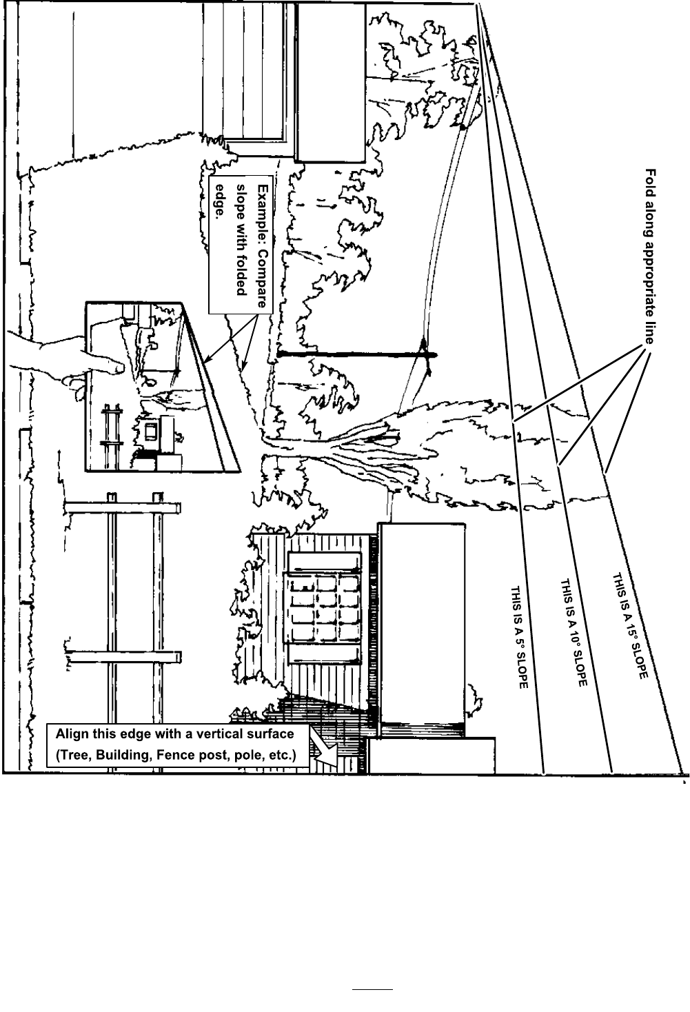
SlopeChart
6
SafetyandInstructionalDecals
Safetydecalsandinstructionsareeasilyvisibletotheoperatorandarelocatednearanyareaof
potentialdanger.Replaceanydecalthatisdamagedorlost.
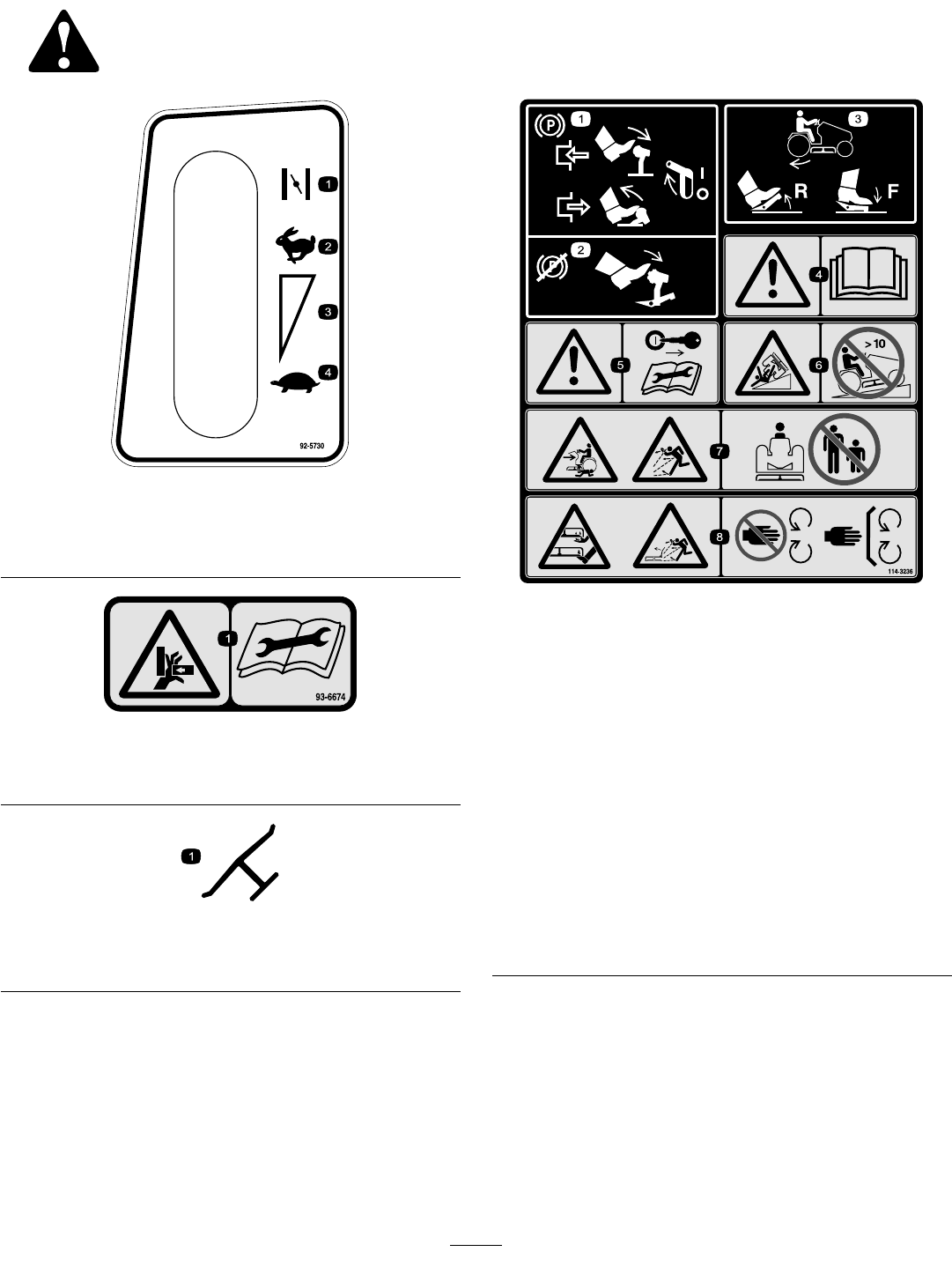
92-5730
1.Choke3.Continuousvariable
setting
2.Fast4.Slow
93-6674
1.Crushinghazard,hand—readtheinstructionsbefore
servicingorperformingmaintenance.
Manufacturer’sMark
1.Indicatesthebladeisidentiedasapartfromtheoriginal
machinemanufacturer.
114-3236
1.Parkingbrake—toengage,pressthebrake/clutchpedal
andlifttheparkingbrakelever;todisengagepressand
releasethebrake/clutchpedal.
2.Brakeandclutch—toengage,pressthebrake/clutchpedal.
3.Tractiondrive—todriveinreverse,pressthebottomofthe
tractioncontrolpedalrearwardanddown;todriveforward,
pressthetopofthetractioncontrolpedalforwardanddown.
4.Warning—readtheOperator’sManual.
5.Warning—removetheignitionkeyandreadtheinstructions
beforeservicingorperformingmaintenance.
6.Tippinghazard—donotusethemachineonaslopegreater
than10degrees.
7.Crushing/dismembermentofabystander;thrownobject
hazard—keepbystandersasafedistancefromthe
machine.
8.Cutting/dismembermenthazardofhandorfoot,mower
blade;thrownobjecthazard,mower—stayawayfrom
movingparts;keepallguardsandshieldsinplace.
7
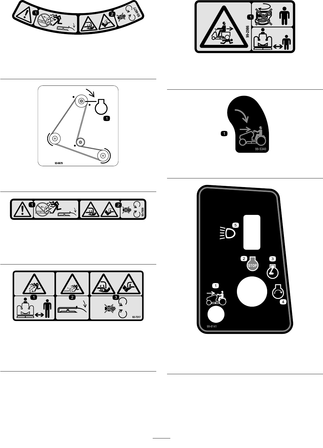
93-6677
1.Warning—don’toperatethemowerwiththedeectorupor
removed;keepthedeectorinplace.
2.Cutting/dismembermenthazardofhandorfoot,mower
blade—stayawayfrommovingparts.
93-6679
1.Engine
93-7009
1.Warning—don’toperatethemowerwiththedeectorupor
removed;keepthedeectorinplace.
2.Cutting/dismembermenthazardofhandorfoot,mower
blade—stayawayfrommovingparts.
93-7317
1.Thrownobjecthazard—keepbystandersasafedistance
fromthemachine.
2.Thrownobjecthazard,mower—keepthedeectorinplace.
3.Cutting/dismembermentofhandorfoot—stayawayfrom
movingparts.
99-2986
1.Crushing/dismembermenthazardofbystanders—donot
turnthekeywhilechildrenarepresent;keepchildrenasafe
distancefromthemachine.
99-5340
1.Reverseinterlockkey—turntoenablereversemowing.
99-8141
1.Mowinginreverseenabled4.Engine—Start
2.Engine—Stop5.Headlights
3.Engine—Run
8
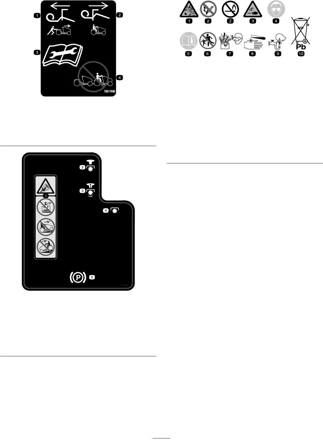
100-7449
1.Pulltheleverouttopush
themachine.
3.Readtheinstructions
beforeservicingor
performingmaintenance.
2.Pushtheleverintorideon
themachine.
4.Donottowthemachine.
107-4922
1.Warning—toavoidtippingthetractor,donotdriveacross
slopesgreaterthan5degrees,upslopesgreaterthan10
degrees,ordownslopesgreaterthan15degrees.
2.Disengage
3.Engage
4.Powertake-off(PTO)
5.Parkingbrake
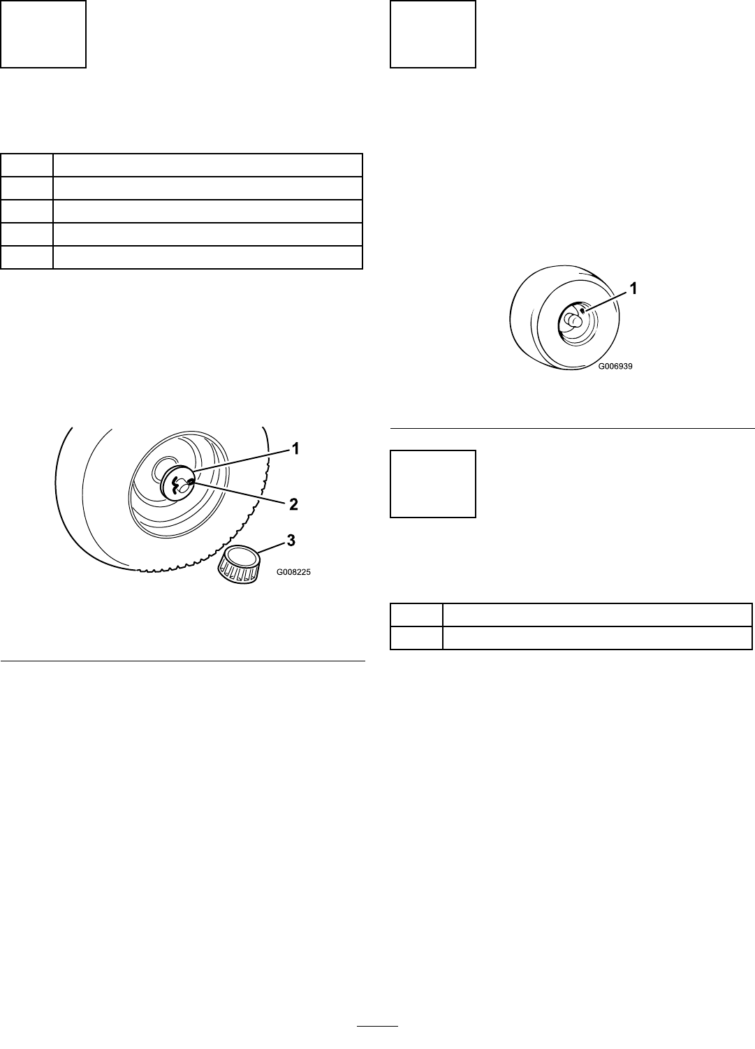
BatterySymbols
Someorallofthesesymbolsareonyourbattery
1.Explosionhazard6.Keepbystandersasafe
distancefromthebattery.
2.Nore,opename,or
smoking.
7.Weareyeprotection;
explosivegasescan
causeblindnessandother
injuries
3.Causticliquid/chemical
burnhazard
8.Batteryacidcancause
blindnessorsevereburns.
4.Weareyeprotection9.Flusheyesimmediately
withwaterandgetmedical
helpfast.
5.ReadtheOperator’s
Manual.
10.Containslead;donot
discard.
9

Setup
LooseParts
Usethechartbelowtoverifythatallpartshavebeenshipped.
ProcedureDescriptionQty.Use
Frontwheels2
Shimwashers(asrequired)2
Flatwashers2
Cotterpins2
1
Hubcaps2
Installthefrontwheels.
2Nopartsrequired–Checkthetyrepressure.
Steeringwheel1
3Spirolpin1Installthesteeringwheel.
Seat1
Knobs2
4Flat-washer2
Installtheseat.
Bulkelectrolyte,1.260specicgravity
(purchaseseparately)
As
needed
Bolt(1/4x3/4inch)2
5Wingnut2
Activatethebattery.
6Nopartsrequired–Checktheengineoillevel.
Anti-scalpwheels2
Wheelbolt2
7Locknut2
Installtheanti-scalpwheels.
8Nopartsrequired–Preparingthecutterdeckdischarge
chute.
9Nopartsrequired–Lubricatethetractor.
10Nopartsrequired–Checkthesafetyinterlocksystem.
11Nopartsrequired–Purgethehydrotransaxle,
12Nopartsrequired–Checkthehydroneutralposition.
13Nopartsrequired–Checkthetractioncontrolpedal.
MediaandAdditionalParts
DescriptionQty.Use
Ignitionkey1Starttheengine.
Reverseinterlockkey1Enablemowingoperationinreverse.
Liftassistspringremovaltool1Saveforfuturemaintenanceuse.
Operator’sManual1Readbeforeoperating.
CerticateofConformance1
Noisecerticate1CEconformance
10
1
InstallingtheFrontWheels
Partsneededforthisprocedure:
2Frontwheels
2Shimwashers(asrequired)
2Flatwashers
2Cotterpins
2Hubcaps
Procedure
1.Installtheshimwashersontotheaxle.
2.Installthewheelontotheaxlewiththevalvestem
facingout.
3.Slidetheatwasherontotheaxle(Figure3).
Figure3
1.Flatwasher3.Hubcap
2.Cotterpin
4.Insertthecotterpinthroughtheaxleandbendthe
endsofthepinapart(Figure3).
Note:Ifthecotterpindoesnott,removethe
shimwasher(s)asneeded.
5.Pushthehubcap(Figure3)ontotheendoftheaxle.
6.Repeatsteps1through5ontheoppositesideof
thetractor.
7.Greasethewheelbearingsuntilthegreasecomesout
ofthebearingsealarea.
2
CheckingtheTyrePressure
NoPartsRequired
Procedure
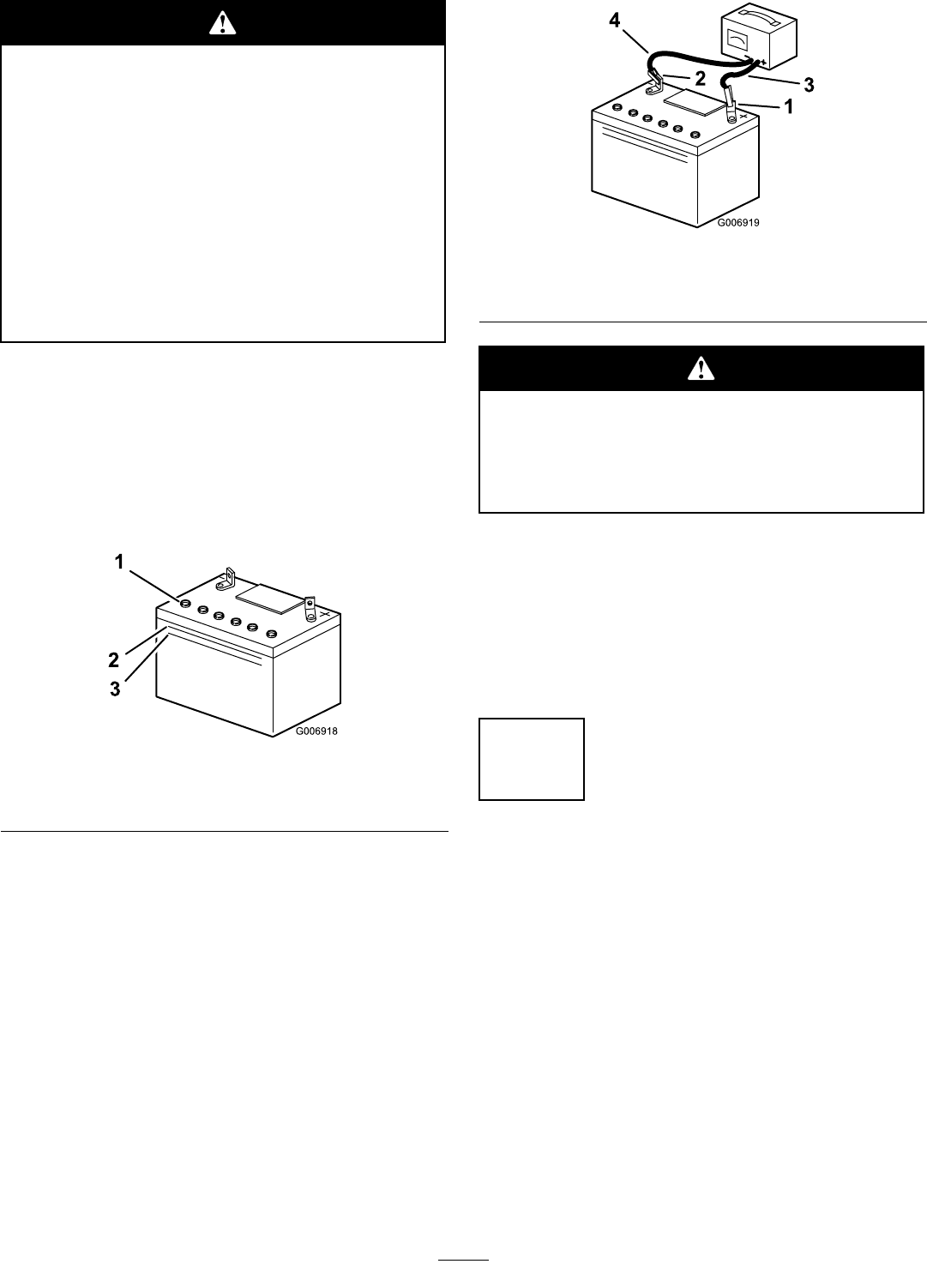
Ensurethattheairpressureinthefrontandreartyres
are20psi(138kPa).Checkthepressureatthevalve
stem(Figure4).
Figure4
1.Valvestem
3
InstallingtheSteeringWheel
Partsneededforthisprocedure:
1Steeringwheel
1Spirolpin
Procedure
1.Movethefrontwheelssothattheyfacestraight
ahead.
2.Slidethesteeringwheeloverthesteeringshaftand
lineuptheholeinthesteeringwheelwiththeholein
theshaft(Figure5).
Note:Fromtheseatyoushouldbeabletoreadthe
brandlogoonthesteeringwheel.
11
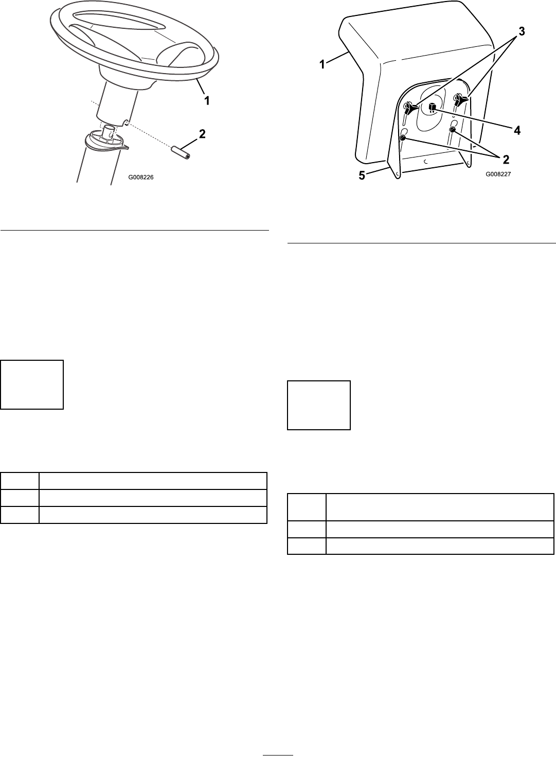
Figure5
1.Steeringwheel2.Spirolpin
3.Aligntheholesbyinsertingapunchoralongnail
partiallythroughtheholesinthesteeringwheeland
shaft.
4.Insertthespirolpinintotheholeontheopposite
side(Figure5).
5.Usingahammer,drivethespirolpininuntilitisush
withtheoutsideofthesteeringwheel(Figure5).
4
InstallingtheSeat
Partsneededforthisprocedure:
1Seat
2Knobs
2Flat-washer
Procedure
1.Positiontheseatontotheseatbasebyinserting2
shoulderboltsthroughthekeyholeopeningsatthe
endofbothslots(Figure6).
Figure6
1.Seat4.Seatswitch
2.Shoulderbolts5.Seatbase
3.Knobsandatwashers
2.Threadtheknobsandatwashersthroughtheslots
andintotherearcenterholesintheseat(Figure6).
3.Adjusttheseatandtightentheknobs.
4.Connecttheseatswitchtothewireharness
connector(Figure6).
Note:Ensurethatthewiringisnotpinchedinthe
seatbrackets.
5
ActivatingtheBattery
Partsneededforthisprocedure:
As
needed
Bulkelectrolyte,1.260specicgravity(purchase
separately)
2Bolt(1/4x3/4inch)
2Wingnut
Procedure
Purchasebulkelectrolytewith1.260specicgravity
fromalocalbatterysupplyoutlet.
Important:Neverllthebatterywithelectrolyte
whilethebatteryisinstalledinthetractor.
Electrolytecouldbespilledonotherpartsand
corrodethem.
1.Removethebatteryandbatteryboxfromthetractor;
refertoRemovingtheBatteryinMaintenance.
12
Batteryelectrolytecontainssulfuricacid,a
deadlypoisonthatcanseverelyburnyouand
others.
•Donotdrinkelectrolyteandavoidcontact
withskin,eyes,orclothing.Wearsafety
glassestoshieldyoureyesandrubbergloves
toprotectyourhands.
•Fillthebatterywherecleanwaterisalways
availableforushingtheskin.
•Followallinstructionsandcomplywithall
safetymessagesontheelectrolytecontainer.
2.Removetheventcapsfromthebattery.
3.Slowlypourelectrolyteintoeachbatterycelluntil
theelectrolytelevelisuptotheUpperlineonthe
batterycase(Figure7).
Important:Donotoverllthebatterybecause
electrolyte(sulfuricacid)canseverelycorrode
anddamagethechassis.
Figure7
1.Ventcaps3.Lowerline
2.Upperline
4.Wait5to10minutesafterllingthebatterycells.
5.Addelectrolyte,ifnecessary,untiltheelectrolytelevel
isuptotheUpperline(Figure7)onthebatterycase
6.Installthebatteryventcaps.
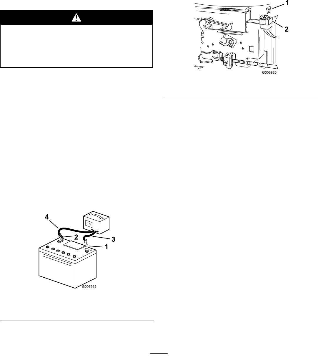
7.Chargethebatteryfor10to15minutesat25to30
ampsor30minutesat4to6amps(Figure8).Do
notoverchargethebattery.
Figure8
1.Positivepost3.Chargerred(+)wire
2.Negativepost4.Chargerblack(–)wire
Chargingthebatteryproducesgassesthatcan
explode.
Neversmokenearthebatteryandkeepsparks
andamesawayfromthebattery.
8.Whenthebatteryisfullycharged,unplugthecharger
fromtheelectricaloutlet,thendisconnectthe
chargerleadsfromthebatteryposts(Figure8).
9.Installthebatteryandbatteryboxinthetractorand
connectthebatterycables,usingthe2bolts(1/4x
3/4inch)andwingnutssuppliedinthelooseparts;
refertoInstallingtheBatteryinMaintenance.
6
CheckingtheEngineOilLevel
NoPartsRequired
Procedure
Beforeyoustarttheengineandusethetractor,check
theoillevelintheenginecrankcase;refertoChecking
theEngineOilLevel,inMaintenance.
13

7
InstallingtheAnti-Scalp
Wheels
Partsneededforthisprocedure:
2Anti-scalpwheels
2Wheelbolt
2Locknut
Procedure
Mounttheanti-scalpwheelsontothewheelbrackets
withthewheelboltsandlocknut(Figure9).
Figure9
1.Wheel3.Locknut
2.Wheelbracket4.Wheelbolt
Note:Usethesameholeheightonbothsides.
8
PreparingtheCutterDeck
DischargeChute
NoPartsRequired
Procedure
1.Removetherollpinfromthedischargechutespring
anddiscardthepin.
Note:Therollpinisforshipmentonly
2.Ensurethatthespringreturnsthedischargechute
tothefulldownposition.
9
LubricatingtheTractor
NoPartsRequired
Procedure
Ensurethatallofthenecessarypointsonthetractorare
lubricated;refertoGreasingandLubricatingtheTractor
inMaintenance.
10
CheckingtheSafetyInterlock
System
NoPartsRequired
Procedure
Checkthesafetyinterlocksystem;refertoTestingthe
SafetyInterlockSysteminOperation.
11
PurgingtheHydroTransaxle
NoPartsRequired
Procedure
Shippingandhandlingcanintroduceairintothehydro
transaxle.Forproperperformance,removeallthe
trappedair.
1.Movethetractortoaat,levelsurface
2.PlacethedrivecontrolinthePushposition
(Figure10).
14
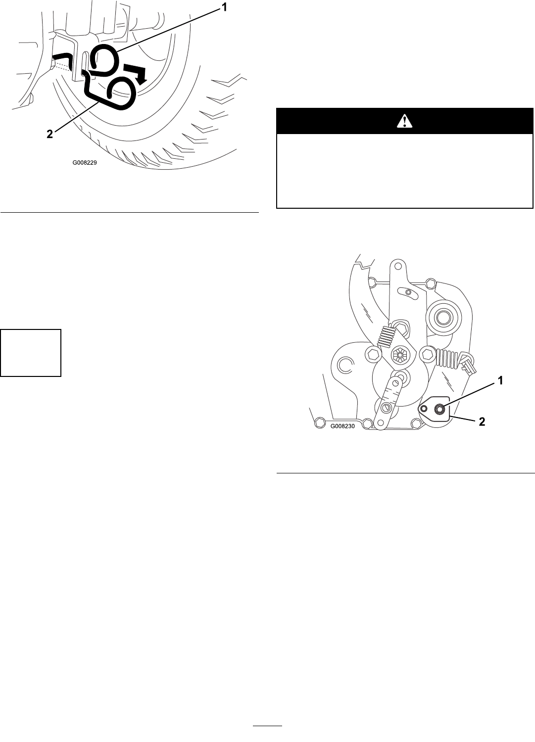
Figure10
1.Operateposition2.Pushposition
3.Runtheengineatalowidleandmovethetraction
controlpedalforwardfor5seconds,thenreversefor
5seconds.Repeatthisstep3times.
4.PlacethedrivecontrolintheOperateposition
(Figure10)anddrivethetractorforwardabout5
feet(1.5m),thenreverseforabout5feet(1.5m).
Repeatthisstep3times.
12
CheckingtheHydroNeutral
Position
NoPartsRequired
Procedure
Ensurethattheneutralpositionissetproperly.Ifthe
tractormoveswhenthetractioncontrolpedalisnot
pressed,adjusttheneutralposition.
1.WiththetractorintheNeutralposition,runthe
engineatalowidleandmovethetractioncontrol
pedalforward,thenrelease.
2.Movethetractioncontrolpedaltoreverse,then
release.
IfthetractormoveswhileitisintheNeutralposition,
completethefollowingproceduretoadjustit:
1.Runthetractorfor5to10minutestowarmupthe
transaxle.
2.Disengagetheblade(PTO).
3.Settheparkingbrake.
4.Stoptheengineandwaitforallmovingpartstostop.
5.Removetheignitionkey.
6.Raisetherightrearwheeloffthegroundandsupport
itwithajackstand.
Note:Ensurethattheleftrearwheelstaysonthe
ground.
Mechanicalorhydraulicjacksmayfailto
supportthetractorandcauseaseriousinjury.
•Usejackstandswhensupportingthetractor.
•Donotusehydraulicjacks.
Note:Togainaccesstotheadjustingpuck
(Figure11),youmayneedtoremovethetire.
Figure11
1.Adjustingpuckscrew2.Adjustingpuck
7.Loosentheadjustingpuckscrew(Figure11).
8.Starttheengineandrunitatfullthrottle.
9.Rotatetheadjustingpuck(Figure11)inboth
directionsuntilyoundthemidpointwheretheaxle
nolongerrotatesforwardorreverse.
10.Holdthepuckwithanadjustablewrenchsothatit
willnotmoveandtorquetheadjustingpuckscrew
to21to27ft-lb(28to36N-m).
11.Stoptheengineandwaitforallmovingpartstostop
12.Removetheignitionkey.
13.Lowerthetractorfromthejackstand.
14.Checktheadjustment.
15
13
CheckingtheTractionControl
Pedal
NoPartsRequired
Procedure
Ifthetractordrivestoofastorslowwiththetraction
controlpedalfullypressedineitherdirection,youcan
adjustittosettheoptimumforwardandreversespeeds,
asfollows:
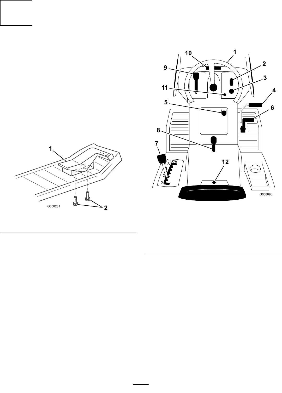
1.Loosenthescrewsbelowtherightfootrest.
2.Slidethepedalforwardforafasterreversespeedor
backwardforafasterforwardspeed(Figure12).
Figure12
1.Tractioncontrolpedal2.Adjustingscrews
3.Tightenthescrews.
4.Checkthetractioncontrolpedal.
ProductOverview
Controls
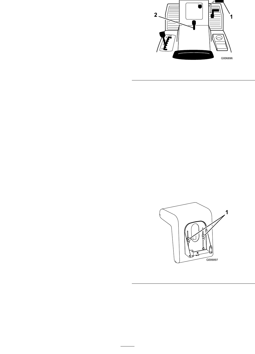
Becomefamiliarwiththecontrols(Figure13)before
youstarttheengineandoperatethetractor.
Figure13
1.Steeringwheel7.Height-of-cutlever
2.Lightswitch—on/off8.Parkingbrakelever
3.Ignitionswitch9.Throttlelever
4.Clutch/brakepedal10.Hoodopening
5.Bladecontrol(PTO)11.Operating-in-reverselight
6.Tractioncontrolpedal12.Reverseinterlockswitch
16

Operation
Note:Determinetheleftandrightsidesofthe
machinefromthenormaloperatingposition.
PetrolandOil
Useunleadedpetrolsuitableforautomotiveuse(85
pumpoctaneminimum).
Incertainconditions,petrolisextremely
ammableandhighlyexplosive.Areor
explosionfrompetrolcanburnyouandothers
andcandamageproperty.
•Fillthefueltankoutdoorsinanopenarea
whentheengineiscold.Wipeupanypetrol
thatspills.
•Donotllthefueltankcompletelyfull.Add
petroltothefueltankuntilthelevelis1/4to
1/2inch(6to13mm)belowthebottomof
thellerneck.Thisemptyspaceinthetank
allowsthepetroltoexpand.
•Neversmokewhenhandlingpetrol,andstay
awayfromanopenameorwhereaspark
mayignitethepetrolfumes.
•Storepetrolinanapprovedcontainerand
keepitoutofthereachofchildren.
•Neverbuymorethana30-daysupplyof
petrol.
•Alwaysplacepetrolcontainersonthe
groundawayfromyourvehiclebeforelling.
•Donotllpetrolcontainersinsideavehicle
oronatruckortrailerbedbecauseinterior
carpetsorplastictruckbedlinersmay
insulatethecontainerandslowthelossof
anystaticcharge.
•Whenpractical,removeequipmentfromthe
truckortrailerandrefueltheequipment
withitswheelsontheground.
•Ifthisisnotpossible,refuelsuchequipment
onatruckortrailerfromaportable
container,notfromapetroldispenser
nozzle.
•Ifyoumustuseapetroldispenser,keepthe
nozzleincontactwiththerimofthefuel
tankorcontaineropeningatalltimesuntil
fuelingiscomplete.
UsingStabilizer/Conditioner
Useafuelstabilizer/conditionerinthetractorto
providethefollowingbenets:
•Itkeepspetrolfreshduringstorageforupto90
days.Forlongerstorage,drainthefueltank.
17
•Itcleanstheenginewhileitruns.
•Iteliminatesgum-likevarnishbuildupinthefuel
system,whichcauseshardstarting.
Important:Donotusefueladditivescontaining
methanolorethanol.
Addthecorrectamountoffuelstabilizer/conditioner
tothepetrol.
Note:Afuelstabilizer/conditionerismosteffective
whenitismixedwithfreshpetrol.Tominimizethe
chanceofvarnishdepositsinthefuelsystem,useafuel
stabilizer/conditioneratalltimes.
FillingtheFuelTank
1.Settheparkingbrake.
2.Stoptheengine,removethekey,andwaitforall
movingpartstostopbeforeleavingtheoperating
position.
3.Cleanaroundthefueltankcapandremovethecap.
4.Addunleadedpetroltothefueltankuntilthe
levelis1/4to1/2inch(6to13mm)belowthe
bottomofthellerneck.Donotllthefueltank
completelyfull.
Note:Thespaceinthetankallowspetrolto
expand.
5.Installthefueltankcapsecurely.
6.Wipeupanypetrolthatspills.
CheckingtheEngineOilLevel
ServiceInterval:Beforeeachuseordaily
Beforeyoustarttheengineandusethetractor,check
theoillevelintheenginecrankcase;refertoChecking
theEngineOilLevel,inMaintenance.
UsingtheParkingBrake
Alwayssettheparkingbrakewheneveryoustopthe
tractororleaveitunattended.
SettingtheParkingBrake
1.Pushthebrakepedal(Figure14)downandholdit.
Figure14
1.Brakepedal2.Parkingbrakelever
2.Lifttheparkingbrakelever(Figure14)upand
graduallytakeyourfootoffofthebrakepedal.
Note:Thebrakepedalshouldstayinthedepressed
(locked)position.
ReleasingtheParkingBrake
1.Pushdownonthebrakepedal(Figure14).
Note:Theparkingbrakelevershouldrelease.
2.Graduallyreleasethebrakepedal.
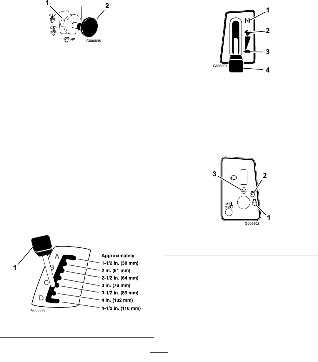
PositioningtheSeat
Theseatcanmoveforwardandbackward.Position
theseatwhereyouhavethebestcontrolofthetractor
andaremostcomfortable.
1.Raisetheseatandloosentheadjustmentknobs
(Figure15).
Figure15
1.Adjustmentknobs
2.Movetheseattothedesiredpositionandtighten
theknobs.
OperatingtheHeadlights
Adash-mountedOn/Offswitch(Figure13)controls
theheadlights.Thelightsonlyshinewhiletheengineis
runningandtheswitchisOn.
18
OperatingtheBladeControl
(PTO)
Thebladecontrol(PTO)engagesanddisengages
powertotheelectricclutch.
EngagingthePowerTakeOff(PTO)
1.Presstheclutch/brakepedaltostopthetractor.
2.Pullthebladecontrol(PTO)toon(Figure16).
Figure16
1.Off—disengaged2.On—engaged
DisengagingtheBladeControl(PTO)
1.Presstheclutch/brakepedaltostopthetractor.
2.Pushthebladecontrol(PTO)tooff(Figure16).
SettingtheHeight-of-Cut
Usetheheight-of-cutlevertoraiseandlowerthe
cutterdecktothedesiredcuttingheight.Youcan
settheheight-of-cuttooneofsevenpositionsfrom
approximately1-1/2to4-1/2inches(38to116mm).
1.Parkthemachineonalevelsurface.
2.Disengagethebladecontrol(PTO).
3.Settheparkingbrake.
4.Stoptheengine,removethekey,andwaitforall
movingpartstostopbeforeleavingtheoperating
position.
5.Pullontheheight-of-cutleveronthetractorand
moveittothedesiredposition(Figure17).
Figure17
1.Height-of-cutlever
StartingtheEngine
1.Sitdownontheseat.
2.Settheparkingbrake;refertoSettingtheParking
Brake.
Note:Theenginedoesnotstartunlessyousetthe
parkingbrakeorfullydepressthebrakepedal.
3.Pushthebladecontrol(PTO)tooff(Figure16).
4.ShiftthethrottlelevertoChoke(Figure18).
Figure18
1.Choke3.Slow
2.Fast4.Throttlelever
Note:Anenginethathasbeenrunningandis
warmmaynotrequirestep4.
5.Turntheignitionkeyclockwiseandholditinthe
Startposition(Figure19).Whentheenginestarts,
releasethekey.
Figure19
1.Start3.Off
2.On
Important:Iftheenginedoesnotstartafter
30secondsofcontinuouscranking,turnthe
ignitionkeytoOffandletthestartermotor
cool;refertoTroubleshooting.
6.Aftertheenginestarts,slowlyshiftthethrottlelever
toFast(Figure18).Iftheenginestallsorhesitates,
shiftthethrottleleverbacktoChokeforafew
secondsandthenshiftthethrottlelevertoFast.
Repeatthisstepasrequired.
19

StoppingtheEngine
1.ShiftthethrottlelevertoFast(Figure18).
2.TurntheignitionkeytoOff,waitforallmoving
partstostop,andremovethekeybeforeleavingthe
operatingposition.(Figure19).
UsingtheSafetyInterlock
System
ServiceInterval:Beforeeachuseordaily
Ifthesafetyinterlockswitchesaredisconnected
ordamaged,thetractorcouldoperate
unexpectedly,causingpersonalinjury.
•Donottamperwiththeinterlockswitches.
•Checktheoperationoftheinterlock
switchesdailyandreplaceanydamaged
switchesbeforeoperatingthetractor.
UnderstandingtheSafetyInterlock
System
Thesafetyinterlocksystemisdesignedtopreventthe
enginefromstartingunless:
•Youaresittingontheseat.
•Thebrakepedalisdepressed.
•Thebladecontrol(PTO)isintheDisengage
position.
Thesafetyinterlocksystemisdesignedtostopthe
engineifyoudothefollowing:
•Yourisefromtheseatwhenthebrakepedalis
released.
•Yourisefromtheseatwhilethebladecontrol
(PTO)isintheEngageposition.
•Youshiftintoreversewhilethebladecontrol(PTO)
isintheEngageposition.
SettingtheTractortoOperatein
Reverse
Aninterlockfeatureonthetractorpreventsthepower
take-off(PTO)fromoperatingwhenyoubackup
thetractor.Ifyoushiftthetractioncontrolswitch
intoReversewiththebladecontrol(PTO)engaged
(i.e.,withthecutterdeckbladesorotherattachment
running),theenginewillstop.Donotmowinreverse
unlessitisabsolutelynecessary.
Ifyouneedtousethebladecontrol(PTO)while
backingup,turnofftheinterlockfeatureusingthe
reverseinterlockswitchlocatedneartheseatbracket
(Figure20).
1
G006903
Figure20
1.Reverseinterlockswitch
Youcouldbackoverachildorbystanderwhile
thecutterdeckbladesorotherattachmentis
engagedandcauseseriousinjuryordeath.
•Donotmowinreverseunlessitisabsolutely
necessary.
•Donotinsertthereverseinterlockkey
unlessitisabsolutelynecessary.
•Alwayslookbackwardanddownbefore
backingup.
•Usethereverseinterlockswitchonlyifyou
arecertainnochildrenorotherbystanders
willenterthemowingarea.
•Beveryobservantafterdeactivatingthe
interlockbecausethesoundoftheengine
maypreventyoufromnoticingthatachild
orbystanderhasenteredtheworkarea.
•Alwaysremoveboththeignitionandreverse
interlockkeysandputtheminasafeplace
outofthereachofchildrenorunauthorized
userswhenleavingthetractorunattended.
1.Engagethebladecontrol(PTO).
2.Insertthereverseinterlockkeyintotheswitch
(Figure20).
3.Turnthereverseinterlockkey.
Note:Aredlightonthefrontconsole(Figure21)
turnson,indicatingthattheinterlockisdisabled.
20
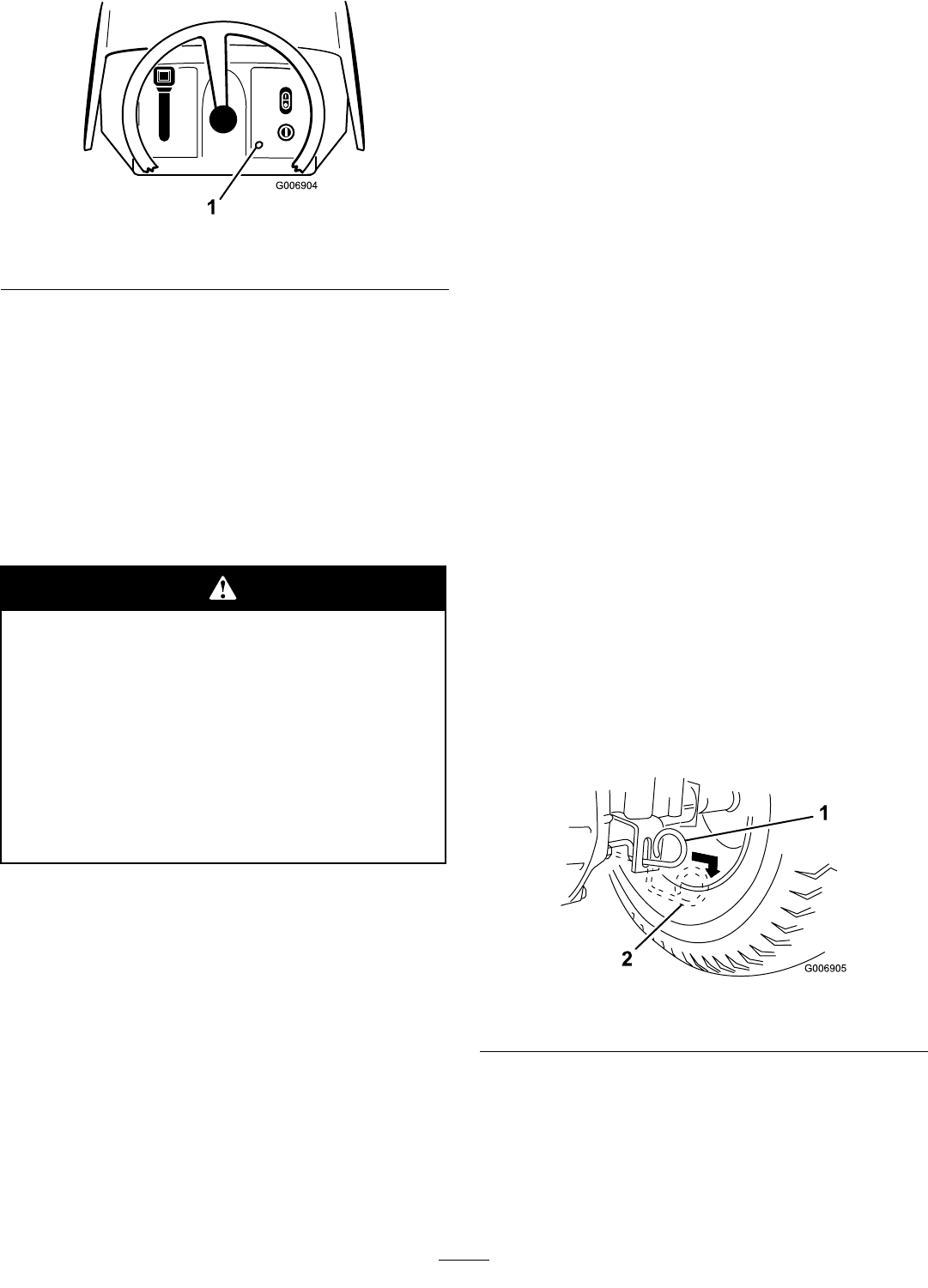
Figure21
1.Operating-in-reverselight
4.ShiftthetractioncontrolswitchintoReverseand
completeyourtask.
5.Disengagethebladecontrol(PTO)toactivatethe
interlock.
6.Removethereverseinterlockkeyandputitinasafe
placeoutofthereachofchildren.
TestingtheSafetyInterlock
System
Ifsafetyinterlockswitchesaredisconnected
ordamaged,thetractorcouldoperate
unexpectedly,causingpersonalinjury.
•Donottamperwiththeinterlockswitches.
•Checktheoperationoftheinterlock
switchesdailyandreplaceanydamaged
switchesbeforeoperatingthetractor.
•Replaceswitchesevery2yearsregardlessof
whethertheyareoperatingproperlyornot.
Testthesafetysystembeforeyouusethetractoreach
time.Ifthesafetyinterlocksystemdoesnotoperateas
describedbelow,haveanAuthorizedServiceDealer
repairthesafetyinterlocksystemimmediately.While
sittingintheseat,performthefollowingchecks:
1.Settheparkingbrake.Shiftthebladecontrol(PTO)
toEngage,andturntheignitionkeytoStart:The
engineshouldnotcrank.
2.Shiftthebladecontrol(PTO)toDisengageand
releasetheparkingbrake.Turntheignitionkeyto
Start:Theengineshouldnotcrank.
3.WiththegroundspeedinNeutral,settheparking
brake,shiftthebladecontrol(PTO)toDisengage,
andstarttheengine.Whiletheengineisrunning,
releasetheparkingbrakeandriseslightlyfromthe
seat:Theengineshouldstop.
4.Shiftthebladecontrol(PTO)toDisengage,move
thetractioncontrolpedaltoNeutral,settheparking
brake,andstarttheengine.Whiletheengineis
running,shiftthebladecontrol(PTO)switchto
Engageandmovethetractioncontrolpedalto
Reverse:Theengineshouldstop.
5.Shiftthebladecontrol(PTO)toDisengage,
movethetractioncontrolpedaltoNeutral,and
settheparkingbrake.Starttheengine,shift
thebladecontrol(PTO)switchtoEngage,and
turnthereverseinterlockkeyandreleaseit:The
operating-in-reversewarninglightshouldilluminate.
6.Shiftthebladecontrol(PTO)toDisengage:The
operating-in-reversewarninglightshouldturnoff.
PushingtheTractorManually
Important:Alwayspushthetractormanually.
Nevertowthetractorbecauseyoumaydamage
thetransaxle.
ToPushtheTractor
1.Disengagethebladecontrol(PTO).
2.Stoptheengine,removethekey,andwaitforall
movingpartstostopbeforeleavingtheoperating
position.
3.PullthedrivecontrolouttothePushposition.
Note:Thisdisengagesthedrivesystemandallows
thewheelstoturnfreely(Figure22).
Figure22
1.Operateposition2.Pushposition
ToOperatetheTractor
PushthedrivecontrolintotheOperateposition.This
engagesthedrivesystem(Figure22).
Note:Thetractorwillnotdriveunlessthedrive
controlisintheOperateposition.
21
DrivingForwardorBackward
Thethrottlecontrolregulatestheenginespeedas
measuredinRPM(revolutionsperminute).Shiftthe
throttlecontrolleverintotheFastpositionforbest
performance.
Togoforwardorbackward:
1.Releasetheparkingbrake;refertoReleasingthe
ParkingBrake.
2.Placeyourfootonthetractioncontrolpedaland
slowlypressonthetopofthetractioncontrolpedal
tomoveforwardoronthebottomofthepedalto
movebackward(Figure23).
Note:Thefartheryoumovethetractioncontrol
pedalineitherdirection,thefasterthetractorwill
moveinthatdirection.
Figure23
1.Tractioncontrolpedal3.Backward
2.Forward
Note:Toslowdown,releasethepressureonthe
tractioncontrolpedal.
Important:Toavoidtransmissiondamage,
alwaysreleasetheparkingbrakebeforemoving
thetractioncontrolpedal.
Note:Toreversethetractorwiththebladecontrol
(PTO)engaged,deactivatetheoperating-in-reverse
interlockusingthereverseinterlockswitchlocated
infrontofandbelowtheseat.
StoppingtheTractor
1.Releasethetractioncontrolpedal.
2.Disengagethebladecontrol(PTO).
3.TurntheignitionkeytoOfftostoptheengine.
4.Settheparkingbrakeifyouleavethetractor
unattended;refertoSettingtheParkingBrake.
5.Removetheignitionkeyfromtheswitch.
Childrenorbystandersmaybeinjuredifthey
moveorattempttooperatethetractorwhileit
isunattended.
Alwaysremovetheignitionandreverse
interlockkeysandsettheparkingbrakewhen
leavingthetractorunattended,evenifjustfora
fewminutes.
SideDischargeorMulch
Grass
Withoutthegrassdeector,dischargecover,
orcompletegrasscatcherassemblymounted
inplace,youandothersareexposedtoblade
contactandthrowndebris.Contactwith
rotatingcutterdeckbladesandthrowndebris
willcauseinjuryordeath.
•Neverremovethegrassdeectorfromthe
cutterdeckbecausethegrassdeector
routesmaterialdowntowardtheturf.Ifthe
grassdeectoriseverdamaged,replaceit
immediately.
•Neverputyourhandsorfeetunderthe
cutterdeck.
•Nevertrytocleardischargeareaorcutter
deckbladesunlessyoudisengagetheblade
control(PTO)androtatetheignitionkey
toOff.
Thecutterdeckhasahingedgrassdeectorthat
dispersesclippingstothesideanddowntowardtheturf.
Tomulchgrassclippingsyoumustinstallthedischarge
coverintotheopeninginthesideofthecutterdeck;
refertoInstallingtheDischargeCover.
InstallingtheDischargeCover
Toconvertfromasidedischargetoamulchingcutter
deck,installthedischargecoverintotheopeningatthe
sideofthecutterdeck.
1.Stoptheengine,waitforallmovingpartstostop,
andremovethekeybeforeleavingtheoperating
position.
22
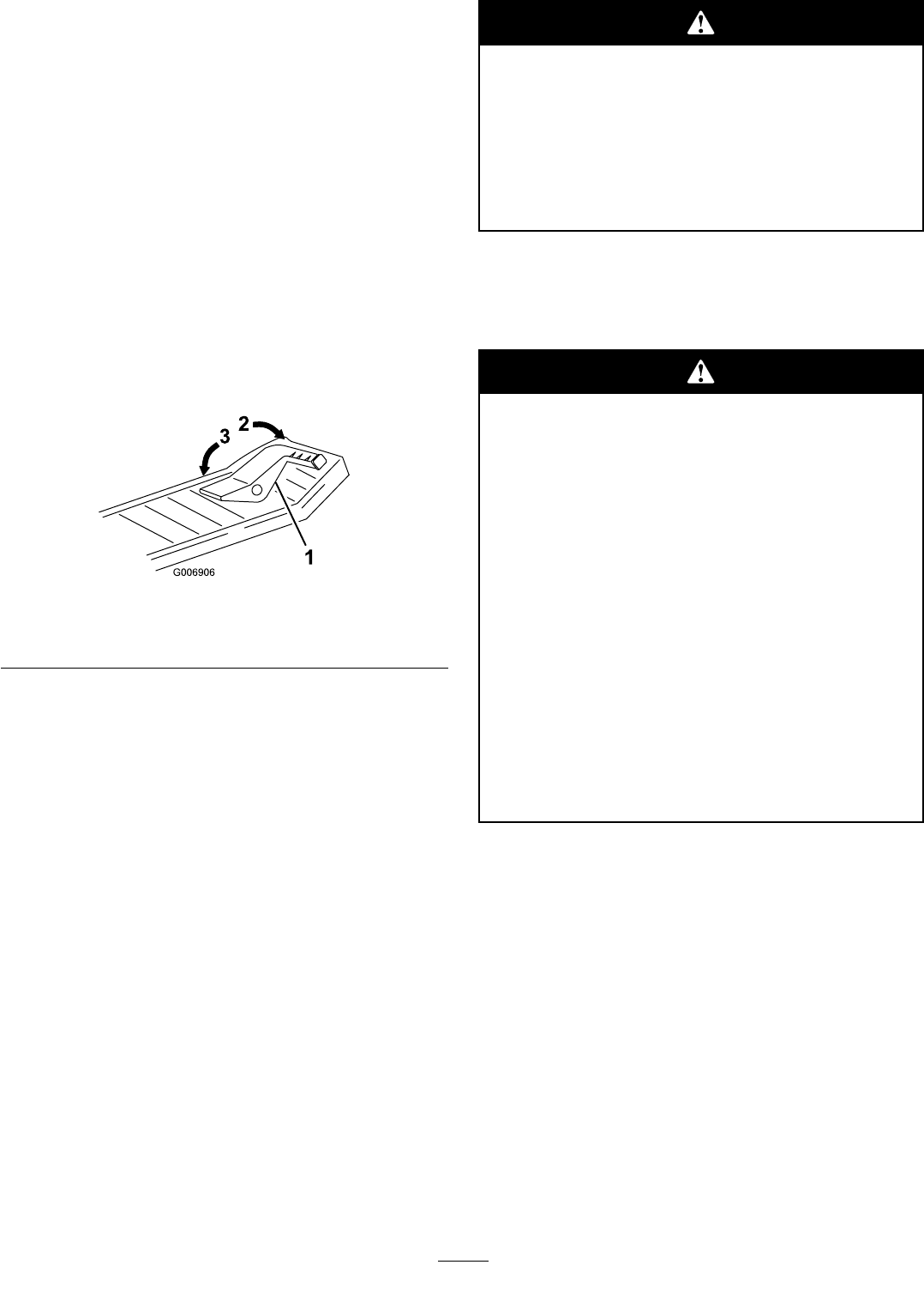
2.Liftthegrassdeectorandslidethetabsontop
ofthedischargecoverunderthegrassdeector
retainingrod.
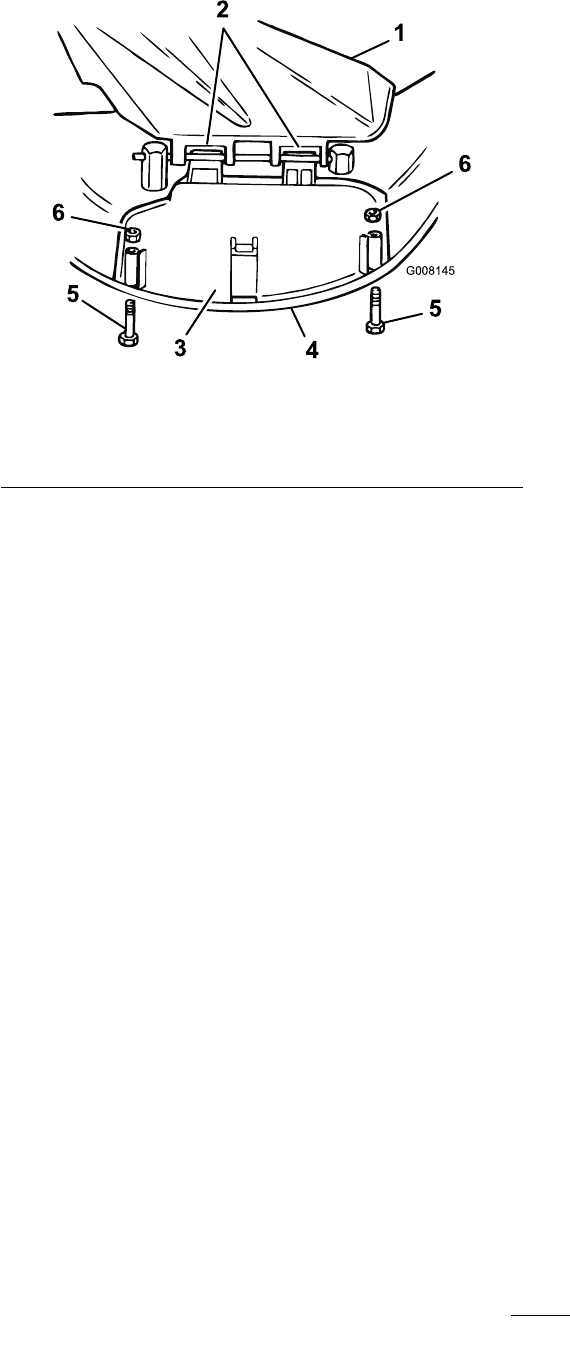
3.Rotatethedischargecoverdownovertheopening,
andontothelowerlipofthecutterdeck(Figure24).
G008145
1
2
34
55
6
6
Figure24
1.Grassdeector4.Lowerlip
2.Tabsunderrod5.Bolt
3.Dischargecover6.Nut
4.Securethedischargecovertothelowerlipofthe
cutterdeckwithboltsandnuts(Figure24).
Note:Donotovertightenthenuts,whichcould
distortthecoverandcausebladecontact.
5.Toconvertbacktoasidedischargecutterdeck,
removethedischargecoverandlowerthegrass
deectoroverthedischargeopening.
OperatingTips
•Forthebestperformance,operatetheengineatthe
maximumspeed.Thecutterdeckrequiresairto
thoroughlycutgrassclippings,sodonotsetthe
height-of-cuttooloworcompletelysurroundthe
cutterdeckinuncutgrass.Alwaysleaveonesideof
thecutterdeckfreefromuncutgrasstoallowthe
airtobedrawnintothecutterdeck.
•Cutthegrassslightlylongerthannormaltoensure
thatthecuttingheightofthecutterdeckdoes
notscalpanyunevenground.Whencuttinggrass
longerthan6inch(15cm)tall,cutthelawntwiceto
ensureanacceptableappearance.
•Itisbesttocutonlyabout1/3ofthegrassblade.
Donotcutmorethanthatunlessthegrassissparse
oritislatefallwhengrassgrowsmoreslowly.
•Alternatethemowingdirectiontokeepthegrass
standingstraight.Thisalsohelpsdisperseclippings
andenhancesdecompositionandfertilization.
•Grassgrowsatdifferentratesatdifferenttimesof
theseason.Tomaintainthesamecuttingheight,
whichisagoodpractice,mowmoreofteninearly
spring.Asthegrassgrowthrateslowsinmid
summer,mowlessfrequently.
•Toimprovethequalityofcut,useaslowerground
speed.Forbestoperationonaveragelawns,operate
theengineatfullthrottlewhilecontrollingthe
groundspeed.Youshouldoperatethetractor
between2to3.5mph(3.2to5.6km/h)while
mowing.
•Ifthegrassislongerthannormal,orifitcontains
ahighdegreeofmoisture,raisethecuttingheight
higherthanusual,cutthegrassatthatsetting,and
thencutthegrassagainatthelower,normalsetting.
•Ifyoumuststopthetractorwhilemowing,youmay
leaveaclumpofgrassclippingsonyourlawn.To
avoidthis,dothefollowing:
–Engagethebladeandmovetoapreviouslycut
area.
–Dispersetheclippingsevenlybyraisingthe
cutterdeck1or2height-of-cutsettingswhile
drivingforwardwiththebladeengaged.
•Usethewashoutporttocleanclippingsanddirt
fromtheundersideofthecutterdeckaftereachuse.
Ifgrassanddirtbuildupinsidethecutterdeck,the
cuttingqualitywilleventuallybecomeunsatisfactory.
•Maintainasharpbladethroughouttheseason.A
sharpbladecutsgrasscleanlywithouttearingor
shreddingthegrassblades.Tearingandshredding
thegrassturnsitbrownattheedges,whichslows
itsgrowthandincreasesthechanceofdisease.
Every30days,checkthebladeforsharpnessand
ledownanynicks.
23

Maintenance
Note:Determinetheleftandrightsidesofthemachinefromthenormaloperatingposition.
RecommendedMaintenanceSchedule(s)
MaintenanceService
IntervalMaintenanceProcedure
Aftertherst5hours•Changetheengineoil.
Beforeeachuseordaily
•Checktheengineoillevel.
•Checkthesafetysystem.
•Checktheoillevel.
•Checkthebatteryelectrolyte.
•Checktheparkingbrake.
•Servicetheblades.
•Washtheundersideofthecutterdeck.
Every25hours
•Greaseandlubricatethetractor.Moreoftenindustyordirtyconditions.
•Cleantheaircleanerfoamelement.
•Servicethesparkplug.
•Checkthetyrepressure.
Every50hours•Changetheengineoil.Changeitmoreoftenunderaheavyloadorinhigh
temperatures.
Every100hours
•Changetheoillter.
•Replacetheaircleanerpaperelement.
•Replacethesparkplug.
•Replacethefuellter.
•Servicethetransaxleuid.
•Cleanthecoolingsystem.
Beforestorage
•Drainthefueltank.
•Performallthemaintenanceprocedureslistedabove.
•Paintanychippedsurfaces.
•Checkthetyrepressure.
•Checkthesafetysystem.
•Checkthebrakes.
•Checkthesparkplug.
•Checkthebatteryelectrolyte.
•Chargethebatteryanddisconnectthecables.
•Checkthebelt(s)forwearandcracks.
Important:Refertoyourengineoperator’smanualforadditionalmaintenanceprocedures.
Ifyouleavethekeyintheignitionswitch,someonecouldaccidentlystarttheengineandseriously
injureyouorotherbystanders.
Removethekeyfromtheignitionanddisconnectthewirefromthesparkplugbeforeyoudoany
maintenance.Setthewireasidesothatitdoesnotaccidentallycontactthesparkplug.
24
Lubrication
GreasingandLubricatingthe
Tractor
ServiceInterval:Every25hours—Greaseandlubricate
thetractor.Moreoftenindustyor
dirtyconditions.
HowtoGreasetheTractor
1.Disengagethebladecontrol(PTO).
2.Settheparkingbrake.
3.Stoptheengine,removethekey,andwaitforall
movingpartstostopbeforeleavingtheoperating
position.
4.Cleanthegreasettingswitharag.
Note:Ensurethatyouscrapeanypaintoffthe
frontofthettings.
5.Connectagreaseguntoeachttingandpump
greaseintoit.
6.Wipeupanyexcessgrease.
WheretoAddGrease
Lubricatethefrontwheelsandsteeringspindlesuntil
greasebeginstooozeoutofthebearings(Figure25).
Figure25
EngineMaintenance
ServicingtheEngineOil
OilType:Detergentoil(APIserviceSF,SG,SH,SJ,or
higher)
CrankcaseCapacity:48oz.or1-1/2qt.(1400ccor1.4
l)whenthelterisnotchanged;56oz.or1-3/4qt.
(1700ccor1.7l)whenthelterischanged.
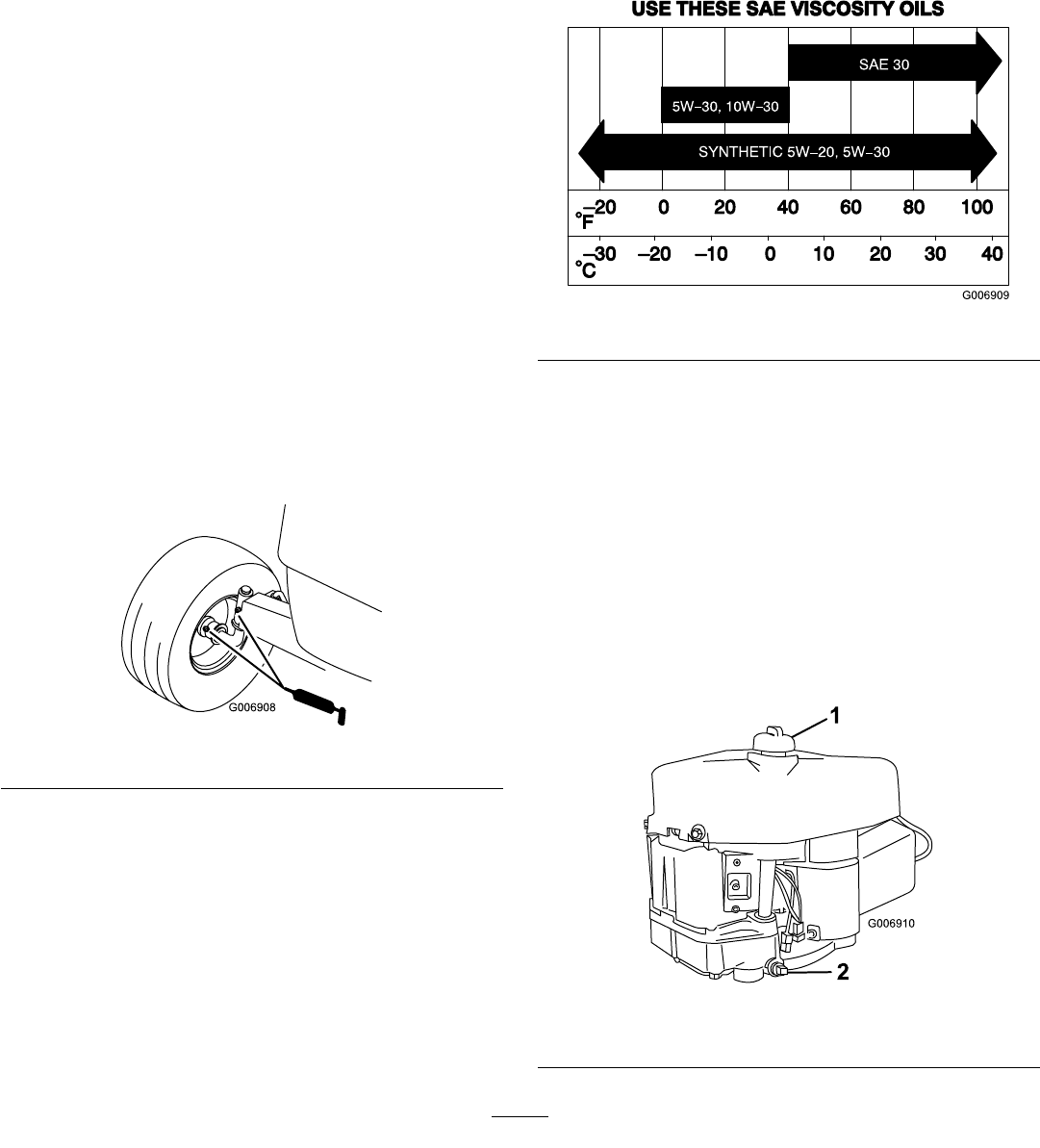
Viscosity:Seethetablebelow.
Figure26
CheckingtheOilLevel
ServiceInterval:Beforeeachuseordaily
1.Parkthetractoronalevelsurface.
2.Disengagethebladecontrol(PTO).
3.Settheparkingbrake.
4.Stoptheengine,waitforallmovingpartstostop,and
removethekeybeforeleavingtheoperatingposition.
5.Openthehood.
6.Cleanaroundtheoildipstick(Figure27)sothatdirt
cannotfallintothellholeanddamagetheengine.
Figure27
1.Oildipstick/llhole2.Oildrainplug
25
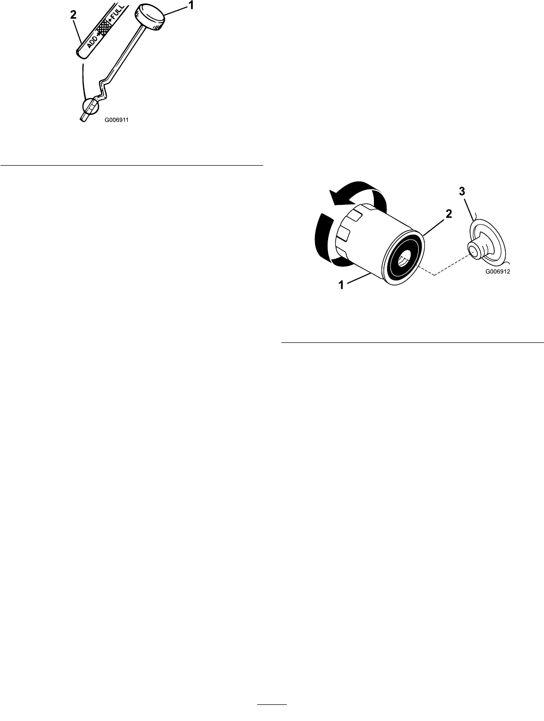
7.Unscrewtheoildipstickandwipethemetalend
clean(Figure28).
Figure28
1.Oildipstick2.Metalend
8.Screwtheoildipstickfullyontothellhole.
9.Unscrewthedipstickagainandlookatthemetal
end.Iftheoillevelislow,slowlypouronlyenough
oilintothellholetoraisetheleveltotheFullmark
onthedipstick.
Important:Donotoverllthecrankcasewith
oilandruntheengine;theenginedamagemay
result.
ChangingtheOil
ServiceInterval:Aftertherst5hours
Every50hoursChangeitmore
oftenunderaheavyloadorinhigh
temperatures.
1.Starttheengineandletitrunfor5minutes.
Note:Thiswarmstheoilsothatitwilldrainmore
easily.
2.Parkthetractorsothattheleftsideisslightlylower
thantherightsidetoensurethattheoildrains
completely.
3.Disengagethebladecontrol(PTO).
4.Settheparkingbrake.
5.Stoptheengine,waitforallmovingpartstostop,and
removethekeybeforeleavingtheoperatingposition.
6.Openthehood.
7.Placeadrainpanbelowtheoildrainplugand
removeit(Figure27).
8.Whentheoilhasdrainedcompletely,installtheoil
drainplug.
Note:Disposeoftheusedoilatacertiedrecycling
center.
9.Changetheoillter,ifnecessary.RefertoChanging
theOilFilter.
10.Slowlypourapproximately80%ofthespecied
amountofoilintothellhole(Figure27).Checkthe
oillevel;referto4and5ofCheckingtheOilLevel.
ChangingtheOilFilter
ServiceInterval:Every100hours
Note:Changetheoilltermorefrequentlywhenthe
operatingconditionsareextremelydustyorsandy.
1.Draintheoilfromtheengine;refertoChangingand
DrainingtheOil.
2.Removetheoldoillterandwipethelteradapter
(Figure29)gasketsurface.
Figure29
1.Oillter3.Filteradapter
2.Gasket
3.Applyathincoatofnewoiltotherubbergasketon
thenewoillter(Figure29).
4.Installthenewoilltertothelteradapter.
5.Turntheoillterclockwiseuntiltherubbergasket
contactsthelteradapter,thentightentheoillter
anadditional1/2to3/4turn(Figure29).
6.Slowlypourabout80%ofthespeciedamountof
oilintothellhole(Figure27).Checktheoillevel;
referto7and8ofCheckingtheOilLevel.
7.Closethehood.
ServicingtheAirCleaner
ServiceInterval:Every25hours—Cleantheaircleaner
foamelement.
Every100hours—Replacetheair
cleanerpaperelement.
Note:Servicetheaircleanermorefrequentlyifthe
operatingconditionsareextremelydustyorsandy.
RemovingtheFoamandPaper
Elements
1.Disengagethebladecontrol(PTO).
26
2.Settheparkingbrake.
3.Stoptheengine,waitforallmovingpartstostop,and
removethekeybeforeleavingtheoperatingposition.
4.Openthehood.
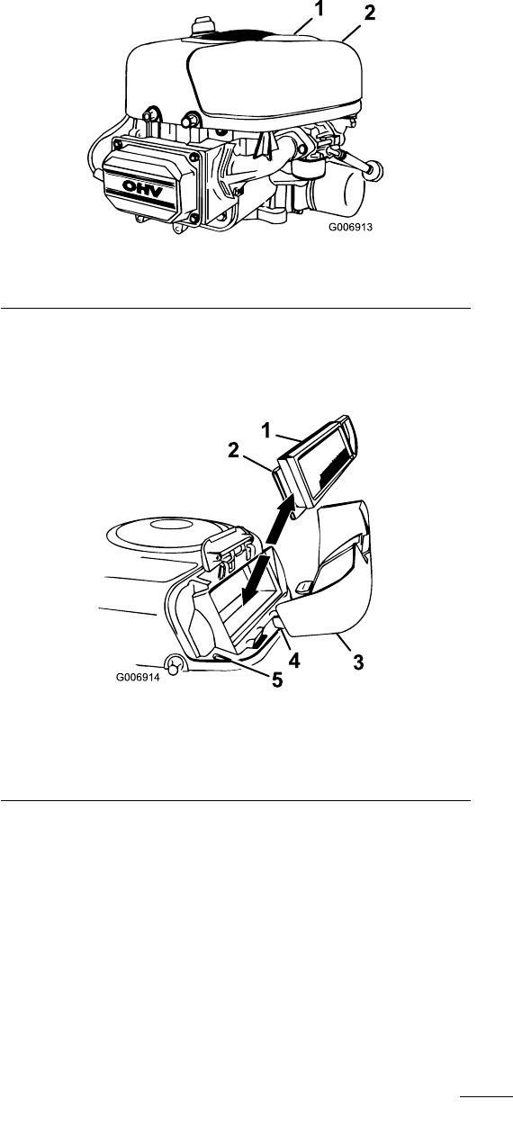
5.Cleanaroundtheaircleanertopreventdirtfrom
gettingintotheengineandcausingdamage.
6.Pullupontheaircleanercoverhandleandrotateit
towardtheengine(Figure30).
Figure30
1.Aircleanercover2.Aircleanercoverhandle
Note:Removetheaircleanercover.
7.Carefullyslidethepaperelementandthefoam
elementfromtheblowerhousing(Figure31).
Figure31
1.Paperelement4.Tab
2.Foamelement5.Slot
3.Aircleanercover
CleaningtheFoamandPaperElements
FoamElement:
1.Washthefoamelementinliquidsoapandwarm
water.Whentheelementisclean,rinseitthoroughly.
2.Drytheelementbysqueezingitinacleancloth.Do
notoiltheelement.
Important:Replacethefoamelementifitis
tornorworn.
PaperElement:
1.Lightlytaptheelementonaatsurfacetoremove
dustanddirt.
2.Carefullycleantherubbersealonthepaperelement
topreventdebrisfromenteringtheengine.
3.Inspecttheelementfortears,anoilylm,and
damagetotherubberseal.
Important:Nevercleanthepaperelement
withpressurizedairorliquidssuchassolvents,
petrol,orkerosene.Replacethepaperelementif
itisdamagedorcannotbecleanedthoroughly.
InstallingtheFoamandPaperElements
Important:Topreventenginedamage,always
operatetheenginewiththecompletefoamand
paperaircleanerassemblyinstalled.
1.Placethefoamelementandpaperelementintothe
blowerhousing.
Note:Makesurethattherubbersealisatagainst
theaircleanerbase.
2.Alignthetabsontheaircleanercoverwiththeslots
oftheblowerhousing(Figure31).
3.Hookthehandleontothecoverandpressdownon
thehandletolockthecoverinplace.
4.Closethehood.
ServicingtheSparkPlug
ServiceInterval:Every25hours—Servicethespark
plug.
Every100hours—Replacethespark
plug.
UseaChampionQC12YCorequivalentsparkplug.
Makesurethattheairgapbetweenthecenterandside
electrodesis0.030inch(0.76mm)beforeinstallingthe
sparkplug.Useasparkplugwrenchforremovingand
installingthesparkplugandagappingtool/feelergauge
tocheckandadjusttheairgap.
RemovingtheSparkPlug
1.Disengagethebladecontrol(PTO).
2.Settheparkingbrake.
3.Stoptheengine,waitforallmovingpartstostop,and
removethekeybeforeleavingtheoperatingposition.
4.Openthehood.
5.Disconnectthewirefromthesparkplug(Figure32).
27
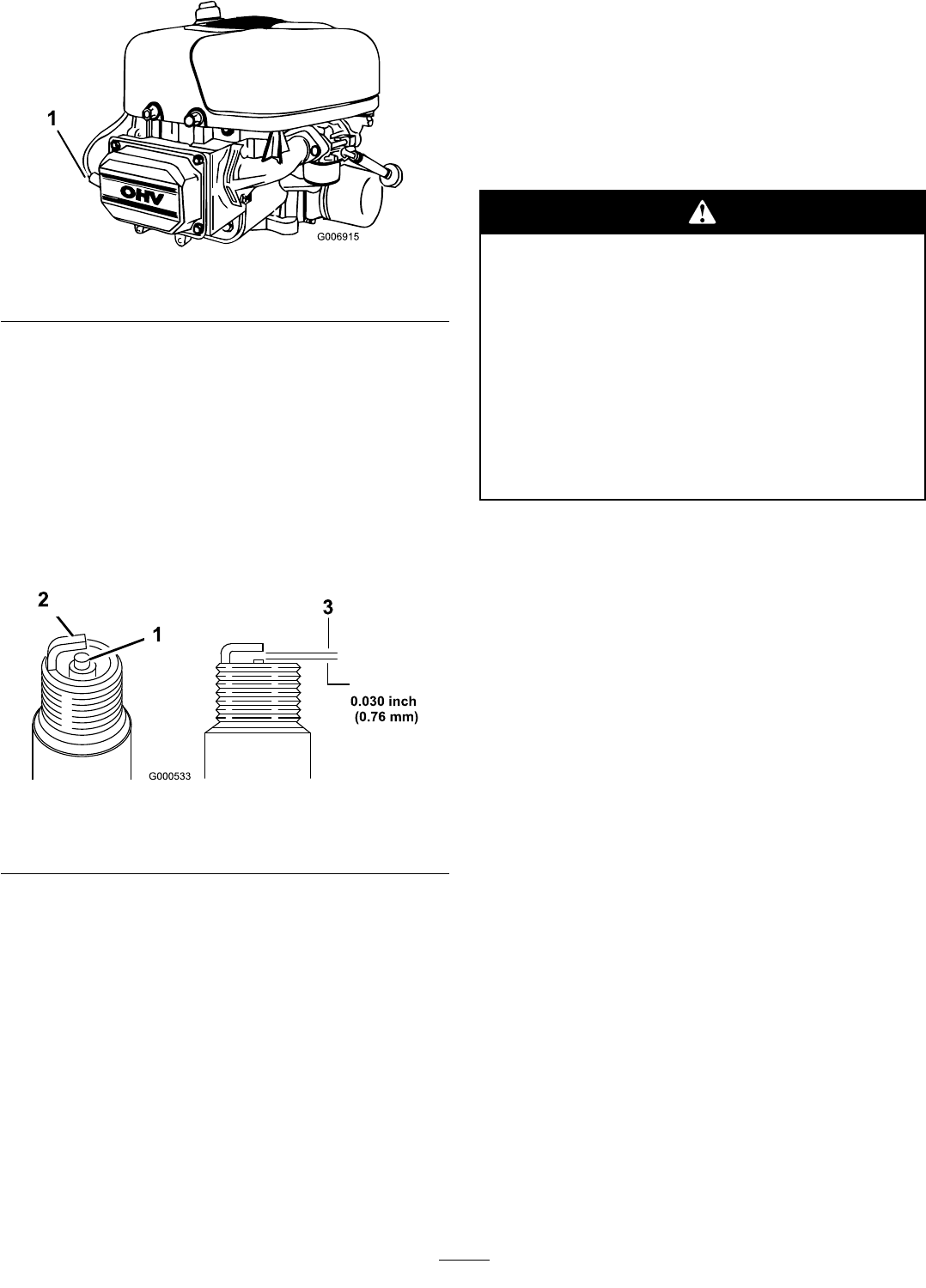
Figure32
1.Spark-plugwire
6.Cleanaroundthesparkplugtopreventdirtfrom
fallingintotheengineandpotentiallycausing
damage.
7.Removethesparkplugandmetalwasher.
CheckingtheSparkPlug
1.Lookatthecenterofthesparkplug(Figure33).
Ifyouseelightbrownorgrayontheinsulator,the
engineisoperatingproperly.Ablackcoatingonthe
insulatorusuallymeanstheaircleanerisdirty.
Figure33
1.Centerelectrodeinsulator3.Airgap(nottoscale)
2.Sideelectrode
Important:Nevercleanthesparkplug.Always
replacethesparkplugwhenithasablack
coating,wornelectrodes,anoilylm,orcracks.
2.Checkthegapbetweenthecenterandsideelectrodes
(Figure33).Bendthesideelectrodeifthegapisnot
correct.
InstallingtheSparkPlug
1.Installthesparkplugandmetalwasher.
Note:Ensurethattheairgapissetcorrectly.
2.Tightenthesparkplugto15ft-lb(20N⋅m).
3.Connectthewiretothesparkplug(Figure32).
4.Closethehood.
FuelSystem
Maintenance
DrainingtheFuelTank
ServiceInterval:Beforestorage
Incertainconditions,petrolisextremely
ammableandhighlyexplosive.Areor
explosionfrompetrolcanburnyouandothers
andcandamageproperty.
•Drainpetrolfromthefueltankwhenthe
engineiscold.Dothisoutdoorsinanopen
area.Wipeupanypetrolthatspills.
•Neversmokewhendrainingpetrol,andstay
awayfromanopenameorwhereaspark
mayignitethepetrolfumes.
1.Parkthetractorsothattheleftfrontsideisslightly
lowerthantherightsidetoensurethatthefueltank
drainscompletely.
2.Disengagethebladecontrol(PTO).
3.Settheparkingbrake.
4.Stoptheengine,waitforallmovingpartstostop,and
removethekeybeforeleavingtheoperatingposition.
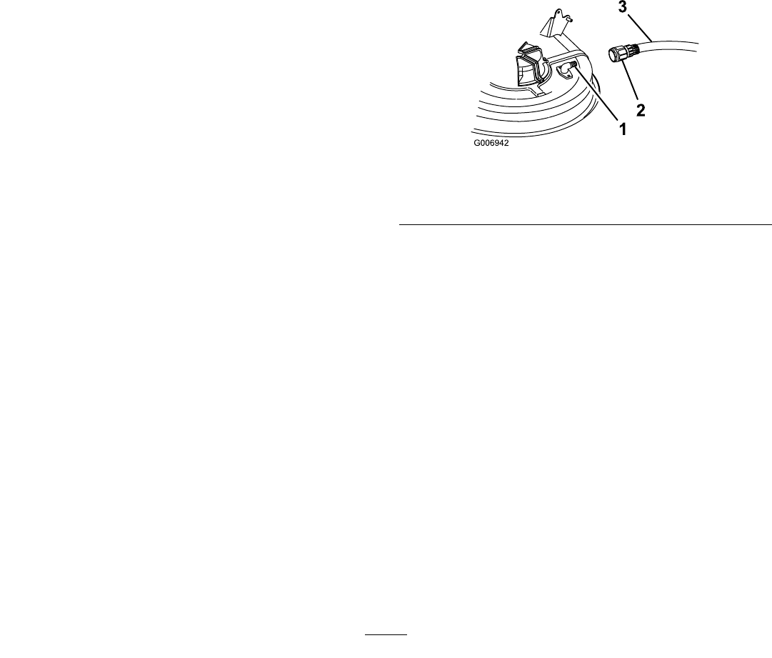
5.Openthehoodandlocatethefuellter(Figure34).
28
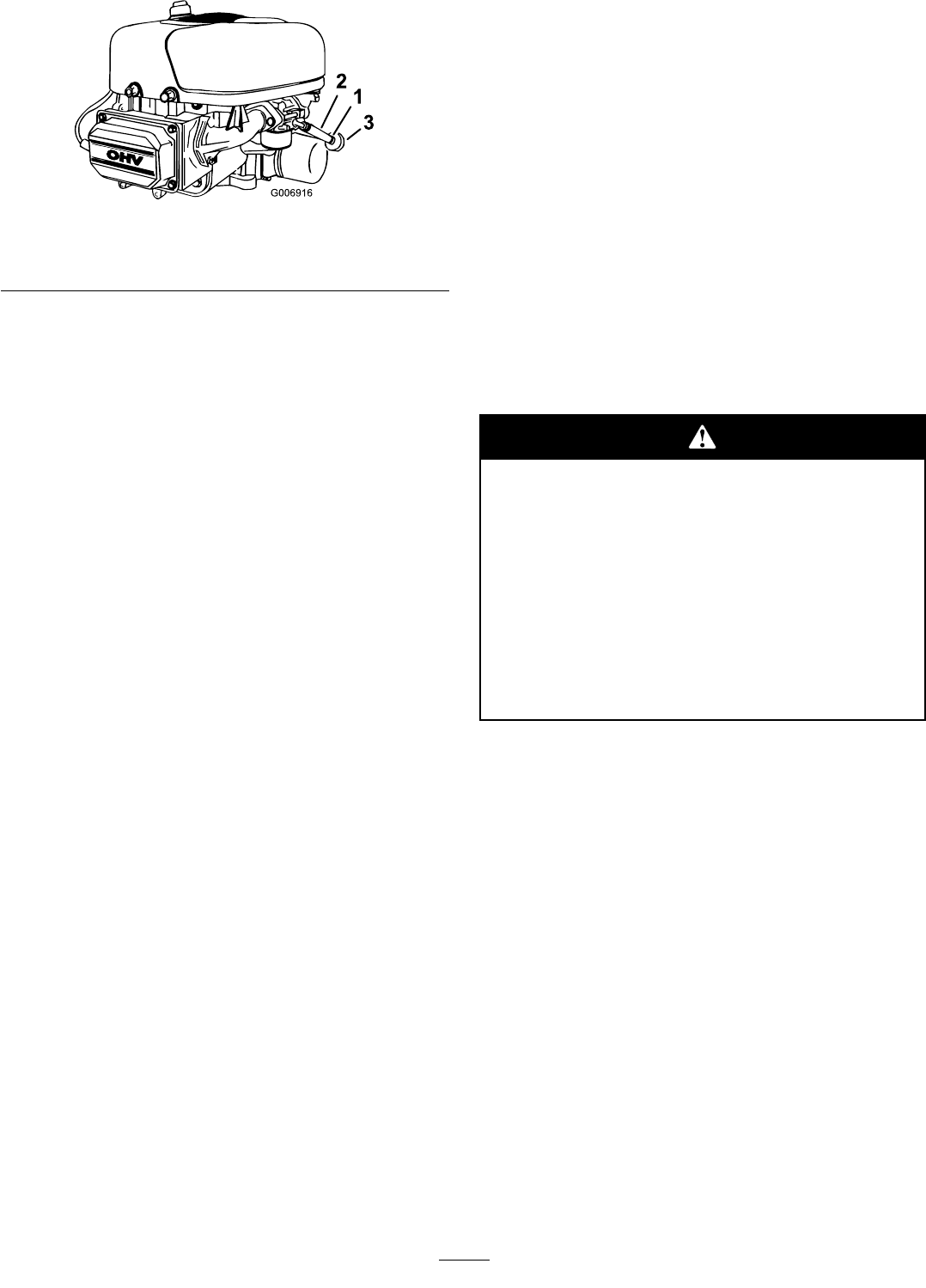
Figure34
1.Hoseclamp3.Fuellter
2.Fuelline
6.Squeezetheendsofthehoseclamptogether
andslideitupthefuellinetowardthefueltank
(Figure34).
7.Pullthefuellineoffofthefuellter(Figure34)and
allowpetroltodrainintoafuelcontaineroradrain
pan.
Note:Nowisthebesttimetoinstallanewfuel
lterbecausethefueltankisempty.
8.Installthefuellineontothefuellter.
9.Slidethehoseclampclosetothefuelltertosecure
boththefuellineandthefuellter.
ReplacingtheFuelFilter
ServiceInterval:Every100hours—Replacethefuel
lter.
Thebesttimetoreplacethefuellter(Figure34)is
whenthefueltankisempty.Neverinstalladirtyfuel
lterafterithasbeenremovedfromthefuelline.
1.Disengagethebladecontrol(PTO)andsetthe
parkingbrake.
2.Stoptheengine,waitforallmovingpartstostop,and
removethekeybeforeleavingtheoperatingposition.
3.Openthehood.
4.Squeezetheendsofthehoseclampstogetherand
slidethemawayfromthefuellter(Figure34).
5.Removethefuellterfromthefuellines.
6.Installanewfuellterandmovethehoseclamps
closetothefuellter.
7.Closethehood.
ElectricalSystem
Maintenance
ServicingtheBattery
Alwayskeepthebatterycleanandfullycharged.Use
apapertoweltocleanthebatteryandbatterybox.If
thebatteryterminalsarecorroded,cleanthemwitha
solutionof4partswaterand1partbakingsoda.Apply
alightcoatingofgreasetothebatteryterminalsto
preventcorrosion.
Batteryvoltageandamperage:12volts,155
cold-crankingamps
RemovingtheBattery
Batteryterminalsormetaltoolscouldshort
againstmetaltractorcomponents,causing
sparks.Sparkscancausethebatterygassesto
explode,resultinginpersonalinjury.
•Whenremovingorinstallingthebattery,do
notallowthebatteryterminalstotouchany
metalpartsofthetractor.
•Donotallowmetaltoolstoshortbetween
thebatteryterminalsandmetalpartsofthe
tractor.
1.Disengagethebladecontrol(PTO)andsetthe
parkingbrake.
2.Stoptheengine,removethekey,andwaitforall
movingpartstostopbeforeleavingtheoperating
position.
3.Tiptheseatforwardtoseethebattery.
4.Disconnectthenegative(black)groundcablefrom
thebatterypost(Figure35).
29
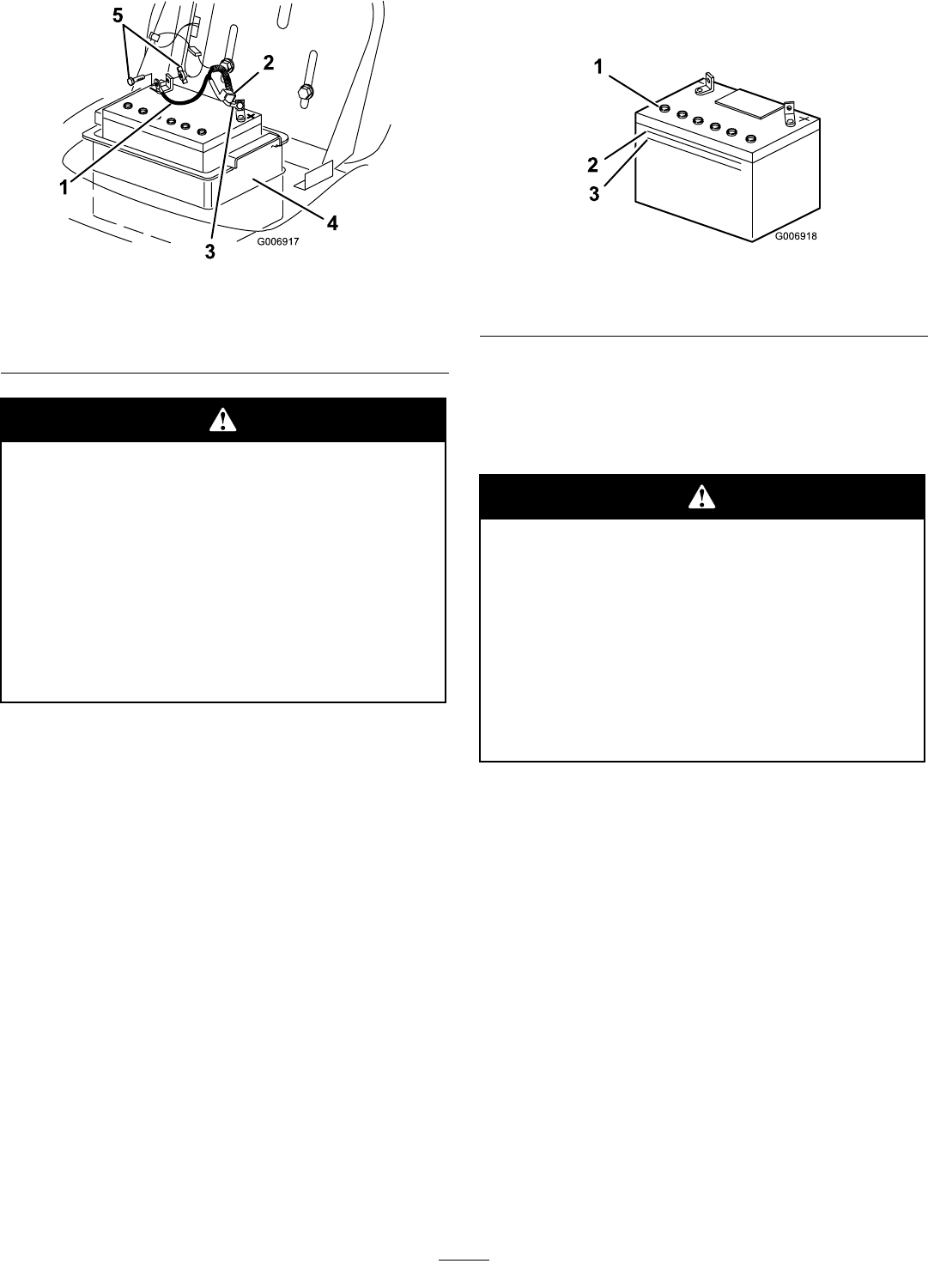
Figure35
1.Negativecable(black)4.Batterybox
2.Rubbercover5.Boltandwingnut
3.Positivecable(red)
Incorrectlyroutingthebatterycablecould
damagethetractorandcables,causingsparks.
Sparkscancausethebatterygassestoexplode,
resultinginpersonalinjury.
•Always
disconnect
thenegative(black)
batterycablebeforedisconnectingthe
positive(red)cable.
•Always
connect
thepositive(red)battery
cablebeforeconnectingthenegative(black)
cable.
5.Slidetherubbercoverupthepositive(red)cable.
Disconnectthepositive(red)cablefromthebattery
post(Figure35).
6.Removethebatteryboxandbatteryfromthechassis
(Figure35).
InstallingtheBattery
1.Putthebatteryintothebatteryboxandinstallitinto
thechassis(Figure35).
2.Usingtheboltandwingnut,connectthepositive
(red)cabletothepositive(+)batterypost(Figure35).
3.Slidetherubbercoveroverthebatterypost.
4.Usingtheboltandthewingnut,connectthe
negative(black)cabletothenegative(–)batterypost
(Figure35).
CheckingtheElectrolyteLevel
ServiceInterval:Beforeeachuseordaily
1.Tiptheseatforwardtoseethebattery.
2.Lookatthesideofthebattery.Theelectrolytemust
beuptotheUpperline(Figure36).
Figure36
1.Ventcaps3.Lowerline
2.Upperline
Note:Donotallowtheelectrolytetofallbelowthe
Lowerline(Figure36).
3.Iftheelectrolyteislow,addtherequiredamountof
distilledwater;refertoAddingWatertotheBattery.
Batteryelectrolytecontainssulfuricacid,a
deadlypoisonthatcanseverelyburnyouand
others.
•Donotdrinkelectrolyteandavoidcontact
withskin,eyes,orclothing.Wearsafety
glassestoshieldyoureyesandrubbergloves
toprotectyourhands.
•Fillthebatterywherecleanwaterisalways
availableforushingtheskin.
AddingWatertotheBattery
Thebesttimetoadddistilledwatertothebatteryisjust
beforeyouoperatethetractor.Thisletsthewatermix
thoroughlywiththeelectrolytesolution.
1.Removethebatteryfromthetractor;referto
RemovingtheBattery.
2.Cleanthetopofthebatterywithapapertowel.
Important:Neverllthebatterywithdistilled
waterwhilethebatteryisinstalledinthetractor.
Youcouldspillelectrolyteonotherpartsand
causecorrosion.
3.Removetheventcapsfromthebattery(Figure36).
4.Slowlypourdistilledwaterintoeachbatterycell
untiltheelectrolytelevelisuptotheUpperline
(Figure36)onthebatterycase.
30
Important:Donotoverllthebatterybecause
electrolyte(sulfuricacid)cancausesevere
corrosionanddamagetothechassis.
5.Wait5to10minutesafterllingthebatterycells.
Adddistilledwater,ifnecessary,untiltheelectrolyte
levelisuptotheUpperline(Figure36)onthe
batterycase.
6.Installthebatteryventcaps.
ChargingtheBattery
Chargingthebatteryproducesgassesthatcan
explode.
Neversmokenearthebattery.Keepsparksand
amesawayfrombattery.
Important:Alwayskeepthebatteryfullycharged
(1.260specicgravity),especiallywhenthe
temperatureisbelow32°F(0°C)topreventbattery
damage.
1.Removethebatteryfromthechassis;referto
RemovingtheBattery.
2.Checktheelectrolytelevel;refertoCheckingthe
ElectrolyteLevel.
3.Makesurethattheventcapsareinstalledinthe
battery,andchargeitfor1hourat25to30amps
or6hoursat4to6amps.Donotoverchargethe
battery.
4.Whenthebatteryisfullycharged,unplugthecharger
fromtheelectricaloutlet.
5.Disconnectthechargerleadsfromthebatteryposts
(Figure37).
Figure37
1.Positivebatterypost3.Red(+)chargerlead
2.Negativebatterypost4.Black(–)chargerlead
6.Installthebatteryinthetractorandconnectthe
batterycables;refertoInstallingtheBattery.
Note:Donotrunthetractorwiththebattery
disconnected;electricaldamagemayoccur.
ServicingtheFuse
Theelectricalsystemisprotectedby10amp,blade-type
fuses.
1.Pulluponthefuse(Figure38)toremoveitfrom
thesocket.
Figure38
1.Fuse2.Socket
2.Insertthefuseintosocketandpushdownonthe
fusetoinstallit.
ServicingtheHeadlights
Theheadlightsusean1156,automotive-typebulb.
RemovingtheBulb
1.Openthehood.
2.Disconnectthewireconnectorsfrombothofthe
bulbholderterminals.
3.Rotatethebulbholder1/4turncounterclockwise
andremoveitfromthereector(Figure39).
31
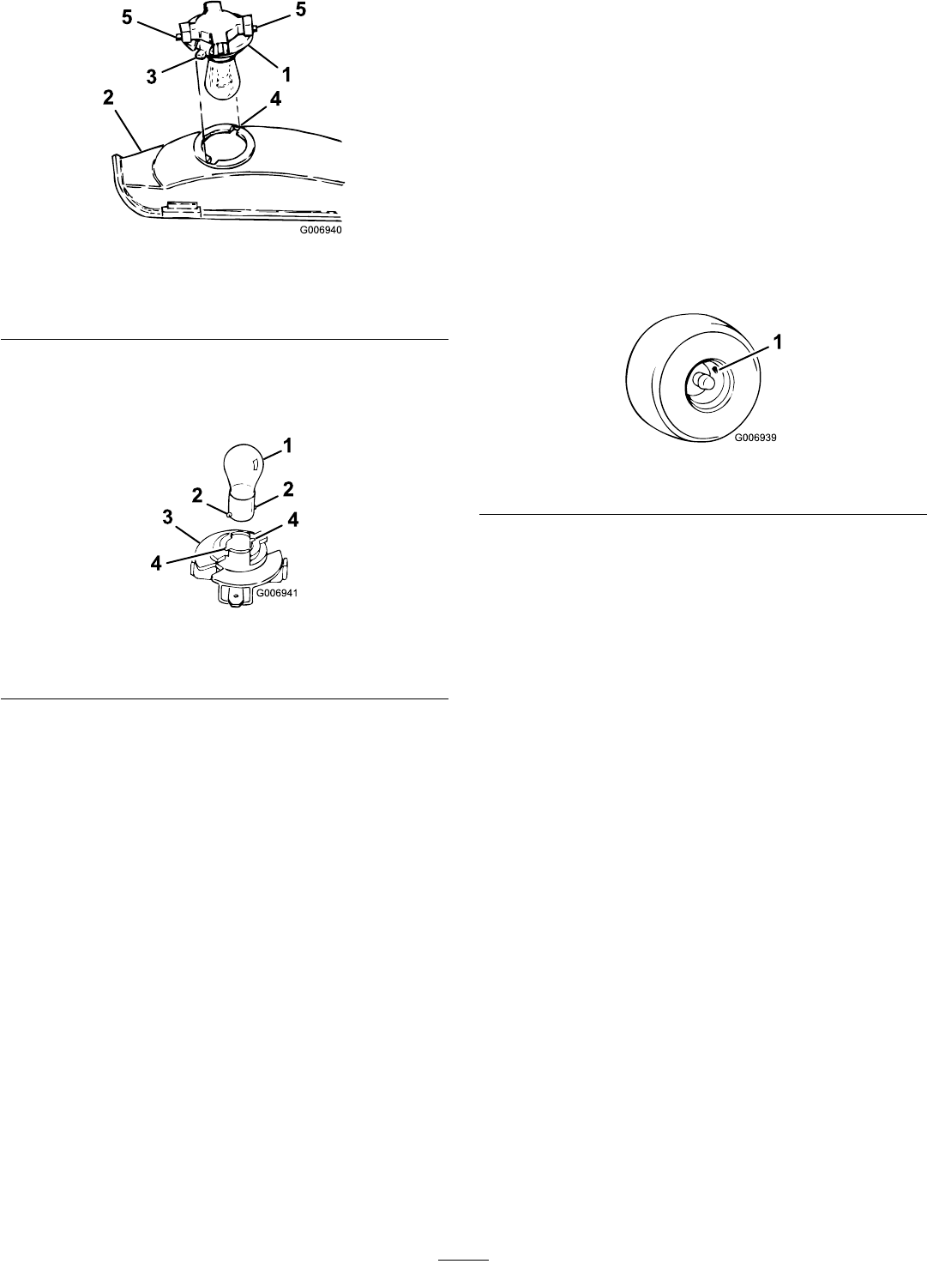
Figure39
1.Bulbholder4.Slots
2.Reector5.Terminals
3.Tabs
4.Insertandrotatethebulbcounterclockwiseuntilit
stops(approx.1/4turn),andremovethebulbfrom
thebulbholder(Figure40).
Figure40
1.Bulb3.Bulbholder
2.Metalpins4.Slots
InstallingtheBulb
1.Alignthemetalpinsonthesideofthebulbbase
withtheslotsinthebulbholder.
2.Insertthebaseintotheholder(Figure40).
3.Pushandrotatethebulbclockwiseuntilitstops.
4.Alignthetabsonthebulbholder(Figure39)with
theslotsinthereector,insertthebulbholderinto
thereector,androtateit1/4turnclockwiseuntil
itstops.
5.Connectthewireconnectorstotheterminalsonthe
bulbholder.
DriveSystem
Maintenance
CheckingtheTyrePressure
ServiceInterval:Every25hours
Maintaintheairpressureinthefrontandreartyresat
20psi(138kPa).Checkthepressureatthevalvestem
(Figure41)afterevery25operatinghoursoryearly,
whicheveroccursrst.Checkthetyreswhentheyare
coldtogetthemostaccuratepressurereading.
Figure41
1.Valvestem
ServicingtheTransaxleFluid
ServiceInterval:Every100hours—Servicethe
transaxleuid.
Alwayskeeptheuidlevelatthefulllevelwhenthe
transaxleiscold.
Note:Thetransaxleisfactorysealedanddoesnot
requireoilchanges.
FluidType:SAE20W-50engineoil(APIservice
SH/CDisrecommended)
CheckingtheFluidLevel
1.Parkthetractoronalevelsurface.
2.Disengagethebladecontrol(PTO)andsetthe
parkingbrake.
3.Stoptheengine,removethekey,andwaitforall
movingpartstostopbeforeleavingtheoperating
position.
4.Cleanaroundthellplug(Figure42)sothatdirt
cannotfallintothereservoirifyouneedtoadduid.
32
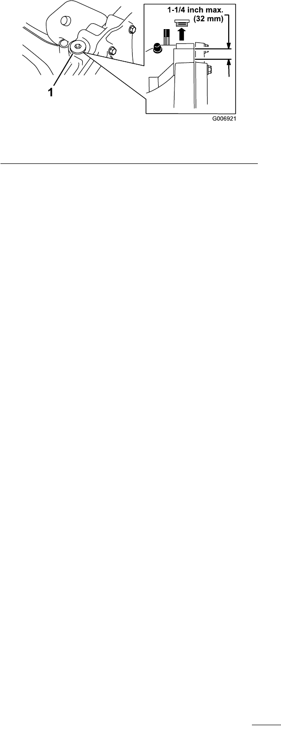
Figure42
1.Fillplug
5.Removethellplugandchecktheuidlevel.
Note:Thelevelshouldbeamaximumof1-1/4inch
(32mm)belowthetopofthellport(Figure42).
Adduidifnecessary.
6.Installthellplug.
CoolingSystem
Maintenance
CleaningtheCoolingSystem
ServiceInterval:Every100hours
Useadrybrushtocleangrassandaccumulateddebris
fromtheenginedaily.
Important:Topreventcontaminatingthefuel
system,donotusewatertocleantheengine.
33
BrakeMaintenance
ServicingtheParkingBrake
ServiceInterval:Beforeeachuseordaily
Theparkingbrakeisontherightsideoftherearaxle,
insidethereartyre(Figure43).Iftheparkingbrakedoes
notholdsecurely,adjustit.
Figure43
1.Brakearmspring2.Brakeadjustingnut
CheckingtheParkingBrake
1.Parkthetractoronalevelsurface.
2.Disengagethebladecontrol(PTO)andsetthe
parkingbrake.
3.Stoptheengine,removethekey,andwaitforall
movingpartstostopbeforeleavingtheoperating
position.
4.MovethedrivecontrolwiretothePushposition;
refertoPushingtheTractorManually.
5.Iftherearwheelslockandskidwhenyoupush
thetractorforward,youdonotneedtoadjustthe
parkingbrake.Adjusttheparkingbrakeifthewheels
turnanddonotlock;refertoAdjustingtheParking
Brake.
AdjustingtheParkingBrake
1.Checktheparkingbrakebeforeyouadjustit;referto
CheckingtheBrake.
2.Removethebrakearmspring(Figure43).
3.Removethecotterpinthatsecuresthebrake
adjustingnutandslightlyloosenthenut(Figure43).
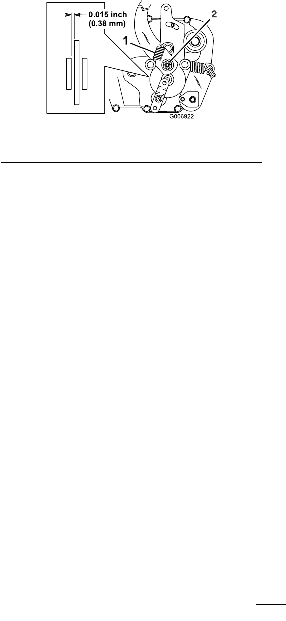
4.Inserta0.015inch(0.38mm)feelergaugebetween
thebrakediscandbrakepuck(Figure43).
5.Tightenthenutuntilyoufeelaslightresistanceon
thefeelergaugewhenyouslideitinandout.
6.Installanewcotterpinandattachthebrakearm
spring.
7.Checktheparkingbrakeoperationagain;referto
CheckingtheParkingBrake.
Important:Withtheparkingbrakereleased,the
rearwheelsmustrotatefreelywhenyoupushthe
tractor.Ifyoucannotachievethe.015inch(0.38
mm)clearanceandfreewheelrotation,contact
anAuthorizedServiceDealerimmediately.
34
BeltMaintenance
ReplacingtheBladeDriveBelt
RemovingtheBladeDriveBelt
1.Removethecutterdeck;refertoRemovingthe
CutterDeck.
2.Removethepulleycovermountingscrewsandpulley
coversfrombothbladepulleys(Figure44).
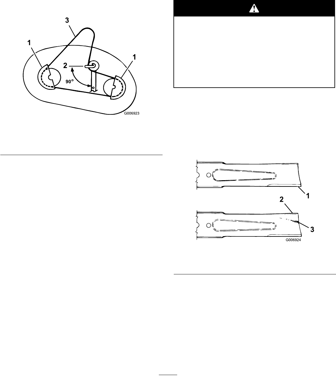
Figure44
1.Pulleycover3.cutterdeckbelt
2.Idlerpulleybeltguide
position
3.Loosen,butdonotremove,theboltandnutthat
securestheidlerpulleyandthebeltguide(Figure44).
4.Removethebladedrivebeltfromthepulleys.
InstallingtheBladeDriveBelt
1.Installthenewbladedrivebeltaroundtheblade
pulleysandunderthebeltguideontheidlerpulley.
2.Positiontheidlerpulleybeltguidesothatitpoints
towardtheleft,90°totheidlerarm(Figure44).
3.Tightenthemountingboltandthelocknutthat
securetheidlerpulleyandthebeltguide.
4.Installtheleftandrightpulleycoverswiththe
mountingscrews(Figure44).
5.Installthecutterdeck;refertoInstallingtheCutter
Deck.
CutterDeckMaintenance
ServicingtheBlades
ServiceInterval:Beforeeachuseordaily
Toensureasuperiorqualityofcut,keeptheblades
sharp.Forconvenientsharpeningandreplacement,
keepextrablades.
Awornordamagedbladecanbreakandapiece
ofthebladecouldbethrownintotheoperator’s
orbystander’sarea,resultinginseriouspersonal
injuryordeath.
•Inspectthebladeperiodicallyforwearor
damage.
•Replaceawornordamagedblade.
InspectingtheBlades
1.Removethecutterdeck;refertoRemovingthe
CutterDeck.
2.Inspectthecuttingedges(Figure45).Iftheedges
arenotsharporhavenicks,removethebladesand
sharpenthem;refertoSharpeningtheBlades.
Figure45
1.Cuttingedge3.Wear/slotforming
2.Curvedarea
3.Inspecttheblades,especiallythecurvedarea
(Figure45).Ifyounoticeanydamage,wear,oraslot
forminginthisarea(Figure45),immediatelyinstalla
newblade.
RemovingtheBlades
1.Removethecutterdeck;refertoRemovingthe
CutterDeck.
2.Carefullytipthecutterdeckover.
35
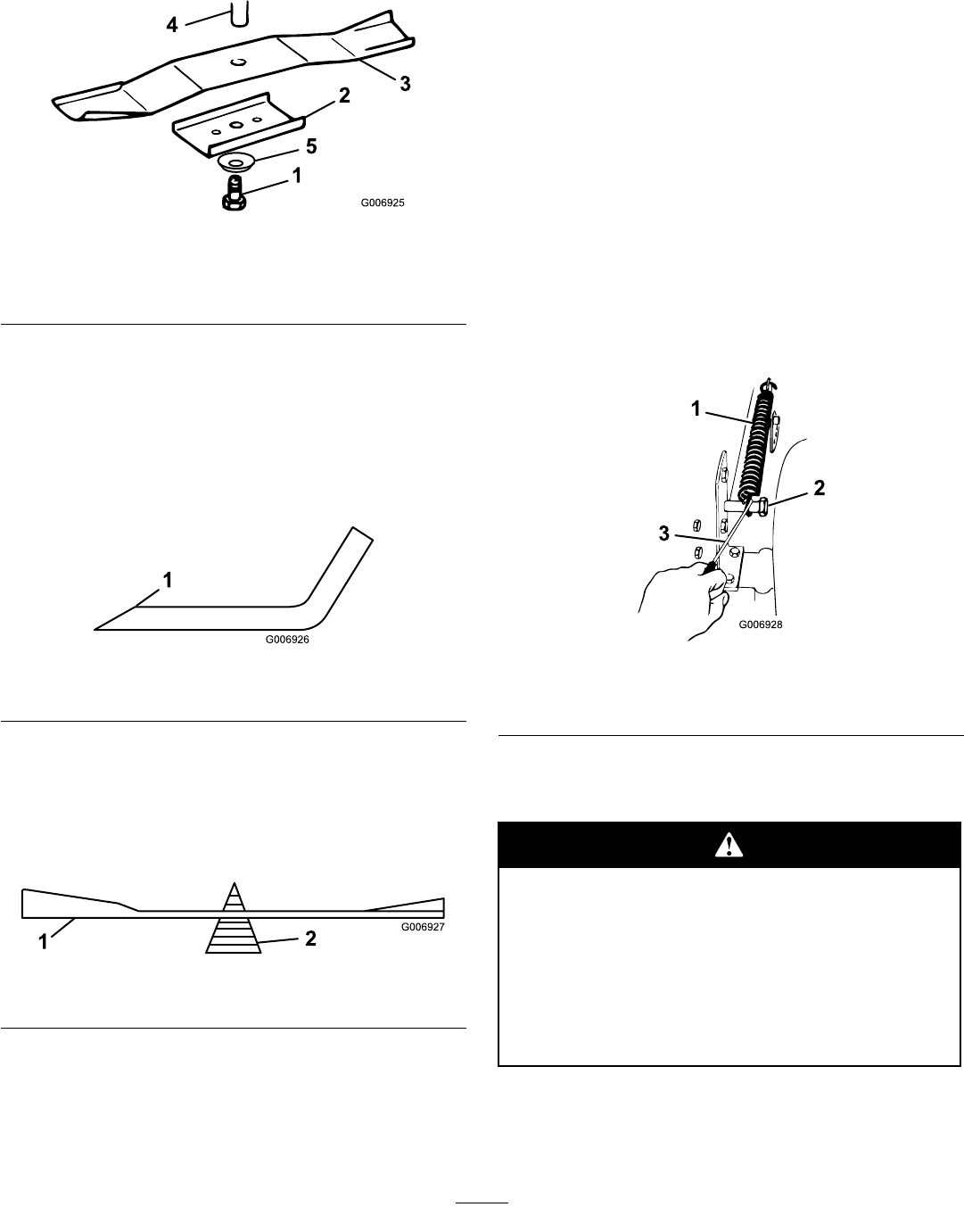
3.Removethebolt(5/8inchwrench),curvedwasher,
retainer,andblade(Figure46).Useablockofwood
asawedgebetweenthebladeandthecutterdeckto
lockthebladewhenyouareremovingthebolt.
Figure46
1.Bolt4.Spindle
2.Retainer5.Curvedwasher
3.Blade
4.Inspectallparts;replaceanypartsthataredamaged.
SharpeningtheBlades
1.Usealetosharpenthecuttingedgeatbothendsof
eachblade(Figure47).Maintaintheoriginalangle.
Thebladeretainsitsbalanceifyouremovethesame
amountofmaterialfrombothcuttingedges.
Figure47
1.Sharpenatoriginalangle
2.Checkthebalanceofeachbladebyputtingiton
abladebalancer(Figure48).Ifthebladestaysina
horizontalposition,thebladeisbalancedandcanbe
used.Ifthebladeisnotbalanced,lesomemetal
offofthebacksideoftheblade.Repeatthisstep
untilthebladeisbalanced.
Figure48
1.Blade2.Balancer
InstallingtheBlades
1.Installeachblade,bladeretainer,curvedwasher
(cuppedsidetowardblade),andthebladebolt
(Figure46).
Important:Thecurvedpartoftheblademust
bepointingtowardtheinsideofthecutterdeck
toensurepropercutting.
2.Tightenthebladeboltto45to60ft-lb(61to81
N⋅m).
RemovingtheCutterDeck
1.Parkthetractoronalevelsurface.
2.Disengagethebladecontrol(PTO)andsetthe
parkingbrake.
3.Stoptheengine,removethekey,andwaitforall
movingpartstostopbeforeleavingtheoperating
position.
4.Movetheheight-of-cutleverintothe“D”notch.
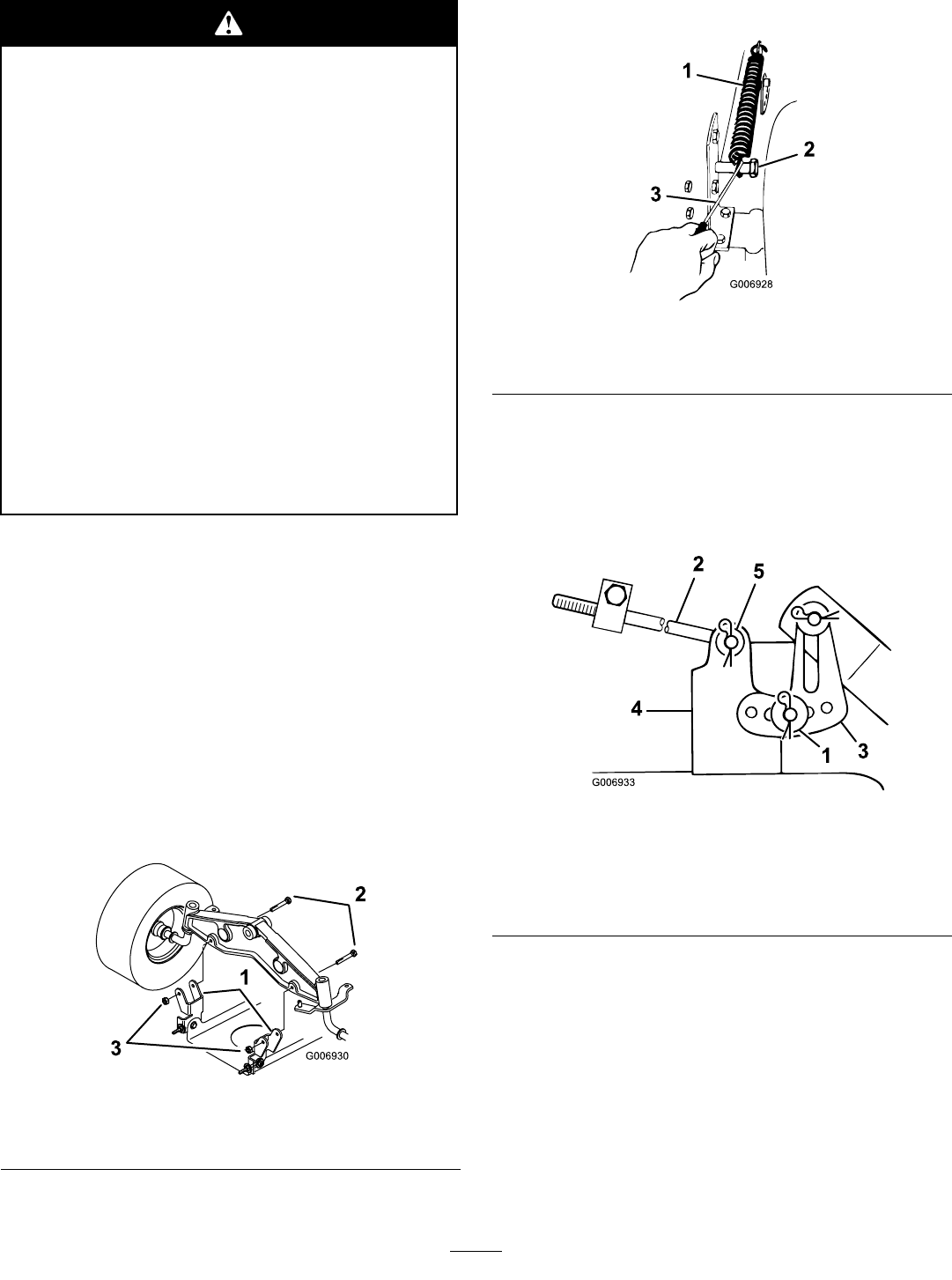
5.Removetheheight-of-cutliftassistspringfromthe
retainingbolt(Figure49).Thespringisbetweenthe
frameandtherightrearwheel.
Figure49
1.Spring3.Springtool
2.Bolt
Note:Usethespringtoolprovidedwiththe
machine.
Whenyouremovethecutterdeck,the
spring-tensionedheight-of-cutlevercould
suddenlyreleaseandinjureyouorsomeone
else.
Movetheheight-of-cutlevertothe“D”position
andremovetheheight-of-cutassistspringto
releasethespringtension.
6.Movetheheight-of-cutleverintothe“A”notch.
7.Unhookthespringontheidlerpulleyarmfromthe
bracketonthecutterdeck(Figure50).
36
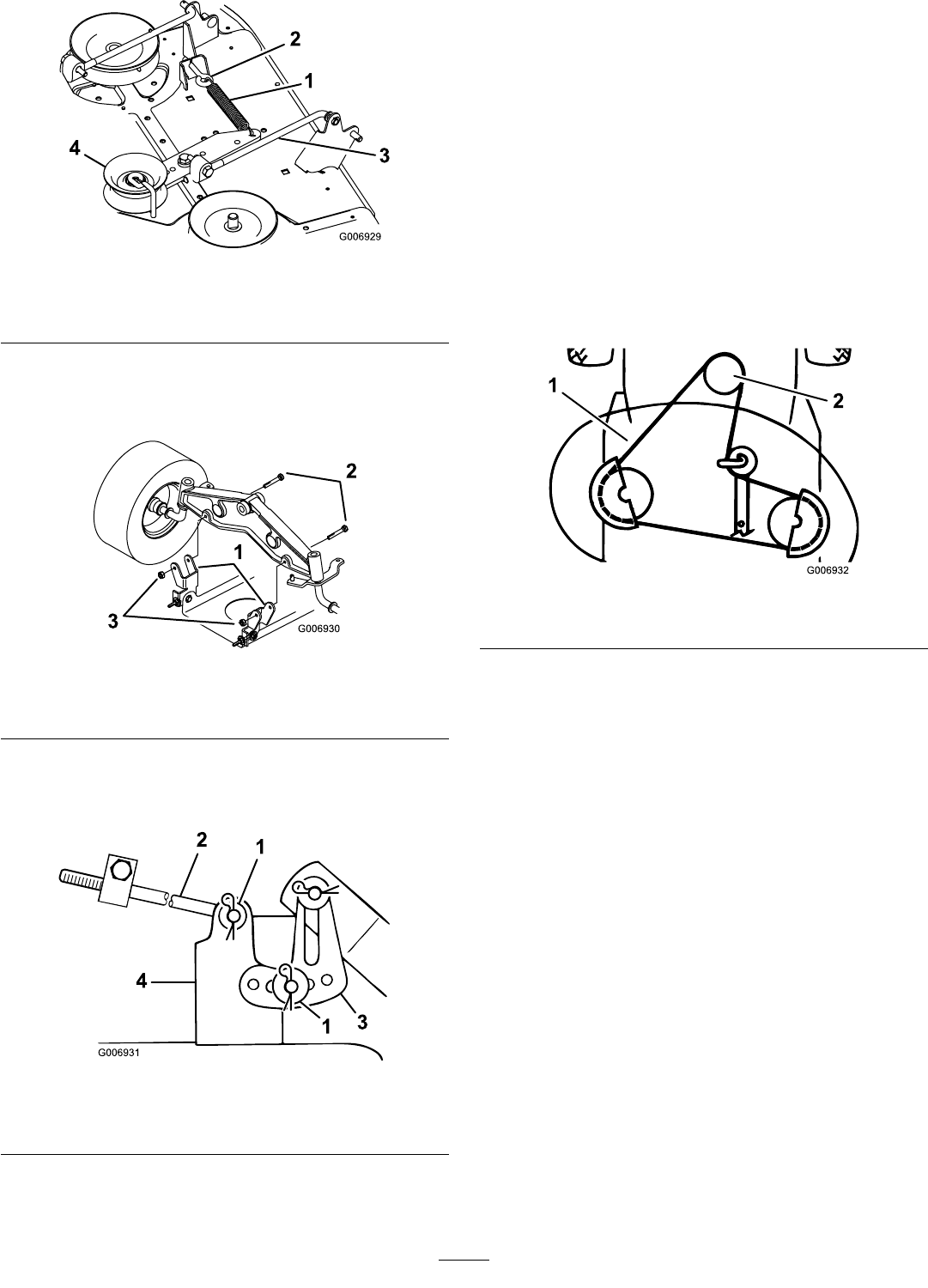
Figure50
1.Idlerspring3.Idlerarm
2.Eye-bolt4.Idlerpulley
8.Removetheboltsandlocknutsandpullthetwo
cutterdeckpivotmountbracketsdownfromthe
frontaxle(Figure51).
Figure51
1.Pivotmountbracket3.Locknut
2.Bolt(5/16x2-1/2inch)
9.Removethehairpincotterandwasherfromtheend
ofthelongrod(Figure52).Slidetherodoutofthe
cutterdeckmount.
Figure52
1.Hairpincotterandwasher3.Levelingbracket
2.Longrod4.CutterDeckmount
10.Removethehairpincotterandwasheratthecutter
decklevelingbracket(Figure52).Slidethebracket
offofthemountingpin.Installthewasherand
hairpincotterforstorage.
11.Rotatethelevelingbracketuptowardtheframe,and
hookthelongrodintooneoftheholestostore.
Securethelongrodwiththewasherandhairpin
cotter.
12.Repeat9through11ontheoppositesideofthe
cutterdeck.
13.Movetheheight-of-cutleverintothe“D”notch.
Hooktheliftassistspringontotheretainingbolt
forstorage(Figure49).
14.Removethecutterdeckbeltfromtheelectricclutch
pulley(Figure53).
Figure53
1.CutterDeckbelt2.Electricclutchpulley
15.Removethecutterdeckbeltfromthelowerengine
pulley(Figure53).
16.Turnthefrontwheelsfullytotheleft.Slidethe
cutterdeckouttotherighttocompleteremoval.
37
InstallingtheCutterDeck
Withoutthegrassdeector,dischargecover,
orcompletegrasscatcherassemblymounted
inplace,youandothersareexposedtoblade
contactandthrowndebris.Contactwiththe
rotatingcutterdeckblade(s)andthrowndebris
willcauseinjuryordeath.
•Neverremovethegrassdeectorfromthe
cutterdeckbecausethegrassdeector
routesmaterialdowntowardtheturf.Ifthe
grassdeectoriseverdamaged,replaceit
immediately.
•Neverputyourhandsorfeetunderthe
cutterdeck.
•Nevertrytoclearthedischargeareaor
cutterdeckbladesunlessyoumovethe
powertakeoff(PTO)toOffandrotatethe
ignitionkeytoOff.Alsoremovethekeyand
pullthewireoffthesparkplug(s).
1.Parkthemachineonalevelsurface.
2.Disengagethebladecontrol(PTO).
3.Settheparkingbrake.
4.Stoptheengine,waitforallmovingpartstostop,and
removethekeybeforeleavingtheoperatingposition.
5.Turnthefrontwheelsfullytotheleft.Slidethe
cutterdeckunderthechassisfromtherightside.
6.Installthecutterdeckbeltontothelowerengine
pulley(Figure53).
7.Installthecutterdeckpivotmountbracketsontothe
frontaxlewiththeboltsandlocknuts(Figure54).
Figure54
1.Pivotmountbracket3.Locknut
2.Bolt(5/16x2-1/2inch)
8.Movetheheight-of-cutleverintotheDnotch.
9.Removetheliftassistspringbetweenthecutter
deckrightsideliftbracketandtheretainingbolt
(Figure55).
Figure55
1.Spring3.Springtool
2.Bolt
Note:Usethespringtoolprovidedwiththe
machine.
10.Movetheheight-of-cutleverintotheAnotch.
11.Slidetheendofthelongrodthroughtheholeinthe
cutterdeckmount(Figure56).
Figure56
1.Hairpincotterandthick
washer
4.CutterDeckmount
2.Longrod5.Hairpincotterandthin
washer
3.Levelingbracket
12.Installthethinwasherandhairpincottertosecure
therodinplace(Figure56).
13.Mounttheslottedcutterdecklevelingbracketonto
thepinonthecutterdeckmount(Figure56).
14.Installthethickwasherandhairpincottertosecure
thecutterdeck(Figure56).
15.Repeat11through14ontheoppositesideofthe
cutterdeck.
16.Hooktheidlerspringfromtheidlerpulleyarmto
theeye–boltonthecutterdeck(Figure57).
38
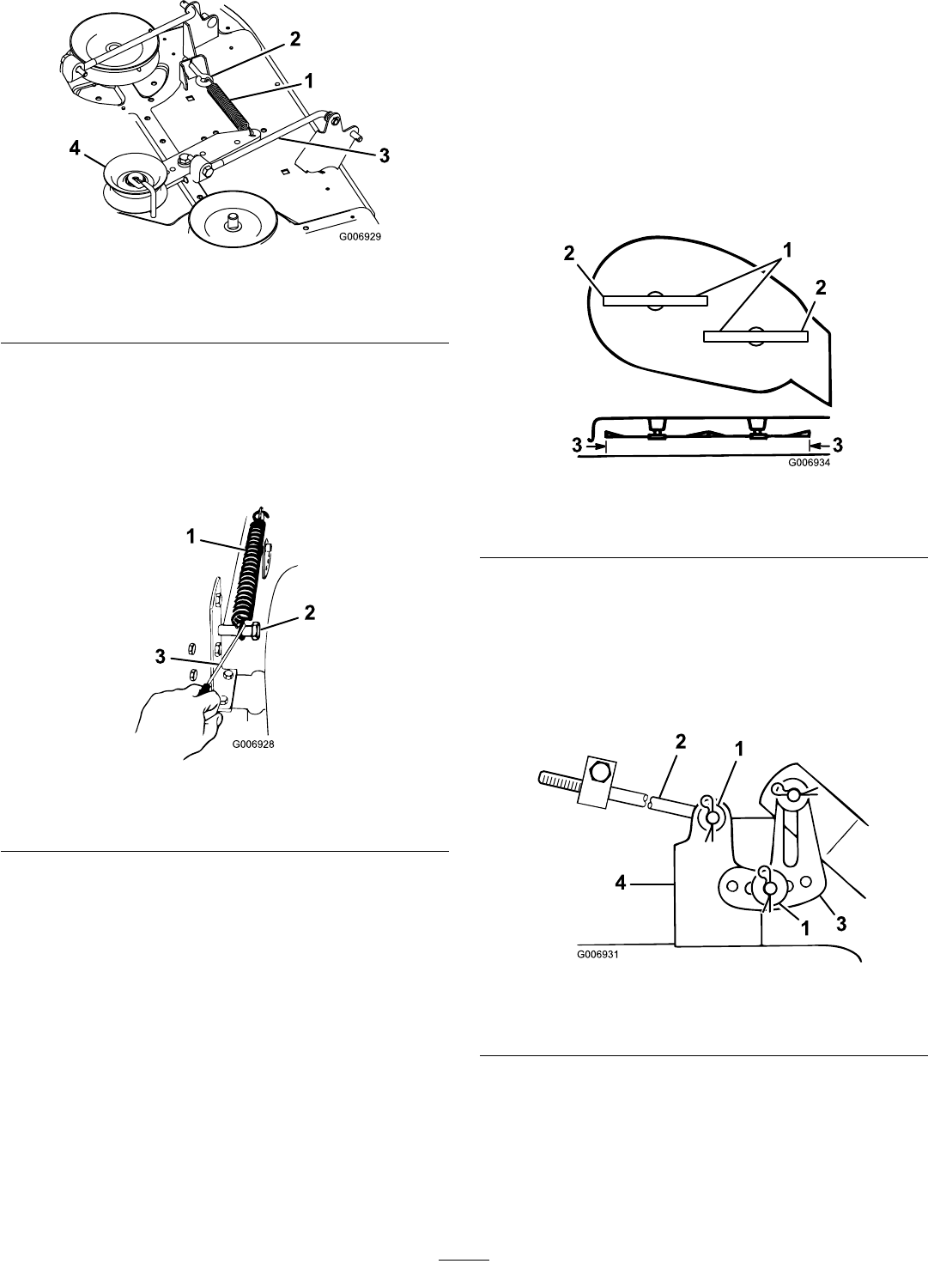
Figure57
1.Idlerspring3.Idlerarm
2.Eye-bolt4.Idlerpulley
17.Movetheheight-of-cutleverintotheDnotchto
makeiteasiertoinstalltheheight-of-cutliftassist
spring.
18.Hooktheliftassistspringbetweenthecutter
deckrightsideliftbracketandtheretainingbolt
(Figure58).
Figure58
1.Spring3.Springtool
2.Bolt
Note:Usethespringtoolprovidedwiththe
machine.
19.Checkthecutterdecklevel;refertoLevelingthe
CutterDeckfromSide-to-SideandFront-to-Rear
BladeSlope.
LevelingtheCutterDeckfrom
Side-to-Side
Thecutterdeckbladesmustbelevelfromsidetoside.
Checktheside-to-sidelevelwheneveryouinstallthe
cutterdeckorlookforanunevencutonyourlawn.
Beforeyoulevelthecutterdeck,settheairpressurein
thetyrestotherecommendedlevel;refertoChecking
theTyrePressure.
1.Parkthetractoronalevelsurface.
2.Disengagethebladecontrol(PTO)andsetthe
parkingbrake.
3.Stoptheengine,removethekey,andwaitforall
movingpartstostopbeforeleavingtheoperating
position.
4.Movetheheight-of-cutleverintotheCnotch.
5.Carefullyrotatethebladessidetoside(Figure59).
Figure59
1.Bladessidetoside3.Measurehere
2.Outsidecuttingedges
6.Measurebetweentheoutsidecuttingedgesandthe
atsurface(Figure59).Ifbothmeasurementsare
notwithin3/16inch(5mm),adjustthem;referto
7through10.
7.Removethehairpincotterandwasherfromthe
levelingbracket(Figure60).
Figure60
1.Hairpincotterandwasher3.Levelingbracket
2.Longrod4.CutterDeckmount
8.Positionthelevelingbracketinadifferentholeand
installthewasherandhairpincotter(Figure60).
Note:Positioningthelevelingbrackettowardthe
frontholelowersthebladeheight;positioningthe
levelingbrackettowardtherearholeraisestheblade
height.
39
9.Repeat7and8ontheoppositesideofthecutter
deck.
10.Checkthefront-to-rearbladeslope;referto
AdjustingtheFront-to-RearBladeSlope.
AdjustingtheFront-to-Rear
BladeSlope
Checkthefront-to-rearbladeslopewheneveryouinstall
thecutterdeck.Beforeyouchecktheslope,settheair
pressureinthetyrestotherecommendedlevel;referto
CheckingtheTyrePressure.Ifthefrontofthecutter
deckisnotwithinarangeof1/8to3/8inch(3to10
mm)lowerthantherearofthecutterdeck,adjustthe
bladeslopeasfollows:
1.Parkthetractoronalevelsurface.
2.Disengagethebladecontrol(PTO)andsetthe
parkingbrake.
3.Stoptheengine,removethekey,andwaitforall
movingpartstostopbeforeleavingtheoperating
position.
4.Checkandadjusttheside-to-sidebladelevelifyou
havenotcheckedthesetting;refertoLevelingthe
CutterDeckfromSide-to-Side.
5.Movetheheight-of-cutleverintothe“C”notch.
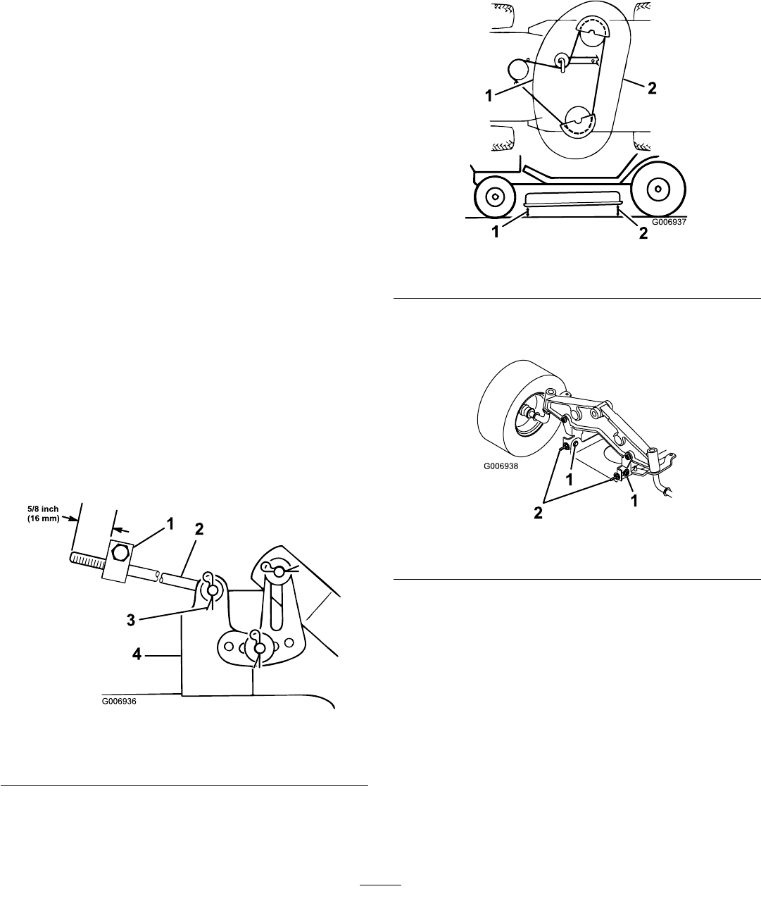
6.Measurethelengthoftherodextendingoutof
thefrontoftheadjustingblockonthesidesofthe
chassis(Figure61).Iftherodlengthisnot5/8inch
(16mm),removethehairpincotterandwasherfrom
theendoftherod(Figure61)andturntheroduntil
itextendsout5/8inch(16mm).
Figure61
1.Adjustingblock3.Hairpincotterandwasher
2.Longrod4.CutterDeckmount
7.Installtheendoftherodintotheholeinthecutter
deckmountandsecureitwiththewasherand
hairpincotter.
8.Repeat6and7ontheoppositesideofthecutter
deck.
9.Checkthefront-to-rearslopebymeasuringbetween
thebottomofthecutterdeck(frontcenterandrear
center)andtheatsurface(Figure62).Ifthefrontis
notwithinarangeof1/8to3/8inch(3to10mm)
lowerthantherear,anadjustit.
Figure62
1.Measurefrontcenter2.Measurerearcenter
10.Slightlyloosenthefrontpivotplatemountingbolts
(Figure63).
Figure63
1.Pivotmountingbolt2.Eyeboltlocknut
11.Rotatethelocknutsontheeyeboltstochangethe
adjustment(Figure63).
Note:Toraisethefrontofthecutterdeck,tighten
theeyeboltlocknuts;tolowerthefrontofthecutter
deck,loosentheeyeboltlocknuts.
12.Afteradjustingbothoftheeyeboltlocknutsevenly,
checkthefront-to-rearslopeagain.Continue
adjustingtheeyeboltsuntilthefrontbladetipis0to
3/8inch(0to9mm)lowerthantherearbladetip
(Figure63).
40
13.Whenthefront-to-rearslopeiscorrect,tightenthe
pivotplatemountingbolts(Figure63).
14.Whenthefront-to-rearbladeslopeiscorrect,check
theside-to-sidelevelofthecutterdeck;referto
LevelingtheCutterDeckfromSide-to-Side.
Cleaning
WashingtheUndersideofthe
CutterDeck
ServiceInterval:Beforeeachuseordaily
Washtheundersideofthecutterdecktoprevent
grassbuildupforimprovedmulchactionandclipping
dispersal.
1.Parkthetractoronalevelsurface.
2.Disengagethebladecontrol(PTO)andsetthe
parkingbrake.
3.Stoptheengine,removethekey,andwaitforall
movingpartstostopbeforeleavingtheoperating
position.
4.Attachthecoupling(notincluded)tothecutter
deckwashoutttingandturnthewateronhigh
(Figure64).
Figure64
1.Washouttting3.Hose
2.Coupling(notincluded)
Note:Spreadpetroleumjellyonthewashouttting
o-ringtomakethecouplingslideoneasierand
protecttheo-ring.
5.Lowerthecutterdecktothelowestheightofcut.
6.Sitontheseatandstarttheengine.
7.Engagethebladecontrol(PTO)andletthecutter
deckrunfor1to3minutes.
8.Disengagethebladecontrol(PTO).
9.Stoptheengine,removethekey,andwaitforall
movingpartstostopbeforeleavingtheoperating
position.
10.Removetheignitionkey.
11.Turnthewateroffandremovethecouplingfrom
thewashoutttingandhose.
12.Runthecutterdeckagainfor1to3minutesto
removetheexcesswater.
41

Abrokenormissingwashoutttingcould
exposeyouandotherstothrownobjectsorto
bladecontact.Contactwiththebladeorthrown
debriscontactmaycauseinjuryordeath.
•Replacebrokenormissingwashouttting
immediately,beforeusingthecutterdeck
again.
•Pluganyholesinthecutterdeckwithbolts
andlocknuts.
•Neverputyourhandsorfeetunderthecutter
deckorthroughopeningsinthecutterdeck.
Storage
1.Disengagethebladecontrol(PTO)andsetthe
parkingbrake.
2.Stoptheengine,removethekey,andwaitforall
movingpartstostopbeforeleavingtheoperating
position.
3.Removegrassclippings,dirt,andgrimefromthe
externalpartsoftheentiretractor,especiallythe
engine.Cleandirtandchafffromtheoutsideofthe
enginecylinderheadnsandblowerhousing.
Important:Youcanwashthetractorwitha
milddetergentandwater.Donotuseapressure
washertowashthetractor.Pressurewashing
maydamagetheelectricalsystemorwashaway
necessarygreaseatfrictionpoints.Avoidusing
waterexcessively,especiallynearthecontrol
panel,lights,engine,andbattery.
4.Checktheparkingbrake;refertoCheckingthe
ParkingBrake.
5.Servicetheaircleaner;refertoServicingtheAir
Cleaner.
6.Greasethechassis;refertoGreasingandLubricating
theTractor.
7.Changethecrankcaseoilandlter;refertoServicing
theEngineOil.
8.Checkthetyrepressure;refertoCheckingtheTyre
Pressure.
9.Whenstoringthetractorforover30days,prepareit
asfollows:
A.Addapetroleumbasedstabilizer/conditioner
tofuelinthetankaccordingtotheinstructions
fromstabilizermanufacture.Donotusean
alcoholbasedstabilizer(ethanolormethanol).
Note:Afuelstabilizer/conditionerismost
effectivewhenmixedwithfreshpetrolandused
atalltimes.
B.Runenginefor5minutestodistribute
conditionedfuelthroughthefuelsystem.
C.Stoptheengine,allowittocool,anddrainthe
fueltank;refertoDrainingtheFuelTank.
D.Starttheengineandrunituntilitstops.
E.Chokeorprimetheengine.
F.Startandruntheengineuntilitwillnotstart
again.
G.Recycletheoldfuelaccordingtolocalcodes.
Important:Donotstore
stabilizer/conditionedpetrolover90
days.
42

10.Removeandinspectthesparkplug;refertoServicing
theSparkPlug.Withthesparkplugremovedfrom
theengine,pour2tablespoonsofengineoilintothe
sparkplughole.Usetheelectricstartertocrank
theengineanddistributetheoilinsidethecylinder.
Installthesparkplug,butdonotconnectthewireto
thesparkplug.
11.Disconnectthenegativebatterycable.Cleanthe
batteryandbatteryterminals.Checktheelectrolyte
levelandchargeitfully;refertoServicingtheBattery.
Leavethenegativebatterycabledisconnectedfrom
thebatteryduringstorage.
Important:Thebatterymustbefullycharged
topreventitfromfreezingandbeingdamagedat
temperaturesbelow32°F(0°C).Afullycharged
batterycanbestoredduringthewinterwithout
recharging.
12.Checkandtightenallbolts,nuts,andscrews.Repair
orreplaceanypartthatiswornordamaged.
13.Paintallscratchedorbaremetalsurfaceswithpaint
availablefromanAuthorizedServiceDealer.
14.Storethetractorinaclean,drygarageorstoragearea.
Removetheignitionandreverseinterlockkeysfrom
thetractorandkeeptheminamemorableplace.
Coverthetractortoprotectitandkeepitclean.
43

Troubleshooting
ProblemPossibleCauseCorrectiveAction
1.Thebladecontrol(PTO)isengaged.1.Disengagethebladecontrol(PTO).
2.Theparkingbrakeisnoton.2.Settheparkingbrake.
3.Thebatteryisdead.3.Chargethebattery.
4.Theelectricalconnectionsarecorroded
orloose.
4.Checktheelectricalconnectionsfor
goodcontact.
5.Afuseisblown.5.Replacethefuse.
Thestarterdoesnotcrank.
6.Arelayorswitchisdamaged.6.ContactanAuthorizedServiceDealer.
1.Theoperatorisnotseated.1.Sitontheseat.
2.Thefueltankisempty.2.Fillthefueltankwithpetrol.
3.Theaircleanerisdirty.3.Cleanorreplacetheaircleaner
element.
4.Thesparkplugwireislooseor
disconnected.
4.Connectthewiretosparkplug.
5.Thesparkplugispitted,fouled,orthe
gapisincorrect.
5.Installanew,correctlygappedspark
plug.
6.Thechokeisnotclosing.6.Adjustthethrottlecable.
7.Thereisdirtinthefuellter.7.Replacethefuellter.
8.Theidlespeedistooloworthemixture
isincorrect.
8.Adjustthecarburettoridlespeedand
idlemixture.
Theenginewillnotstart,startshard,or
failstokeeprunning.
9.Dirt,water,orstalefuelisinthefuel
system.
9.ContactanAuthorizedServiceDealer.
1.Theengineloadisexcessive.1.Reducethegroundspeed.
2.Theaircleanerisdirty.2.Cleantheaircleanerelement.
3.Theoillevelinthecrankcaseislow.3.Addoiltothecrankcase.
4.Thecoolingnsandairpassages
undertheengineblowerhousingare
plugged.
4.Removetheobstructionfromthe
coolingnsandairpassages.
5.Thesparkplugispitted,fouled,orthe
gapisincorrect.
5.Installanew,correctlygappedspark
plug.
6.Theventholeinthefuelcapisplugged.6.Cleanorreplacethefuelcap.
7.Thereisdirtinfuellter.7.Replacethefuellter.
Theenginelosespower.
8.Dirt,water,orstalefuelisinthefuel
system.
8.ContactanAuthorizedServiceDealer.
1.Theengineloadisexcessive.1.Reducethegroundspeed.
2.Theoillevelinthecrankcaseislow.2.Addoiltothecrankcase.
Theengineoverheats.
3.Thecoolingnsandairpassages
undertheengineblowerhousingare
plugged.
3.Removetheobstructionfromthe
coolingnsandairpassages.
1.Thebladesarebentorunbalanced.1.Installnewblades.
2.Theblademountingboltisloose.2.Tightentheblademountingbolt.
3.Theenginemountingboltsareloose.3.Tightentheenginemountingbolts.
4.Thereisalooseenginepulley,idler
pulley,orbladepulley.
4.Tightentheappropriatepulley.
Thereisanabnormalvibration.
5.Theenginepulleyisdamaged.5.ContactanAuthorizedServiceDealer.
1.Thebladedrivebeltisworn,loose,or
broken.
1.Installanewbladedrivebelt. Thebladesdonotrotate.
2.Thebladedrivebeltisoffofthepulley.2.Installthebladedrivebeltandcheck
theidlerpulleyandbeltguidesforthe
correctposition.
44

ProblemPossibleCauseCorrectiveAction
1.ThedrivecontrolisinthePushposition.1.MovethedrivecontroltotheOperate
position.
2.Thetractionbeltisworn,loose,or
broken.
2.ContactanAuthorizedServiceDealer.
Thetractordoesnotdrive.
3.Thetractionbeltisoffofthepulley.3.ContactanAuthorizedServiceDealer.
1.Thetyrepressureisincorrect.1.Setthetyrepressure.
2.Thecutterdeckisnotlevel.2.Levelthecutterdeckfromside-to-side
andfront-to-rear.
Thecutterdeckiscuttingunevenly.
3.Theundersideofthecutterdeckis
dirty.
3.Cleantheundersideofthecutterdeck.
45
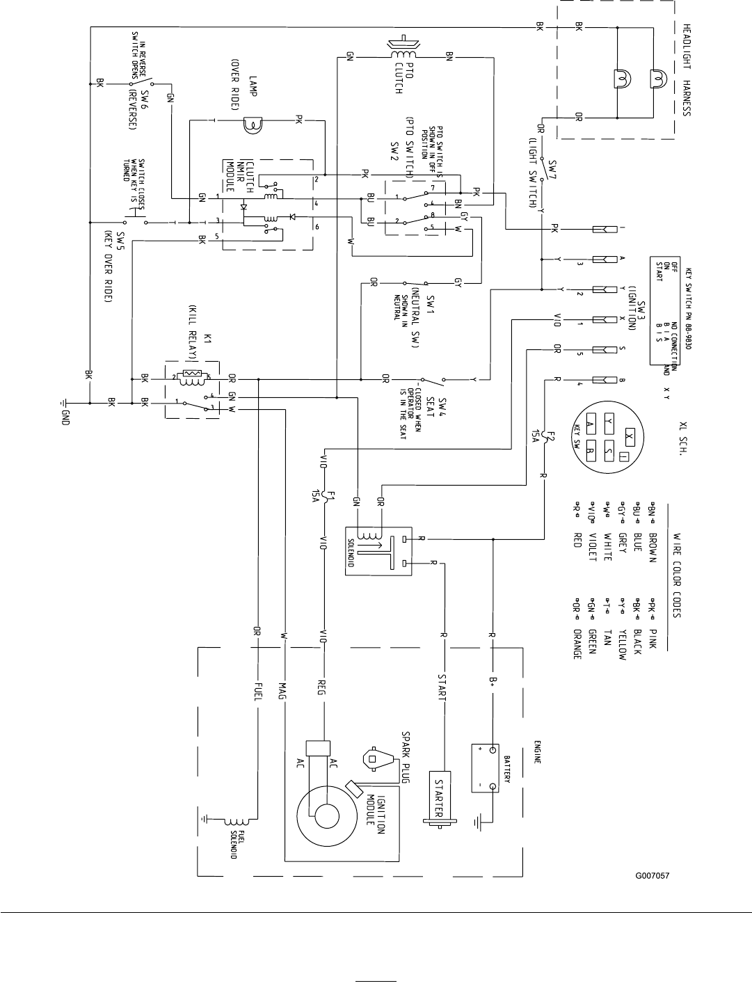
Schematics
WiringDiagram(Rev.A)
46

Notes:
47

Notes:
48

1st Year (12 months)
We certify that this service has been
carried out by an Authorised Hayter
Service Dealer
Date:
1st Year (12 months)
Owner’s Name:
Serial Number:
Date:
2nd Year (24 months)
We certify that this service has been
carried out by an Authorised Hayter
Service Dealer
Date:
Owner’s Name:
Serial Number:
Date:
Note for dealer: Please retain this voucher for your records.
Note for dealer: Please retain this voucher for your records.
2nd Year (24 months)

LIMITED WARRANTY
Hayter Limited warrants to the original user/purchaser that this unit shall be free from defects
in material and workmanship under normal use and service for a period of three years from the
date of purchase. The manufacturer of major proprietry components ie. engines, gearbox /
transaxle (where applicable) furnish their own warranty and services are provided through their
authorised network. To qualify for the full benefit of the warranty, the warranty registration card
must be returned within 14 days of purchase. Subject to the conditions and exclusions noted in
this limited warranty, we shall at our option, repair or replace any warranted part during the
applicable period. If you are in doubt or experience any difficulty, please consult a Hayter
Authorised Service Dealer for clarification.
To qualify for the extended warranty (second and third year) of the three year limited warranty
the machine must have annual services carried out by an Authorised Hayter Service Dealer.
These chargeable services should be carried out within 12 and 24 months of the date of purchase.
Excluded from the extended warranty period are those items which are subject to normal wear
and tear e.g. tyres, wheels, cutterblades, belts, cables, grassbags, brush/bristles, batteries and
other consumable wearing parts.
All consumer machines which are fitted with a genuine Hayter friction disc as original
equipment before use, are covered by a Lifetime Warranty against the engine crankshaft
bending. Note: friction washers, blade brake clutch (B.B.C) units and other such devices are not
applicable. Only machines fitted with a genuine Hayter friction disc, which are used in
accordance with the recommended operating and maintenance procedures, are covered.
This warranty does not apply to any unit that has been tampered with, altered, misused, abused or
used for hire, and will become invalid if non genuine Hayter parts are fitted. This warranty does
not cover minor mechanical adjustments unless they are due to defective material or
workmanship. Consult the Owner's Handbook or a Hayter Authorised Service Dealer for
assistance when making these adjustments.
A warranty period of 90 days applies to machines used for commercial purposes.
To make a warranty claim, return the unit to a Hayter authorised dealer along with proof of
purchase stating the machine serial number and date of purchase. The service receipt(s) or this
Owners Handbook with the 1st/2nd year service boxes fully completed, must be produced as
proof of entitlement to the extended warranty period. Subject to the conditions and exclusions in
this limited warranty, the authorised dealer will, at our option, repair or replace any warranted
part within the duration of the warranty period.
This limited warranty gives you specific legal rights and is in addition to any statutory rights to
which you may be entitled and your statutory rights are not affected by this warranty. If you need
additional information concerning this written warranty, or assistance in obtaining services,
please write to : HAYTER LIMITED, Service Department, Spellbrook, Bishop's Stortford,
Hertfordshire CM23 4BU
UK ONLY: Details of your local Hayter authorised dealer are contained in Yellow Pages and
the Hayter website www.hayter.co.uk or contact:- Freephone 0800 616298.
Issue: 12.08.03

CUS
TOMER
INFO
RMATION
Date of Sale:-
Your Local Dealer:-
HAYTER LIMITED, SPELLBROOK, BISHOP’S STORTFORD, HERTS. CM23 4BU, ENGLAND
Code Serial No.
